EP3335946A1 - Organ für ein anschlusssystem eines wischerblatts an einen scheibenwischerarm - Google Patents
Organ für ein anschlusssystem eines wischerblatts an einen scheibenwischerarm Download PDFInfo
- Publication number
- EP3335946A1 EP3335946A1 EP17204054.5A EP17204054A EP3335946A1 EP 3335946 A1 EP3335946 A1 EP 3335946A1 EP 17204054 A EP17204054 A EP 17204054A EP 3335946 A1 EP3335946 A1 EP 3335946A1
- Authority
- EP
- European Patent Office
- Prior art keywords
- axis
- blade
- rotation
- wiper
- ellipsoidal
- Prior art date
- Legal status (The legal status is an assumption and is not a legal conclusion. Google has not performed a legal analysis and makes no representation as to the accuracy of the status listed.)
- Withdrawn
Links
- 230000000295 complement effect Effects 0.000 claims abstract description 14
- 210000000056 organ Anatomy 0.000 claims description 9
- 210000004417 patella Anatomy 0.000 claims 1
- 244000007853 Sarothamnus scoparius Species 0.000 description 8
- 239000000463 material Substances 0.000 description 7
- 238000012550 audit Methods 0.000 description 4
- 238000006073 displacement reaction Methods 0.000 description 4
- 238000007373 indentation Methods 0.000 description 3
- 210000000078 claw Anatomy 0.000 description 2
- 230000005489 elastic deformation Effects 0.000 description 2
- 230000003071 parasitic effect Effects 0.000 description 2
- XLYOFNOQVPJJNP-UHFFFAOYSA-N water Substances O XLYOFNOQVPJJNP-UHFFFAOYSA-N 0.000 description 2
- 238000005452 bending Methods 0.000 description 1
- 230000000903 blocking effect Effects 0.000 description 1
- 238000002788 crimping Methods 0.000 description 1
- 239000013013 elastic material Substances 0.000 description 1
- 238000005516 engineering process Methods 0.000 description 1
- 238000002347 injection Methods 0.000 description 1
- 239000007924 injection Substances 0.000 description 1
- 239000007788 liquid Substances 0.000 description 1
- 238000000465 moulding Methods 0.000 description 1
- 230000002093 peripheral effect Effects 0.000 description 1
- 238000007747 plating Methods 0.000 description 1
- 239000000243 solution Substances 0.000 description 1
- 238000005406 washing Methods 0.000 description 1
Images


Classifications
-
- B—PERFORMING OPERATIONS; TRANSPORTING
- B60—VEHICLES IN GENERAL
- B60S—SERVICING, CLEANING, REPAIRING, SUPPORTING, LIFTING, OR MANOEUVRING OF VEHICLES, NOT OTHERWISE PROVIDED FOR
- B60S1/00—Cleaning of vehicles
- B60S1/02—Cleaning windscreens, windows or optical devices
- B60S1/04—Wipers or the like, e.g. scrapers
- B60S1/32—Wipers or the like, e.g. scrapers characterised by constructional features of wiper blade arms or blades
- B60S1/38—Wiper blades
- B60S1/3848—Flat-type wiper blade, i.e. without harness
- B60S1/3849—Connectors therefor; Connection to wiper arm; Attached to blade
-
- B—PERFORMING OPERATIONS; TRANSPORTING
- B60—VEHICLES IN GENERAL
- B60S—SERVICING, CLEANING, REPAIRING, SUPPORTING, LIFTING, OR MANOEUVRING OF VEHICLES, NOT OTHERWISE PROVIDED FOR
- B60S1/00—Cleaning of vehicles
- B60S1/02—Cleaning windscreens, windows or optical devices
- B60S1/04—Wipers or the like, e.g. scrapers
- B60S1/32—Wipers or the like, e.g. scrapers characterised by constructional features of wiper blade arms or blades
- B60S1/40—Connections between blades and arms
-
- B—PERFORMING OPERATIONS; TRANSPORTING
- B60—VEHICLES IN GENERAL
- B60S—SERVICING, CLEANING, REPAIRING, SUPPORTING, LIFTING, OR MANOEUVRING OF VEHICLES, NOT OTHERWISE PROVIDED FOR
- B60S1/00—Cleaning of vehicles
- B60S1/02—Cleaning windscreens, windows or optical devices
- B60S1/04—Wipers or the like, e.g. scrapers
- B60S1/32—Wipers or the like, e.g. scrapers characterised by constructional features of wiper blade arms or blades
- B60S1/34—Wiper arms; Mountings therefor
- B60S1/3425—Constructional aspects of the arm
- B60S1/3445—Joints between elements
- B60S1/345—Joints between elements the elements being a link piece and a mounting head
- B60S1/3452—Joints between elements the elements being a link piece and a mounting head the joint being a snap fit pivot joint
-
- B—PERFORMING OPERATIONS; TRANSPORTING
- B60—VEHICLES IN GENERAL
- B60S—SERVICING, CLEANING, REPAIRING, SUPPORTING, LIFTING, OR MANOEUVRING OF VEHICLES, NOT OTHERWISE PROVIDED FOR
- B60S1/00—Cleaning of vehicles
- B60S1/02—Cleaning windscreens, windows or optical devices
- B60S1/04—Wipers or the like, e.g. scrapers
- B60S1/32—Wipers or the like, e.g. scrapers characterised by constructional features of wiper blade arms or blades
- B60S1/38—Wiper blades
- B60S1/3848—Flat-type wiper blade, i.e. without harness
- B60S1/3849—Connectors therefor; Connection to wiper arm; Attached to blade
- B60S1/3865—Connectors having an integral pivot pin for connection with the wiper arm
- B60S1/3868—Connectors having an integral pivot pin for connection with the wiper arm pin formed on the exterior of side walls
Definitions
- the present invention relates to a member for a connection system of a broom to a wiper arm.
- a car is conventionally equipped with windshield wipers to wash the windshield and to prevent the driver's vision from being disturbed.
- These wipers generally comprise a drive arm, performing an angular reciprocating movement, and elongated brushes, themselves carrying wiper blades, otherwise called scraper blades and made of an elastic material. These blades rub against the windshield and evacuate the water by bringing it out of the driver's field of vision.
- the brooms are made in the form, or, in a conventional version, articulated stirrups that hold the scraper blade in several discrete places by giving it a bend allowing it to marry the eventual curvature of the windshield, or, in a newer version called " flat blade " (for "flat blade”), a semi-rigid assembly that keeps the scraper blade along its length thanks to one or bending vertebrae to apply the broom on the bumper -brise without having to use stirrups.
- the blade is generally attached to the drive arm by a connector system including a connector and an adapter.
- the connector is a part usually fixed permanently on the aforementioned semi-rigid assembly of the broom.
- the adapter is an intermediate adapter that allows the connection and attachment of the connector to the drive arm. It is generally configured to be engaged in a head or end piece in the form of a fork of the drive arm.
- Each of these members comprises rotation means configured to cooperate with complementary means of the other member, to define at least one axis of rotation of the members, which is also an axis of rotation of the blade vis-à-vis -vis of the arm.
- one of the members such as the connector, comprises a substantially cylindrical, substantially cylindrical pivoting axis which defines the axis of rotation and which is received in a housing of complementary shape to the other member.
- a windscreen wiper blade comprising articulated stirrups comprising spherical articulation means able to fit into housings made in complementary stirrups, so as to obtain an articulation without play between said stirrups.
- the invention proposes an alternative to these technologies that is simple, effective and economical, and allows as far as necessary greater freedom of movement in terms of articulation with respect to these prior arts.
- the invention proposes for this purpose a member for a connection system of a blade to a wiper arm, said member, said first member, being configured to be secured to said blade or said arm and comprising means for articulation configured to cooperate with complementary articulation means of another member of the connection system, said second member, for defining at least one means for fixing and pivoting about a Y axis of rotation of said first member vis-à-vis said second member, said articulation means of said first member comprising a ball joint of at least partially spherical, ellipsoidal or ovoid shape, said first member being characterized in that it comprises only one and single ball joint at least partially spherical, ellipsoidal or ovoid shape.
- the presence of a single ball allows, when desired, to introduce and adjust longitudinal and / or lateral clearances between said first member and said second member, in order to increase the angle d attacking the wiper blade at the reversal positions thereof (said “fixed stop” and “opposite fixed stop” positions, also known as “inwipe” and “outwipe” positions). This avoids for example having to resort to a twisted drive head at a wiper motor output shaft or at an output shaft of a windshield wiper linkage.
- the present invention also relates to a system for connecting a blade to a wiper arm, said system comprising a first member according to any one of the preceding definitions and a second member according to any one of the preceding definitions.
- connection system allows three degrees of freedom (ie three possibilities of rotation) of the second member on said first member.
- connection system allows two degrees of freedom (or two possibilities of rotation) of the second member on said first member.
- connection system allows only one degree of freedom (ie a single possibility of rotation) of the second member on said first member.
- said first member is a connector configured to be secured to said blade, in particular to one or more stiffening vertebrae of the blade.
- the means of rotation of the first member are mounted in complementary means of the second member by resilient latching.
- the present invention further relates to a wiper blade, characterized in that it comprises or carries a first member or a system according to any one of the preceding definitions.
- the longitudinal or lateral designations refer to the orientation of the wiper blade or the drive arm, otherwise known as the wiper arm.
- the longitudinal direction corresponds to the main axis of the wiper blade or the wiper arm in which it extends
- the lateral orientations correspond to concurrent lines, that is to say which cross the longitudinal direction, in particular perpendicular to the longitudinal axis of the wiper blade or the wiper arm in its plane of rotation.
- the names outside (or front) or inside (or back) are appreciated relative to the attachment point of the wiper blade on the wiper arm, the inner denomination corresponding to the part where the Wiper arm and half broom extend.
- the directions referenced as upper or lower correspond to orientations perpendicular to the plane of rotation of the windscreen wiper blade on the windshield, the lower denomination containing the plane of the windshield.
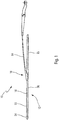
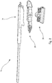
- FIG 1 shows a wiper 10 as a whole, this wiper 10 having a wiper blade 12, a wiper arm 14 (partially shown) for driving the wiper blade 12, and a wiper system 12 connecting the wiper blade 12 to the wiper arm 14.
- the wiper arm 14 shown here is a "Pinch Tab" type arm well known to those skilled in the art and better described in the document EP1565359 A1 .
- Other types of arms can naturally be used in the context of the present invention.
- the wiper arm 14 is intended to be driven by a motor to follow a reciprocating angular movement to evacuate the water and possibly other undesirable elements covering the windshield.
- the wiper blade 12 is preferably of the flat broom type. It comprises for example a longitudinal body 18, a wiper blade 20 made of material of the longitudinal body 18 or attached thereto, for example rubber, and at least one vertebra 15 which stiffens the blade 20 and promotes its application on the windshield.
- the body 18 of the wiper blade 12 may advantageously comprise a top aerodynamic deflector 22 intended to improve the operation of the windscreen wiper, the purpose of this deflector 22 being to improve the plating of the blade on the windshield and therefore the aerodynamic performance of the windshield wiper.
- the wiper blade 12 may further comprise end-pieces 24 for attaching the blade 20 and / or the vertebra 15 to the body 18, these end-pieces 24 being situated at each of the longitudinal ends of the body 18.
- the body 18 of the blade can also be made in two parts which are arranged substantially end to end and connected to one another by an intermediate member 26, here a connector, which is part of the connection system 16. These parts can be independent of each other or linked together by a median part of the body 18, defined by a partial cutout of the body 18. In this case, the blade 20 is generally attached to the longitudinal body 18.
- the member 26 is generally attached to the blade between the two parts of the body 18 and may include means for connection to these parts.
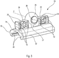
- the connector 26 may also comprise fixing means on the or the stiffening vertebrae 15 of the blade. It can thus comprise lower claws 28 defining longitudinal grooves for receiving, generally by sliding, lateral end portions of the lateral or vertebrae 15, as can be seen in FIG. figure 3 .
- the member 26 is preferably configured to be permanently attached to the wiper blade 12.
- connection system 16 further comprises a second member 30, here an adapter, which is configured to be secured to the wiper arm 14 and which is mounted on the first member 26 so as to maintain at least one degree of freedom pivoting about an axis of rotation Y which is a transverse axis substantially perpendicular to the longitudinal axis of the wiper blade 12.
- This degree of freedom allows a pivoting of the wiper blade 12 vis-à-vis the arm wiper 14 and thus allows the broom 12 to follow the curvature of the windshield during its movements.
- the means of rotation of the first member 26 comprise a single and single ball joint and not a physical axis of cylindrical shape, or a plurality of ball joints as in the prior art.
- the first member or connector 26 of the Figures 1 to 5 has a generally elongate shape in the longitudinal direction of the wiper blade 12. It comprises two lower side walls 32 interconnected at their respective upper end by a transverse wall 34 substantially perpendicular to the lateral ends of the walls 32.
- the walls 32, 34 here have an elongated shape in the longitudinal direction.
- the walls 32 carry or include the aforementioned claws 28.
- the first member 26 comprises a spherical connection of at least partially spherical, ellipsoidal or ovoidal shape, which is here formed by a spherical body 35, this body 35 being intended to be engaged, preferably by elastic latching, in a recess 60 (visible in figure 10 ) of complementary shape of the adapter 30.
- the spherical body 35 is here made of material of the wall 34, and is located substantially in the middle of the upper part of the connector 26.
- the body 35 here defines a sphere portion of center A.
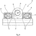
- the body 35 has in section an angular extent ⁇ of 180 ° around the center A, delimited in part by the upper faces of the locking and guiding means 38 described below. after.
- This angular extent that can be measured in a median transverse plane including the Y axis (as shown in FIG. figure 8 which illustrates an embodiment variant of the first member according to the invention), or else measured in a median longitudinal plane perpendicular to the Y axis, as illustrated in FIGS. Figures 4-6 .
- the body 35 here comprises a through hole 36 which extends along the Y axis.
- This orifice 36 has a substantially cylindrical shape and is configured to receive a cylindrical rod of an arm when the latter is of the lateral locking type. , for example of the "Side-Lock" type well known to those skilled in the art, and better described in the application US6553607 BA .
- the blocking and guiding means 38 comprise at least one, and preferably two, blocks made of material of the upper wall 34. These blocks, which are substantially parallelepipedic, extend upwards at the front and at the rear of the body 35, and each comprise two faces lateral surfaces 39.
- the lateral faces 39 comprise protuberances 42 intended to cooperate by sliding with corresponding means 54 of the second member 30 (visible on the figure 10 ) to firstly allow and guide the pivoting of the first member 26 vis-à-vis the second member about the Y axis, and secondly, cooperate by bearing or abutment with the corresponding means 54 of the second member 30 to limit or even prevent parasitic displacements of the first member 26 vis-à-vis the second member around the center A, such as displacements around the longitudinal axis of the brush for example.
- the means 38 and the body 35 are here aligned longitudinally, one behind the other in the median longitudinal plane.
- the assembly of the wiper blade 12 on the wiper arm 14 can be achieved simply by having the connector 26 secured to the blade 12 directly under the adapter 30 secured to the arm 14, and then by displacing in translation the connector towards the adapter in a direction substantially perpendicular to the longitudinal axis of the blade, until the body 35 engages elastically snap-fastening in the complementary means 60 of the adapter 30 (visible on the figure 10 ) and that the means 38 engage in the housing 45 of the adapter 30.
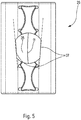
- the figure 5 is a schematic top view of the first member 26 of the first embodiment of the invention.
- the orifice 36 is preferably delimited on each lateral face of the body 35 by a peripheral edge comprising a flat part 37.
- Each flat part 37 is arranged so that the width of the spherical body 35 increases from the front to the right. rearward of the first member 26, at the orifice 36.
- the first member 26 can easily be assembled with the second member 30 by a linear translational movement of the spherical body 35 inside the second member 30, until elastic snap-fastening of the body 35 in complementary means 60 (visible in figure 10 ) of the second member 30.
- the reduced width of the front side of the spherical body 35 (visible in figure 5 ) is therefore intended to facilitate the introduction of the latter in the second member 30.
- the present invention is however not limited to such an embodiment and it is alternatively possible to have a first member 26 which is symmetrical with respect to a median vertical plane perpendicular to the longitudinal axis of the first member 26, that is to say symmetrical with respect to a plane comprising the axis of rotation Y.
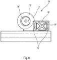
- the figure 6 represents another variant embodiment of the first member 26.
- the member 26 ' differs from the Figures 2 to 5 in that the locking and guiding means 38 'comprise only a single block in the rear part of the member 26', this block being here substantially parallelepipedic. Due to the absence of a block at the front of the member 26 ', the body 35' can here have an angular extent ⁇ 'around the center A which is significantly greater than that of the member 26 of the Figures 1 to 5 for example here about 250 °.
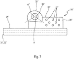
- the figures 7 and 8 represent yet another alternative embodiment of the first member 26.
- the member 26 “comprises an ovoid-shaped body 35" and the locking and guiding means 38 “comprise a single block 38" at the rear of the body 35 "This block 38" comprises on its lateral faces protuberances 42 "shaped pads or half-disks configured to bear against the inner walls of the second member 30, to limit or prevent parasitic movement of the connector 26" vis-à-vis the adapter 30 around the center A, such as displacements around the longitudinal axis of the broom for example.
- the surface of the protuberances 42 "in contact with the second member 30 is small enough not to create too great frictional forces between the block 38" and the member 30, which would hinder the rotation of the second member 30 screws
- the present invention is not limited to such an embodiment and alternatively it is possible to have one or more blocks whose side faces 39 "are free of protuberances 42", and are for example flat.
- the locking and guiding means 38 "carry the body 35" which is directly connected to one of their longitudinal ends.
- the assembly of the wiper blade 12 on the wiper arm 14 can be performed simply as described above.
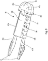
- the figure 9 represents the second organ used in the invention.
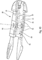
- the second member 30 is an elongated adapter along the longitudinal axis of the blade. It comprises a body having two side walls 43a, 43b substantially parallel to each other and to the axis A, and at a distance from one another. These walls 43a, 43b are interconnected at their upper ends by an upper transverse wall 44 substantially perpendicular to the walls 43a, 43b. This upper transverse wall 44 may also be called the base of the second member or adapter 30.
- the lateral and transverse walls 43a, 43b and 44 here have an elongate shape in the longitudinal direction.
- the lateral and transverse walls 43a, 43b, 44 of the adapter 30 define between them a longitudinal space or housing 45 in which is intended to be mounted the spherical body, ellipsoidal or ovoidal 35 of the first member 26.
- the walls 43a, 43b are here of the double-skin type and each comprise two skins, respectively internal 47 and external 48 (visible in figure 10 ), parallel and at a distance transverse to each other.
- the skins are connected together by transverse rectilinear ribs 50, as visible in FIG. figure 10 .
- the body of the adapter 30 is connected at one of its longitudinal ends to a fairing or cowling, also called cap or head 46.
- This head 46 has a lateral dimension greater than that of the body of the adapter and a height also greater to that of the body.
- the lateral walls 43a, 43b of the body of the adapter 30 are thus set back or offset relative to external lateral faces 46a, 46b of the head, and its upper wall 44 is recessed or offset with respect to an external upper face. 46c of the head.
- the upper wall 44 of the body of the adapter 30 further comprises an upper orifice 51 for engaging a tongue of the arm "Pinch Tab" mentioned above.
- This upper orifice 51 is here formed partly in the head 46, at the rear end thereof, and partly in the upper wall 44, at the front end thereof.
- the orifice 51 has a general shape, for example square or rectangular, formed for example by two U-shaped indentations, a first U-shaped indentation being on the cap 46 and facing a second U-shaped indentation located on the upper wall 44.
- the side walls 43a, 43b of the body extend towards the rear of the adapter 30, by tabs 52a, 52b that are elastically deformable and extend longitudinally.
- Each side wall 43a, 43b is connected to a tab 52a, 52b, these tabs 52a, 52b being parallel or inclined with respect to each other, and symmetrical with respect to a median longitudinal plane, substantially vertical, it is that is perpendicular to the upper wall 44 of the adapter.
- Each tab 52a, 52b thus carries a push button 27.
- the elastic deformations of the tabs 52a, 52b here take place in a substantially horizontal longitudinal plane, that is to say substantially parallel to the upper wall 44.
- the tabs 52a, 52b can be brought closer to one another by elastic deformation.
- the push buttons 27 are shaped to cooperate with notches of the "Pinch Tab” arm, as described in the document EP1565359 A1 .
- the side walls 43a, 43b each comprise a through orifice 56.
- the openings 56 of the walls 43a, 43b are substantially coaxial and here define the axis Y of pivoting of the adapter 30 on the connector 26, and therefore of the wiper blade 12 vis-à-vis the wiper arm 14.
- the orifices 56 are here circular section.
- the orifices 56 open at their outer lateral ends on the outer faces of the walls 43a, 43b, respectively, and at their inner lateral ends in the housing 45.
- the internal lateral faces facing the lateral walls 43a, 43b comprise cavities 60.
- Each side wall 43a, 43b comprises a cavity 60, the cavities 60 being here facing one another and each extending in a inward direction of the side walls 43a, 43b, that is to say in the direction of the space separating the two inner skins 47 and outer 48 mentioned above.
- the cavities 60 are symmetrical with respect to a median longitudinal plane of the adapter, perpendicular to the upper wall 44.
- Each cavity 60 also has a plane of symmetry passing through the Y axis.
- the cavities 60 of the second member 30 have a shape complementary to the ball of partially spherical shape of the first member 26 of the Figures 2-6 .
- these cavities 60 will be respectively of concave shape at least partially ellipsoidal or ovoid complementary to the shape of the body 35, if it is ellipsoidal or ovoid.
- Each cavity 60 is here perforated and comprises in particular a through hole. This hole is here formed by one of the aforementioned orifices 56. Each cavity 60 is thus located on the inner skin 47 of the side wall 43a or 43b so as to be traversed by the orifice 56 of this wall.
- each orifice 56 which coincides with the axis Y, is also coincident with the axis of the corresponding cavity 60, so that the orifices are centered relative to the body 35.
- Each cavity 60 has an outer diameter which is about 60 to 80% of the height of the corresponding side wall 43a, 43b, measured in a substantially vertical direction perpendicular to the top wall 44.
- the side walls 43a, 43b of the body of the adapter 30 further comprise on their inner lateral faces means 54 protruding which define bearing faces in the transverse direction. At least some of these projecting means 54 are configured to be in contact with the protuberances 42 mentioned above or alternatively with the side faces 39, which may in particular be planar.
- the projecting means here comprise strips of material 54 projecting from the inner lateral faces of the side walls 43a, 43b.
- the strips of material have an elongated shape and extend longitudinally between the lower and upper longitudinal edges of the walls 43a, 43b.
- the strips of material 54 define substantially parallel bearing faces. These bearing faces are here substantially parallel to the external lateral faces of the walls 43a, 43b and to the longitudinal axis of the adapter 30.
- the adapter 30 described above is advantageously unitary, that is to say constituted by the same synthetic plastic material. It can thus be manufactured during a single molding operation, in particular by injection.
- the adapter 30 is fixed to the connector 26 by virtue of the body 35 and the cavities 60 which form means for fixing the adapter 30 to the connector 26, and for pivoting the adapter 30 with respect to the connector 26.
- the fastening means are of the elastic snap type, the cavities 60 of the adapter 30 being intended to cooperate by elastic snap-fastening with the body 35.
- the upper wall 44 of the second member or adapter 30 comprises a cavity 62 in which an upper portion of the spherical body 35 may be received. This receiving cavity makes it possible to reduce the height of the assembly formed by the first 26 and second 30 members. when they are assembled with each other.
- the connector 26 is arranged to be secured, for example by crimping, the wiper blade 12.
- the connector 26 can also provide a transport function and distribution of a washing liquid from the windshield of the vehicle.
Landscapes
- Engineering & Computer Science (AREA)
- Mechanical Engineering (AREA)
- Pivots And Pivotal Connections (AREA)
- Brushes (AREA)
- Toys (AREA)
Applications Claiming Priority (1)
| Application Number | Priority Date | Filing Date | Title |
|---|---|---|---|
| FR1662558A FR3060496B1 (fr) | 2016-12-15 | 2016-12-15 | Organe pour un systeme de connexion d'un balai a un bras d'essuie-glace |
Publications (1)
| Publication Number | Publication Date |
|---|---|
| EP3335946A1 true EP3335946A1 (de) | 2018-06-20 |
Family
ID=57796727
Family Applications (1)
| Application Number | Title | Priority Date | Filing Date |
|---|---|---|---|
| EP17204054.5A Withdrawn EP3335946A1 (de) | 2016-12-15 | 2017-11-28 | Organ für ein anschlusssystem eines wischerblatts an einen scheibenwischerarm |
Country Status (3)
| Country | Link |
|---|---|
| US (1) | US20180170317A1 (de) |
| EP (1) | EP3335946A1 (de) |
| FR (1) | FR3060496B1 (de) |
Citations (7)
| Publication number | Priority date | Publication date | Assignee | Title |
|---|---|---|---|---|
| FR2247897A7 (en) * | 1973-10-11 | 1975-05-09 | Bosch Gmbh Robert | Automobile wiper assembly - with operating arm connected to blade by a ball joint |
| FR2453757A1 (fr) | 1979-04-12 | 1980-11-07 | Ducellier & Cie | Balai d'essuie-glace |
| US6553607B1 (en) | 1999-05-28 | 2003-04-29 | Robert Bosch Gmbh | Wiper device for motor vehicle windows |
| EP1565359A1 (de) | 2002-11-26 | 2005-08-24 | Valeo Wischersysteme GmbH | Vorrichtung zum lösbaren verbinden eines wischblatts mit einem antreibbaren wischarm |
| DE102011012245A1 (de) * | 2011-02-24 | 2012-08-30 | Daimler Ag | Anbindungselement zum Anbringen eines Wischblatts an einem Wischarm und Wischarmanordnung |
| WO2014020283A1 (fr) * | 2012-08-02 | 2014-02-06 | Valeo Systemes D'essuyage | Systeme de connexion entre un bras d'essuyage et un balai d'essuyage |
| WO2017119853A1 (en) * | 2016-01-06 | 2017-07-13 | Teklas Kaucuk Sanayi Ticaret A. S. | A connecting device for the vehicle wipers |
Family Cites Families (14)
| Publication number | Priority date | Publication date | Assignee | Title |
|---|---|---|---|---|
| US969187A (en) * | 1909-06-21 | 1910-09-06 | Micajah L Poulter | Crumber. |
| US1658389A (en) * | 1921-07-26 | 1928-02-07 | Trico Products Corp | Cleaner for windshields and the like |
| US2012313A (en) * | 1932-10-29 | 1935-08-27 | Lark Raymond Percival | Windscreen wiper for road vehicles |
| US2338496A (en) * | 1937-11-15 | 1944-01-04 | Ohio Crankshaft Co | Heat treating gears and the like |
| US2247897A (en) * | 1940-03-22 | 1941-07-01 | Spraying Systems Co | Spray nozzle |
| US2348502A (en) * | 1941-07-11 | 1944-05-09 | Productive Inventions Inc | Windshield wiper |
| US2648865A (en) * | 1946-05-15 | 1953-08-18 | Harry B Gordon | Windshield wiper |
| US2915769A (en) * | 1957-07-10 | 1959-12-08 | Gen Motors Corp | Windshield wiper blade |
| GB1117095A (en) * | 1964-09-15 | 1968-06-12 | Anadd Holdings Ltd | Improvements in windscreen wipers |
| US4546518A (en) * | 1984-03-06 | 1985-10-15 | The Anderson Company Of Indiana | Attack angle compensator connector |
| DE3737040A1 (de) * | 1987-10-31 | 1989-05-18 | Deere & Co | Scheibenwischeranordnung |
| DE4310041A1 (de) * | 1993-03-27 | 1994-09-29 | Teves Gmbh Alfred | Wischeranordnung mit zusätzlich zur pendelnden Schwenkbewegung drehbarem Wischerarm |
| DE4445417A1 (de) * | 1994-12-20 | 1996-06-27 | Teves Gmbh Alfred | Koppelglied für eine Scheibenwischeranlage, insbesondere eines Kraftfahrzeuges |
| US20160151461A1 (en) * | 2013-03-14 | 2016-06-02 | The Trustees Of The University Of Pennsylvania | Cardio-Metabolic and Vascular Effects of GLP-1 Metabolites |
-
2016
- 2016-12-15 FR FR1662558A patent/FR3060496B1/fr active Active
-
2017
- 2017-11-28 EP EP17204054.5A patent/EP3335946A1/de not_active Withdrawn
- 2017-12-14 US US15/842,046 patent/US20180170317A1/en not_active Abandoned
Patent Citations (7)
| Publication number | Priority date | Publication date | Assignee | Title |
|---|---|---|---|---|
| FR2247897A7 (en) * | 1973-10-11 | 1975-05-09 | Bosch Gmbh Robert | Automobile wiper assembly - with operating arm connected to blade by a ball joint |
| FR2453757A1 (fr) | 1979-04-12 | 1980-11-07 | Ducellier & Cie | Balai d'essuie-glace |
| US6553607B1 (en) | 1999-05-28 | 2003-04-29 | Robert Bosch Gmbh | Wiper device for motor vehicle windows |
| EP1565359A1 (de) | 2002-11-26 | 2005-08-24 | Valeo Wischersysteme GmbH | Vorrichtung zum lösbaren verbinden eines wischblatts mit einem antreibbaren wischarm |
| DE102011012245A1 (de) * | 2011-02-24 | 2012-08-30 | Daimler Ag | Anbindungselement zum Anbringen eines Wischblatts an einem Wischarm und Wischarmanordnung |
| WO2014020283A1 (fr) * | 2012-08-02 | 2014-02-06 | Valeo Systemes D'essuyage | Systeme de connexion entre un bras d'essuyage et un balai d'essuyage |
| WO2017119853A1 (en) * | 2016-01-06 | 2017-07-13 | Teklas Kaucuk Sanayi Ticaret A. S. | A connecting device for the vehicle wipers |
Also Published As
| Publication number | Publication date |
|---|---|
| FR3060496A1 (fr) | 2018-06-22 |
| FR3060496B1 (fr) | 2019-12-13 |
| US20180170317A1 (en) | 2018-06-21 |
Similar Documents
| Publication | Publication Date | Title |
|---|---|---|
| EP3168092B1 (de) | Organ für ein verbindungssystem eines wischerblatts an einen scheibenwischerarm | |
| EP3118070B1 (de) | Organ für ein verbindungssystem eines wischerblatts | |
| EP3165415B1 (de) | Adapter für ein kraftfahrzeugwischerblatt | |
| EP3165416B1 (de) | Adapter für ein kraftfahrzeugwischerblatt | |
| EP3112223B1 (de) | Organ für ein verbindungssystem eines wischerblatts an mehrere scheibenwischerarme | |
| FR2979876A1 (fr) | Ensemble de connexion pour systeme d'essuyage d'un vehicule automobile | |
| EP3112227B1 (de) | Adapter zum verbinden eines scheibenwischers mit einem antriebsarm | |
| EP3168093B1 (de) | Adapter für ein kraftfahrzeugwischerblatt | |
| WO2016005103A1 (fr) | Adaptateur de liaison d'un balai d'essuie-glace à un bras d'entraînement de ce balai | |
| EP3437940B1 (de) | Adapter für einen scheibenwischer eines kraftfahrzeugs, und einheit, die einen solchen adapter umfasst | |
| EP3112224A1 (de) | Adapter zum verbinden eines scheibenwischers mit einem antriebsarm | |
| EP3165417B1 (de) | Adapter für ein kraftfahrzeugwischerblatt | |
| EP3112225A1 (de) | Organ für ein verbindungssystem eines wischerblatts an mehrere scheibenwischerarme | |
| EP3434536B1 (de) | Befestigungsvorrichtung für ein gestängesystem zur betätigung von scheibenwischern | |
| FR3055861B1 (fr) | Adaptateur pour la connexion d'un balai d'essuyage a un bras d'entrainement d'un systeme d'essuyage pour vehicule automobile | |
| EP3335946A1 (de) | Organ für ein anschlusssystem eines wischerblatts an einen scheibenwischerarm | |
| EP4124521B1 (de) | Verbindungsvorrichtung zwischen wischblatt und antriebsarm | |
| EP3112228B1 (de) | Organ für ein verbindungssystem eines wischerblatts an einen scheibenwischerarm | |
| EP3112226B1 (de) | Organ für ein verbindungssystem eines wischerblatts an einen scheibenwischerarm | |
| FR3030410A1 (fr) | Capot pour un bras d'essuie-glace | |
| EP3402703B1 (de) | Adapter zum anschliessen eines wischblatts an einem antriebsarm | |
| FR2979875A1 (fr) | Adaptateur a languettes flexibles pour systeme d'essuyage | |
| FR3046584A1 (fr) | Adaptateur pour relier un balai d'essuie-glace a un bras d'entrainement |
Legal Events
| Date | Code | Title | Description |
|---|---|---|---|
| PUAI | Public reference made under article 153(3) epc to a published international application that has entered the european phase |
Free format text: ORIGINAL CODE: 0009012 |
|
| STAA | Information on the status of an ep patent application or granted ep patent |
Free format text: STATUS: REQUEST FOR EXAMINATION WAS MADE |
|
| 17P | Request for examination filed |
Effective date: 20171128 |
|
| AK | Designated contracting states |
Kind code of ref document: A1 Designated state(s): AL AT BE BG CH CY CZ DE DK EE ES FI FR GB GR HR HU IE IS IT LI LT LU LV MC MK MT NL NO PL PT RO RS SE SI SK SM TR |
|
| AX | Request for extension of the european patent |
Extension state: BA ME |
|
| STAA | Information on the status of an ep patent application or granted ep patent |
Free format text: STATUS: THE APPLICATION IS DEEMED TO BE WITHDRAWN |
|
| 18D | Application deemed to be withdrawn |
Effective date: 20181221 |