EP3335986B1 - Dérive dorsale antichoc - Google Patents
Dérive dorsale antichoc Download PDFInfo
- Publication number
- EP3335986B1 EP3335986B1 EP16382619.1A EP16382619A EP3335986B1 EP 3335986 B1 EP3335986 B1 EP 3335986B1 EP 16382619 A EP16382619 A EP 16382619A EP 3335986 B1 EP3335986 B1 EP 3335986B1
- Authority
- EP
- European Patent Office
- Prior art keywords
- material layer
- ballistic material
- dorsal fin
- aircraft
- structure according
- Prior art date
- Legal status (The legal status is an assumption and is not a legal conclusion. Google has not performed a legal analysis and makes no representation as to the accuracy of the status listed.)
- Active
Links
Images


Classifications
-
- B—PERFORMING OPERATIONS; TRANSPORTING
- B64—AIRCRAFT; AVIATION; COSMONAUTICS
- B64C—AEROPLANES; HELICOPTERS
- B64C5/00—Stabilising surfaces
- B64C5/06—Fins
-
- B—PERFORMING OPERATIONS; TRANSPORTING
- B64—AIRCRAFT; AVIATION; COSMONAUTICS
- B64C—AEROPLANES; HELICOPTERS
- B64C1/00—Fuselages; Constructional features common to fuselages, wings, stabilising surfaces or the like
- B64C1/06—Frames; Stringers; Longerons ; Fuselage sections
- B64C1/12—Construction or attachment of skin panels
-
- B—PERFORMING OPERATIONS; TRANSPORTING
- B64—AIRCRAFT; AVIATION; COSMONAUTICS
- B64C—AEROPLANES; HELICOPTERS
- B64C1/00—Fuselages; Constructional features common to fuselages, wings, stabilising surfaces or the like
- B64C2001/0054—Fuselage structures substantially made from particular materials
- B64C2001/0072—Fuselage structures substantially made from particular materials from composite materials
-
- B—PERFORMING OPERATIONS; TRANSPORTING
- B64—AIRCRAFT; AVIATION; COSMONAUTICS
- B64D—EQUIPMENT FOR FITTING IN OR TO AIRCRAFT; FLIGHT SUITS; PARACHUTES; ARRANGEMENT OR MOUNTING OF POWER PLANTS OR PROPULSION TRANSMISSIONS IN AIRCRAFT
- B64D45/00—Aircraft indicators or protectors not otherwise provided for
- B64D2045/0095—Devices specially adapted to avoid bird strike
Definitions
- the present invention belongs to the field of aircraft structures and the aircraft protection against threat of high energy impacts, more particularly, to the field of high energy impact resistant dorsal fin structure of an aircraft.
- PBR Propeller Blade Release
- UERF Uncontained Engine Rotor Failure
- weight is a fundamental aspect in the aeronautic industry and therefore there is a trend to use structures of a composite material instead of a metallic material even for primary structures such as fuselages.
- the usual composite materials made of carbon fibers compared to conventional light weight metallic materials, presents a lower impact resistance due to lower out of plane properties and damage tolerance capabilities.
- no plasticity behavior as on metallic materials is present in composite materials and they are not able to absorb high strain energy amounts when deforming.
- the most widely spread ballistic composite armors are typically composed of layers of different materials, such as metal, fabrics and ceramics or by sole fabrics of materials with good ballistic performance, also called “dry” fabrics.
- the vertical stabilizer often employs a dorsal fin at its forward base which helps to increase the stall angle of the vertical surface and to prevent a phenomenon called rudder lock or rudder reversal.
- Said dorsal fin comprises a risk of impact area due to the PBR and UERF events.
- the dorsal fin has a function to shield the opposite engine from propeller blade release events. Therefore it shall prevent debris to reach opposite engine.
- Adding thick shielding to structures which are not part of primary load paths is particularly inefficient as these types of structures are light, stiffness driven components.
- Document EP1176089 A2 discloses a leading edge of supporting surfaces of aircraft, such as wings, stabilizers and control surfaces, with ribless structure and a specific frontal area against impacts.
- the leading edge may be of a fixed, detachable, articulated or mixed type, and may include detachable panels or access covers.
- the present invention provides an alternative solution for the aforementioned problems, by impact resistant dorsal fin structure according to claim 1 and an aircraft according to claim 12.
- preferred embodiments of the invention are defined.
- the invention provides an impact resistant dorsal fin structure of an aircraft being extended along a longitudinal direction X-X' and being symmetric relative to a vertical plane P including the longitudinal direction X-X', the plane P provides two sides A, B on each side of the vertical plane in the dorsal fin, said dorsal fin (11) is adapted to be arranged on a fuselage (7) of the aircraft (10) and comprises,
- longitudinal direction X-X' will be understood as the direction that the longitudinal axis of an aircraft comprises. Also, said longitudinal direction will be understood as the direction from the aircraft tail's cone to the nose.
- the "vertical plane P" will be understood as a vertical plane that includes the longitudinal direction X-X' and divides the dorsal fin into two equal parts. Said equal parts correspond respectively to the sides A, B of the dorsal fin, being said sides A, B opposite each other.
- the dorsal fin of the present invention it is understood as a structural part of the aircraft, which is a secondary structure of an aircraft.
- the dorsal fin connects a vertical stabilizer of the aircraft with the fuselage of said aircraft. Considering the aircraft stationed on the ground, said dorsal fin structure and the vertical stabilizer are located on the upper zone of the aircraft, as it is commonly known.
- the dorsal fin is arranged on the aircraft fuselage, such fuselage is also symmetric relative to the vertical plane P.
- the ballistic material layer is adapted to be joined to the fuselage at both sides A, B which the vertical plane P provided.
- upper will be understood as a referenced zone of the dorsal fin which is the furthest of the aircraft fuselage.
- the “upper support” will be understood as a structural support of the dorsal fin which is located at the upper end of said dorsal fin, being said upper end, the end of the dorsal fin that is the furthest of the aircraft fuselage.
- lower will be understood as a referenced zone of the dorsal fin which is the closet of the aircraft fuselage.
- lower connecting line will be understood as a connecting line that is located closer to the aircraft fuselage, or located on said aircraft fuselage.
- front will be understood as a referenced zone of the dorsal fin which is the closest of the aircraft nose.
- rear will be understood as a referenced zone of the dorsal fin which is the closest of the aircraft tail's cone than to the aircraft nose.
- the dorsal fin structure has a main rigid structure which comprises two structural frames, an upper support or axis, and some stiffening components. Additionally, the dorsal fin structure comprises a ballistic material layer, thus, the ballistic material layer comprises two opposite sides intended for receiving impacts in such a way that each side is arranged on the sides A, B respectively.
- the ballistic material layer is adapted for being part of the skin of the dorsal fin, in such a way that the ballistic material layer will be stiffened, i.e. ballistic material layer with stiffeners, or ballistic material layer being part of a composite laminate as a sandwich panel.
- the application of a ballistic material as a layer on the dorsal fin structure provides a lightweight and resistant shield for impact protection.
- the rigid structure of the dorsal fin, the sliding surface of the upper support and the lower connecting lines cooperate with the ballistic material layer for absorbing high energy impacts, in such a way that in case of impact, the ballistic material layer, being fixed at the lower connecting lines, slides around the sliding surface of the upper support allowing high deflections of the ballistic layer.
- the rigid structure of the dorsal fin works with the ballistic material layer
- the present impact resistant dorsal fin structure provides additional energy absorption capability by friction between the internal surface of the ballistic material layer and the sliding surface of the upper support.
- the ballistic material layer is at least a layer comprises dry high strength and high deformation fibers wherein dry fibers are those fibers free of resin or with a small amount of resin such as said small amount of resin allows fibers to elongate under impact without a cross-interference between them.
- dry fiber will be understood as fibers of a fabric material, being said fibers, embedded in a resin matrix with a lower amount of resin, or without any resin matrix content.
- the lower amount of resin the fabric has the more “dry” the fibers are), and advantageously, a better behave against impact is achieved as the deformation of a dry fiber during the impact does not prevent the deformation of the surrounding fibers.
- said fabric with dry fibers provides a material with high strength and deformation capabilities as it has no restriction and can work free as a membrane.
- dry fibers are aramids such i.e. Kevlar and Twaron; ultra-high molecular weight Polyethylene (UHMWPEs) such i.e. Dyneema; Polypropylene such i.e. Innegra,...
- aramids such i.e. Kevlar and Twaron
- UHMWPEs ultra-high molecular weight Polyethylene
- Polypropylene such i.e. Innegra,...
- the ballistic material layer further comprises an external surface intended for receiving the impact.
- the first side of the ballistic material layer comprises a first connecting line
- the second side of the ballistic material layer comprises a second connecting line, in such a way that the ballistic material layer is adapted to be joined to the fuselage by such connecting lines.
- connecting line will be understood as a line or an interface which acts as a link between the ballistic material layer and a structural part of the fuselage aircraft. Also, said connecting line will be understood as a longitudinal region of the ballistic material layer by said ballistic material layer is joined to the aircraft fuselage.
- first and second connecting lines are arranged at the opposite ends of the ballistic material layer.
- the connecting line is a strip which comprises joining means, i.e. welding, adhesive.
- the impact resistant dorsal fin structure further comprises two frames. These two frames, a front frame and a rear frame, are part of the rigid structure of the dorsal fin. Furthermore, the front frame and the rear frame are adapted to support the ballistic material layer and the upper support. In a more particular embodiment, the front frame comprises a substantially planar edge, and the rear frame comprises a substantially planar edge.
- Such two main structural frames provide support for the upper support, and the ballistic material layer is resting on said upper support allowing relative movement, which is rotation around the upper support, with friction.
- the presence of said two frames provides greater stability to the dorsal fin structure, and allows both connecting lines are in contact with the upper support.
- the ballistic material comprises a front connecting lines and a rear connecting lines, in such a way that the ballistic material layer is joined to each front and rear frame by such connecting lines.
- the front and rear connecting lines are arranged at the front and rear end of the ballistic material layer.
- the front edge and rear edge of the front and rear frame respectively comprise an intermediate portion respectively which are intended for the ballistic material layer to slide over it, and wherein said intermediates portions are upper end of each front and rear frame respectively.
- the ballistic material is joined to the front edge and rear edge of the front and rear frame respectively, avoiding the joint between said ballistic material and the intermediates portions, in such a way that said ballistic material layer is allowed to slide around the intermediate portions.
- the joining between the ballistic material layer and the frames of the dorsal fin structure allows said ballistic material layer behaves like a tensioned membrane which in case of a very high impact occurs causes the tearing of the joints.
- the joint between the ballistic material layer and the fuselage of the aircraft are tearable joints. Additionally, the joint between the ballistic material layer and the front edge of the front frame, the joint between the ballistic material layer and the rear edge of the rear frame or both joints are tearable joints.
- “tearable joint” will be understood as a joint which due to an impact may causes the ballistic material layer to tear down the connecting lines so that the ballistic material layer is torn.
- the tearable joint is a progressively tearable joint in such a way that, advantageously, said joint allows the ballistic material layer easily tears from the frames of the dorsal fin structure, or from the fuselage of the aircraft. Additionally, in case of an impact occurs and the ballistic material layer tears down the fuselage or frames material is not damaged.
- the tearable joint is a line of fuse rivets.
- fuse rivet will be understood as a joint which comprises rivets or fasteners weaker than the joined materials, which are the ballistic material layer and the aircraft fuselage or the dorsal fin frames.
- the front frame, the rear frame and the ballistic material layer define a closed space.
- the impact resistant dorsal fin further comprises a free space between the first side and second side of the ballistic material layer, such that the internal surface of one side is adapted to contact with the internal surface of the opposite side if the ballistic material layer is under high strains due to an impact.
- both sides of the ballistic material layer react in tension, in opposite directions around the upper support.
- free space will be understood as a space which is free of being in contact with other structural elements of the dorsal fin structure.
- the second side of the ballistic material layer counteracts the load created by the first side of the ballistic material layer due to the link between both sides through the sliding surface of the upper support allowing the transfer of load from one side to the other side. This same would apply on the first side of the ballistic material layer if the impact occurs on the second side.
- the impact resistant dorsal fin structure further comprises a rib located around the ballistic material layer leaving a free space between itself and said ballistic material layer.
- a rib is adapted to be joined to the aircraft fuselage.
- the rib is a closing rib which is not in contact with the ballistic material layer prior to an impact, in such a way that said rib is arranged at both sides A and B. This rib is intended for receiving impacts, thus, such rib also participates for absorbing high energy impacts.
- the closing rib is located in the present dorsal fin in such a way that a free space is provided between the ballistic material layer and said rib.
- the closing rib is affected by said impact and absorbs impact energy in such a way that said closing rib comes in contact with the ballistic material layer so that, advantageously, said ballistic material layer also participates to impact energy absorption.
- the appearance of the closing rib on the present dorsal fin advantageously, enables a complete preassembly of said dorsal fin before being assembled to the fuselage of the aircraft.
- the rib is made of composite material. In another particular embodiment, the rib is made of metal.
- the impact dorsal fin structure further comprises an aerodynamic surface located around the ballistic material layer leaving free space between itself and said ballistic material layer.
- the aerodynamic surface is adapted to be joined to the aircraft fuselage.
- the appearance of said aerodynamic surface helps to the ballistic material layer absorbing part of impact energy.
- said aerodynamic surface is also intended for receiving impacts.
- the ballistic material layer is under stress before said impact occurs.
- the impact dorsal fin further comprises a sandwich structure panel which is joined to the ballistic material layer by the external surface of such ballistic material layer, in such a way that the ballistic material layer is part of the sandwich structure panel. That is, according to this embodiment the ballistic material layer is an additional layer of the sandwich structure panel.
- the ballistic material layer being part of a sandwich structure panel allows both works together absorbing impact energy.
- the invention provides an aircraft comprising a dorsal fin structure according to the first inventive aspect, wherein said dorsal fin is joined to the fuselage of the aircraft and also to a vertical stabilizer.
- Figure 1 shows an exploded view of the dorsal fin (11) structure of the present invention, illustrating the relationship between the ballistic material layer (4) and the main rigid structure.
- the main rigid structure of the dorsal fin (11) comprises a front frame (5), a rear frame (6) and an upper support (3).
- the dorsal fin (11) of the present invention acts as an aerodynamic surface.
- the dorsal fin (11) is extended along the longitudinal direction X-X', and is symmetric relative to the vertical plane P which includes said longitudinal direction X-X'. Said vertical plane P provides two sides A, B on each side of the vertical plane P in the dorsal fin (11).
- the ballistic material layer (4) which is provided for absorbing the energy of an impact, with the shape with which said ballistic layer (4) will be arranged on the main rigid structure.
- the ballistic material layer (4) comprises an internal surface (4.3) intended for being faced to the interior of the dorsal fin (11), and an external surface (4.4) intended for being faced outward of the dorsal fin (11) structure.
- the internal surface (4.3) and the external surface (4.4) are both located on both sides A, B.
- Said ballistic material layer (4) further comprises a first side (4.1) arranged on the side A, and a second side (4.2) arranged on the side B, in such a way that the ballistic material layer (4) is divided in said two sides (4.1, 4.2) by the vertical plane P.
- Each side (4.1, 4.2) comprises such internal surface (4.3) and external (4.4).
- the first side (4.1) comprises a first opposite end (4.5), and the second side (4.2) comprises a second opposite end (4.6).
- the ballistic material layer (4) further comprises a front end (4.8) arranged on both sides A, B; and a rear end (4.9) arranged also on both sides A, B.
- the ballistic material layer (4) also comprises an intermediate portion (4.10) that is intended for slide around the sliding surface (3.1) of the upper support (3).
- the ballistic material layer (4) comprises a first connecting line (1) arranged closer to the first opposite end (4.5), and a second connecting line (2) arranged closer to the second opposite end (4.6).
- the ballistic material layer (4) is adapted to be joined to the fuselage (7) by said connecting lines (1, 2).
- a dorsal fin (11) comprising the front frame (5), the rear frame (6) and the upper support (3) which is attached between both frames (5, 6). Both frames (5, 6) are arranged on both sides A, B.
- the front frame (5) comprises substantially a planar edge (5.1) which is distributed along the ends of said frame (5).
- the rear frame (6) comprises substantially a planar edge (6.1) which is distributed along the ends said frame (6).
- the front edge (5.1) of the front frame (5) comprises a first portion (5.2) arranged on side A, and a second portion (5.3) arranged on side B. Said two portions (5.2, 5.3) of the front edge (5.1) are separated by an intermediate portion (5.4).
- the rear edge (6.1) of the rear frame (6) comprises a first portion (6.2) arranged on side A, and a second portion (6.3) arranged on side B. Said two portions (6.2, 6.3) of the rear edge (6.1) are separated by an intermediate portion (6.4).
- the upper support (3) is located at the upper end of the dorsal fin (11) and comprises a sliding surface (3.1) which allows the ballistic material layer (4) slide around said sliding surface (3.1). Additionally, the upper support (3) is extended along the longitudinal direction X-X' and in this embodiment it is symmetrically relative to the vertical plane P, in such a way that said upper support (3) is located on both sides A, B of the dorsal fin (11).
- Both intermediate portions (5.4, 6.4) of each frame (5, 6) respectively are coincident with the upper support (3), in such a way that the sliding surface (3.1) and both intermediate portions (5.4, 6.4) allows the ballistic material layer (4) slide around them.
- first connecting line (1) and second connecting line (2) of the ballistic material layer (4) are intended for being respectively joined to the fuselage (7) of the aircraft (10), and first and second sides (4.1, 4.2).
- the ballistic material layer (4) is intended for being respectively joined to the front frame (5) and rear frame (6).
- the ballistic material layer (4) comprises a front connecting line and rear connecting line by which the ballistic material layer (4) is joined to the front frame (5) and rear frame (6) respectively, in such a way that the intermediate portions (4.10) of the ballistic material layer (4) are free of joining.
- said intermediate portion (4.10) of the ballistic material layer (4) are intended for being in contact with the intermediate portions (5.4, 6.4) of the front and rear frame (5, 6) respectively.
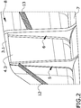
- the figure 2 shows a perspective view of a dorsal fin (11) structure illustrating the relationship between said dorsal fin (11) structure and the fuselage (7) of an aircraft (10).
- the dorsal fin (11) structure comprising frames (5, 6), upper support (3) and a skin (8) which is part of the rigid structure of said dorsal fin (11); and the fuselage (7) of the aircraft (10) comprising joining means (not shown).
- Figure 2 also shows how the first side (4.1) of the ballistic material layer (4) is arranged on the side A of the dorsal fin (11), and how is joined to the fuselage (7) and to the front and rear frames (5, 6).
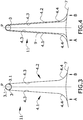
- Figure 3 shows schematically a cross sectional view of the dorsal fin (11) structure of the present invention and illustrates the relationship between said dorsal fin (11) and the fuselage (7) of an aircraft.
- Figure 3 also shows the sides (4.1, 4.2) of the ballistic material layer (4) distributed respectively on the sides A, B; both opposite sides attached to the fuselage (7) of the aircraft (10), and the ballistic material layer (4) being symmetrically relative to the vertical plane P.
- the upper support (3) is also shown being in contact with the ballistic material layer (4) by the sliding surface (3.1) of said upper support (3).
- a free space can be seen between both sides (4.1, 4.2) of the ballistic material layer (4), thus the internal surface (4.3) of said ballistic material layer (4) is in contact with the sliding surface (3.1) of the upper support (3).
- the external surface (4.4) of the ballistic material layer (4) is faced outward the dorsal fin (11) structure.
- Figure 4 shows schematically a particular embodiment wherein dorsal fin (11) structure further comprises an aerodynamic surface (9) being symmetrically relative to the vertical plane P.
- Said aerodynamic surface (9) is located around the ballistic material layer (4), and is arranged on both sides A, B of the dorsal fin (11) structure.
- the aerodynamic surface (9) is attached to the fuselage (7) of the aircraft (10).
- the aerodynamic skin (9) is also joined to the upper support (3) by fixing means (not shown), in such a way that said joint allows the ballistic material layer (4) slides around the upper support (3).
- the aerodynamic surface (9) is made of carbon fiber reinforcement plastic (CFRP) or metallic; for example, aluminum.
- CFRP carbon fiber reinforcement plastic
- the figures 5 and 6 show schematically behaves of the ballistic material layer (4) when an impact occurs on the side B of the dorsal fin (11) structure. Also, it can be seen a free space between the sides (4.1, 4.2) of the ballistic material layer.
- said side (4.2) works as a membrane absorbing the most part of the impact energy.
- the portion of the ballistic material layer (4) affected by the impact is progressively deflected, or even deformed, inward the dorsal fin (11) and also towards the first side (4.1) of the ballistic material layer (4).
- the impact occurred on the second side (4.2) causes that said second side (4.2) is deformed without reaching the first side (4.1) of the ballistic material layer (4).
- the impact occurred on the second side (4.2) causes that said second side (4.2) is deformed up to contacting with the opposite side (4.1) of the ballistic material layer (4).
- the impact energy is partially absorbed because of the friction between the sliding surface (3.1) of the upper support (3) and the internal surface (4.3) of the ballistic material layer (4) and the deformation of the ballistic material layer (4).
- the ballistic material layer (4) suffers an elastic deformation under tension in both sides (4.1, 4.2).
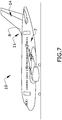
- Figure 7 shows an aircraft (10) comprising a dorsal fin (11) according to the present invention.
- the dorsal fin (11) is joined to the aircraft fuselage (7) and is joined to the vertical stabilizer (14) of said aircraft (10).
Landscapes
- Engineering & Computer Science (AREA)
- Aviation & Aerospace Engineering (AREA)
- Mechanical Engineering (AREA)
- Aiming, Guidance, Guns With A Light Source, Armor, Camouflage, And Targets (AREA)
- Laminated Bodies (AREA)
Claims (12)
- Structure de dérive dorsale (11) résistante aux impacts d'un aéronef (10) s'étendant le long d'une direction longitudinale X-X' et étant symétrique par rapport à un plan vertical P incluant la direction longitudinale X-X', le plan P présentant deux côtés A, B de chaque côté du plan vertical P dans la dérive dorsale (11), ladite dérive dorsale (11) étant adaptée pour être agencée sur un fuselage (7) de l'aéronef (10) et comprenant,
un support supérieur (3) à l'extrémité supérieure de la dérive dorsale (11), le support supérieur (3) comprenant une surface de glissement (3.1),
une couche de matériau balistique (4) pour absorber des impacts à haute énergie, la couche de matériau balistique (4) comprenantun premier côté (4.1) destiné à recevoir des impacts, ledit premier côté (4.1) étant agencé sur le côté A,un deuxième côté (4.2) destiné à recevoir des impacts, ledit deuxième côté (4.2) étant agencé sur le côté B et étant opposé au premier côté (4.1) par rapport au plan P, etune surface interne (4.3) tournée vers l'intérieur de la dérive dorsale (11) ;une ossature avant (5) comprenant un bord avant (5.1) sensiblement plan, et
une ossature arrière (6) comprenant un bord arrière (6.1) sensiblement plan, dans laquelle
l'ossature avant (5) et l'ossature arrière (6) supportant la couche de matériau balistique (4) et le support supérieur (3),
le premier côté (4.1) de la couche de matériau balistique (4) comprenant une première ligne de raccordement (1) et le côté opposé (4.2) comprenant une deuxième ligne de raccordement (2), de telle sorte que la couche de matériau balistique (4) est adaptée pour être reliée au fuselage (7) de l'aéronef (10) par ces lignes de raccordement (1,2), et
la surface interne (4.3) du matériau balistique (4) étant en contact avec la surface de glissement (3.1) du support supérieur (3), et ladite couche de matériau balistique (4) étant agencée de manière à pouvoir glisser autour de la surface de glissement (3.1) du support supérieur (3). - Structure de dérive dorsale (11) résistante aux impacts selon la revendication 1, dans laquelle la couche de matériau balistique (4) comprend une surface externe (4.4) destinée à recevoir l'impact.
- Structure de dérive dorsale (11) résistante aux impacts selon l'une quelconque des revendications précédentes, dans laquelle le bord avant (5.1) et le bord arrière (6.1) des ossatures avant (5) et arrière (6) comprennent respectivement une partie intermédiaire (5.4, 6.4) respective, qui sont destinées à ce que la couche balistique (4) glisse sur elles, et dans laquelle lesdites parties intermédiaires (5.4, 6.4) sont les extrémités supérieure de chaque ossature avant (5) et arrière (6) respectivement.
- Structure de dérive dorsale (11) résistante aux impacts selon la revendication 3, dans laquelle le matériau balistique (4) est relié au bord avant (5.1) et au bord arrière (6.1) de l'ossature avant (5) et de l'ossature arrière (6) respectivement, évitant la jonction entre ledit matériau balistique (4) et les parties intermédiaires (5.4, 6.4), de telle manière que ladite couche (4) du matériau balistique soit également agencée d'une façon glissante autour des parties intermédiaires (5.4, 6.4) des ossatures (5, 6) respectivement.
- Structure de dérive dorsale (11) résistante aux impacts selon les revendications 1 et 4, dans laquelle- la jonction entre la couche de matériau balistique (4) et le fuselage (7) de l'avion (10) est formée par des jonctions déchirables,- la jonction entre la couche de matériau balistique (4) et les bords avant et arrière (5.1, 6.1) des ossatures avant (5) et arrière (6), respectivement, est formée par des jonctions déchirables,- ou les deux ci-dessus.
- Structure de dérive dorsale (11) résistante aux impacts selon la revendication 5, dans laquelle l'une quelconque des jonctions déchirables est une ligne de rivets fusibles.
- Structure de dérive dorsale (11) résistante aux impacts selon l'une quelconque des revendications précédentes, dans laquelle l'ossature avant (5), l'ossature arrière (6) et la couche de matériau balistique (4) définissent un espace fermé.
- Structure de dérive dorsale résistante aux impacts (11) selon l'une quelconque des revendications précédentes,
comprenant en outre un espace libre entre le premier côté (4.1) et le deuxième côté (4.2) de la couche de matériau balistique (4), de sorte que la surface interne (4.3) d'un côté (4.1, 4.2) est adaptée à venir en contact avec la surface interne (4.3) du côté opposé (4.1, 4.2) si la couche de matériau balistique (4) est placée sous une contrainte élevée due à un impact. - Structure de dérive dorsale (11) résistante aux impacts selon l'une quelconque des revendications précédentes, comprenant en outre une surface aérodynamique (9) située autour de la couche de matériau balistique (4) laissant un espace libre entre elle-même (9) et ladite couche de matériau balistique (4), la surface aérodynamique (9) étant adaptée pour être jointe au fuselage (7) de l'aéronef.
- Structure de dérive dorsale résistante aux impacts selon l'une quelconque des revendications précédentes,
dans laquelle la couche de matériau balistique (4) est sous contrainte avant que ledit impact ne se produise. - Structure de dérive dorsale résistante aux impacts selon l'une quelconque des revendications 2 à 8, comprenant en outre un panneau à structure sandwich qui est relié à la couche de matériau balistique (4) par la surface externe (4.4) de cette couche de matériau balistique (4).
- Aéronef (10) comprenant une structure de dérive dorsale (11) selon l'une quelconque des revendications 1 à 11, dans lequel ladite dérive dorsale (11) est reliée au fuselage (7) de l'aéronef (10) et également à un stabilisateur vertical (14).
Priority Applications (2)
| Application Number | Priority Date | Filing Date | Title |
|---|---|---|---|
| EP16382619.1A EP3335986B1 (fr) | 2016-12-19 | 2016-12-19 | Dérive dorsale antichoc |
| US15/843,203 US10773790B2 (en) | 2016-12-19 | 2017-12-15 | Impact resistant dorsal fin |
Applications Claiming Priority (1)
| Application Number | Priority Date | Filing Date | Title |
|---|---|---|---|
| EP16382619.1A EP3335986B1 (fr) | 2016-12-19 | 2016-12-19 | Dérive dorsale antichoc |
Publications (2)
| Publication Number | Publication Date |
|---|---|
| EP3335986A1 EP3335986A1 (fr) | 2018-06-20 |
| EP3335986B1 true EP3335986B1 (fr) | 2019-11-20 |
Family
ID=57590452
Family Applications (1)
| Application Number | Title | Priority Date | Filing Date |
|---|---|---|---|
| EP16382619.1A Active EP3335986B1 (fr) | 2016-12-19 | 2016-12-19 | Dérive dorsale antichoc |
Country Status (2)
| Country | Link |
|---|---|
| US (1) | US10773790B2 (fr) |
| EP (1) | EP3335986B1 (fr) |
Families Citing this family (5)
| Publication number | Priority date | Publication date | Assignee | Title |
|---|---|---|---|---|
| JP6782533B2 (ja) * | 2015-08-26 | 2020-11-11 | 三菱航空機株式会社 | 航空機の前縁構造体、航空機の翼及び航空機 |
| US11518502B2 (en) * | 2019-04-30 | 2022-12-06 | Textron Innovations Inc. | Energy absorption stabilizers and methods |
| US11459085B2 (en) * | 2019-04-30 | 2022-10-04 | Textron Innovations Inc. | Energy attenuation stabilizers and methods |
| CN110539879A (zh) * | 2019-09-19 | 2019-12-06 | 中国航空工业集团公司西安飞机设计研究所 | 一种飞机的背鳍结构 |
| US20250214703A1 (en) * | 2023-12-29 | 2025-07-03 | Rtx Corporation | Blended wing body aircraft system |
Family Cites Families (9)
| Publication number | Priority date | Publication date | Assignee | Title |
|---|---|---|---|---|
| USH115H (en) * | 1986-02-03 | 1986-08-05 | The United States Of America As Represented By The Secretary Of The Navy | Arm restraint system for harness mounting |
| US6045096A (en) * | 1998-06-30 | 2000-04-04 | Rinn; Aaron | Variable camber airfoil |
| ES2197727B1 (es) * | 2000-07-27 | 2005-04-01 | Construcciones Aeronauticas, S.A. | Borde de ataque de superficies sustentadoras de aeronaves. |
| US7997529B2 (en) * | 2006-01-19 | 2011-08-16 | The Boeing Company | Compliant panel for aircraft |
| US8123167B2 (en) * | 2008-12-15 | 2012-02-28 | Embraer S.A. | Impact resistant aircraft leading edge structures and aircraft including the same |
| US20130001356A1 (en) * | 2011-07-01 | 2013-01-03 | Airbus Operations, S.L. | Reinforced aircraft fuselage |
| FR2989666B1 (fr) * | 2012-04-19 | 2014-12-05 | Eurocopter France | Surface aerodynamique portante d'aeronef, et aeronef muni de ladite surface aerodynamique portante |
| FR3000464B1 (fr) * | 2012-12-27 | 2016-01-15 | Eads Europ Aeronautic Defence | Dispositif d'absorption d'energie pour element de structure d'aeronef |
| FR3000463B1 (fr) * | 2012-12-27 | 2016-02-05 | Eads Europ Aeronautic Defence | Dispositif d'absorption d'energie pour element de structure d'aeronef |
-
2016
- 2016-12-19 EP EP16382619.1A patent/EP3335986B1/fr active Active
-
2017
- 2017-12-15 US US15/843,203 patent/US10773790B2/en active Active
Non-Patent Citations (1)
| Title |
|---|
| None * |
Also Published As
| Publication number | Publication date |
|---|---|
| US10773790B2 (en) | 2020-09-15 |
| EP3335986A1 (fr) | 2018-06-20 |
| US20180170520A1 (en) | 2018-06-21 |
Similar Documents
| Publication | Publication Date | Title |
|---|---|---|
| EP3335986B1 (fr) | Dérive dorsale antichoc | |
| CN104066647B (zh) | 冲击抵抗和损坏容限改善的飞行器机身段 | |
| US8434716B2 (en) | Compliant crown panel for an aircraft | |
| EP2196391B1 (fr) | Structures de surface portante d'avion résistantes aux impacts et avion l'incluant | |
| CN101687540B (zh) | 用于飞行器的适应性面板 | |
| US9359085B2 (en) | Aircraft with fuselage-mounted engines and an internal shield | |
| US9222368B2 (en) | Turbomachine casing assembly | |
| CN101977809B (zh) | 复合材料能量吸收结构零件和带有这类吸能器的航空器机身 | |
| EP3318481B1 (fr) | Structure de panneau pour aéronef et son procédé de fabrication | |
| Waimer et al. | Experimental study of CFRP components subjected to dynamic crash loads | |
| US10414497B2 (en) | Integrated detachable ballistic shield | |
| EP2620652B1 (fr) | Ensemble carter de turbomachine avec cavité de rétention d'aubes | |
| US9187170B2 (en) | Aircraft airfoil, and an aircraft provided with such an airfoil | |
| CA2940463A1 (fr) | Structure en materiau composite, aile d'aeronef et fuselage d'aeronef la comportant et procede de fabrication d'une structure en materiau composite | |
| US11597497B2 (en) | Leading edge structure for an aerodynamic surface of an aircraft | |
| US10882597B2 (en) | Impact resistant fuselage |
Legal Events
| Date | Code | Title | Description |
|---|---|---|---|
| PUAI | Public reference made under article 153(3) epc to a published international application that has entered the european phase |
Free format text: ORIGINAL CODE: 0009012 |
|
| STAA | Information on the status of an ep patent application or granted ep patent |
Free format text: STATUS: THE APPLICATION HAS BEEN PUBLISHED |
|
| AK | Designated contracting states |
Kind code of ref document: A1 Designated state(s): AL AT BE BG CH CY CZ DE DK EE ES FI FR GB GR HR HU IE IS IT LI LT LU LV MC MK MT NL NO PL PT RO RS SE SI SK SM TR |
|
| AX | Request for extension of the european patent |
Extension state: BA ME |
|
| STAA | Information on the status of an ep patent application or granted ep patent |
Free format text: STATUS: REQUEST FOR EXAMINATION WAS MADE |
|
| 17P | Request for examination filed |
Effective date: 20181218 |
|
| RBV | Designated contracting states (corrected) |
Designated state(s): AL AT BE BG CH CY CZ DE DK EE ES FI FR GB GR HR HU IE IS IT LI LT LU LV MC MK MT NL NO PL PT RO RS SE SI SK SM TR |
|
| RIC1 | Information provided on ipc code assigned before grant |
Ipc: B64C 5/06 20060101AFI20190305BHEP Ipc: B64C 3/28 20060101ALI20190305BHEP Ipc: B64D 45/00 20060101ALI20190305BHEP |
|
| GRAP | Despatch of communication of intention to grant a patent |
Free format text: ORIGINAL CODE: EPIDOSNIGR1 |
|
| STAA | Information on the status of an ep patent application or granted ep patent |
Free format text: STATUS: GRANT OF PATENT IS INTENDED |
|
| INTG | Intention to grant announced |
Effective date: 20190417 |
|
| GRAJ | Information related to disapproval of communication of intention to grant by the applicant or resumption of examination proceedings by the epo deleted |
Free format text: ORIGINAL CODE: EPIDOSDIGR1 |
|
| STAA | Information on the status of an ep patent application or granted ep patent |
Free format text: STATUS: REQUEST FOR EXAMINATION WAS MADE |
|
| INTC | Intention to grant announced (deleted) | ||
| GRAR | Information related to intention to grant a patent recorded |
Free format text: ORIGINAL CODE: EPIDOSNIGR71 |
|
| GRAS | Grant fee paid |
Free format text: ORIGINAL CODE: EPIDOSNIGR3 |
|
| STAA | Information on the status of an ep patent application or granted ep patent |
Free format text: STATUS: GRANT OF PATENT IS INTENDED |
|
| GRAA | (expected) grant |
Free format text: ORIGINAL CODE: 0009210 |
|
| STAA | Information on the status of an ep patent application or granted ep patent |
Free format text: STATUS: THE PATENT HAS BEEN GRANTED |
|
| INTG | Intention to grant announced |
Effective date: 20191007 |
|
| AK | Designated contracting states |
Kind code of ref document: B1 Designated state(s): AL AT BE BG CH CY CZ DE DK EE ES FI FR GB GR HR HU IE IS IT LI LT LU LV MC MK MT NL NO PL PT RO RS SE SI SK SM TR |
|
| REG | Reference to a national code |
Ref country code: GB Ref legal event code: FG4D |
|
| REG | Reference to a national code |
Ref country code: CH Ref legal event code: EP |
|
| REG | Reference to a national code |
Ref country code: DE Ref legal event code: R096 Ref document number: 602016024617 Country of ref document: DE |
|
| REG | Reference to a national code |
Ref country code: IE Ref legal event code: FG4D |
|
| REG | Reference to a national code |
Ref country code: AT Ref legal event code: REF Ref document number: 1203897 Country of ref document: AT Kind code of ref document: T Effective date: 20191215 |
|
| REG | Reference to a national code |
Ref country code: NL Ref legal event code: MP Effective date: 20191120 |
|
| REG | Reference to a national code |
Ref country code: LT Ref legal event code: MG4D |
|
| PG25 | Lapsed in a contracting state [announced via postgrant information from national office to epo] |
Ref country code: FI Free format text: LAPSE BECAUSE OF FAILURE TO SUBMIT A TRANSLATION OF THE DESCRIPTION OR TO PAY THE FEE WITHIN THE PRESCRIBED TIME-LIMIT Effective date: 20191120 Ref country code: LT Free format text: LAPSE BECAUSE OF FAILURE TO SUBMIT A TRANSLATION OF THE DESCRIPTION OR TO PAY THE FEE WITHIN THE PRESCRIBED TIME-LIMIT Effective date: 20191120 Ref country code: NO Free format text: LAPSE BECAUSE OF FAILURE TO SUBMIT A TRANSLATION OF THE DESCRIPTION OR TO PAY THE FEE WITHIN THE PRESCRIBED TIME-LIMIT Effective date: 20200220 Ref country code: GR Free format text: LAPSE BECAUSE OF FAILURE TO SUBMIT A TRANSLATION OF THE DESCRIPTION OR TO PAY THE FEE WITHIN THE PRESCRIBED TIME-LIMIT Effective date: 20200221 Ref country code: NL Free format text: LAPSE BECAUSE OF FAILURE TO SUBMIT A TRANSLATION OF THE DESCRIPTION OR TO PAY THE FEE WITHIN THE PRESCRIBED TIME-LIMIT Effective date: 20191120 Ref country code: LV Free format text: LAPSE BECAUSE OF FAILURE TO SUBMIT A TRANSLATION OF THE DESCRIPTION OR TO PAY THE FEE WITHIN THE PRESCRIBED TIME-LIMIT Effective date: 20191120 Ref country code: SE Free format text: LAPSE BECAUSE OF FAILURE TO SUBMIT A TRANSLATION OF THE DESCRIPTION OR TO PAY THE FEE WITHIN THE PRESCRIBED TIME-LIMIT Effective date: 20191120 Ref country code: BG Free format text: LAPSE BECAUSE OF FAILURE TO SUBMIT A TRANSLATION OF THE DESCRIPTION OR TO PAY THE FEE WITHIN THE PRESCRIBED TIME-LIMIT Effective date: 20200220 |
|
| PG25 | Lapsed in a contracting state [announced via postgrant information from national office to epo] |
Ref country code: HR Free format text: LAPSE BECAUSE OF FAILURE TO SUBMIT A TRANSLATION OF THE DESCRIPTION OR TO PAY THE FEE WITHIN THE PRESCRIBED TIME-LIMIT Effective date: 20191120 Ref country code: RS Free format text: LAPSE BECAUSE OF FAILURE TO SUBMIT A TRANSLATION OF THE DESCRIPTION OR TO PAY THE FEE WITHIN THE PRESCRIBED TIME-LIMIT Effective date: 20191120 Ref country code: IS Free format text: LAPSE BECAUSE OF FAILURE TO SUBMIT A TRANSLATION OF THE DESCRIPTION OR TO PAY THE FEE WITHIN THE PRESCRIBED TIME-LIMIT Effective date: 20200320 |
|
| PG25 | Lapsed in a contracting state [announced via postgrant information from national office to epo] |
Ref country code: AL Free format text: LAPSE BECAUSE OF FAILURE TO SUBMIT A TRANSLATION OF THE DESCRIPTION OR TO PAY THE FEE WITHIN THE PRESCRIBED TIME-LIMIT Effective date: 20191120 |
|
| PG25 | Lapsed in a contracting state [announced via postgrant information from national office to epo] |
Ref country code: DK Free format text: LAPSE BECAUSE OF FAILURE TO SUBMIT A TRANSLATION OF THE DESCRIPTION OR TO PAY THE FEE WITHIN THE PRESCRIBED TIME-LIMIT Effective date: 20191120 Ref country code: PT Free format text: LAPSE BECAUSE OF FAILURE TO SUBMIT A TRANSLATION OF THE DESCRIPTION OR TO PAY THE FEE WITHIN THE PRESCRIBED TIME-LIMIT Effective date: 20200412 Ref country code: EE Free format text: LAPSE BECAUSE OF FAILURE TO SUBMIT A TRANSLATION OF THE DESCRIPTION OR TO PAY THE FEE WITHIN THE PRESCRIBED TIME-LIMIT Effective date: 20191120 Ref country code: RO Free format text: LAPSE BECAUSE OF FAILURE TO SUBMIT A TRANSLATION OF THE DESCRIPTION OR TO PAY THE FEE WITHIN THE PRESCRIBED TIME-LIMIT Effective date: 20191120 Ref country code: ES Free format text: LAPSE BECAUSE OF FAILURE TO SUBMIT A TRANSLATION OF THE DESCRIPTION OR TO PAY THE FEE WITHIN THE PRESCRIBED TIME-LIMIT Effective date: 20191120 Ref country code: CZ Free format text: LAPSE BECAUSE OF FAILURE TO SUBMIT A TRANSLATION OF THE DESCRIPTION OR TO PAY THE FEE WITHIN THE PRESCRIBED TIME-LIMIT Effective date: 20191120 |
|
| REG | Reference to a national code |
Ref country code: CH Ref legal event code: PL |
|
| REG | Reference to a national code |
Ref country code: AT Ref legal event code: MK05 Ref document number: 1203897 Country of ref document: AT Kind code of ref document: T Effective date: 20191120 |
|
| REG | Reference to a national code |
Ref country code: DE Ref legal event code: R097 Ref document number: 602016024617 Country of ref document: DE |
|
| REG | Reference to a national code |
Ref country code: BE Ref legal event code: MM Effective date: 20191231 |
|
| PG25 | Lapsed in a contracting state [announced via postgrant information from national office to epo] |
Ref country code: MC Free format text: LAPSE BECAUSE OF FAILURE TO SUBMIT A TRANSLATION OF THE DESCRIPTION OR TO PAY THE FEE WITHIN THE PRESCRIBED TIME-LIMIT Effective date: 20191120 Ref country code: SK Free format text: LAPSE BECAUSE OF FAILURE TO SUBMIT A TRANSLATION OF THE DESCRIPTION OR TO PAY THE FEE WITHIN THE PRESCRIBED TIME-LIMIT Effective date: 20191120 Ref country code: SM Free format text: LAPSE BECAUSE OF FAILURE TO SUBMIT A TRANSLATION OF THE DESCRIPTION OR TO PAY THE FEE WITHIN THE PRESCRIBED TIME-LIMIT Effective date: 20191120 |
|
| PLBE | No opposition filed within time limit |
Free format text: ORIGINAL CODE: 0009261 |
|
| STAA | Information on the status of an ep patent application or granted ep patent |
Free format text: STATUS: NO OPPOSITION FILED WITHIN TIME LIMIT |
|
| 26N | No opposition filed |
Effective date: 20200821 |
|
| PG25 | Lapsed in a contracting state [announced via postgrant information from national office to epo] |
Ref country code: IE Free format text: LAPSE BECAUSE OF NON-PAYMENT OF DUE FEES Effective date: 20191219 Ref country code: LU Free format text: LAPSE BECAUSE OF NON-PAYMENT OF DUE FEES Effective date: 20191219 |
|
| PG25 | Lapsed in a contracting state [announced via postgrant information from national office to epo] |
Ref country code: BE Free format text: LAPSE BECAUSE OF NON-PAYMENT OF DUE FEES Effective date: 20191231 Ref country code: PL Free format text: LAPSE BECAUSE OF FAILURE TO SUBMIT A TRANSLATION OF THE DESCRIPTION OR TO PAY THE FEE WITHIN THE PRESCRIBED TIME-LIMIT Effective date: 20191120 Ref country code: CH Free format text: LAPSE BECAUSE OF NON-PAYMENT OF DUE FEES Effective date: 20191231 Ref country code: LI Free format text: LAPSE BECAUSE OF NON-PAYMENT OF DUE FEES Effective date: 20191231 Ref country code: SI Free format text: LAPSE BECAUSE OF FAILURE TO SUBMIT A TRANSLATION OF THE DESCRIPTION OR TO PAY THE FEE WITHIN THE PRESCRIBED TIME-LIMIT Effective date: 20191120 Ref country code: AT Free format text: LAPSE BECAUSE OF FAILURE TO SUBMIT A TRANSLATION OF THE DESCRIPTION OR TO PAY THE FEE WITHIN THE PRESCRIBED TIME-LIMIT Effective date: 20191120 |
|
| PG25 | Lapsed in a contracting state [announced via postgrant information from national office to epo] |
Ref country code: IT Free format text: LAPSE BECAUSE OF FAILURE TO SUBMIT A TRANSLATION OF THE DESCRIPTION OR TO PAY THE FEE WITHIN THE PRESCRIBED TIME-LIMIT Effective date: 20191120 |
|
| PG25 | Lapsed in a contracting state [announced via postgrant information from national office to epo] |
Ref country code: CY Free format text: LAPSE BECAUSE OF FAILURE TO SUBMIT A TRANSLATION OF THE DESCRIPTION OR TO PAY THE FEE WITHIN THE PRESCRIBED TIME-LIMIT Effective date: 20191120 |
|
| PG25 | Lapsed in a contracting state [announced via postgrant information from national office to epo] |
Ref country code: MT Free format text: LAPSE BECAUSE OF FAILURE TO SUBMIT A TRANSLATION OF THE DESCRIPTION OR TO PAY THE FEE WITHIN THE PRESCRIBED TIME-LIMIT Effective date: 20191120 Ref country code: HU Free format text: LAPSE BECAUSE OF FAILURE TO SUBMIT A TRANSLATION OF THE DESCRIPTION OR TO PAY THE FEE WITHIN THE PRESCRIBED TIME-LIMIT; INVALID AB INITIO Effective date: 20161219 |
|
| PG25 | Lapsed in a contracting state [announced via postgrant information from national office to epo] |
Ref country code: TR Free format text: LAPSE BECAUSE OF FAILURE TO SUBMIT A TRANSLATION OF THE DESCRIPTION OR TO PAY THE FEE WITHIN THE PRESCRIBED TIME-LIMIT Effective date: 20191120 |
|
| PG25 | Lapsed in a contracting state [announced via postgrant information from national office to epo] |
Ref country code: MK Free format text: LAPSE BECAUSE OF FAILURE TO SUBMIT A TRANSLATION OF THE DESCRIPTION OR TO PAY THE FEE WITHIN THE PRESCRIBED TIME-LIMIT Effective date: 20191120 |
|
| PGFP | Annual fee paid to national office [announced via postgrant information from national office to epo] |
Ref country code: DE Payment date: 20241210 Year of fee payment: 9 |
|
| PGFP | Annual fee paid to national office [announced via postgrant information from national office to epo] |
Ref country code: GB Payment date: 20241226 Year of fee payment: 9 |
|
| PGFP | Annual fee paid to national office [announced via postgrant information from national office to epo] |
Ref country code: FR Payment date: 20251229 Year of fee payment: 10 |