EP3336273B1 - Deckenmontiertes strahlungspanel - Google Patents
Deckenmontiertes strahlungspanel Download PDFInfo
- Publication number
- EP3336273B1 EP3336273B1 EP17207061.7A EP17207061A EP3336273B1 EP 3336273 B1 EP3336273 B1 EP 3336273B1 EP 17207061 A EP17207061 A EP 17207061A EP 3336273 B1 EP3336273 B1 EP 3336273B1
- Authority
- EP
- European Patent Office
- Prior art keywords
- panel
- support
- prominences
- channels
- longitudinal
- Prior art date
- Legal status (The legal status is an assumption and is not a legal conclusion. Google has not performed a legal analysis and makes no representation as to the accuracy of the status listed.)
- Active
Links
Images


Classifications
-
- F—MECHANICAL ENGINEERING; LIGHTING; HEATING; WEAPONS; BLASTING
- F24—HEATING; RANGES; VENTILATING
- F24D—DOMESTIC- OR SPACE-HEATING SYSTEMS, e.g. CENTRAL HEATING SYSTEMS; DOMESTIC HOT-WATER SUPPLY SYSTEMS; ELEMENTS OR COMPONENTS THEREFOR
- F24D3/00—Hot-water central heating systems
- F24D3/12—Tube and panel arrangements for ceiling, wall, or underfloor heating
- F24D3/16—Tube and panel arrangements for ceiling, wall, or underfloor heating mounted on, or adjacent to, a ceiling, wall or floor
- F24D3/165—Suspended radiant heating ceiling
-
- E—FIXED CONSTRUCTIONS
- E04—BUILDING
- E04B—GENERAL BUILDING CONSTRUCTIONS; WALLS, e.g. PARTITIONS; ROOFS; FLOORS; CEILINGS; INSULATION OR OTHER PROTECTION OF BUILDINGS
- E04B9/00—Ceilings; Construction of ceilings, e.g. false ceilings; Ceiling construction with regard to insulation
- E04B9/04—Ceilings; Construction of ceilings, e.g. false ceilings; Ceiling construction with regard to insulation comprising slabs, panels, sheets or the like
- E04B9/0421—Ceilings; Construction of ceilings, e.g. false ceilings; Ceiling construction with regard to insulation comprising slabs, panels, sheets or the like comprising ducts
-
- Y—GENERAL TAGGING OF NEW TECHNOLOGICAL DEVELOPMENTS; GENERAL TAGGING OF CROSS-SECTIONAL TECHNOLOGIES SPANNING OVER SEVERAL SECTIONS OF THE IPC; TECHNICAL SUBJECTS COVERED BY FORMER USPC CROSS-REFERENCE ART COLLECTIONS [XRACs] AND DIGESTS
- Y02—TECHNOLOGIES OR APPLICATIONS FOR MITIGATION OR ADAPTATION AGAINST CLIMATE CHANGE
- Y02B—CLIMATE CHANGE MITIGATION TECHNOLOGIES RELATED TO BUILDINGS, e.g. HOUSING, HOUSE APPLIANCES OR RELATED END-USER APPLICATIONS
- Y02B30/00—Energy efficient heating, ventilation or air conditioning [HVAC]
Definitions
- the present invention relates to a ceiling-mounted radiating panel for the heating and cooling of indoor spaces.
- Ceiling-mounted radiating panels of the so-called "sandwich type" are currently known which are preassembled and provided on a support made of SEP (sintered expanded polystyrene), which is known for its characteristics of very low heat conductivity, or made of other insulating materials, on which a multilayer pipe is fixed and/or inserted and on which a plasterboard panel is then glued.
- SEP sintered expanded polystyrene
- These panels are provided in modules of various sizes, substantially comprised in a range from 600 x 2,000 millimeters up to 1,200 x 2,400 millimeters.
- a further drawback resides in that said modular panels with plasterboard of the known type can reach a weight of even 15 kilograms per square meter, being thus particularly heavy, and make them difficult and laborious to handle and install on the part of the installation technicians, with a consequent increase in installation times and costs.
- ceiling-mounted radiating panels can use only tubes that have certain diameters, for example 14, 16, 17 millimeters.
- EP 1489241 A1 and US 5042570 are also known; the former, however, describes a panel intended only for thermal or acoustic insulation [as described in paragraph 0006 and in paragraph 0013] and not a radiating panel for the heating and cooling of indoor spaces.
- EP 1489241 A1 deals with a different technical problem, since for example it has no aim of providing a panel with high performance in terms of energy efficiency both in heating and in cooling; in fact, said panel is surrounded by metallic surfaces: its upper surface is in contact with the metal plate, while the lower and lateral surfaces are covered by the metallic covering in order to allow the support of the panel on an adjacent one by means of the magnetic strips that are recessed laterally in the sides of the fixing and supporting element, which in turn is associated with the metal plate.
- the panel is surrounded by metallic elements causes the panel to vary its temperature rapidly in response to variations in the external temperature or to a source of heating/cooling constituted by the duct, which is arranged in air between two sides of two adjacent panels; the panel therefore has high heat conductivity and low thermal resistance, characteristics which therefore make it unsuitable to be used as a radiating panel.
- the fixing and support system (in the sides of which the magnetic strips are recessed) is an element that is external to the panel and must be fixed beforehand to the metal plate by means of an adhesive, by welding, for example by laser welding, with screws, etc. [as described in paragraph 0022 from line 52 of page 4 to line 14 of page 5 of EP 1489241 A1 ].
- US 5042570 describes a metallic ceiling-mounted structure which comprises a metallic frame constituted by longitudinal girders and cross girders, which comprise tiles made of sheet metal which are suspended and comprise heat exchanger elements, comprising a pipe and a profiled guide, which are arranged above the tiles and are anchored to the guide by means of holding magnets [as described on page 1 from line 7 to line 12 and on page 5 from line 30 to line 44].
- US 5042570 does not describe a radiating panel with high performance in terms of energy efficiency in heating and in cooling, since the heat exchangers are in contact with metallic elements (the tiles) which cause a rapid variation in the temperature of the exchangers in response to a variation in the external temperature or to a source of heat/cooling constituted by the pipe.
- the aim of the present invention is to eliminate the drawbacks described above, providing a ceiling-mounted radiating panel that is self-supporting and has a high performance in terms of energy efficiency both in heating and in cooling.
- an object of the present invention is to obtain a ceiling-mounted radiating panel that can be modulated, has a continuous hydraulic circuit that has no connections between one panel and the other, reduces production costs and improves performance in terms of energy efficiency both in heating and in cooling.
- Another object of the invention is to have easy handling and installation thereof on the part of installation technicians and allow to reduce installation costs.
- Another object of the invention is to provide a ceiling-mounted radiating panel that allows to obtain a high thermal efficiency and a low thermal inertia.
- Another object is to devise a ceiling-mounted radiating panel that ensures high active surface coverage and high reliability.
- a further object is to obtain a ceiling-mounted radiating panel that adapts to various architectural requirements, can use pipes of diameters that are different from the ones that are used generally and can use various finishes.
- Another object is to obtain an invention that is structurally simple, has modest manufacturing costs, and can be provided with usual known systems and with traditional layout systems.
- a ceiling-mounted radiating panel particularly for heating and cooling indoor spaces, as defined in claim 1.
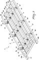
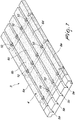
- the numeral 1 designates a ceiling-mounted radiating panel 2, particularly for the heating and cooling of indoor spaces.
- the panel 1 comprises a support 3 made of sintered expanded polystyrene (SEP), pure or mixed with insulating materials, such as for example graphite, adapted to improve the heat resistance of said panel 1.
- SEP sintered expanded polystyrene
- the support 3 advantageously has the chosen and appropriate shape and the chosen and appropriate dimensions depending on the specific requirements and in particular on the shape of the ceiling 2 to which it will be stably connected and of the walls adjacent thereto.
- the support 3 is substantially shaped like a parallelepiped.
- the support 3 has a lower surface 4 on which one or more longitudinal channels 5a, 5b, 5c, 5d are provided which run along the entire length of the lower surface 4 and are evenly mutually spaced.
- the lower surface 4 therefore has, laterally to each of said one or more channels 5a, 5b, 5c, 5d, a longitudinal prominence 6a, 6b, 6c, 6d, 6e, which is also extended along the entire length of the lower surface 4.
- the lower surface 4 therefore has, in a transverse cross-section, a substantially sinusoidal configuration.
- the number and dimensions of the one or more channels 5a, 5b, 5c, 5d and the spacing between them, and therefore the number and dimensions of the prominences 6a, 6b, 6c, 6d, 6e and their spacing, advantageously vary according to the specific requirements.
- the prominences 6a, 6e arranged at the lateral ends of the support 3, also known as outer prominences 6a, 6e, have, along a same transverse axis, a plurality of openings 7a, 7b, 7c, 7d, 7e, 7f which face each other in pairs and have such a depth as to have a bottom that lies at the bottom of each one of the one or more channels 5a, 5b, 5c, 5d.
- planar metallic blades 8a, 8b, 8c are stably arranged transversely to the lower surface 4, so as to affect in view the bottom of the one or more channels 5a, 5b, 5c, 5d and of the openings 7a, 7b, 7c, 7d, 7e, 7f, and are extended along the entire width of the support 3.
- Three metallic blades 8a, 8b, 8c have been designated by way of example in the illustrated solution.
- the metallic blades 8a, 8b, 8c pass through the prominences 6b, 6c, 6d interposed between the channels 5a, 5b, 5c, 5d, also known as inner prominences 6b, 6c, 6d, have a substantially rectangular plan shape and are preferably made of zinc-coated steel.
- the free ends 9a, 9b, 9c, 9d, 9e, 9f of the metallic blades 8a, 8b, 8c are accommodated in the openings 7a, 7b, 7c, 7d, 7e, 7f of the outer prominences 6a, 6e.
- the metallic blades 8a, 8b, 8c are adapted to support a plurality of fixing means 10, such as for example clips of the known type, which are associated stably with the metallic blades 8a, 8b, 8c by means of a chemical or mechanical system, such as for example a first screw 11.
- fixing means 10 such as for example clips of the known type
- the clips 10 are adapted to lock, by means of a simple pressure applied by the installation technician, a pipe 12 adapted to be arranged in the channels 5a, 5b, 5c, 5d and to surmount the inner prominences 6b, 6c, 6d with a curvature substantially of approximately 180° in transition from one channel to another.
- the metallic blades 8a, 8b, 8c are also adapted to fix the support 3 to longitudinal members 13 of a metallic supporting frame 14, which is stably connected to the ceiling 2.
- the fixing of the metallic blades 8a, 8b, 8c to the longitudinal members 13 occurs by means of a plurality of fixing elements, such as for example second screws 15, which are adapted to be arranged at the openings 7a, 7b, 7c, 7d, 7e, 7f of the outer prominences 6a, 6e of the support 3 so as to affect the ends 9a, 9b, 9c, 9d, 9e, 9f of the metallic blades 8a, 8b, 8c.
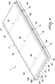
- a low-emissivity metallized film 16 is coupled stably and is adapted to improve the performance of the panel 1 both in terms of yield and in terms of thermal inertia.
- the support 3 is provided with a planar upper surface 17 that has, at the external longitudinal perimetric edges, a rabbet 18a, 18b which is extended along the entire length of the support 3.
- Each rabbet 18a, 18b is shaped complementarily with respect to the longitudinal members 13 of the metallic frame 14 mounted on the ceiling 2 and has a step-like shape which has a height that is substantially equal to the height of the longitudinal members 13 and a width that is substantially equal to approximately half the width of the longitudinal numbers 13, so that the longitudinal member 13 is accommodated in the two rabbets 18a, 18b of two laterally adjacent panels 1.
- a magnetic strip 19a, 19b is stably connected at each rabbet 18a, 18b by means of a double adhesive and is extended along the entire length of the support 3.
- the magnetic strip 19a, 19b has such a magnetic attraction and/or adhesion force as to keep the panel 1 fixed to the longitudinal members 13 of the frame 14 of the ceiling 2 during the positioning step.
- the panel 1 is applied to the ceiling 2 as described hereinafter.
- the support 3, on which the fixing means 10 have already been coupled beforehand, is associated initially by the installation technician with the longitudinal members 13 of the frame 14 of the ceiling 2 by means of the magnetic strips 19a, 19b associated with the rabbets 18a, 18b, which are shaped complementarily to the longitudinal members 13, and is permanently fixed stably also by means of the plurality of fixing elements 15, which are arranged at the openings 7a, 7b, 7c, 7d, 7e, 7f of the outer prominences 6a, 6e of the support 3.
- the installation technician then mates the pipe 12 with the fixing means 10, such as for example with the clips 10, by applying simple pressure.
- finishing panel which can have different finishes, such as plasterboard, wood, metal or heat-stretched sheet.
- the panel 1 is of the type that can be modulated and has a continuous hydraulic circuit, by virtue of the fact that it has a single pipe 12, therefore without discontinuities, which runs along the channels 5a, 5b, 5c, 5d of one or more panels 1 and passes from one channel to the other either by surmounting the inner prominences 6b, 6c, 6d of the panels 1 or by arranging itself at adapted seats shaped like an arc of substantially approximately 180°, which are provided at the inner prominences 6b, 6c, 6d.
- the panel 1 has no connections between one panel and the other by virtue of the rabbets 18a, 18b and the magnetic strips 19a, 19b associated therewith: the rabbets 18a, 18b of two side-by-side panels 1 in fact have a shape that is adapted to accommodate the longitudinal members 13 of the frame 14 mounted on the ceiling 2; the magnetic strips 19a, 19b associate the panels 1 with the longitudinal members 13 of the frame 14 mounted on the ceiling 2.
- the panel 1 improves performance in terms of energy efficiency both in heating and in cooling, by virtue of the absence of discontinuities in the hydraulic circuit, by virtue of the presence of the low-emissivity metallized film 16 at the lower surface 4 of the support 3, which is adapted to improve the performance of the panel 1 both in terms of yield and in terms of thermal inertia, and by virtue of the fact that the support 3 is preferably made of sintered expanded polystyrene (SEP), known for its very low heat conductivity characteristics, mixed with graphite, which improves the heat resistance of said panel 1.
- SEP sintered expanded polystyrene
- the panel 1 therefore allows to obtain a high thermal efficiency and a low thermal inertia.
- the panel 1 is easy to handle and install on the part of installation technicians, since the installation technician initially associates only the support 3, which is much lighter than the panels of the background art mounted with the insulating system, the pipe and the plasterboard, with the longitudinal numbers 13 of the frame 14 of the ceiling 2, and then couples the pipe 12 to the fixing means 10, such as for example to the clips 10, by applying a simple pressure, and finally couples the finishing panel.
- the panel 1 therefore allows quick and easy installation thereof, which reduces installation times and costs.
- the panel 1 ensures a high active surface covering and ensures higher reliability.
- the panel 1 is adapted to various architectural requirements, since the support 3 can easily assume the chosen shape by means of ad hoc shaping or cutting, can use pipes of diameters that are different from the ones generally used simply by choosing the fixing means 10 having the most appropriate dimensions, according to the specific requirements, and can use various finishes, such as for example plasterboard, wood, metal or heat-stretched sheet.
- the one or more longitudinal channels 5a, 5b, 5c, 5d that run along the entire length of the lower surface 4 and are mutually equidistant have, in transverse cross-section, such a width as to accommodate, between two of them, directly the fixing means 10 and the pipe 12, which can be arranged in said means; in this case, therefore, the prominences 6a, 6b, 6c, 6d, 6e have such a length as to be extended until they abut at the laterally adjacent fixing means 10.
- the one or more channels 5a, 5b, 5c, 5d thus form a seat for the positioning of the pipe 12.
- the lower surface 4 has a substantially planar shape.
Landscapes
- Engineering & Computer Science (AREA)
- Architecture (AREA)
- Physics & Mathematics (AREA)
- General Engineering & Computer Science (AREA)
- Combustion & Propulsion (AREA)
- Mechanical Engineering (AREA)
- Chemical & Material Sciences (AREA)
- Thermal Sciences (AREA)
- Electromagnetism (AREA)
- Civil Engineering (AREA)
- Structural Engineering (AREA)
- Central Heating Systems (AREA)
- Vehicle Interior And Exterior Ornaments, Soundproofing, And Insulation (AREA)
Claims (12)
- Ein Strahlungspanel (1), zu montieren an einer Decke (2), insbesondere zum Heizen und Kühlen von Innenräumen, wobei das Strahlungspanel (1) Folgendes umfasst:einen Träger (3), der im Wesentlichen aus gesintertem geschäumtem Polystyrol besteht,eine Vielzahl von Befestigungsmitteln (10) für eine Rohrleitung (12) undeinen metallischen Tragrahmen (14), der eine Vielzahl langgestreckter Glieder (13) umfasst, wobei eine Vielzahl von Metalllamellen (8a, 8b, 8c) quer zu dem Träger (3) fest positioniert ist, sowohl zum Tragen der Vielzahl von Befestigungsmitteln (10) als auch zum Befestigen des Trägers (3) an den langgestreckten Gliedern (13) des Rahmens (14);wobei an den äußeren länglichen Umfangskanten des Trägers (3) Anschlagleisten (18a, 18b) angebracht sind, mit denen ein Magnetstreifen (19a, 19b) fest verbunden ist; wobei die Anschlagleisten (18a, 18b) zur Verbindung des Trägers (3) mit dem Rahmen (14) komplementär zu den langgestreckten Gliedern (13) geformt sind.
- Das Panel (1) gemäß Anspruch 1, dadurch gekennzeichnet, dass der Träger (3) eine untere Oberfläche (4) hat, die in einem transversalen Querschnitt im Wesentlichen eine Sinuskonfiguration hat, um einen oder mehrere längliche Kanäle (5a, 5b, 5c, 5d) zu bilden, die zwischen einer oder mehreren länglichen Erhöhungen (6a, 6b, 6c, 6d, 6e) angeordnet sind, wobei beide sich über die gesamte Länge der unteren Oberfläche (4) erstrecken.
- Das Panel (1) gemäß Anspruch 2, dadurch gekennzeichnet, dass die Erhöhungen (6a, 6e), die an den seitlichen Enden des Trägers (3) angeordnet sind, auch als äußere Erhöhungen (6a, 6e) genannt, entlang einer selben Querachse eine Vielzahl von Öffnungen (7a, 7b, 7c, 7d, 7e, 7f) in einander gegenüberliegenden Paaren haben, die so tief sind, dass sie einen Boden haben, der am Boden jedes der einen oder mehreren Kanäle (5a, 5b, 5c, 5d) liegt.
- Das Panel (1) gemäß einem oder mehreren der obigen Ansprüche, dadurch gekennzeichnet, dass die planaren Metalllamellen (8a, 8b, 8c) quer zu der unteren Oberfläche (4) fest positioniert sind, um in der Sicht den Boden des einen oder der mehreren Kanäle (5a, 5b, 5c, 5d) und der Öffnungen (7a, 7b, 7c, 7d, 7e, 7f) zu beeinflussen, und sich über die gesamte Breite des Trägers (3) erstrecken; wobei die Metalllamellen (8a, 8b, 8c) durch die Erhöhungen (6b, 6c, 6d) verlaufen, die sich zwischen den Kanälen (5a, 5b, 5c, 5d) befinden, auch als innere Erhöhungen (6b, 6c, 6d) bezeichnet; wobei die Metalllamellen (8a, 8b, 8c) einen im Wesentlichen rechteckigen Grundriss haben, wobei die freien Enden (9a, 9b, 9c, 9d, 9e, 9f) der Metalllamellen (8a, 8b, 8c) in die Öffnungen (7a, 7b, 7c, 7d, 7e, 7f) der äußeren Erhöhungen (6a, 6e) eingeführt sind.
- Das Panel (1) gemäß einem oder mehreren der obigen Ansprüche, dadurch gekennzeichnet, dass die Befestigungsmittel (10) über ein chemisches oder mechanisches System (11) fest mit den Metalllamellen (8a, 8b, 8c) verbunden und ausgebildet sind, um die Rohrleitung (12) zu blockieren, die wiederum ausgebildet ist, um an den Kanälen (5a, 5b, 5c, 5d) angeordnet zu werden und um die inneren Erhöhungen (6b, 6c, 6d) zu überragen mit einer Krümmung von im Wesentlichen 180° im Übergang von einem der Kanäle zu einem anderen der Kanäle, oder alternativ sich an geeigneten Sitzen anordnend, die wie ein Bogen von im Wesentlichen 180° geformt sind, angebracht an den inneren Erhöhungen (6b, 6c, 6d) zum Zwecke des Übergangs von einem der Kanäle zu einem anderen der Kanäle.
- Das Panel (1) gemäß einem oder mehreren der obigen Ansprüche, dadurch gekennzeichnet, dass die Metalllamellen (8a, 8b, 8c) ausgebildet sind, um den Träger (3) an den langgestreckten Gliedern (13) zu befestigen, die den Tragrahmen (14) bilden, der metallisch und fest mit der Decke (2) verbunden ist; wobei die Befestigung der Metalllamellen (8a, 8b, 8c) an den langgestreckten Gliedern (13) mit Hilfe einer Vielzahl von Befestigungselementen (15) stattfindet, die ausgebildet sind, um an den Öffnungen (7a, 7b, 7c, 7d, 7e, 7f) der äußeren Erhöhungen (6a, 6e) des Trägers (3) angeordnet zu werden, um so die Enden (9a, 9b, 9c, 9d, 9e, 9f) der Metalllamellen (8a, 8b, 8c) zu beeinflussen.
- Das Panel (1) gemäß einem oder mehreren der obigen Ansprüche, dadurch gekennzeichnet, dass ein Metallfilm (16) mit niedrigem Emissionsvermögen fest mit der gesamten unteren Oberfläche (4) des Trägers (3) verbunden ist, ausgenommen der Bereich, der die Befestigungsmittel (10) und die Öffnungen (7a, 7b, 7c, 7d, 7e, 7f) der äußeren Erhöhungen (6a, 6e) umgibt; und ausgebildet ist, um die Leistung des Panels (1) sowohl im Hinblick auf Ausbeute als auch auf Wärmeträgheit zu verbessern.
- Das Panel (1) gemäß Anspruch 1, dadurch gekennzeichnet, dass der Träger (3) eine planare obere Oberfläche (17) hat, die an den äußeren länglichen Umfangskanten mit den Anschlagleisten (18a, 18b) versehen ist und sich über die gesamte Länge des Trägers (3) erstreckt, wobei jede der Anschlagleisten (18a, 18b) eine stufenartige Form mit einer Höhe hat, die im Wesentlichen gleich der Höhe der langgestreckten Glieder (13) ist, und einer Breite, die im Wesentlichen gleich der halben Breite der langgestreckten Glieder (13) ist, so dass das langgestreckte Glied (13) in zwei der Anschlagleisten (18a, 18b) von zwei der nebeneinander angeordneten Panels (1) untergebracht ist.
- Das Panel (1) gemäß Anspruch 1, dadurch gekennzeichnet, dass der Magnetstreifen (19a, 19b), der sich über die gesamte Länge des Trägers (3) erstreckt, über einen doppelten Klebstoff fest mit jeder der Anschlagleisten (18a, 18b) verbunden und mit dem Rahmen (14) fest über ein magnetisches Befestigungssystem verbunden ist, das genügend Anziehungs- und/oder Adhäsionskraft hat, um das Panel (1) während des Positionierschritts befestigt zu halten.
- Das Panel (1) gemäß Anspruch 1, dadurch gekennzeichnet, dass der Träger (3) aus gesintertem geschäumtem Polystyrol, gemischt mit Graphit, besteht.
- Das Panel (1) gemäß einem oder mehreren der obigen Ansprüche, dadurch gekennzeichnet, dass der Träger (3) zunächst, sobald die Befestigungsmittel (10) damit gekoppelt wurden, mit den langgestreckten Gliedern (13) des Rahmens (14) durch die Magnetstreifen (19a, 19b) verbunden werden kann, die magnetisch mit den Anschlagleisten (18a, 18b) verbunden sind, welche komplementär zu den langgestreckten Gliedern (13) geformt sind; wobei der Träger (3) an den langgestreckten Gliedern (13) auch durch Befestigungselemente (15) befestigt wird, welche an den Öffnungen (7a, 7b, 7c, 7d, 7e, 7f) der äußeren Erhöhungen (6a, 6e) des Trägers (3) angebracht sind; wobei die Rohrleitung (12) anschließend mit dem Befestigungsmitteln (10) verbindbar ist, wobei danach ein Verblendpanel mit der unteren Oberfläche (4) des Panels (1) verbindbar ist.
- Das Panel (1) gemäß Anspruch 1, dadurch gekennzeichnet, dass der Träger (3) eine untere Oberfläche (4) hat, die in einem transversalen Querschnitt eine im Wesentlichen planare Form hat, auf welcher ein oder mehrere längliche Kanäle (5a, 5b, 5c, 5d) angebracht sind, die einen Sitz für die Befestigungsmittel (10) und die Rohrleitung (12) bilden.
Priority Applications (1)
| Application Number | Priority Date | Filing Date | Title |
|---|---|---|---|
| PL17207061T PL3336273T3 (pl) | 2016-12-16 | 2017-12-13 | Montowany do stropu panel promiennikowy |
Applications Claiming Priority (1)
| Application Number | Priority Date | Filing Date | Title |
|---|---|---|---|
| IT102016000127254A IT201600127254A1 (it) | 2016-12-16 | 2016-12-16 | Pannello radiante a soffitto |
Publications (2)
| Publication Number | Publication Date |
|---|---|
| EP3336273A1 EP3336273A1 (de) | 2018-06-20 |
| EP3336273B1 true EP3336273B1 (de) | 2020-07-01 |
Family
ID=58455561
Family Applications (1)
| Application Number | Title | Priority Date | Filing Date |
|---|---|---|---|
| EP17207061.7A Active EP3336273B1 (de) | 2016-12-16 | 2017-12-13 | Deckenmontiertes strahlungspanel |
Country Status (3)
| Country | Link |
|---|---|
| EP (1) | EP3336273B1 (de) |
| IT (1) | IT201600127254A1 (de) |
| PL (1) | PL3336273T3 (de) |
Families Citing this family (1)
| Publication number | Priority date | Publication date | Assignee | Title |
|---|---|---|---|---|
| FR3110616B1 (fr) | 2020-05-19 | 2022-11-25 | Rehau Tube Sarl | Plafond rayonnant reversible et procede d’assemblage d’un tel plafond |
Family Cites Families (6)
| Publication number | Priority date | Publication date | Assignee | Title |
|---|---|---|---|---|
| IT1040180B (it) * | 1975-07-29 | 1979-12-20 | Pirelli | Pannello per il rivestimento di sofpitti |
| DE3921719A1 (de) * | 1989-07-01 | 1991-01-10 | Wilhelmi Werke Gmbh & Co Kg | Deckenverkleidung |
| EP1489241A1 (de) * | 2003-06-20 | 2004-12-22 | Schneider Dämmtechnik AG | Anordnung zum Befestigen von Deckenelementen |
| FR2875520B1 (fr) * | 2004-09-20 | 2007-05-25 | Structures Fixations Panneaux | Panneau modulaire pour revetement de surface |
| US20120125562A1 (en) * | 2010-11-18 | 2012-05-24 | Basf Se | Method for the continuous production of composite elements for use as a radiant ceiling panel |
| DE102014014828A1 (de) * | 2014-10-09 | 2016-04-14 | BeKa Heiz- und Kühlmatten GmbH | Kunststoffrohrmatte mit magnetisch wirkenden Elementen |
-
2016
- 2016-12-16 IT IT102016000127254A patent/IT201600127254A1/it unknown
-
2017
- 2017-12-13 EP EP17207061.7A patent/EP3336273B1/de active Active
- 2017-12-13 PL PL17207061T patent/PL3336273T3/pl unknown
Non-Patent Citations (1)
| Title |
|---|
| None * |
Also Published As
| Publication number | Publication date |
|---|---|
| IT201600127254A1 (it) | 2018-06-16 |
| EP3336273A1 (de) | 2018-06-20 |
| PL3336273T3 (pl) | 2021-01-25 |
Similar Documents
| Publication | Publication Date | Title |
|---|---|---|
| CA2840790C (en) | Modular panel for thermal energy transfer | |
| US8474514B2 (en) | Carrier structure for partitioning and/or inner partitioning with integrated heating and/or cooling | |
| US20050076600A1 (en) | Thermal wall system | |
| US9410706B2 (en) | Modular heating structure that can be fitted to the interior walls of buildings | |
| CN219713482U (zh) | 一种空调器 | |
| US7617648B2 (en) | Thermal framing component | |
| EP3336273B1 (de) | Deckenmontiertes strahlungspanel | |
| CN102575855B (zh) | 炕取暖板组装体 | |
| US8656905B2 (en) | Air channeling baffle for a furnace heat exchanger | |
| JP5305333B2 (ja) | 冷暖房パネル | |
| JP3570587B2 (ja) | 天井放射冷暖房設備 | |
| JP4042971B2 (ja) | 冷暖房空気オンドル構造 | |
| EP1703215A1 (de) | Aluminium Strahlungsplatte für eine Unterdecke | |
| EP2783767A1 (de) | Rohrförmige gerippte Spule für den Durchgang einer Übertragungsflüssigkeit für Strahlungspaneele für decken-, wand- oder bodenmontierte Klimaregelungssysteme, und Verfahren zu dessen Bereitstellung | |
| CN220580289U (zh) | 一种近零能耗建筑遮阳组合式格栅 | |
| CN222687674U (zh) | 一种装配式成品耐火风管 | |
| TWI687570B (zh) | 可更換板材之牆 | |
| CN221280029U (zh) | 风冷式板翅式散热器 | |
| US20230008608A1 (en) | Radiant ceiling panel and method of manufacturing the same | |
| CN218937123U (zh) | 一种双侧吸热的散热器 | |
| CN218818950U (zh) | 一种网孔板式隔热层 | |
| RU100816U1 (ru) | Конвектор | |
| EP4600595A1 (de) | Heizkörper | |
| CN210463544U (zh) | 一种空调及其换热器组件 | |
| CN213420175U (zh) | 一种无甲醛消音复合风管 |
Legal Events
| Date | Code | Title | Description |
|---|---|---|---|
| PUAI | Public reference made under article 153(3) epc to a published international application that has entered the european phase |
Free format text: ORIGINAL CODE: 0009012 |
|
| STAA | Information on the status of an ep patent application or granted ep patent |
Free format text: STATUS: THE APPLICATION HAS BEEN PUBLISHED |
|
| AK | Designated contracting states |
Kind code of ref document: A1 Designated state(s): AL AT BE BG CH CY CZ DE DK EE ES FI FR GB GR HR HU IE IS IT LI LT LU LV MC MK MT NL NO PL PT RO RS SE SI SK SM TR |
|
| AX | Request for extension of the european patent |
Extension state: BA ME |
|
| STAA | Information on the status of an ep patent application or granted ep patent |
Free format text: STATUS: REQUEST FOR EXAMINATION WAS MADE |
|
| 17P | Request for examination filed |
Effective date: 20181024 |
|
| RBV | Designated contracting states (corrected) |
Designated state(s): AL AT BE BG CH CY CZ DE DK EE ES FI FR GB GR HR HU IE IS IT LI LT LU LV MC MK MT NL NO PL PT RO RS SE SI SK SM TR |
|
| STAA | Information on the status of an ep patent application or granted ep patent |
Free format text: STATUS: EXAMINATION IS IN PROGRESS |
|
| 17Q | First examination report despatched |
Effective date: 20190523 |
|
| GRAP | Despatch of communication of intention to grant a patent |
Free format text: ORIGINAL CODE: EPIDOSNIGR1 |
|
| STAA | Information on the status of an ep patent application or granted ep patent |
Free format text: STATUS: GRANT OF PATENT IS INTENDED |
|
| INTG | Intention to grant announced |
Effective date: 20200110 |
|
| GRAS | Grant fee paid |
Free format text: ORIGINAL CODE: EPIDOSNIGR3 |
|
| GRAA | (expected) grant |
Free format text: ORIGINAL CODE: 0009210 |
|
| STAA | Information on the status of an ep patent application or granted ep patent |
Free format text: STATUS: THE PATENT HAS BEEN GRANTED |
|
| AK | Designated contracting states |
Kind code of ref document: B1 Designated state(s): AL AT BE BG CH CY CZ DE DK EE ES FI FR GB GR HR HU IE IS IT LI LT LU LV MC MK MT NL NO PL PT RO RS SE SI SK SM TR |
|
| REG | Reference to a national code |
Ref country code: AT Ref legal event code: REF Ref document number: 1286311 Country of ref document: AT Kind code of ref document: T Effective date: 20200715 Ref country code: CH Ref legal event code: EP |
|
| REG | Reference to a national code |
Ref country code: IE Ref legal event code: FG4D |
|
| REG | Reference to a national code |
Ref country code: DE Ref legal event code: R096 Ref document number: 602017018956 Country of ref document: DE |
|
| REG | Reference to a national code |
Ref country code: LT Ref legal event code: MG4D |
|
| PG25 | Lapsed in a contracting state [announced via postgrant information from national office to epo] |
Ref country code: BG Free format text: LAPSE BECAUSE OF FAILURE TO SUBMIT A TRANSLATION OF THE DESCRIPTION OR TO PAY THE FEE WITHIN THE PRESCRIBED TIME-LIMIT Effective date: 20201001 |
|
| REG | Reference to a national code |
Ref country code: NL Ref legal event code: MP Effective date: 20200701 |
|
| PG25 | Lapsed in a contracting state [announced via postgrant information from national office to epo] |
Ref country code: GR Free format text: LAPSE BECAUSE OF FAILURE TO SUBMIT A TRANSLATION OF THE DESCRIPTION OR TO PAY THE FEE WITHIN THE PRESCRIBED TIME-LIMIT Effective date: 20201002 Ref country code: NO Free format text: LAPSE BECAUSE OF FAILURE TO SUBMIT A TRANSLATION OF THE DESCRIPTION OR TO PAY THE FEE WITHIN THE PRESCRIBED TIME-LIMIT Effective date: 20201001 Ref country code: FI Free format text: LAPSE BECAUSE OF FAILURE TO SUBMIT A TRANSLATION OF THE DESCRIPTION OR TO PAY THE FEE WITHIN THE PRESCRIBED TIME-LIMIT Effective date: 20200701 Ref country code: LT Free format text: LAPSE BECAUSE OF FAILURE TO SUBMIT A TRANSLATION OF THE DESCRIPTION OR TO PAY THE FEE WITHIN THE PRESCRIBED TIME-LIMIT Effective date: 20200701 Ref country code: PT Free format text: LAPSE BECAUSE OF FAILURE TO SUBMIT A TRANSLATION OF THE DESCRIPTION OR TO PAY THE FEE WITHIN THE PRESCRIBED TIME-LIMIT Effective date: 20201102 Ref country code: HR Free format text: LAPSE BECAUSE OF FAILURE TO SUBMIT A TRANSLATION OF THE DESCRIPTION OR TO PAY THE FEE WITHIN THE PRESCRIBED TIME-LIMIT Effective date: 20200701 Ref country code: CZ Free format text: LAPSE BECAUSE OF FAILURE TO SUBMIT A TRANSLATION OF THE DESCRIPTION OR TO PAY THE FEE WITHIN THE PRESCRIBED TIME-LIMIT Effective date: 20200701 Ref country code: SE Free format text: LAPSE BECAUSE OF FAILURE TO SUBMIT A TRANSLATION OF THE DESCRIPTION OR TO PAY THE FEE WITHIN THE PRESCRIBED TIME-LIMIT Effective date: 20200701 Ref country code: ES Free format text: LAPSE BECAUSE OF FAILURE TO SUBMIT A TRANSLATION OF THE DESCRIPTION OR TO PAY THE FEE WITHIN THE PRESCRIBED TIME-LIMIT Effective date: 20200701 |
|
| PG25 | Lapsed in a contracting state [announced via postgrant information from national office to epo] |
Ref country code: IS Free format text: LAPSE BECAUSE OF FAILURE TO SUBMIT A TRANSLATION OF THE DESCRIPTION OR TO PAY THE FEE WITHIN THE PRESCRIBED TIME-LIMIT Effective date: 20201101 Ref country code: LV Free format text: LAPSE BECAUSE OF FAILURE TO SUBMIT A TRANSLATION OF THE DESCRIPTION OR TO PAY THE FEE WITHIN THE PRESCRIBED TIME-LIMIT Effective date: 20200701 Ref country code: RS Free format text: LAPSE BECAUSE OF FAILURE TO SUBMIT A TRANSLATION OF THE DESCRIPTION OR TO PAY THE FEE WITHIN THE PRESCRIBED TIME-LIMIT Effective date: 20200701 |
|
| PG25 | Lapsed in a contracting state [announced via postgrant information from national office to epo] |
Ref country code: NL Free format text: LAPSE BECAUSE OF FAILURE TO SUBMIT A TRANSLATION OF THE DESCRIPTION OR TO PAY THE FEE WITHIN THE PRESCRIBED TIME-LIMIT Effective date: 20200701 |
|
| REG | Reference to a national code |
Ref country code: DE Ref legal event code: R097 Ref document number: 602017018956 Country of ref document: DE |
|
| PG25 | Lapsed in a contracting state [announced via postgrant information from national office to epo] |
Ref country code: DK Free format text: LAPSE BECAUSE OF FAILURE TO SUBMIT A TRANSLATION OF THE DESCRIPTION OR TO PAY THE FEE WITHIN THE PRESCRIBED TIME-LIMIT Effective date: 20200701 Ref country code: EE Free format text: LAPSE BECAUSE OF FAILURE TO SUBMIT A TRANSLATION OF THE DESCRIPTION OR TO PAY THE FEE WITHIN THE PRESCRIBED TIME-LIMIT Effective date: 20200701 Ref country code: SM Free format text: LAPSE BECAUSE OF FAILURE TO SUBMIT A TRANSLATION OF THE DESCRIPTION OR TO PAY THE FEE WITHIN THE PRESCRIBED TIME-LIMIT Effective date: 20200701 |
|
| PLBE | No opposition filed within time limit |
Free format text: ORIGINAL CODE: 0009261 |
|
| STAA | Information on the status of an ep patent application or granted ep patent |
Free format text: STATUS: NO OPPOSITION FILED WITHIN TIME LIMIT |
|
| PG25 | Lapsed in a contracting state [announced via postgrant information from national office to epo] |
Ref country code: AL Free format text: LAPSE BECAUSE OF FAILURE TO SUBMIT A TRANSLATION OF THE DESCRIPTION OR TO PAY THE FEE WITHIN THE PRESCRIBED TIME-LIMIT Effective date: 20200701 |
|
| 26N | No opposition filed |
Effective date: 20210406 |
|
| PG25 | Lapsed in a contracting state [announced via postgrant information from national office to epo] |
Ref country code: SK Free format text: LAPSE BECAUSE OF FAILURE TO SUBMIT A TRANSLATION OF THE DESCRIPTION OR TO PAY THE FEE WITHIN THE PRESCRIBED TIME-LIMIT Effective date: 20200701 |
|
| REG | Reference to a national code |
Ref country code: CH Ref legal event code: PL |
|
| PG25 | Lapsed in a contracting state [announced via postgrant information from national office to epo] |
Ref country code: MC Free format text: LAPSE BECAUSE OF FAILURE TO SUBMIT A TRANSLATION OF THE DESCRIPTION OR TO PAY THE FEE WITHIN THE PRESCRIBED TIME-LIMIT Effective date: 20200701 Ref country code: SI Free format text: LAPSE BECAUSE OF FAILURE TO SUBMIT A TRANSLATION OF THE DESCRIPTION OR TO PAY THE FEE WITHIN THE PRESCRIBED TIME-LIMIT Effective date: 20200701 |
|
| REG | Reference to a national code |
Ref country code: BE Ref legal event code: MM Effective date: 20201231 |
|
| PG25 | Lapsed in a contracting state [announced via postgrant information from national office to epo] |
Ref country code: LU Free format text: LAPSE BECAUSE OF NON-PAYMENT OF DUE FEES Effective date: 20201213 Ref country code: IE Free format text: LAPSE BECAUSE OF NON-PAYMENT OF DUE FEES Effective date: 20201213 |
|
| PG25 | Lapsed in a contracting state [announced via postgrant information from national office to epo] |
Ref country code: CH Free format text: LAPSE BECAUSE OF NON-PAYMENT OF DUE FEES Effective date: 20201231 Ref country code: LI Free format text: LAPSE BECAUSE OF NON-PAYMENT OF DUE FEES Effective date: 20201231 |
|
| PG25 | Lapsed in a contracting state [announced via postgrant information from national office to epo] |
Ref country code: TR Free format text: LAPSE BECAUSE OF FAILURE TO SUBMIT A TRANSLATION OF THE DESCRIPTION OR TO PAY THE FEE WITHIN THE PRESCRIBED TIME-LIMIT Effective date: 20200701 Ref country code: MT Free format text: LAPSE BECAUSE OF FAILURE TO SUBMIT A TRANSLATION OF THE DESCRIPTION OR TO PAY THE FEE WITHIN THE PRESCRIBED TIME-LIMIT Effective date: 20200701 Ref country code: CY Free format text: LAPSE BECAUSE OF FAILURE TO SUBMIT A TRANSLATION OF THE DESCRIPTION OR TO PAY THE FEE WITHIN THE PRESCRIBED TIME-LIMIT Effective date: 20200701 |
|
| PG25 | Lapsed in a contracting state [announced via postgrant information from national office to epo] |
Ref country code: MK Free format text: LAPSE BECAUSE OF FAILURE TO SUBMIT A TRANSLATION OF THE DESCRIPTION OR TO PAY THE FEE WITHIN THE PRESCRIBED TIME-LIMIT Effective date: 20200701 |
|
| REG | Reference to a national code |
Ref country code: DE Ref legal event code: R082 Ref document number: 602017018956 Country of ref document: DE Representative=s name: SCHIEBER - FARAGO PATENTANWAELTE, DE Ref country code: DE Ref legal event code: R082 Ref document number: 602017018956 Country of ref document: DE Representative=s name: FARAGO PATENTANWALTSGESELLSCHAFT MBH, DE |
|
| PG25 | Lapsed in a contracting state [announced via postgrant information from national office to epo] |
Ref country code: BE Free format text: LAPSE BECAUSE OF NON-PAYMENT OF DUE FEES Effective date: 20201231 |
|
| REG | Reference to a national code |
Ref country code: DE Ref legal event code: R082 Ref document number: 602017018956 Country of ref document: DE Representative=s name: SCHIEBER - FARAGO PATENTANWAELTE, DE |
|
| P01 | Opt-out of the competence of the unified patent court (upc) registered |
Effective date: 20230527 |
|
| REG | Reference to a national code |
Ref country code: AT Ref legal event code: UEP Ref document number: 1286311 Country of ref document: AT Kind code of ref document: T Effective date: 20200701 |
|
| PGFP | Annual fee paid to national office [announced via postgrant information from national office to epo] |
Ref country code: DE Payment date: 20251212 Year of fee payment: 9 |
|
| PGFP | Annual fee paid to national office [announced via postgrant information from national office to epo] |
Ref country code: GB Payment date: 20251215 Year of fee payment: 9 |
|
| PGFP | Annual fee paid to national office [announced via postgrant information from national office to epo] |
Ref country code: AT Payment date: 20251212 Year of fee payment: 9 |
|
| PGFP | Annual fee paid to national office [announced via postgrant information from national office to epo] |
Ref country code: IT Payment date: 20251120 Year of fee payment: 9 |
|
| PGFP | Annual fee paid to national office [announced via postgrant information from national office to epo] |
Ref country code: FR Payment date: 20251215 Year of fee payment: 9 |
|
| PGFP | Annual fee paid to national office [announced via postgrant information from national office to epo] |
Ref country code: PL Payment date: 20251128 Year of fee payment: 9 |
|
| PGFP | Annual fee paid to national office [announced via postgrant information from national office to epo] |
Ref country code: RO Payment date: 20251209 Year of fee payment: 9 |