EP3336285B1 - Ensembles verrou de fermeture - Google Patents
Ensembles verrou de fermeture Download PDFInfo
- Publication number
- EP3336285B1 EP3336285B1 EP17206762.1A EP17206762A EP3336285B1 EP 3336285 B1 EP3336285 B1 EP 3336285B1 EP 17206762 A EP17206762 A EP 17206762A EP 3336285 B1 EP3336285 B1 EP 3336285B1
- Authority
- EP
- European Patent Office
- Prior art keywords
- latching
- housing
- latch assembly
- handle
- latch
- Prior art date
- Legal status (The legal status is an assumption and is not a legal conclusion. Google has not performed a legal analysis and makes no representation as to the accuracy of the status listed.)
- Active
Links
Images


Classifications
-
- E—FIXED CONSTRUCTIONS
- E05—LOCKS; KEYS; WINDOW OR DOOR FITTINGS; SAFES
- E05C—BOLTS OR FASTENING DEVICES FOR WINGS, SPECIALLY FOR DOORS OR WINDOWS
- E05C1/00—Fastening devices with bolts moving rectilinearly
- E05C1/08—Fastening devices with bolts moving rectilinearly with latching action
- E05C1/12—Fastening devices with bolts moving rectilinearly with latching action with operating handle or equivalent member moving otherwise than rigidly with the latch
-
- E—FIXED CONSTRUCTIONS
- E05—LOCKS; KEYS; WINDOW OR DOOR FITTINGS; SAFES
- E05B—LOCKS; ACCESSORIES THEREFOR; HANDCUFFS
- E05B63/00—Locks or fastenings with special structural characteristics
- E05B63/14—Arrangement of several locks or locks with several bolts, e.g. arranged one behind the other
-
- E—FIXED CONSTRUCTIONS
- E05—LOCKS; KEYS; WINDOW OR DOOR FITTINGS; SAFES
- E05B—LOCKS; ACCESSORIES THEREFOR; HANDCUFFS
- E05B15/00—Other details of locks; Parts for engagement by bolts of fastening devices
- E05B15/02—Striking-plates; Keepers; Bolt staples; Escutcheons
- E05B15/0205—Striking-plates, keepers, staples
-
- E—FIXED CONSTRUCTIONS
- E05—LOCKS; KEYS; WINDOW OR DOOR FITTINGS; SAFES
- E05B—LOCKS; ACCESSORIES THEREFOR; HANDCUFFS
- E05B5/00—Handles completely let into the surface of the wing
-
- E—FIXED CONSTRUCTIONS
- E05—LOCKS; KEYS; WINDOW OR DOOR FITTINGS; SAFES
- E05B—LOCKS; ACCESSORIES THEREFOR; HANDCUFFS
- E05B5/00—Handles completely let into the surface of the wing
- E05B5/006—Handles completely let into the surface of the wing essentially defining a completely closed surface together with the wing
-
- E—FIXED CONSTRUCTIONS
- E05—LOCKS; KEYS; WINDOW OR DOOR FITTINGS; SAFES
- E05B—LOCKS; ACCESSORIES THEREFOR; HANDCUFFS
- E05B63/00—Locks or fastenings with special structural characteristics
- E05B63/14—Arrangement of several locks or locks with several bolts, e.g. arranged one behind the other
- E05B63/143—Arrangement of several locks, e.g. in parallel or series, on one or more wings
-
- E—FIXED CONSTRUCTIONS
- E05—LOCKS; KEYS; WINDOW OR DOOR FITTINGS; SAFES
- E05B—LOCKS; ACCESSORIES THEREFOR; HANDCUFFS
- E05B9/00—Lock casings or latch-mechanism casings ; Fastening locks or fasteners or parts thereof to the wing
-
- E—FIXED CONSTRUCTIONS
- E05—LOCKS; KEYS; WINDOW OR DOOR FITTINGS; SAFES
- E05C—BOLTS OR FASTENING DEVICES FOR WINGS, SPECIALLY FOR DOORS OR WINDOWS
- E05C1/00—Fastening devices with bolts moving rectilinearly
- E05C1/08—Fastening devices with bolts moving rectilinearly with latching action
- E05C1/12—Fastening devices with bolts moving rectilinearly with latching action with operating handle or equivalent member moving otherwise than rigidly with the latch
- E05C1/14—Fastening devices with bolts moving rectilinearly with latching action with operating handle or equivalent member moving otherwise than rigidly with the latch the handle or member moving essentially towards or away from the plane of the wing or frame
- E05C1/145—Fastening devices with bolts moving rectilinearly with latching action with operating handle or equivalent member moving otherwise than rigidly with the latch the handle or member moving essentially towards or away from the plane of the wing or frame flush
-
- E—FIXED CONSTRUCTIONS
- E05—LOCKS; KEYS; WINDOW OR DOOR FITTINGS; SAFES
- E05B—LOCKS; ACCESSORIES THEREFOR; HANDCUFFS
- E05B15/00—Other details of locks; Parts for engagement by bolts of fastening devices
- E05B15/02—Striking-plates; Keepers; Bolt staples; Escutcheons
- E05B15/0205—Striking-plates, keepers, staples
- E05B2015/023—Keeper shape
- E05B2015/0235—Stud-like
-
- E—FIXED CONSTRUCTIONS
- E05—LOCKS; KEYS; WINDOW OR DOOR FITTINGS; SAFES
- E05B—LOCKS; ACCESSORIES THEREFOR; HANDCUFFS
- E05B15/00—Other details of locks; Parts for engagement by bolts of fastening devices
- E05B15/04—Spring arrangements in locks
- E05B2015/0403—Wound springs
- E05B2015/0406—Wound springs wound in a cylindrical shape
- E05B2015/0413—Wound springs wound in a cylindrical shape loaded by compression
-
- E—FIXED CONSTRUCTIONS
- E05—LOCKS; KEYS; WINDOW OR DOOR FITTINGS; SAFES
- E05B—LOCKS; ACCESSORIES THEREFOR; HANDCUFFS
- E05B15/00—Other details of locks; Parts for engagement by bolts of fastening devices
- E05B15/04—Spring arrangements in locks
- E05B2015/0486—A single spring working on more than one element
Definitions
- the subject matter disclosed herein generally relates to latch assemblies and, more particularly, to latch assemblies for opening and closing openable structures.
- Existing latches for closures are configured to close with minimal effort. That is, minimal effort is needed to be expended by a user to operate a locking/latching mechanism to open an openable structure (e.g., a closure, door, panel, etc.). Accordingly, a user can operate the latch assembly to open or close (and secure) the openable structure with ease when a latch lever is operated (e.g., pulled, rotated, lifted, etc.).
- a plunger assembly is provided to be operated by a handle. The plunger assembly can move relative to a securing feature (e.g., a latch catch or locking bracket) to secure the latch assembly and thus secure the openable structure in a closed position.
- a securing feature e.g., a latch catch or locking bracket
- latch assemblies may be subject to reliability issues over time and may fail to open or close as intended during usage. This degraded performance can result from continued use over the life of the latch assembly. As such, frequent replacement of the latch assembly and/or portions thereof may be
- multiple latches such as a dual latch may be employed with openable structures to provide additional functionality and/or securing.
- a dual latch can provide securing at multiple locations on an openable structure.
- operation of one of the two latches can be operated and the other of the two latches will operate in tandem. That is, a dual latch can provide functionality of both latches by operation of only one of the latches.
- the dual latch may not always close or open after continuous usage for a period of time (e.g., fatigue).
- GB 2283277 A discloses a locking mechanism comprising a pair of locking jaws adapted to receive a locking bar.
- the jaws are retained in a housing on a door frame whereas the locking bar is mounted on a door.
- the locking bar In a locked configuration the locking bar is retained by the jaws and can only be released by manual operation to effect movement of the bar along its longitudinal axis.
- In a released configuration the jaws In a released configuration the jaws are separated by a cam to permit the locking bar to move in a direction perpendicular to its longitudinal axis and out of the housing through an entry slot.
- US 7,497,103 B1 and US 6 145 352 A both disclose latches having a pair of oppositely acting latch bolts slidable on a housing that are engageable with latching formations on a strike.
- latch assemblies for opening and closing openable structures are provided.
- the latch assemblies include a housing defining a cavity, a handle movably mounted to the housing, and a latching mechanism in the cavity and disposed between the handle and the housing.
- the latching mechanism includes at least one guide pin mounted to the housing, a first body movable along the at least one guide pin, the first body having a first latching element extending through the housing, a second body movable along the at least one guide pin, the second body having a second latching element extending through the housing, a first link attached to the first body, a second link attached to the second body, and a link connector operably connecting the first link to the second link, wherein movement of the link connector urges the first latching element and the second latching element apart through movement of the first link and the second link and the first body and the second body.
- latch assembly may include an actuation arm fixedly connected to the handle such that movement of the handle causes movement of the link connector.
- latch assembly may include a cover installed between the handle and the latching mechanism within the cavity, the cover configured to cover the first body and the second body.
- further embodiments of the latch assembly may include that the cover includes at least one cover guiding structure, the cover guiding structure configured to guide movement of the link connector.
- latch assembly may include that the cover includes an actuation slot where the actuation arm passes through the cover to interact with the link connector.
- further embodiments of the latch assembly may include that the housing includes at least one housing guiding structure, the housing guiding structure configured to guide movement of the link connector.
- further embodiments of the latch assembly may include at least one biasing member disposed on the at least one guide pin and configured to urge the first body toward the second body along the at least one guide pin.
- further embodiments of the latch assembly may include that the at least one biasing member comprises a first biasing member disposed between the first body and the housing and a second biasing member disposed between the second body and the housing.
- further embodiments of the latch assembly may include a locking bracket configured to receive the first latching member and the second latching member to secure the latching members in a first state.
- further embodiments of the latch assembly may include that the locking bracket includes a catch arm, the catch arm having at least one stop surface configured to receive the first latching element and the second latching element to secure the first and second latching elements in the first state.
- further embodiments of the latch assembly may include that the catch arm further includes a spreading surface configured to spread the first latching member apart from the second latching member when the latch assembly is moved into the first state.
- each of the first latching element and the second latching element comprise a complementary engagement surface that engages with and runs along the spreading surface of the catch arm.
- further embodiments of the latch assembly may include that a portion of the catch arm has a width and, in the first state, the first and second latching elements are separated by a first separation distance that is less than the width of the catch arm, and, in a second state, the first and second latching elements are separated by a second separation distance that is greater than the width of the catch arm such that the first and second latching elements can move freely relative to the catch arm.
- the latch assemblies include a housing defining a cavity, a handle movably mounted to the housing, and a latching mechanism in the cavity and disposed between the handle and the housing.
- the latching mechanism includes at least one guide pin mounted to the housing, a first body movable along the at least one guide pin, the first body having a first latching element extending through the housing and having an inclined surface, a second body movable along the at least one guide pin, the second body having a second latching element extending through the housing and having an inclined surface, a movable wedge positioned between the inclined surfaces of the first body and the second body, and an actuation arm fixedly connected to the handle such that movement of the handle causes movement of the movable wedge, wherein movement of the movable wedge urges the first latching element and the second latching element apart through movement of the first body and the second body spread by the movable wedge along the inclined surfaces.
- openable structures with a latch assembly for opening and closing openable structures include a frame, a closure body movable relative to the frame, and a first latch assembly at least partially installed to the closure body.
- the first latch assembly includes a housing defining a cavity, the housing fixedly attached to the closure body, a handle movably mounted to the housing, and a latching mechanism in the cavity and disposed between the handle and the housing.
- the latching mechanism includes at least one guide pin mounted to the housing, a first body movable along the at least one guide pin, the first body having a first latching element extending through the housing, a second body movable along the at least one guide pin, the second body having a second latching element extending through the housing, a first link attached to the first body, a second link attached to the second body, and a link connector operably connecting the first link to the second link, wherein movement of the link connector urges the first latching element and the second latching element apart through movement of the first link and the second link and the first body and the second body.
- further embodiments of the openable structure may include a locking bracket mounted to the frame and configured to receive the first latching member and the second latching member to secure the latching members in a first state such that the closure body is secured within the frame.
- further embodiments of the openable structure may include that the locking bracket includes a catch arm, the catch arm having at least one stop surface configured to receive the first latching element and the second latching element to secure the first and second latching elements in the first state.
- further embodiments of the openable structure may include that the catch arm further includes a spreading surface configured to spread the first latching member apart from the second latching member when the latch assembly is moved into the first state.
- further embodiments of the openable structure may include that a portion of the catch arm has a width and the first and second latching elements are separated by a first separation distance that is less than the width of the catch and the first and second latching elements are separated by a second separation distance that is greater than the width of the catch such that the first and second latching elements can move freely relative to the catch arm.
- further embodiments of the openable structure may include a second latch assembly, wherein the first and second latch assemblies are operably connected to operate synchronously upon operating of one of the first or second latch assemblies.
- latch assemblies having multiple bodies operably connected, each body having a latching element to ensure proper latching and provide increased latch life. Further technical effects include assembly connectors to operably connect multiple latch assemblies to enable synchronous operation of the multiple latch assemblies.
- FIGS. 1A-1C are schematic illustrations of an openable structure and latching assembly in a traditional configuration.
- FIG. 1A is a schematic illustration of an openable structure 101 having two latching mechanisms 103 (labeled 103a, 103b in FIG. 1A ).
- the openable structure 101 is a door, hatch, panel, or other openable and closable structure having a closure body 101a that can be operated and movable, in part, by operation of one or both of the latching mechanisms 103.
- the closure body 101a fixedly attaches to a frame 101b when in a closed and secured stated.
- the closure body 101a is movable (e.g., slidable, rotatable, pivotable, etc.) with respect to the frame 101b.
- the latching mechanisms 103 can be manually operated by a person that desires to open or close the openable structure 101. In a first position the latching mechanisms 103 can be engaged and securely retain the closure body 101a in a closed position and in a second position the latching mechanisms 103 can be disengaged and enable the openable structure 101 to be opened (or closed). That is, in the second position of the latching mechanisms 103, the closure body 101a can be moved between a closed position and an open position.
- FIG. 1B schematically illustrates one of the latching mechanisms 103 in the first position
- FIG. 1C schematically illustrates the latching mechanism 103 in the second position
- the latching mechanism 103 includes a handle 105 that is operably and/or movably connected to a plunger 107 by a lever arm 109.
- the plunger 107 is configured to engage with or contact a catch 111.
- the catch 111 may be an integral part or portion of the closure body 101a and/or the openable structure 101 or may be a separate element that is fixedly connected to or otherwise attached to the closure body 101a and/or the openable structure 101.
- the plunger 107 can be a bar, rod, plate, or other physical structure that, when in the first position (FIG. IB), contacts or engages with the catch 111 to secure the latching mechanism 103 and thus the openable structure 101 in a closed state.
- the handle when a user manually operates the handle 105, the handle can rotate (as shown as curved dashed arrow in FIG. 1C ) and operate the lever arm 109 in a downward manner (as shown as dashed arrow in FIG. 1C ).
- the lever arm 109 moves downward it pulls the plunger 107 downward such that the plunger 107 clears the catch 111 and the latching mechanism 103 can be pulled outward to open the openable structure 101.
- the reverse operation can be used to close the openable structure 101 and allow the plunger 107 to secure behind the catch 111 and lock or secure the openable structure 101 in the closed position.
- latching mechanisms as shown and described in FIGS. 1A-1C can be used in various settings, and in one non-limiting example, can be used for aircraft closures within a cabin.
- the latching mechanisms can be used to secure foldable seats, doors of cabinets and cubbies for storage, or other openable structures within an aircraft cabin. Because the openable structures may be located on an aircraft, ensuring proper closure and securing is an important consideration.
- use of latching mechanisms as shown in FIGS. 1A-1C over time, can degrade, and thus the latching aspect may not be as secure as desired, needed, or required.
- FIGS. 2A-2I schematic illustrations of a latch assembly 200 in accordance with an embodiment of the present disclosure are shown.
- FIGS. 2A-2I illustrate various components of the latch assembly 200 and the operation thereof.
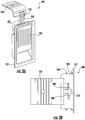
- FIG. 2A is a front perspective illustration of the latch assembly 200 as assembled.
- the latch assembly 200 includes a handle 202, a housing 204, a first latching element 206, and a second latching element 208.
- the handle 202 fits within a cavity 210 defined within the housing 204.
- FIG. 2B is a rear perspective illustration of the latch assembly 200 as assembled.
- FIG. 2C is a side view illustration indicating operation of a handle 202 of the latch assembly 200.
- FIG. 2D is a rear view isometric illustration of the handle 202.
- FIG. 2E is a schematic illustration of the latch assembly 200 with the handle 202 removed and illustrating a cover 212.
- FIG. 2F is an illustration of the cover 212 separated from the latch assembly 200.
- FIG. 2G is a schematic illustration of the housing 204 with interior elements removed therefrom.
- FIGS. 2H-2I are schematic illustrations of a latching mechanism 214 shown outside of the housing 204, the latching mechanism 214 including the first latching element 206 and the second latching element 208.
- the latch assembly 200 includes the handle 202, the housing 204, and the latching mechanism 214 installed therein.
- the housing 204 can be configured to install within or to a portion of an openable structure (e.g., openable structure 101 shown in FIG. 1A ). In some embodiments, the housing 204 can be configured to fit flush or smooth with a surface of the openable structure or closure body in which the housing 204 is installed.
- the housing 204 can be formed of any material, and in some embodiments may be, but is not limited to, metallic, plastics, and/or composite materials.
- the housing 204 defines the cavity 210 into which the latching mechanism 214 is installed. The cavity 210 is configured to receive the latching mechanism 214 and the handle 202.
- first and second latching elements 206, 208 extend through a portion of the housing 204, such as the top, although the first and second latching elements 206, 208 can extend through any side of the housing without departing from the scope of the present disclosure.
- the first and second latching elements 206, 208 extend from the housing 204 to enable engagement with a catch or locking bracket (e.g., as shown in FIGS. 3A-3F and FIGS. 4A-4B ).
- Configurations of the housing 204 can include various features.
- the housing can include one or more mounting apertures 216, connection apertures 218 (as described below), and one or more latching element apertures 220.
- the housing 204 may further include one or more features or elements to enable receiving and retaining the latching mechanism 214 and the handle 202 therein.
- the housing 204 can receive a handle pin 222 that enables the handle 202 to pivot thereabout, as illustrated by the arrow in FIG. 2C .
- the housing 204 can be configured to receive one or more guide pins 224 (as shown, a single guide pin 224 is employed) that is configured to guide movement of the latching elements 206, 208 within the housing 204.
- a single guide pin 224 can be provided for each separate body (e.g., bodies 234, 236 described herein).
- multiple guide pins can be positioned at various locations on and/or in the bodies such that each body is guided by multiple guide pins.
- a single, shorter guide pin can be configured for each body separately.
- the guide pins can include stops, flanges, or other structure on one end to retain the bodies on the guide pins.
- the handle 202 includes an actuation arm 226 that is fixedly connected to or integrally formed with the handle 202.
- the actuation arm 226 is configured to move with movement of the handle 202 such that the actuation arm 226 can actuate or otherwise operate the latching mechanism 214, as described herein.
- the actuation arm 226 moves therewith, such that a portion of the actuation arm 226 moves relative to the housing 204 (e.g., downward).
- the movement is a tilting of the actuation arm 226 as the handle 202 is operated.
- the actuation arm 226 can move within an actuation slot 228 of the cover 212.
- the cover 212 is fixedly mounted within the cavity 210 of the housing 204. As shown in FIG. 2E , the cover 212 can cover or otherwise protect or shield the latching mechanism 214, as will be appreciated through the illustrations of FIGS. 2A-2I . For example, at least a portion of the latching mechanism 214 is retained or otherwise contained between the housing 204 and the cover 212 within the cavity 210. Because the latching mechanism 214 is covered by the cover 212, the cover 212 includes the actuation slot 228 to enable the actuation arm 226 to interact with a portion of the latching mechanism 214.
- the cover 212 can include one or more optional cover guiding structures 230.
- the cover guiding structures 230 are configured to guide the actuation arm 226 and/or a portion of the latching mechanism 214, as described herein.
- FIG. 2G shows the housing 204 with no components installed therein.
- the housing 204 includes the mounting apertures 216 to enable installation of the housing 204 into an openable structure, such as by fastener (e.g., screws, nails, rivet, bolts, etc.).
- the mounting apertures 216 may be optional in some configurations, and may not be included depending on the mounting/installation of the housing 204 into an openable structure.
- the housing 204 includes optional connection apertures 218 that can enable connection between two or more latch assemblies 200, as described herein.
- the housing 204 can include optional housing guiding structures 232.
- the housing guiding structures 232 can act similarly to the cover guiding structures 230 of the cover 212, and can function in concert therewith in embodiments where both the cover guiding structures 230 and the housing guiding structures 232 are included.
- the latching mechanism 214 includes the first latching element 206 and the second latching element 208.
- the first latching element 206 extends from a first body 234 and the second latching element 208 extends from a second body 236.
- the latching elements 206, 208 are integrally formed or part of the respective body 234, 236.
- the latching elements 206, 208 can be fixedly attached or connected to the respective body 234, 236, without departing from the scope of the present disclosure.
- the two bodies 234, 236 are moveable relative to each other along the guide pin 224 which passes through a portion of each of the bodies 234, 236.
- the guide pin 224 can fixedly install into the housing 204 (e.g., as shown in FIGS. 2A-2C ) and thus movably retain the bodies 234, 236 within the cavity 210 of the housing 204.
- the guide pin 224 can be fixed relative to the housing 204 such that the guide pin 224 does not move within the housing 204.
- the two bodies 234, 236 can be operably connected by a link assembly 238.
- the link assembly 238 includes a first link 240 that is rotatably and/or pivotably connected to the first body 234 and a second link 242 that is rotatably and/or pivotably connected to the second body 236.
- the first link 240 and the second link 242 are connected or attached by a link connector 244.
- the link connector 244 is connected to the first and second links 240, 242 such that movement of the link connector 244 causes both of the first and second links 240, 242 to move therewith, such as when the actuation arm 226 presses against the link connector 244.
- the two links 240, 242 will each move (e.g., pivot, rotate, etc.).
- the respective bodies 234, 236 move as well. That is, the bodies 234, 236 are urged to move by movement of the respective links 240, 242 in response to movement of the link connector 244.
- the links 240, 242 are moved (e.g., a spreading motion) and the two bodies 234, 236 move away from each other along the guide pin 224.
- the link connector 244 can be guided between guide structures of the housing and/or of the cover (e.g., housing guide structures 232 and/or cover guide structures 230).
- a channel may be formed between guide structures to ensure only vertical movement of the link connector 244 and to prevent lateral or sideways movement of the link connector 244.
- the guide pin 224 has first and second biasing members 246, 248.
- the biasing members 246, 248 are configured to be located on the guide pin 224 and each positioned between a portion of one of the bodies 234, 236 and a portion of the housing 204. Accordingly, the biasing members 246, 248 are configured to bias the two bodies 234, 236 toward each other. That is, the bodies 234, 236 are movable within the housing 204 along the guide pin 224 and the housing 204 is stationary. Thus, when the link assembly 238 is operated to move the two bodies 234, 236 apart, the bodies 234, 236 act to compress the respective biasing member 246, 248.
- a biasing member can be fixedly connected between the first and second bodies, along the guide pin, and may be configured to pull the two bodies toward each other, and operation of the link assembly will expand the biasing member in such configuration.
- the biasing feature may be integrally formed or a characteristic of the link members, the link connector, and/or other part of the link assembly.
- FIGS. 3A-3F schematic illustrations of a latch assembly 300 in accordance with an embodiment of the present disclosure are shown.
- FIGS. 3A-3F illustrate operation or actuation and use of the latch assembly 300.
- the latch assembly 300 is substantially similar to that shown and described with respect to FIGS. 2A-2I . That is, the latch assembly 300 includes a handle 302, a housing 304, and a latching mechanism 314 ( FIG. 3E ) is housed within the housing 304 and operable by operation of the handle 302.
- the latching mechanism 314 includes a first latching element 306 and a second latching element 308 that extend out of the housing 304.
- the latching elements 306, 308 are configured to operate with a locking bracket 350 that includes a catch arm 352.
- housing 304 and elements contained therein and as part thereof can be fixedly connected to an openable structure and/or closure body (as described above) and the locking bracket 350 can be fixedly connected to a separate structure, such as a frame or wall in which the openable structure opens and closes.
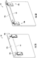
- FIG. 3A is a perspective illustration of the latch assembly 300 in a first (e.g., locked or latched) state and FIG. 3B is a top down, plan view illustration of the latch assembly 300 in the first state.
- FIG. 3C is a perspective illustration of the latch assembly 300 in a second (e.g., unlocked or unlatched) state and FIG. 3D is a top down, plan view illustration of the latch assembly 300 in the second state.
- FIG. 3E is a perspective illustration of the latch assembly 300 with the housing 304 and a cover removed to illustrate the components of the latching mechanism 314 in the second state.
- FIG. 3F is a top down, plan view illustration of the locking bracket 350.
- the latch assembly 300 includes the complementary locking bracket 350 (e.g., part or integral with frame 101b) which includes the catch arm 352 that extends from the locking bracket 350.
- the latching elements 306, 308 are engaged with the catch arm 352 of the locking bracket 350 to thus prevent movement of the housing 304 relative to the locking bracket 350.
- the catch arm 352 includes a first stop surface 354 and a second stop surface 356 that are configured to stop or catch respective latching elements 306, 308 from in a direction away from the locking bracket 350.
- the handle 302 is flush or within the housing 304.
- the first and second latching elements 306, 308 are positioned behind the respective first and second stop surfaces 354, 356. As such, when in the first state, the latching elements 306, 308 are prevented from movement in a direction away from the locking bracket 350 (e.g., to the right in the illustration). Also, as noted above, the latching elements 306, 308 are attached to the bodies of the latching mechanism 314 which can be biased toward each other, and thus the latching elements 306, 308 will not move away from the catch arm 352 (e.g., up and down in the illustration). As such, the latching elements 306, 308 will securely hold and retain a closure body relative to the locking bracket 350.
- the latch assembly 300 is shown in the second (e.g., unlocked or unlatched) state.
- the handle 302 is pulled out from or raised away from the housing 304 about a handle pin 322.
- an actuation arm 326 is moved to contact and/or apply force to a link connector 344 of the latching mechanism 314 (e.g., as described above).
- the link connector 344 operates on links of the latching mechanism 314 to thus urge two bodies apart (as described above).
- the bodies move apart along a guide pin 324.
- the first and second latching elements 306, 308 move away from each other.
- the separation between the first and second latching elements 306, 308 can be increased to a separation distance that is greater than a width dimension of the catch arm 352 such that the first and second latching elements 306, 308 can move freely past the catch arm 352 and enabling movement (e.g., opening) of a openable structure in which the latch assembly 300 is installed or connected.
- the openable structure e.g., closure body such as a panel or door
- the openable structure can be closed.
- the latching elements 306, 308 will contact the catch arm 352.
- the catch arm 352 includes a spreading surface 358 that is curved, contoured, or otherwise shaped such that as the latching elements 306, 308 contact the spreading surface 358 the two latching elements 306, 308 spread apart or separate a sufficient distance such that the latching elements 306, 308 can move toward the locking bracket 350 and move into position to contact the stop surfaces 354, 356.
- FIGS. 4A-4B schematic illustrations of the interaction of latching elements 406, 408 with respect to a locking bracket 450 are shown.
- FIG. 4A is an illustration of the latching elements 406, 408 in the first state (e.g., locked, latched, secured, etc.) and
- FIG. 4B is an illustration of the latching elements 406, 408 spread such that the latching elements 406, 408 can move past a catch arm 452.
- the catch arm 452 has a width W.
- the latching elements 406, 408 are separated by a first separation distance D1 that is less than the width W of the catch arm 452, as shown in FIG. 4A .
- the latching elements 406, 408 are forced to spread apart to a second separation distance D2.
- the second separation distance D2 is greater than the width W of the catch arm 452, and thus the latching elements 406, 408 can freely move past the catch arm 452 to open an openable structure that the latching elements 406, 408 and locking bracket 450 are part of.
- the catch arm 452 includes a spreading surface 458 and stop surfaces 454, 456.
- the latching elements 406, 408 can include respective, complementary engagement surfaces 406a, 408a.
- the complementary engagement surfaces 406a, 408a are contours or curved surfaces of the respective latching elements 406, 408 that enable ease of spreading of the latching elements 406, 408 when moving from an open position of the closure body to a closed position of the closure body (e.g., as the latching elements 406, 408 move along the spreading surface 458).
- the latching elements 406, 408 can include complementary stop surfaces 406b, 408b that can engage with the stop surfaces 454, 456 of the catch arm 452 to provide secure engagement and locking of a closure body in a closed state.
- two or more latch assemblies may be desired.
- the openable structure may be sufficiently large to require more than a single latch assembly to securely retain the openable structure in a closed state.
- FIGS. 5A-5D an openable structure 501 having a closure body 501a and multiple latch assemblies 500a, 500b in accordance with an embodiment of the present disclosure is shown.
- FIG. 5A is a front perspective illustration of the closure body 501a transparently shown to illustrate an assembly connector 560 between a first latch assembly 500a and a second latch assembly 500b.
- the latch assemblies 500a, 500b are substantially similar to the latch assemblies shown and described above, and thus similar features and structures will not be described again.
- Each of the latch assemblies 500a, 500b includes a handle, a housing, and a latching mechanism within the housing.
- FIG. 5B is a rear perspective illustration of the openable structure 501.
- the latch assemblies 500a, 500b are connected by the assembly connector 560 to operate synchronously or in tandem when one of the two latch assemblies 500a, 500b is operated. That is, operation of the first latch assembly 500a will cause operation of the second latch assembly 500b such that the closure body 501a can be opened (and vice versa).
- FIG. 5C is a schematic illustration showing the assembly connector 560 and the latch assemblies 500a, 500b in more detail.
- the first latch assembly 500a includes a first body 534a and a second body 536a, with each body having a respective latching element extending therefrom.
- the second latch assembly 500b includes a first body 534b and a second body 536b, with each both having a respective latching element extending therefrom. It is noted that the first body 534a, 534b of each latch assembly 500a, 500b is located in the same position within the respective latch assembly 500a, 500b.
- each first body 534a, 534b is located to the left within the respective latch assembly 500a, 500b in the illustration and, similarly, each second body 536a, 536b is located to the right with the respective latch assembly 500a, 500b in the illustration. Accordingly, each first body 534a, 534b moves in the same direction when actuating (e.g., to the left) and each second body 536a, 536b moves in the same direction when actuation (e.g., to the right).
- the assembly connector 560 operably connects the first latch assembly 500a to the second latch assembly 500b such that the two latch assemblies can operate synchronously, even if only one of the two latch assemblies 500a, 500b is operated.
- the assembly connector 560 enables movement of one body of one latch assembly to urge movement of the same body in the other latch assembly.
- the first body 534a of the first latch assembly 500a is operably connected to the first body 534b of the second latch assembly 500b.
- the assembly connector 560 enables the first body 534a to urge the first body 534b of the second latch assembly 500b to move in tandem.
- the movement of the first body 534b of the second latch assembly 500b forces a link assembly (as described above) of the second latch assembly 500b to operate, thus moving the second body 536b of the second latch assembly 500b to thus enable separation of the respective latching elements, and further enabling opening of the closure body 501a.
- a first coupling 562 connects the first body 534a of the first latch assembly 500a to the assembly connector 560.
- the first coupling 562 can be fixedly and/or rigidly connected or attached to the first body 534a of the first latch assembly 500a.
- the first coupling 562 can be integrally formed with or part of the first body 534a of the first latch assembly 500a.
- the connection between the first coupling 562 and the assembly connector 560 can be by fastener or other attachment means or, in some embodiments, the first coupling 562 can be integrally formed with the assembly connector 560.
- a second coupling 564 connects the first body 534b of the second latch assembly 500b to the assembly connector 560 (see also, FIG. 5D ).
- the second coupling 564 can be fixedly and/or rigidly connected or attached to the first body 534b of the second latch assembly 500b.
- the second coupling 564 can be integrally formed with or part of the first body 534b of the second latch assembly 500b.
- the connection between the second coupling 564 and the assembly connector 560 can be by fastener or other attachment means or, in some embodiments, the second coupling 564 can be integrally formed with the assembly connector 560.
- a fastener 566 is shown connecting the second coupling 564 with the assembly connector 560.
- the assembly connector 560, the couplings 562, 564, and the associate fasteners 566 can be shaped and sized to pass through connection apertures formed in the housing of the respective latch assemblies (see, for example, connection apertures 218 shown in FIG. 2G ).
- additional assembly connectors can be employed.
- two assembly connectors can be used with a first assembly connector connecting the first bodies of two latch assemblies and a second assembly connector connecting the second bodies of the same two latch assemblies.
- additional connections can be used to synchronously operate more than two latch assemblies. That is, the present disclosure is not limited to a dual latch system, but rather multiple latch assemblies can be connected such that operation of a single latch assembly of the system will operate all latch assemblies of the system.
- the handles of all latch assemblies in a multi latch assembly system can move or operate with the operation of just one of the handles. That is, in some embodiments, a handle biasing mechanism, such as a torsion spring, can be installed on the handle pin of each latch assembly. One end of the handle biasing mechanism can rest or contact the handle (e.g., handle 202) and another end of the handle biasing mechanism can rest or contact a portion of the housing (e.g., housing 204) and/or the cover (e.g., cover 212). In such a configuration, the handle biasing mechanism may be configured to always urge the handle toward an open position.
- a handle biasing mechanism such as a torsion spring
- the biasing members e.g., biasing members 246, 248
- the biasing members urge the bodies of the latching mechanism toward each other, and thus the link connector is moved upward and urges the actuation arm of the handle to close the handle. Then, when one of the bodies is urged away from the other body, the link connector will move downward and the handle will open.
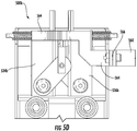
- a latching mechanism 670 includes a first body 672 and a second body 674, as described above.
- the latching mechanism 670 may be substantially similar to that described above and thus similar features and structures may be omitted for clarity and brevity.
- the first and second bodies 672, 674 each have respective latching elements 676, 678 extending therefrom, as described above.
- the first and second bodies 672, 674 are movably mounted on guide pins 680, 682.
- two guide pins 680, 682 are configured to aid in guiding the movement of the bodies 672, 674 relative to each other.
- the guide pins 680, 682 can be mounted to a housing (not shown) as described above.
- the bodies 672, 674 can be biased within the housing by one or more biasing members.
- the first guide pin 680 has a single biasing member 684 positioned between the first and second bodies 672, 674.
- the biasing member 684 can be configured to pull the two bodies 672, 674 toward each other.
- the second guide pin 682 has two biasing members 686, 688 positioned to the exterior of the bodies 672, 674 and would engage between the respective bodies 672, 674 and a portion or surface of the housing that houses the latching mechanism 670.
- the biasing member 684 is an extension spring and the biasing members 686, 688 are compression springs.
- the guide pins 680, 682 may integrally include a biasing feature.
- the latching mechanism 670 shown in FIG. 6 operates differently than that shown and described above.
- the bodies 672, 674 are urged by a wedge assembly 690.
- the wedge assembly 690 includes a movable wedge 692 that moves along inclined surfaces 694, 696 of the bodies 672, 674.
- the movable wedge 692 is actuated and moved similar to the link assembly described above. That is, an actuation arm that is attached to a handle can be moved or tilted to urge the movable wedge 692 downward, which will urge the two bodies 672, 674 apart, thus separating the latching elements 676, 678 to enable disengagement from a catch arm (as indicated by the dashed arrows in FIG. 6 ).
- various embodiments of the latch assemblies described herein are designed to overcome reliability issues associated with prior latch assembly configurations. Such improvement is achieved by means of improved and new mechanisms for locking and unlocking actions of the active latching elements of the latch assemblies.
- the latch assemblies described herein include latching elements, a latching mechanism to move the latching elements apart included for unlocking. Further, biasing mechanisms, such as spring, are provided for biasing and retracting the latching elements for locking and securing the latching elements with a catch or locking bracket.
- Guide pin(s) act as guides for transverse latching element movement, that is, the guide pin(s) provide a guide upon which bodies that support the latching elements move in a lateral or transverse direction.
- a handle moves an actuation arm which may push on a link connector that thus urges opposing links to move in opposite directions and thus separate the latching elements for unlocking.
- This action moves the bodies and latching elements apart along the guides and generates a sufficient gap or separation so as to disengage the latch from holding or locking bracket (e.g. a catch) and thus opening the closure (e.g., a door) to which the latch assembly is part of or attached to.
- the closure is pushed against the locking bracket.
- the profile on the front face of the catch will split or move the latching elements apart and the biasing mechanisms in the latch assembly will retract and the profile on the backside of the catch with which the latching elements are engaged will keep the closure in a locked position.
- various embodiments provided herein are direct to a synchronous multiple latch assembly.
- the multiple latch assembly system achieves synchronous movement of left and right latch assemblies under any condition which is the design intent and also can provide a cost benefit by avoidance of frequent replacement of system.
- the multiple latch system includes two latch assemblies (e.g., left and right) that are interconnected by means of an assembly connector.
- the left and right hand latch assemblies are formed similar to that described above.
- the latching elements will move apart and create a sufficient gap so as to disengage the latching elements from the locking bracket and thus enable opening of the closure to which the multiple latch assemblies are attached.
- synchronous movement of both latches The synchronous movement is provided with the connected latch assemblies.
- the assembly connector connects one of the latching element bodies in each latch assembly such that tandem or synchronous operation is achieved. That is, in some configurations, when a left hand handle of a left side latch assembly is moved rotationally upward, the left hand latching elements move apart which in turn moves the assembly connector. Such movement of the assembly connector will move the right hand latching element apart. Thus synchronous opening or closing of both latch assemblies can be achieved.
- the latching mechanism and biased elements can provide a more reliable and consistent operation for locking/unlocking action. Such improved reliability and consistency can improve latch assembly life. Further, advantageously, in the systems having multiple connected latch assemblies, only lateral or transilatory movement is required within the system to achieve locking/unlocking. Prior systems have transilatory motion that is converted to a rotary motion that is then, in turn, converted back to transilatory motion. Such changes in motion can lead to motion loss, slippage, stoppage, failure, etc. In contrast, embodiments of the present disclosure enable the use of only transilatory or lateral movement and thus no motion loss is experienced.
Landscapes
- Engineering & Computer Science (AREA)
- Mechanical Engineering (AREA)
- Structural Engineering (AREA)
- Casings For Electric Apparatus (AREA)
Claims (13)
- Ensemble verrou (200 ; 300 ; 400 ; 500a ; 500b) pour ouvrir et fermer une structure ouvrable, l'ensemble verrou (200 ; 300 ; 400 ; 500a ; 500b) comprenant :
un logement (204 ; 304) définissant une cavité (210), caractérisé par :une poignée (202 ; 302) montée de manière mobile sur le logement (204 ; 304) ; etun mécanisme de verrouillage (214 ; 314) dans la cavité (210) et disposé entre la poignée (202 ; 302) et le logement (204 ; 304), le mécanisme de verrouillage (214 ; 314) comprenant :
un premier corps (234 ; 334 ; 534a ; 534b) :le premier corps (234 ; 334 ; 534a ; 534b) ayant un premier élément de verrouillage (206 ; 306 ; 406) s'étendant à travers le logement (204 ; 304) ;un second corps (236 ; 336 ; 536a ; 536b) :le second corps (236 ; 336 ; 536a ; 536b) ayant un second élément de verrouillage (208 ; 308 ; 408) s'étendant à travers le logement (204 ; 304) ;une première liaison (240) fixée au premier corps (234 ; 334 ; 534a ; 534b) ;une seconde liaison (242) fixée au second corps (236 ; 336 ; 536a ; 536b) ; etun raccord de liaison (244 ; 344) reliant de manière fonctionnelle la première liaison (240) à la seconde liaison (242), dans lequel le déplacement du raccord de liaison (244 ; 344) pousse le premier élément de verrouillage (206 ; 306 ; 406) et le second élément de verrouillage (208 ; 308 ; 408) à distance à travers le déplacement de la première liaison (240) et de la seconde liaison (242) et du premier corps (234 ; 334 ; 534a ; 534b) et du second corps (236 ; 336 ; 536a ; 536b) ; caractériséen ce qu'au moins une tige de guidage (224 ; 324) est montée sur le logement (204 ; 304) ;dans lequel le premier corps (234 ; 334 ; 534a ; 534b) et le second corps (236 ; 336 ; 536a ; 536b) sont mobiles le long de l'au moins une tige de guidage (224 ; 324). - Ensemble verrou (200 ; 300 ; 400 ; 500a ; 500b) selon la revendication 1, comprenant en outre un bras d'actionnement (226 ; 326) relié de manière fixe à la poignée (202 ; 302) de sorte que le déplacement de la poignée (202 ; 302) entraîne le déplacement du raccord de liaison (244 ; 344).
- Ensemble verrou (200 ; 300 ; 400 ; 500a ; 500b) selon la revendication 2, comprenant en outre un couvercle (212) installé entre la poignée (202 ; 302) et le mécanisme de verrouillage (214 ; 314) à l'intérieur de la cavité (210), le couvercle (212) étant conçu pour couvrir le premier corps (234 ; 334 ; 534a ; 534b) et le second corps (236 ; 336 ; 536a ; 536b), de préférence dans lequel le couvercle (212) comporte au moins l'une d'au moins une structure de guidage de couvercle (230), la structure de guidage de couvercle (230) étant conçue pour guider le déplacement du raccord de liaison (244 ; 344), et une fente d'actionnement (228) où le bras d'actionnement (226 ; 326) passe à travers le couvercle (212) pour interagir avec le raccord de liaison (244 ; 344).
- Ensemble verrou (200 ; 300 ; 400 ; 500a ; 500b) selon l'une quelconque des revendications 2 et 3, dans lequel le logement (204 ; 304) comporte au moins une structure de guidage de logement (232), la structure de guidage de logement (232) étant conçue pour guider le déplacement du raccord de liaison (244 ; 344) .
- Ensemble verrou (200 ; 300 ; 400 ; 500a ; 500b) selon une quelconque revendication précédente, comprenant en outre au moins un élément de sollicitation (246 ; 248 ; 346 ; 348) disposé sur l'au moins une tige de guidage (224 ; 324) et conçu pour pousser le premier corps vers le second corps (236 ; 336 ; 536a ; 536b) le long de l'au moins une tige de guidage (224 ; 324), de préférence, dans lequel l'au moins un élément de sollicitation (246 ; 248 ; 346 ; 348) comprend un premier élément de sollicitation (246 ; 346) disposé entre le premier corps (234 ; 334 ; 534a ; 534b) et le logement (204 ; 304) et un second élément de sollicitation (248 ; 348) disposé entre le second corps (236 ; 336 ; 536a ; 536b) et le logement (204 ; 304) .
- Ensemble verrou (200 ; 300 ; 400 ; 500a ; 500b) selon une quelconque revendication précédente, comprenant en outre un support de verrouillage (350; 450) conçu pour recevoir le premier élément de verrouillage et le second élément de verrouillage afin de fixer les éléments de verrouillage dans un premier état.
- Ensemble verrou (200 ; 300 ; 400 ; 500a ; 500b) selon la revendication 6, dans lequel le support de verrouillage (350 ; 450) comporte un bras d'accrochage (452), le bras d'accrochage (452) ayant au moins une surface de butée conçue pour recevoir le premier élément de verrouillage (206 ; 306 ; 406) et le second élément de verrouillage (208 ; 308 ; 408) afin de fixer les premier (206 ; 306 ; 406) et second (208 ; 308 ; 408) éléments de verrouillage dans le premier état.
- Ensemble verrou (200 ; 300 ; 400 ; 500a ; 500b) selon la revendication 7, le bras d'accrochage (452) comprenant en outre une surface d'expansion conçue pour étendre le premier élément de verrouillage à distance du second élément de verrouillage lorsque l'ensemble verrou (200 ; 300 ; 400 ; 500a ; 500b) est déplacé dans le premier état.
- Ensemble verrou (200 ; 300 ; 400 ; 500a ; 500b) selon la revendication 8, dans lequel chacun du premier élément de verrouillage (206 ; 306 ; 406) et du second élément de verrouillage (208 ; 308 ; 408) comprennent une surface de mise en prise complémentaire qui vient en prise avec la surface d'expansion du bras d'accrochage (452) et se trouve le long de celle-ci.
- Ensemble verrou (200 ; 300 ; 400 ; 500a ; 500b) selon la revendication 7, dans lequel une partie du bras d'accrochage (452) a une largeur (W) et, dans le premier état, les premier (206 ; 306 ; 406) et second (208 ; 308 ; 408) éléments de verrouillage sont séparés par une première distance de séparation (D1) qui est inférieure à la largeur (W) du bras d'accrochage (452) et, dans un second état, les premier (206 ; 306 ; 406) et second (208 ; 308 ; 408) éléments de verrouillage sont séparés par une seconde distance de séparation (D2) qui est supérieure à la largeur (W) du bras d'accrochage (452) de sorte que les premier (206 ; 306 ; 406) et second (208 ; 308 ; 408) éléments de verrouillage peuvent se déplacer librement par rapport au bras d'accrochage (452).
- Ensemble verrou pour ouvrir et fermer une structure ouvrable, l'ensemble verrou comprenant :
un logement définissant une cavité, caractérisé par :une poignée montée de manière mobile sur le logement ; etun mécanisme de verrouillage (670) dans la cavité et disposé entre la poignée et le logement, le mécanisme de verrouillage (670) comprenant :un premier corps (672), le premier corps (672) ayant un premier élément de verrouillage (676) s'étendant à travers le logement et ayant une surface inclinée ;un second corps (674), le second corps (674) ayant un second élément de verrouillage (678) s'étendant à travers le logement et ayant une surface inclinée ; caractérisé en ce qu'au moins une tige de guidage (224 ; 324) est montée sur le logement (204 ; 304) ; dans lequel le premier corps (234 ; 334 ; 534a ; 534b) et le second corps (236 ; 336 ; 536a ; 536b) sont mobiles le long de l'au moins une tige de guidage (224 ; 324) ;une cale mobile (692) positionnée entre les surfaces inclinées du premier corps (672) et du second corps (674) ; etun bras d'actionnement relié de manière fixe à la poignée de sorte que le déplacement de la poignée entraîne le déplacement de la cale mobile (692), dans lequel le déplacement de la cale mobile (692) pousse le premier élément de verrouillage (676) et le second élément de verrouillage à distance à travers le déplacement du premier corps (672) et du second corps (674) étendus par la cale mobile (692) le long des surfaces inclinées. - Structure ouvrable comprenant :un cadre ;un corps de fermeture mobile par rapport au cadre ; etun premier ensemble verrou (200 ; 300 ; 400 ; 500a ; 500b) au moins partiellement installé sur le corps de fermeture, le premier ensemble verrou (200 ; 300 ; 400 ; 500a ; 500b) étant un ensemble verrou (200 ; 300; 400 ; 500a) selon l'une quelconque des revendications 1 à 11.
- Structure ouvrable selon la revendication 12, comprenant en outre un second ensemble verrou (200 ; 300 ; 400 ; 500b), dans lequel les premier et second ensembles verrou (200 ; 300 ; 400 ; 500a ; 500b) sont reliés de manière opérationnelle pour fonctionner de manière synchrone lors du fonctionnement de l'un des premier ou second ensembles verrou.
Applications Claiming Priority (1)
| Application Number | Priority Date | Filing Date | Title |
|---|---|---|---|
| IN201611042838 | 2016-12-15 |
Publications (2)
| Publication Number | Publication Date |
|---|---|
| EP3336285A1 EP3336285A1 (fr) | 2018-06-20 |
| EP3336285B1 true EP3336285B1 (fr) | 2021-03-10 |
Family
ID=60673192
Family Applications (1)
| Application Number | Title | Priority Date | Filing Date |
|---|---|---|---|
| EP17206762.1A Active EP3336285B1 (fr) | 2016-12-15 | 2017-12-12 | Ensembles verrou de fermeture |
Country Status (2)
| Country | Link |
|---|---|
| US (1) | US10557293B2 (fr) |
| EP (1) | EP3336285B1 (fr) |
Families Citing this family (6)
| Publication number | Priority date | Publication date | Assignee | Title |
|---|---|---|---|---|
| US10557293B2 (en) * | 2016-12-15 | 2020-02-11 | Ami Industries, Inc. | Closure latch assemblies |
| US10550614B2 (en) * | 2016-12-15 | 2020-02-04 | Ami Industries, Inc. | Dual latch assembly for openable structures |
| CN110130743B (zh) * | 2019-06-17 | 2024-06-21 | 北京呈创科技股份有限公司 | 一种具有接电功能的锁具 |
| USD981819S1 (en) * | 2020-10-30 | 2023-03-28 | Zoox, Inc. | Vehicle with a door opening lever |
| USD1085115S1 (en) | 2023-06-19 | 2025-07-22 | Zoox, Inc. | Display screen or portion thereof with a graphical user interface |
| EP4571022A1 (fr) * | 2023-12-14 | 2025-06-18 | B/E Aerospace (UK) Limited | Mécanisme de verrouillage |
Family Cites Families (17)
| Publication number | Priority date | Publication date | Assignee | Title |
|---|---|---|---|---|
| US3026131A (en) * | 1958-11-19 | 1962-03-20 | Chicago Forging & Mfg Co | Self adjusting dual latch |
| US3743336A (en) | 1972-07-03 | 1973-07-03 | Sealth Aero Marine | Frictionless cabinet latch |
| US3857594A (en) | 1972-08-30 | 1974-12-31 | Eastern Co | Door lock assembly |
| GB9322299D0 (en) | 1993-10-29 | 1993-12-15 | Vega Ltd | A lock mechanism |
| US6023953A (en) | 1998-01-30 | 2000-02-15 | Southco, Inc. | Slam latch with opposing slides |
| US6079585A (en) * | 1998-09-14 | 2000-06-27 | Lentini; Robert | Truck box with improved operating rod |
| US6349577B1 (en) * | 1999-10-26 | 2002-02-26 | Randall C. Hansen | Truck box paddle handle assembly with rotatable release mechanism |
| US6454320B1 (en) * | 1999-10-28 | 2002-09-24 | The Eastern Company | Push button operators for latches and locks and locking systems employing lockable push button operators |
| US6386409B1 (en) * | 1999-12-16 | 2002-05-14 | Dale S. Cheney | Vehicle storage box with single hinged double secured compartments and dual actuating cam latches |
| US6502868B1 (en) * | 2000-09-01 | 2003-01-07 | Protech Industries, Inc. | Dual T-lock apparatus |
| US6857298B2 (en) * | 2002-12-27 | 2005-02-22 | S.P.E.P. Acquisition Corporation | Double action push button locking system |
| US7497103B1 (en) | 2006-04-22 | 2009-03-03 | The Eastern Company | Dual-acting latch and strike |
| US9151078B2 (en) * | 2013-08-15 | 2015-10-06 | Daws Manufacturing Co., Inc. | Truck box with keyless entry system |
| US9260890B2 (en) * | 2014-05-13 | 2016-02-16 | Daws Manufacturing Co., Inc. | Latch mechanism |
| US10272003B2 (en) * | 2016-08-08 | 2019-04-30 | The Braun Corporation | Rear entry latch assembly |
| US10550614B2 (en) * | 2016-12-15 | 2020-02-04 | Ami Industries, Inc. | Dual latch assembly for openable structures |
| US10557293B2 (en) * | 2016-12-15 | 2020-02-11 | Ami Industries, Inc. | Closure latch assemblies |
-
2017
- 2017-02-07 US US15/426,103 patent/US10557293B2/en active Active
- 2017-12-12 EP EP17206762.1A patent/EP3336285B1/fr active Active
Non-Patent Citations (1)
| Title |
|---|
| None * |
Also Published As
| Publication number | Publication date |
|---|---|
| US10557293B2 (en) | 2020-02-11 |
| EP3336285A1 (fr) | 2018-06-20 |
| US20180171687A1 (en) | 2018-06-21 |
Similar Documents
| Publication | Publication Date | Title |
|---|---|---|
| EP3336285B1 (fr) | Ensembles verrou de fermeture | |
| EP3336291B1 (fr) | Ensemble à double verrouillage pour structures ouvrables | |
| US8083269B2 (en) | Apparatus for effecting an initial, predetermined translation of a closed sliding door | |
| US11959307B2 (en) | Lever action automatic shootbolt operator with magnetically-triggered locking mechanism | |
| EP3423652B1 (fr) | Agencement de verrou ayant une poignée | |
| AU2008279898B2 (en) | A latch | |
| IL259503A (en) | Another closed door or panel with a lock-operated link | |
| US7950703B2 (en) | Door latch mechanism | |
| KR101982007B1 (ko) | 개선된 구조의 래치유닛을 갖는 실내 도어용 푸쉬풀 도어락 | |
| CA2487200C (fr) | Systeme de porte de mine a mecanisme de verrouillage par declenchement | |
| KR101467285B1 (ko) | 래치볼트의 고정구조체 | |
| US20140265371A1 (en) | Handle Assembly | |
| US20240392607A1 (en) | Push Pad Exit Device for Emergency Door Egress and Vertical Latch Bolt Assembly | |
| US12291892B2 (en) | Panel closure apparatus | |
| GB2423787A (en) | Bi-directional bolt-restraint mechanism | |
| US12163356B2 (en) | Lever action automatic shootbolt operator with magnetically-triggered lock mechanism | |
| EP1662075B1 (fr) | Poignée anti-panique | |
| GB2536224A (en) | Lock | |
| CN117280107B (zh) | 机动车锁 | |
| CA2954216C (fr) | Ensemble de poignee de porte moustiquaire retractable | |
| CA2629730C (fr) | Appareil pour une translation initiale predeterminee de porte coulissante verrouillee | |
| KR100999175B1 (ko) | 창호용 록킹장치 | |
| WO2023154054A1 (fr) | Actionneur de pêne coulissant automatique à action de levier comprenant un mécanisme de verrouillage à déclenchement magnétique | |
| CN203846888U (zh) | 气密隔音门锁 |
Legal Events
| Date | Code | Title | Description |
|---|---|---|---|
| PUAI | Public reference made under article 153(3) epc to a published international application that has entered the european phase |
Free format text: ORIGINAL CODE: 0009012 |
|
| STAA | Information on the status of an ep patent application or granted ep patent |
Free format text: STATUS: THE APPLICATION HAS BEEN PUBLISHED |
|
| AK | Designated contracting states |
Kind code of ref document: A1 Designated state(s): AL AT BE BG CH CY CZ DE DK EE ES FI FR GB GR HR HU IE IS IT LI LT LU LV MC MK MT NL NO PL PT RO RS SE SI SK SM TR |
|
| AX | Request for extension of the european patent |
Extension state: BA ME |
|
| STAA | Information on the status of an ep patent application or granted ep patent |
Free format text: STATUS: REQUEST FOR EXAMINATION WAS MADE |
|
| 17P | Request for examination filed |
Effective date: 20181219 |
|
| RBV | Designated contracting states (corrected) |
Designated state(s): AL AT BE BG CH CY CZ DE DK EE ES FI FR GB GR HR HU IE IS IT LI LT LU LV MC MK MT NL NO PL PT RO RS SE SI SK SM TR |
|
| RIC1 | Information provided on ipc code assigned before grant |
Ipc: E05B 5/00 20060101ALI20200903BHEP Ipc: E05B 63/14 20060101AFI20200903BHEP Ipc: E05B 15/02 20060101ALN20200903BHEP Ipc: E05B 15/04 20060101ALN20200903BHEP Ipc: E05C 1/14 20060101ALI20200903BHEP |
|
| GRAP | Despatch of communication of intention to grant a patent |
Free format text: ORIGINAL CODE: EPIDOSNIGR1 |
|
| STAA | Information on the status of an ep patent application or granted ep patent |
Free format text: STATUS: GRANT OF PATENT IS INTENDED |
|
| RIC1 | Information provided on ipc code assigned before grant |
Ipc: E05C 1/14 20060101ALI20200904BHEP Ipc: E05B 15/04 20060101ALN20200904BHEP Ipc: E05B 5/00 20060101ALI20200904BHEP Ipc: E05B 15/02 20060101ALN20200904BHEP Ipc: E05B 63/14 20060101AFI20200904BHEP |
|
| INTG | Intention to grant announced |
Effective date: 20201012 |
|
| GRAS | Grant fee paid |
Free format text: ORIGINAL CODE: EPIDOSNIGR3 |
|
| GRAA | (expected) grant |
Free format text: ORIGINAL CODE: 0009210 |
|
| STAA | Information on the status of an ep patent application or granted ep patent |
Free format text: STATUS: THE PATENT HAS BEEN GRANTED |
|
| AK | Designated contracting states |
Kind code of ref document: B1 Designated state(s): AL AT BE BG CH CY CZ DE DK EE ES FI FR GB GR HR HU IE IS IT LI LT LU LV MC MK MT NL NO PL PT RO RS SE SI SK SM TR |
|
| REG | Reference to a national code |
Ref country code: GB Ref legal event code: FG4D |
|
| REG | Reference to a national code |
Ref country code: AT Ref legal event code: REF Ref document number: 1369965 Country of ref document: AT Kind code of ref document: T Effective date: 20210315 Ref country code: CH Ref legal event code: EP |
|
| REG | Reference to a national code |
Ref country code: IE Ref legal event code: FG4D |
|
| REG | Reference to a national code |
Ref country code: DE Ref legal event code: R096 Ref document number: 602017034235 Country of ref document: DE |
|
| REG | Reference to a national code |
Ref country code: LT Ref legal event code: MG9D |
|
| PG25 | Lapsed in a contracting state [announced via postgrant information from national office to epo] |
Ref country code: HR Free format text: LAPSE BECAUSE OF FAILURE TO SUBMIT A TRANSLATION OF THE DESCRIPTION OR TO PAY THE FEE WITHIN THE PRESCRIBED TIME-LIMIT Effective date: 20210310 Ref country code: GR Free format text: LAPSE BECAUSE OF FAILURE TO SUBMIT A TRANSLATION OF THE DESCRIPTION OR TO PAY THE FEE WITHIN THE PRESCRIBED TIME-LIMIT Effective date: 20210611 Ref country code: FI Free format text: LAPSE BECAUSE OF FAILURE TO SUBMIT A TRANSLATION OF THE DESCRIPTION OR TO PAY THE FEE WITHIN THE PRESCRIBED TIME-LIMIT Effective date: 20210310 Ref country code: NO Free format text: LAPSE BECAUSE OF FAILURE TO SUBMIT A TRANSLATION OF THE DESCRIPTION OR TO PAY THE FEE WITHIN THE PRESCRIBED TIME-LIMIT Effective date: 20210610 Ref country code: BG Free format text: LAPSE BECAUSE OF FAILURE TO SUBMIT A TRANSLATION OF THE DESCRIPTION OR TO PAY THE FEE WITHIN THE PRESCRIBED TIME-LIMIT Effective date: 20210610 Ref country code: LT Free format text: LAPSE BECAUSE OF FAILURE TO SUBMIT A TRANSLATION OF THE DESCRIPTION OR TO PAY THE FEE WITHIN THE PRESCRIBED TIME-LIMIT Effective date: 20210310 |
|
| REG | Reference to a national code |
Ref country code: AT Ref legal event code: MK05 Ref document number: 1369965 Country of ref document: AT Kind code of ref document: T Effective date: 20210310 |
|
| REG | Reference to a national code |
Ref country code: NL Ref legal event code: MP Effective date: 20210310 |
|
| PG25 | Lapsed in a contracting state [announced via postgrant information from national office to epo] |
Ref country code: SE Free format text: LAPSE BECAUSE OF FAILURE TO SUBMIT A TRANSLATION OF THE DESCRIPTION OR TO PAY THE FEE WITHIN THE PRESCRIBED TIME-LIMIT Effective date: 20210310 Ref country code: RS Free format text: LAPSE BECAUSE OF FAILURE TO SUBMIT A TRANSLATION OF THE DESCRIPTION OR TO PAY THE FEE WITHIN THE PRESCRIBED TIME-LIMIT Effective date: 20210310 Ref country code: LV Free format text: LAPSE BECAUSE OF FAILURE TO SUBMIT A TRANSLATION OF THE DESCRIPTION OR TO PAY THE FEE WITHIN THE PRESCRIBED TIME-LIMIT Effective date: 20210310 |
|
| PG25 | Lapsed in a contracting state [announced via postgrant information from national office to epo] |
Ref country code: NL Free format text: LAPSE BECAUSE OF FAILURE TO SUBMIT A TRANSLATION OF THE DESCRIPTION OR TO PAY THE FEE WITHIN THE PRESCRIBED TIME-LIMIT Effective date: 20210310 |
|
| PG25 | Lapsed in a contracting state [announced via postgrant information from national office to epo] |
Ref country code: CZ Free format text: LAPSE BECAUSE OF FAILURE TO SUBMIT A TRANSLATION OF THE DESCRIPTION OR TO PAY THE FEE WITHIN THE PRESCRIBED TIME-LIMIT Effective date: 20210310 Ref country code: EE Free format text: LAPSE BECAUSE OF FAILURE TO SUBMIT A TRANSLATION OF THE DESCRIPTION OR TO PAY THE FEE WITHIN THE PRESCRIBED TIME-LIMIT Effective date: 20210310 Ref country code: SM Free format text: LAPSE BECAUSE OF FAILURE TO SUBMIT A TRANSLATION OF THE DESCRIPTION OR TO PAY THE FEE WITHIN THE PRESCRIBED TIME-LIMIT Effective date: 20210310 Ref country code: AT Free format text: LAPSE BECAUSE OF FAILURE TO SUBMIT A TRANSLATION OF THE DESCRIPTION OR TO PAY THE FEE WITHIN THE PRESCRIBED TIME-LIMIT Effective date: 20210310 |
|
| PG25 | Lapsed in a contracting state [announced via postgrant information from national office to epo] |
Ref country code: RO Free format text: LAPSE BECAUSE OF FAILURE TO SUBMIT A TRANSLATION OF THE DESCRIPTION OR TO PAY THE FEE WITHIN THE PRESCRIBED TIME-LIMIT Effective date: 20210310 Ref country code: SK Free format text: LAPSE BECAUSE OF FAILURE TO SUBMIT A TRANSLATION OF THE DESCRIPTION OR TO PAY THE FEE WITHIN THE PRESCRIBED TIME-LIMIT Effective date: 20210310 Ref country code: PL Free format text: LAPSE BECAUSE OF FAILURE TO SUBMIT A TRANSLATION OF THE DESCRIPTION OR TO PAY THE FEE WITHIN THE PRESCRIBED TIME-LIMIT Effective date: 20210310 Ref country code: PT Free format text: LAPSE BECAUSE OF FAILURE TO SUBMIT A TRANSLATION OF THE DESCRIPTION OR TO PAY THE FEE WITHIN THE PRESCRIBED TIME-LIMIT Effective date: 20210712 Ref country code: IS Free format text: LAPSE BECAUSE OF FAILURE TO SUBMIT A TRANSLATION OF THE DESCRIPTION OR TO PAY THE FEE WITHIN THE PRESCRIBED TIME-LIMIT Effective date: 20210710 |
|
| REG | Reference to a national code |
Ref country code: DE Ref legal event code: R097 Ref document number: 602017034235 Country of ref document: DE |
|
| PLBE | No opposition filed within time limit |
Free format text: ORIGINAL CODE: 0009261 |
|
| STAA | Information on the status of an ep patent application or granted ep patent |
Free format text: STATUS: NO OPPOSITION FILED WITHIN TIME LIMIT |
|
| PG25 | Lapsed in a contracting state [announced via postgrant information from national office to epo] |
Ref country code: ES Free format text: LAPSE BECAUSE OF FAILURE TO SUBMIT A TRANSLATION OF THE DESCRIPTION OR TO PAY THE FEE WITHIN THE PRESCRIBED TIME-LIMIT Effective date: 20210310 Ref country code: AL Free format text: LAPSE BECAUSE OF FAILURE TO SUBMIT A TRANSLATION OF THE DESCRIPTION OR TO PAY THE FEE WITHIN THE PRESCRIBED TIME-LIMIT Effective date: 20210310 Ref country code: DK Free format text: LAPSE BECAUSE OF FAILURE TO SUBMIT A TRANSLATION OF THE DESCRIPTION OR TO PAY THE FEE WITHIN THE PRESCRIBED TIME-LIMIT Effective date: 20210310 |
|
| 26N | No opposition filed |
Effective date: 20211213 |
|
| PG25 | Lapsed in a contracting state [announced via postgrant information from national office to epo] |
Ref country code: SI Free format text: LAPSE BECAUSE OF FAILURE TO SUBMIT A TRANSLATION OF THE DESCRIPTION OR TO PAY THE FEE WITHIN THE PRESCRIBED TIME-LIMIT Effective date: 20210310 |
|
| PG25 | Lapsed in a contracting state [announced via postgrant information from national office to epo] |
Ref country code: IT Free format text: LAPSE BECAUSE OF FAILURE TO SUBMIT A TRANSLATION OF THE DESCRIPTION OR TO PAY THE FEE WITHIN THE PRESCRIBED TIME-LIMIT Effective date: 20210310 |
|
| PG25 | Lapsed in a contracting state [announced via postgrant information from national office to epo] |
Ref country code: IS Free format text: LAPSE BECAUSE OF FAILURE TO SUBMIT A TRANSLATION OF THE DESCRIPTION OR TO PAY THE FEE WITHIN THE PRESCRIBED TIME-LIMIT Effective date: 20210710 |
|
| PG25 | Lapsed in a contracting state [announced via postgrant information from national office to epo] |
Ref country code: MC Free format text: LAPSE BECAUSE OF FAILURE TO SUBMIT A TRANSLATION OF THE DESCRIPTION OR TO PAY THE FEE WITHIN THE PRESCRIBED TIME-LIMIT Effective date: 20210310 |
|
| REG | Reference to a national code |
Ref country code: CH Ref legal event code: PL |
|
| REG | Reference to a national code |
Ref country code: BE Ref legal event code: MM Effective date: 20211231 |
|
| PG25 | Lapsed in a contracting state [announced via postgrant information from national office to epo] |
Ref country code: LU Free format text: LAPSE BECAUSE OF NON-PAYMENT OF DUE FEES Effective date: 20211212 Ref country code: IE Free format text: LAPSE BECAUSE OF NON-PAYMENT OF DUE FEES Effective date: 20211212 |
|
| PG25 | Lapsed in a contracting state [announced via postgrant information from national office to epo] |
Ref country code: BE Free format text: LAPSE BECAUSE OF NON-PAYMENT OF DUE FEES Effective date: 20211231 |
|
| PG25 | Lapsed in a contracting state [announced via postgrant information from national office to epo] |
Ref country code: LI Free format text: LAPSE BECAUSE OF NON-PAYMENT OF DUE FEES Effective date: 20211231 Ref country code: CH Free format text: LAPSE BECAUSE OF NON-PAYMENT OF DUE FEES Effective date: 20211231 |
|
| PG25 | Lapsed in a contracting state [announced via postgrant information from national office to epo] |
Ref country code: HU Free format text: LAPSE BECAUSE OF FAILURE TO SUBMIT A TRANSLATION OF THE DESCRIPTION OR TO PAY THE FEE WITHIN THE PRESCRIBED TIME-LIMIT; INVALID AB INITIO Effective date: 20171212 |
|
| P01 | Opt-out of the competence of the unified patent court (upc) registered |
Effective date: 20230521 |
|
| PG25 | Lapsed in a contracting state [announced via postgrant information from national office to epo] |
Ref country code: CY Free format text: LAPSE BECAUSE OF FAILURE TO SUBMIT A TRANSLATION OF THE DESCRIPTION OR TO PAY THE FEE WITHIN THE PRESCRIBED TIME-LIMIT Effective date: 20210310 |
|
| PG25 | Lapsed in a contracting state [announced via postgrant information from national office to epo] |
Ref country code: MK Free format text: LAPSE BECAUSE OF FAILURE TO SUBMIT A TRANSLATION OF THE DESCRIPTION OR TO PAY THE FEE WITHIN THE PRESCRIBED TIME-LIMIT Effective date: 20210310 |
|
| PG25 | Lapsed in a contracting state [announced via postgrant information from national office to epo] |
Ref country code: MT Free format text: LAPSE BECAUSE OF FAILURE TO SUBMIT A TRANSLATION OF THE DESCRIPTION OR TO PAY THE FEE WITHIN THE PRESCRIBED TIME-LIMIT Effective date: 20210310 |
|
| PG25 | Lapsed in a contracting state [announced via postgrant information from national office to epo] |
Ref country code: TR Free format text: LAPSE BECAUSE OF FAILURE TO SUBMIT A TRANSLATION OF THE DESCRIPTION OR TO PAY THE FEE WITHIN THE PRESCRIBED TIME-LIMIT Effective date: 20210310 |
|
| PGFP | Annual fee paid to national office [announced via postgrant information from national office to epo] |
Ref country code: DE Payment date: 20251126 Year of fee payment: 9 |
|
| PGFP | Annual fee paid to national office [announced via postgrant information from national office to epo] |
Ref country code: GB Payment date: 20251120 Year of fee payment: 9 |
|
| PGFP | Annual fee paid to national office [announced via postgrant information from national office to epo] |
Ref country code: FR Payment date: 20251120 Year of fee payment: 9 |