EP3336337B1 - Verfahren zum betreiben eines verbrennungsmotors mit gasförmigem brennstoff - Google Patents
Verfahren zum betreiben eines verbrennungsmotors mit gasförmigem brennstoff Download PDFInfo
- Publication number
- EP3336337B1 EP3336337B1 EP16204329.3A EP16204329A EP3336337B1 EP 3336337 B1 EP3336337 B1 EP 3336337B1 EP 16204329 A EP16204329 A EP 16204329A EP 3336337 B1 EP3336337 B1 EP 3336337B1
- Authority
- EP
- European Patent Office
- Prior art keywords
- combustion
- liquid fuel
- fuel
- parameter
- cylinder
- Prior art date
- Legal status (The legal status is an assumption and is not a legal conclusion. Google has not performed a legal analysis and makes no representation as to the accuracy of the status listed.)
- Active
Links
Images

Classifications
-
- F—MECHANICAL ENGINEERING; LIGHTING; HEATING; WEAPONS; BLASTING
- F02—COMBUSTION ENGINES; HOT-GAS OR COMBUSTION-PRODUCT ENGINE PLANTS
- F02D—CONTROLLING COMBUSTION ENGINES
- F02D41/00—Electrical control of supply of combustible mixture or its constituents
- F02D41/30—Controlling fuel injection
- F02D41/3011—Controlling fuel injection according to or using specific or several modes of combustion
- F02D41/3017—Controlling fuel injection according to or using specific or several modes of combustion characterised by the mode(s) being used
- F02D41/3035—Controlling fuel injection according to or using specific or several modes of combustion characterised by the mode(s) being used a mode being the premixed charge compression-ignition mode
- F02D41/3041—Controlling fuel injection according to or using specific or several modes of combustion characterised by the mode(s) being used a mode being the premixed charge compression-ignition mode with means for triggering compression ignition, e.g. spark plug
- F02D41/3047—Controlling fuel injection according to or using specific or several modes of combustion characterised by the mode(s) being used a mode being the premixed charge compression-ignition mode with means for triggering compression ignition, e.g. spark plug said means being a secondary injection of fuel
-
- F—MECHANICAL ENGINEERING; LIGHTING; HEATING; WEAPONS; BLASTING
- F02—COMBUSTION ENGINES; HOT-GAS OR COMBUSTION-PRODUCT ENGINE PLANTS
- F02D—CONTROLLING COMBUSTION ENGINES
- F02D19/00—Controlling engines characterised by their use of non-liquid fuels, pluralities of fuels, or non-fuel substances added to the combustible mixtures
- F02D19/06—Controlling engines characterised by their use of non-liquid fuels, pluralities of fuels, or non-fuel substances added to the combustible mixtures peculiar to engines working with pluralities of fuels, e.g. alternatively with light and heavy fuel oil, other than engines indifferent to the fuel consumed
- F02D19/0602—Control of components of the fuel supply system
- F02D19/0607—Control of components of the fuel supply system to adjust the fuel mass or volume flow
- F02D19/061—Control of components of the fuel supply system to adjust the fuel mass or volume flow by controlling fuel injectors
-
- F—MECHANICAL ENGINEERING; LIGHTING; HEATING; WEAPONS; BLASTING
- F02—COMBUSTION ENGINES; HOT-GAS OR COMBUSTION-PRODUCT ENGINE PLANTS
- F02D—CONTROLLING COMBUSTION ENGINES
- F02D19/00—Controlling engines characterised by their use of non-liquid fuels, pluralities of fuels, or non-fuel substances added to the combustible mixtures
- F02D19/06—Controlling engines characterised by their use of non-liquid fuels, pluralities of fuels, or non-fuel substances added to the combustible mixtures peculiar to engines working with pluralities of fuels, e.g. alternatively with light and heavy fuel oil, other than engines indifferent to the fuel consumed
- F02D19/0639—Controlling engines characterised by their use of non-liquid fuels, pluralities of fuels, or non-fuel substances added to the combustible mixtures peculiar to engines working with pluralities of fuels, e.g. alternatively with light and heavy fuel oil, other than engines indifferent to the fuel consumed characterised by the type of fuels
- F02D19/0642—Controlling engines characterised by their use of non-liquid fuels, pluralities of fuels, or non-fuel substances added to the combustible mixtures peculiar to engines working with pluralities of fuels, e.g. alternatively with light and heavy fuel oil, other than engines indifferent to the fuel consumed characterised by the type of fuels at least one fuel being gaseous, the other fuels being gaseous or liquid at standard conditions
-
- F—MECHANICAL ENGINEERING; LIGHTING; HEATING; WEAPONS; BLASTING
- F02—COMBUSTION ENGINES; HOT-GAS OR COMBUSTION-PRODUCT ENGINE PLANTS
- F02D—CONTROLLING COMBUSTION ENGINES
- F02D19/00—Controlling engines characterised by their use of non-liquid fuels, pluralities of fuels, or non-fuel substances added to the combustible mixtures
- F02D19/06—Controlling engines characterised by their use of non-liquid fuels, pluralities of fuels, or non-fuel substances added to the combustible mixtures peculiar to engines working with pluralities of fuels, e.g. alternatively with light and heavy fuel oil, other than engines indifferent to the fuel consumed
- F02D19/08—Controlling engines characterised by their use of non-liquid fuels, pluralities of fuels, or non-fuel substances added to the combustible mixtures peculiar to engines working with pluralities of fuels, e.g. alternatively with light and heavy fuel oil, other than engines indifferent to the fuel consumed simultaneously using pluralities of fuels
- F02D19/10—Controlling engines characterised by their use of non-liquid fuels, pluralities of fuels, or non-fuel substances added to the combustible mixtures peculiar to engines working with pluralities of fuels, e.g. alternatively with light and heavy fuel oil, other than engines indifferent to the fuel consumed simultaneously using pluralities of fuels peculiar to compression-ignition engines in which the main fuel is gaseous
-
- F—MECHANICAL ENGINEERING; LIGHTING; HEATING; WEAPONS; BLASTING
- F02—COMBUSTION ENGINES; HOT-GAS OR COMBUSTION-PRODUCT ENGINE PLANTS
- F02D—CONTROLLING COMBUSTION ENGINES
- F02D35/00—Controlling engines, dependent on conditions exterior or interior to engines, not otherwise provided for
- F02D35/0015—Controlling engines, dependent on conditions exterior or interior to engines, not otherwise provided for using exhaust gas sensors
- F02D35/0046—Controlling fuel supply
- F02D35/0092—Controlling fuel supply by means of fuel injection
-
- F—MECHANICAL ENGINEERING; LIGHTING; HEATING; WEAPONS; BLASTING
- F02—COMBUSTION ENGINES; HOT-GAS OR COMBUSTION-PRODUCT ENGINE PLANTS
- F02D—CONTROLLING COMBUSTION ENGINES
- F02D35/00—Controlling engines, dependent on conditions exterior or interior to engines, not otherwise provided for
- F02D35/02—Controlling engines, dependent on conditions exterior or interior to engines, not otherwise provided for on interior conditions
- F02D35/023—Controlling engines, dependent on conditions exterior or interior to engines, not otherwise provided for on interior conditions by determining the cylinder pressure
-
- F—MECHANICAL ENGINEERING; LIGHTING; HEATING; WEAPONS; BLASTING
- F02—COMBUSTION ENGINES; HOT-GAS OR COMBUSTION-PRODUCT ENGINE PLANTS
- F02D—CONTROLLING COMBUSTION ENGINES
- F02D35/00—Controlling engines, dependent on conditions exterior or interior to engines, not otherwise provided for
- F02D35/02—Controlling engines, dependent on conditions exterior or interior to engines, not otherwise provided for on interior conditions
- F02D35/028—Controlling engines, dependent on conditions exterior or interior to engines, not otherwise provided for on interior conditions by determining the combustion timing or phasing
-
- F—MECHANICAL ENGINEERING; LIGHTING; HEATING; WEAPONS; BLASTING
- F02—COMBUSTION ENGINES; HOT-GAS OR COMBUSTION-PRODUCT ENGINE PLANTS
- F02D—CONTROLLING COMBUSTION ENGINES
- F02D41/00—Electrical control of supply of combustible mixture or its constituents
- F02D41/0025—Controlling engines characterised by use of non-liquid fuels, pluralities of fuels, or non-fuel substances added to the combustible mixtures
-
- F—MECHANICAL ENGINEERING; LIGHTING; HEATING; WEAPONS; BLASTING
- F02—COMBUSTION ENGINES; HOT-GAS OR COMBUSTION-PRODUCT ENGINE PLANTS
- F02D—CONTROLLING COMBUSTION ENGINES
- F02D41/00—Electrical control of supply of combustible mixture or its constituents
- F02D41/0025—Controlling engines characterised by use of non-liquid fuels, pluralities of fuels, or non-fuel substances added to the combustible mixtures
- F02D41/0027—Controlling engines characterised by use of non-liquid fuels, pluralities of fuels, or non-fuel substances added to the combustible mixtures the fuel being gaseous
-
- F—MECHANICAL ENGINEERING; LIGHTING; HEATING; WEAPONS; BLASTING
- F02—COMBUSTION ENGINES; HOT-GAS OR COMBUSTION-PRODUCT ENGINE PLANTS
- F02D—CONTROLLING COMBUSTION ENGINES
- F02D41/00—Electrical control of supply of combustible mixture or its constituents
- F02D41/02—Circuit arrangements for generating control signals
- F02D41/021—Introducing corrections for particular conditions exterior to the engine
- F02D41/0235—Introducing corrections for particular conditions exterior to the engine in relation with the state of the exhaust gas treating apparatus
-
- F—MECHANICAL ENGINEERING; LIGHTING; HEATING; WEAPONS; BLASTING
- F02—COMBUSTION ENGINES; HOT-GAS OR COMBUSTION-PRODUCT ENGINE PLANTS
- F02D—CONTROLLING COMBUSTION ENGINES
- F02D41/00—Electrical control of supply of combustible mixture or its constituents
- F02D41/02—Circuit arrangements for generating control signals
- F02D41/14—Introducing closed-loop corrections
- F02D41/1438—Introducing closed-loop corrections using means for determining characteristics of the combustion gases; Sensors therefor
- F02D41/1444—Introducing closed-loop corrections using means for determining characteristics of the combustion gases; Sensors therefor characterised by the characteristics of the combustion gases
- F02D41/146—Introducing closed-loop corrections using means for determining characteristics of the combustion gases; Sensors therefor characterised by the characteristics of the combustion gases the characteristics being an NOx content or concentration
- F02D41/1461—Introducing closed-loop corrections using means for determining characteristics of the combustion gases; Sensors therefor characterised by the characteristics of the combustion gases the characteristics being an NOx content or concentration of the exhaust gases emitted by the engine
-
- F—MECHANICAL ENGINEERING; LIGHTING; HEATING; WEAPONS; BLASTING
- F02—COMBUSTION ENGINES; HOT-GAS OR COMBUSTION-PRODUCT ENGINE PLANTS
- F02D—CONTROLLING COMBUSTION ENGINES
- F02D41/00—Electrical control of supply of combustible mixture or its constituents
- F02D41/30—Controlling fuel injection
- F02D41/38—Controlling fuel injection of the high pressure type
- F02D41/40—Controlling fuel injection of the high pressure type with means for controlling injection timing or duration
-
- F—MECHANICAL ENGINEERING; LIGHTING; HEATING; WEAPONS; BLASTING
- F02—COMBUSTION ENGINES; HOT-GAS OR COMBUSTION-PRODUCT ENGINE PLANTS
- F02D—CONTROLLING COMBUSTION ENGINES
- F02D41/00—Electrical control of supply of combustible mixture or its constituents
- F02D41/30—Controlling fuel injection
- F02D41/38—Controlling fuel injection of the high pressure type
- F02D41/40—Controlling fuel injection of the high pressure type with means for controlling injection timing or duration
- F02D41/402—Multiple injections
-
- F—MECHANICAL ENGINEERING; LIGHTING; HEATING; WEAPONS; BLASTING
- F02—COMBUSTION ENGINES; HOT-GAS OR COMBUSTION-PRODUCT ENGINE PLANTS
- F02D—CONTROLLING COMBUSTION ENGINES
- F02D41/00—Electrical control of supply of combustible mixture or its constituents
- F02D41/30—Controlling fuel injection
- F02D41/38—Controlling fuel injection of the high pressure type
- F02D41/40—Controlling fuel injection of the high pressure type with means for controlling injection timing or duration
- F02D41/402—Multiple injections
- F02D41/403—Multiple injections with pilot injections
-
- Y—GENERAL TAGGING OF NEW TECHNOLOGICAL DEVELOPMENTS; GENERAL TAGGING OF CROSS-SECTIONAL TECHNOLOGIES SPANNING OVER SEVERAL SECTIONS OF THE IPC; TECHNICAL SUBJECTS COVERED BY FORMER USPC CROSS-REFERENCE ART COLLECTIONS [XRACs] AND DIGESTS
- Y02—TECHNOLOGIES OR APPLICATIONS FOR MITIGATION OR ADAPTATION AGAINST CLIMATE CHANGE
- Y02T—CLIMATE CHANGE MITIGATION TECHNOLOGIES RELATED TO TRANSPORTATION
- Y02T10/00—Road transport of goods or passengers
- Y02T10/10—Internal combustion engine [ICE] based vehicles
- Y02T10/30—Use of alternative fuels, e.g. biofuels
-
- Y—GENERAL TAGGING OF NEW TECHNOLOGICAL DEVELOPMENTS; GENERAL TAGGING OF CROSS-SECTIONAL TECHNOLOGIES SPANNING OVER SEVERAL SECTIONS OF THE IPC; TECHNICAL SUBJECTS COVERED BY FORMER USPC CROSS-REFERENCE ART COLLECTIONS [XRACs] AND DIGESTS
- Y02—TECHNOLOGIES OR APPLICATIONS FOR MITIGATION OR ADAPTATION AGAINST CLIMATE CHANGE
- Y02T—CLIMATE CHANGE MITIGATION TECHNOLOGIES RELATED TO TRANSPORTATION
- Y02T10/00—Road transport of goods or passengers
- Y02T10/10—Internal combustion engine [ICE] based vehicles
- Y02T10/40—Engine management systems
Definitions
- the present disclosure generally relates to a gaseous fuel internal combustion engine and a method of operating the same, in particular, to a method of adjusting a pilot injection of liquid fuel in order to achieve a reliable combustion.
- a mixture of gaseous fuel and air is ignited by injecting a pilot injection of liquid fuel at a predetermined injection timing.
- CISS Caterpillar Ignition Shot Strategy
- the pilot injection is supplied by a pilot injector configured to supply a small amount of liquid fuel, for example, at a predetermined crank angle before the top dead center position of the piston of the associated cylinder.
- US 2015/0285178 A1 discloses a reactivity controlled compression ignition engine which compression ignites a stratified reactivity charge mixture.
- a combustion phasing control includes adjustments to quantities and timings of at least three injection sequences of high reactivity fuel.
- US 2016/0169132 A1 discloses a system and a method for increasing a tolerance to fuel variation.
- a data collection module is configured to receive real-time cylinder pressure measurements and calculate one or more actual combustion parameter values.
- a comparison module is configured to receive the calculated combustion parameter values and compare the same to theoretical combustion parameter values to determine any difference therebetween.
- a process control module is configured to control a fuel injection of at least two different types of fuel in order to reduce any difference between the calculated actual combustion parameter values for each cylinder and the theoretical combustion parameter values.
- US 2016/0169133 A1 discloses a similar system and a similar method for increasing a gaseous fuel substitution.
- US 6,289,871 B1 discloses a method for achieving a minimum liquid pilot fuel delivery to each cylinder of a dual fuel engine.
- WO 2013/022630 A1 discloses a method and an apparatus for controlling a premixed combustion in a multimode engine.
- the present disclosure is directed, at least in part, to improving or overcoming one or more aspects of prior systems.
- the present disclosure may be based in part on the realization that, using CISS combustion, it is difficult to control the combustion over the whole operating range of the engine and at every possible ambient condition (for example, fuel quality, air temperature and pressure, humidity, etc.).
- the combustion stability can be improved by having the pilot injector perform multiple injections to achieve a better distribution of the high reactivity fuel and a stable and reliable ignition and combustion, it can be difficult to find the right balance between a reliable combustion and low NOx emissions in view of the relatively large amount of injected ignition fuel.
- the optimum amount of ignition fuel may also depend on the ambient conditions.
- the present disclosure is based at least in part on the realization that it is possible to use a base definition of timings and injection amounts for one or more pilot injections, which achieve a reliable combustion using a standard fuel under standard (ISO) ambient conditions.
- a standard burn rate profile comprising values for a start of combustion (SOC), center of combustion (COC) and/or duration of combustion (DOC) associated with the combustion in a cylinder can be determined.
- SOC start of combustion
- COC center of combustion
- DOC duration of combustion
- a combustion parameter is determined based on measurements performed for the cylinder, and said combustion parameter is compared to the corresponding standard profile determined in the above-described manner. If a deviation is found in a given combustion cycle, the ignition fuel injection is adapted for the subsequent cycle in order to achieve a desired combustion characteristic, i.e., a reliable combustion in line with the standard combustion profiles.
- the present disclosure may be based on the realization that the above-mentioned balance between a reliable combustion and low NOx values can be achieved by performing further adjustments based on measured NOx values of the exhaust gas.
- a NOx sensor may be provided in the exhaust system of the engine, and in case NOx values that are too high are detected, appropriate counter-measures may be taken. For example, a charge air pressure may be increased.
- the present disclosure may also be based at least in part on the realization that cylinder pressure measurements, for example, by a pressure sensor associated with each cylinder, may be used to derive the combustion parameter or combustion profile used for the comparison.
- the pressure sensor associated with, for example, a pre-installed knock detection system of the engine may be used in an advantageous manner.
- different sensors may be used, for example, for a measurement of the exhaust gas temperature or the like.
- a desired combustion profile can be achieved by reducing or increasing an amount of ignition fuel that is supplied to each cylinder, and/or by increasing or decreasing a number of injections by the associated pilot injector.
- Internal combustion engine 10 may include features not shown, such as fuel systems, air systems, cooling systems, peripheries, drive train components, etc.
- internal combustion engine 10 is a dual fuel engine.
- internal combustion engine 10 may be any type of gaseous fuel internal combustion engine that utilizes a pilot injector that injects liquid fuel to ignite a mixture of gaseous fuel and air for combustion, for example, a diesel gas engine.
- Internal combustion engine 10 may be of any size, with any number of cylinders and in any configuration ("V", "in-line”, etc.). Internal combustion engine 10 may be used to power any machine or other device, including ships or other marine applications, locomotive applications, on-highway trucks or vehicles, off-highway machines, earth-moving equipment, generators, aerospace applications, pumps, stationary equipment such as power plants, or other engine-powered applications.
- internal combustion engine 10 comprises an engine block 20 including a bank of cylinders 26A-26D, a gaseous fuel supply (not shown), a liquid fuel tank (not shown), a turbocharger 40 associated with cylinders 26A-26D, and an intake manifold 22.
- Engine block 20 includes a crank-case (not shown) within which a crank-shaft 6 (see Fig. 2 ) is supported.
- Crank-shaft 6 is connected to pistons 18 (see Figs. 2 ) that are movable within each of cylinders 26A-26D during operation of internal combustion engine 10.
- Intake manifold 22 is at least temporarily fluidly connected to each of cylinders 26A-26D.
- Each of cylinders 26A-26D is provided with at least one inlet valve 35 (see Fig. 2 ) that is adapted to open or close a fluid connection between an intake passage 24 and a corresponding combustion chamber 16 of cylinders 26A-26D.
- An exhaust manifold 28 is connected to each of cylinders 26A-26D.
- Each of cylinders 26A-26D is provided with at least one exhaust valve 36 disposed in an exhaust passage 37 (see Fig. 2 ) and being configured to open and close a fluid connection between combustion chamber 16 of each cylinder 26A-26D and exhaust manifold 28.
- a mixture of gaseous fuel and air (in the following referred to as the "mixture") is introduced into the combustion chambers of the plurality of cylinders 26A-26D via an air inlet 4, intake manifold 22, inlet valves 35, which supply compressed intake air, and gas admission valves 38 (see Fig. 2 ), which supply gaseous fuel.
- exhaust gases generated by the combustion process are released from cylinders 26A-26D through exhaust manifold 28.
- liquid fuel is introduced into the combustion chambers of the plurality of cylinders 26A-26D via a main injector 70 (see Fig. 2 ).
- the ignition of the main liquid fuel may be assisted by supplying a pilot injection of liquid fuel via a pilot injector that serves as an injection device 90 (see Fig. 2 ) in the gas mode.
- An exhaust sensor 29 may be disposed in exhaust manifold 28 to detect a component of the exhaust from internal combustion engine 10.
- exhaust gas sensor may be an NOx sensor configured to detect an amount of NOx in the exhaust from internal combustion engine 10.
- Turbocharger 40 is configured to use the heat and pressure of the exhaust gas of internal combustion engine 10 to drive a compressor 44 for compressing the intake air prior to being supplied to the engine. Specifically, exhaust gas passing a turbine 42 of turbocharger 40 rotates turbine 42, thereby decreasing in pressure and temperature. Compressor 44 is rotatably connected to turbine 42 via a common shaft 46 and driven by turbine 42.
- an outlet of compressor 44 is fluidly connected to an inlet of intake manifold 22 via a compressor connection 21.
- an outlet of compressor 44 is connected to the inlet of intake manifold 22 via a cooler 23.
- a throttle valve 27 arranged downstream of cooler 23 is configured to open or close the fluid connection between compressor connection 21 and intake manifold 22, thereby enabling or restricting a flow of the compressed intake air from compressor connection 21 into intake manifold 22.
- the intake air is compressed and cooled before being supplied to cylinders 26A-26D.
- further compression and heating of the mixture may be caused by movement of pistons 18 (see Fig. 2 ).
- the mixture within the cylinders 26A-26D may be ignited, for example, by using injection device 90 for supplying a pilot injection of liquid fuel to initiate the combustion of the mixture at a desired ignition timing.
- injection timing may be used for the timing of the start of injection of the pilot fuel by the injection device 90, or for any other defined point in time during the injection.
- the produced exhaust gas is discharged via exhaust manifold 28.
- An outlet of exhaust manifold 28 is fluidly connected to an inlet of turbine 42.
- An outlet of turbine 42 may be fluidly connected to, for example, an exhaust gas treatment system (not shown).
- internal combustion engine 10 may be provided with a waste gate system including a waste gate connection 80 and a waste gate valve 82. Further, internal combustion engine 10 may include a blow-off system including a blow-off connection 66 and a blow-off valve 64. It should be appreciated that blow-off connection 66 and blow-off valve 64 may be provided with different configurations than the one shown in Fig. 1 , if appropriate. Alternatively, one or more of these components may be omitted.
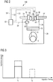
- FIG. 2 an exemplary embodiment of a control system 100 for adjusting an amount of injected liquid fuel and/or an injection timing of said liquid fuel is shown.
- the person skilled in the art will recognize that the exemplary cylinder 26 shown in Fig. 2 demonstrates the principles of the cylinders 26A-26D of Fig. 1 . Therefore, the exemplary disclosed configuration shown in Fig. 2 also applies to the cylinders 26A-26D shown in Fig. 1 .
- Fig. 2 shows a schematic cross-sectional view of cylinder 26.
- Cylinder 26 defines a combustion chamber 16 and includes a piston 18.
- Crank-shaft 6 is connected to piston 18 via piston rod 8.
- Piston 18 is configured to reciprocate within cylinder 26.
- Cylinder 26 is connected to intake manifold 22 ( Fig. 1 ) via intake passage 24 and to exhaust manifold 28 via exhaust passage 37.
- Inlet valve 35 is disposed in intake passage 24, and exhaust valve 36 is disposed in exhaust passage 37.
- Gas admission valve 38 is provided to supply gaseous fuel to combustion chamber 16 of cylinder 26 in the gas mode.
- gas admission valve 38 may be a solenoid-operated gas admission valve (SOGAV).
- Liquid fuel main injector 70 is provided to supply a main liquid fuel injection to combustion chamber 16 of cylinder 26 in the liquid fuel mode.
- main injector 70 may be configured to receive a desired amount of liquid fuel from a fuel pump (not shown) associated with cylinder 26, and to inject the received liquid fuel at a desired main injection timing.
- Inlet valve 35 is configured to supply compressed intake air to combustion chamber 16.
- Exhaust valve 36 is configured to discharge exhaust from combustion chamber 16 to exhaust manifold 28 after combustion.
- Injection device 90 is configured to ignite the mixture of gaseous fuel and air (when operating in gas mode) or to improve the combustion of main liquid fuel, for example, diesel fuel (when operating in liquid fuel mode) inside combustion chamber 16 at a desired ignition timing.
- injection device 90 is a pilot injector configured to inject a pilot amount of, for example, diesel fuel to ignite the mixture of gaseous fuel and air in the gas mode.
- Injection device 90 may further be used to inject a pilot amount of liquid fuel in the liquid fuel mode, for example, to assist the combustion of the main liquid fuel injected by liquid fuel main injector 70.
- a pre-combustion chamber (not shown) may be provided in combustion chamber 16, and injection device 90 may be configured to ignite a small amount of fuel supplied to the pre-combustion chamber in order to initiate the combustion of the mixture of fuel and air in combustion chamber 16.
- Control system 100 includes a sensor 60 associated with cylinder 26.
- Sensor 60 may be disposed at least in part within combustion chamber 16. In other exemplary embodiments, sensor 60 may be disposed outside of combustion chamber 16. Sensor 60 is configured to detect a parameter of the combustion in cylinder 26.
- sensor 60 may be a pressure sensor configured to detect a cylinder pressure in cylinder 26. Sensor 60 may be any known pressure sensor and may be configured to detect the pressure within combustion chamber 16 in a known manner. In other embodiments, sensor 60 may be configured to detect temperature fluctuations within combustion chamber 16 or other parameters from which characteristics of the combustion in combustion chamber 16 can be derived.
- sensor 60 may be an impact sound sensor configured to detect an impact sound propagating in engine block 20 during combustion in combustion chamber 16.
- Control system 100 further includes a control unit 50.
- Control unit 50 is connected to sensor 60 via a communication line 54 and to gas admission valve 38 via a communication line 52.
- Control unit 50 is further connected to injection device 90 via a communication line 53 and to main injector 70 via a communication line 55.
- Control unit 50 is configured to control an ignition timing of the mixture in combustion chamber 16 via injection device 90 by injecting a predetermined amount of liquid fuel at a predetermined injection timing.
- control unit 50 is configured to receive the results of the detection by sensor 60 and to determine at least one characteristic of the combustion in combustion chamber 16 from the received detection results.
- Control unit 50 may be a single microprocessor or dual microprocessors that include means for controlling, among others, an operation of various components of combustion engine 10.
- Control unit 50 may be a general engine control unit (ECU) capable of controlling internal combustion engine 10 and/or its associated components.
- Control unit 50 may include all components required to run an application such as, for example, a memory, a secondary storage device, and a processor such as a central processing unit or any other means known in the art for controlling internal combustion engine 10 and its components.
- Various other known circuits may be associated with control unit 50, including power supply circuitry, signal conditioning circuitry, communication circuitry and other appropriate circuitry.
- Control unit 50 may analyze and compare received and stored data and, based on instructions and data stored in memory or input by a user, determine whether action is required. For example, control unit 50 may compare received values with target values stored in memory, and, based on the results of the comparison, transmit signals to one or more components to alter the operation status of the same.
- Control unit 50 may include any memory device known in the art for storing data relating to operation of internal combustion engine 10 and its components.
- the data may be stored in the form of one or more maps that describe and/or relate, for example, the detection results from sensor 60 to a combustion profile of the combustion in combustion chamber 16.
- Each of the maps may be in the form of tables, graphs and/or equations, and may include a compilation of data collected from lab and/or field operation of internal combustion engine 10.
- the maps may be generated by performing instrumented tests on the operation of internal combustion engine 10 under various operating conditions while varying parameters associated therewith or performing various measurements.
- Control unit 50 may reference these maps and control operation of one component in response to the desired operation of another component.
- control unit 50 has one or more combustion profiles for cylinder 26 stored in the memory of the same, said combustion profiles being determined in advance for a standard or reference operating condition of internal combustion engine 10.
- each reference combustion profile is determined under a reference operating condition that specifies one or more of a reference fuel quality of the gaseous fuel, a reference fuel quality of the liquid fuel, a reference ambient air temperature, a reference ambient air pressure, a reference humidity, a reference engine load, and a reference number of injections by injection device 90 with associated injection timings and injection amounts.
- internal combustion engine 10 may be operated with standard fuel of known quality under standard or known ambient conditions such as air temperature, air pressure, humidity, etc.
- injection timings and injection amounts for one or more injections by injection device 90 may be varied, until an optimum combustion is obtained.
- NOx values associated with the combustion may be taken into account when determining the optimum number of injections and/or injection amounts.
- one or more maps can be obtained that associate optimum injection timings and injection amounts with, for example, given ambient conditions, a given fuel quality, or a given engine load.
- internal combustion engine 10 may be operated using a number of injections and corresponding injection amounts for a given ambient air temperature, ambient air pressure, humidity etc. as defined in one of the maps stored in the memory of control unit 50. Further, a corresponding reference combustion profile is selected in accordance with this current operating condition of internal combustion engine 10.
- one or more measurements relating to the combustion in combustion chamber 16 of cylinder 26 are performed.
- the measurement by pressure sensor 60 is used to determine at least one combustion parameter, for example, a start of combustion, a center of combustion and/or a combustion duration of the associated combustion event.
- other measurements may be used as an alternative or in addition to the cylinder pressure measurements.
- a measurement of the exhaust temperature may be used to determine whether a combustion characteristic or parameter is in agreement with a desired combustion characteristic or parameter.
- control unit 50 is configured to compare the at least one combustion parameter based on the at least one measurement to a desired or reference combustion parameter associated with the selected reference combustion profile. Further, control unit 50 is configured to determine whether the determined combustion parameter differs from the desired combustion parameter, for example, by more than a predetermined amount. If so, control unit 50 is configured to adjust an amount of liquid fuel injected by injection device 90 and/or an injection timing of the liquid fuel in a subsequent combustion cycle. This will be described in more detail with reference to Fig. 3 .
- control unit 50 may be configured to control injection device 90 to inject a first amount of liquid fuel at a first injection timing t 1 in a combustion cycle of internal combustion engine 10 (solid line in Fig. 3 ).
- the injection at timing t 1 is the only injection. It will be appreciated, however, that two or more injections may be performed, with the first amount of liquid fuel being defined by the total amount of liquid fuel injected in the plurality of injections.
- control unit 50 may be configured to determine the duration of combustion or the start of combustion.
- control unit 50 may be configured to increase the amount of ignition fuel that is injected in response to such a determination.
- the increase in the amount of ignition fuel may be proportional to the difference.
- control unit 50 may be configured to increase the amount of liquid fuel injected at injection timing t 1 in order to reduce the duration of combustion to the duration of the selected reference combustion profile (dashed line in Fig. 3 ).
- control unit 50 may determine the start of combustion from the measured cylinder pressure, and in case it is determined that the start of combustion is retarded by more than a predetermined amount with respect to the start of combustion associated with the reference combustion profile, control unit 50 may be configured to perform an additional injection using injection device 90 (dot-dashed line in Fig. 3 ). It is obvious that this also results in an increase in the total amount of liquid fuel that is injected by injection device 90 at timings t 1 and t 2 .
- any appropriate combination of reducing/increasing a number of injections and reducing/increasing an amount of liquid fuel injected at a given injection timing can be used in order to take the appropriate measures for bringing the combustion profile or combustion parameter that is determined based on measurement in line with the desired reference combustion parameter or profile.
- control unit 50 may also be configured to use the NOx values determined by exhaust sensor 29 in order to perform further adjustments of the amount of liquid fuel injected by the injection device 90 and/or the injection timing(s) of the liquid fuel based at least in part on the measured NOx content. Further, in some embodiments, control unit 50 may be configured to increase a charge air pressure when the measured NOx content exceeds a predetermined upper NOx threshold, or to decrease the charge air pressure when the measured NOx content falls below a predetermined lower NOx threshold.
- control unit 50 is configured to adjust the amount of liquid fuel and/or the injection timing(s) in a subsequent combustion cycle when the determined combustion parameter differs from the desired or reference combustion parameter, for example, by more than a predetermined amount.
- the cycle in which the adjusted amount of liquid fuel and/or the adjusted injection timing(s) are used is the combustion cycle immediately following the combustion cycle during which the combustion parameter was determined.
- control unit 50 may be configured to perform said measurements over a plurality of combustion cycles, in order to eliminate excessive adjustments due to fluctuations in the measurements or in the operation of the engine, for example, during transients.
- control unit 50 may be configured to perform the measurement and compare the determined combustion parameter to the desired combustion parameter over two to fifty combustion cycles, and only perform the adjustment when the combustion parameter differs from the desired combustion parameter by more than the predetermined amount in a predetermined number of combustion cycles, for example, three to eight combustion cycles.
- An exemplary machine suited to the disclosure is a large internal combustion engine such as the engines of the series M46DF, M43DF, M32DF, M34DF, M27DF, M3x manufactured by Caterpillar Motoren GmbH & Co. KG, Kiel, Germany.
- the systems and methods described herein can be adapted to a large variety of other gas or dual fuel engines used for various different tasks.
- control unit 50 injects a first amount of liquid fuel via injection device 90 in a combustion cycle of internal combustion engine 10. For example, as shown in Fig. 3 , control unit 50 injects a first amount of liquid fuel at a first injection timing t 1 to combust the mixture of gaseous fuel and air in combustion chamber 16 of cylinder 26.
- control unit 50 determines at least one combustion parameter associated with the combustion in combustion chamber 16. For example, control unit 50 may determine a duration of combustion or a start of combustion.
- control unit 50 compares the at least one combustion parameter to a desired combustion parameter associated with a selected reference combustion profile that has been determined in advance and for which the combustion is known to be optimum, for example, with respect to reliability of combustion and NOx emissions.
- Said reference combustion profile may be selected based, for example, on current ambient conditions under which internal combustion engine 10 operates, and/or based on a current engine load.
- control unit 50 determines that the combustion parameter differs from the desired combustion parameter by more than a predetermined amount, control unit 50 adjusts at least one of an amount of liquid fuel supplied by injection device 90 and an injection timing of the liquid fuel in a subsequent combustion cycle of internal combustion engine 10. For example, as shown in Fig. 3 , when control unit 50 determines that the DOC exceeds the DOC of the reference combustion profile by more than a predetermined amount, control unit 50 may increase the amount of ignition fuel supplied to cylinder 26 proportional to this difference. To this end, control unit 50 may increase the amount of liquid fuel injected at injection timing t 1 , as shown by the dashed line in Fig. 3 .
- control unit 50 may control injection device 90 to perform an additional injection at injection timing t 2 (dot-dashed line in Fig. 2 ).
- control unit 50 may be configured to use an arbitrary combination of increasing or decreasing injection amounts at one or more injection timings, and increasing/decreasing the number of injections at different injection timings.
- the at least one combustion parameter (or the associated combustion profile) may be brought in line with the desired combustion parameter or profile during operation of internal combustion engine 10.
- the present embodiment has been described as using the cylinder pressure sensor 60 associated with each cylinder or the pluralities of cylinders of internal combustion engine 10 in order to determine the at least one combustion parameter, in other embodiments, different measurements may be used to determine said parameter. For example, it may be possible to use the exhaust gas temperature measured by exhaust sensor 29 to derive the parameter.
Landscapes
- Engineering & Computer Science (AREA)
- Chemical & Material Sciences (AREA)
- Combustion & Propulsion (AREA)
- Mechanical Engineering (AREA)
- General Engineering & Computer Science (AREA)
- Oil, Petroleum & Natural Gas (AREA)
- Electrical Control Of Air Or Fuel Supplied To Internal-Combustion Engine (AREA)
Claims (13)
- Verfahren zum Betreiben eines Verbrennungsmotors (10) mit gasförmigem Kraftstoff, wobei der Verbrennungsmotor eine Einspritzvorrichtung (90) umfasst, die konfiguriert ist, einem Zylinder (26) des Verbrennungsmotors (10) eine Voreinspritzung eines flüssigen Kraftstoffs zur Verbrennung mit einer Mischung aus gasförmigem Kraftstoff und Luft in einer Brennkammer (16) des Zylinders (26) zuzuführen, wobei das Verfahren umfasst:Einführen einer Mischung aus gasförmigem Kraftstoff und Luft in die Brennkammer (16);Einspritzen einer ersten Menge flüssigen Kraftstoffs in den Brennraum (16) über die Einspritzvorrichtung (90) in einem Verbrennungszyklus des Verbrennungsmotors (10);Durchführen mindestens einer Messung in Bezug auf die Verbrennung der ersten Menge an flüssigem Kraftstoff und des Gemischs aus gasförmigem Kraftstoff und Luft in der Brennkammer (16);Bestimmen mindestens eines Verbrennungsparameters basierend auf der mindestens einen Messung;Vergleichen des Verbrennungsparameters mit einem gewünschten Verbrennungsparameter; undEinstellen mindestens eines von einer Menge an flüssigem Kraftstoff, die von der Einspritzvorrichtung (90) eingespritzt wird, und einem Einspritzzeitpunkt des flüssigen Kraftstoffs in einem nachfolgenden Verbrennungszyklus, wenn sich der Verbrennungsparameter von dem gewünschten Verbrennungsparameter um mehr als einen vorbestimmten Betrag unterscheidet, dadurch gekennzeichnet, dass der Schritt des Bestimmens des mindestens einen Verbrennungsparameters das Bestimmen eines Verbrennungsprofils für den Zylinder (26) basierend auf der mindestens einen Messung umfasst,wobei der Schritt des Vergleichens des Verbrennungsparameters mit einem gewünschten Verbrennungsparameter das Vergleichen des Verbrennungsprofils mit einem Referenzverbrennungsprofil umfasst, das im Voraus für einen Referenzbetriebszustand des Verbrennungsmotors (10) bestimmt wurde, undwobei eine Vielzahl von Referenzverbrennungsprofilen bereitgestellt wird, wobei das Verfahren ferner das Auswählen eines der Vielzahl von Referenzverbrennungsprofilen basierend auf einem aktuellen Betriebszustand des Verbrennungsmotors (10) umfasst, wobei der aktuelle Betriebszustand mindestens eines von einer Kraftstoffqualität des gasförmigen Kraftstoffs, einer Kraftstoffqualität des flüssigen Kraftstoffs, einer Umgebungslufttemperatur, einem Umgebungsluftdruck, einer Umgebungsluftfeuchtigkeit und einer Motorlast spezifiziert.
- Verfahren nach Anspruch 1, ferner umfassend:
Einstellen einer Anzahl von Einspritzungen durch die Einspritzvorrichtung (90) in dem nachfolgenden Verbrennungszyklus, wenn sich der Verbrennungsparameter von dem gewünschten Verbrennungsparameter um mehr als den vorbestimmten Betrag unterscheidet. - Verfahren nach Anspruch 2, ferner umfassend:Bestimmen eines Verbrennungsbeginns in dem Zylinder (26) basierend auf der mindestens einen Messung; undErhöhen der Anzahl von Einspritzungen durch die Einspritzvorrichtung (90) in dem nachfolgenden Verbrennungszyklus, wenn der Verbrennungsbeginn in Bezug auf einen gewünschten Verbrennungsbeginn verzögert ist.
- Verfahren nach einem der Ansprüche 1 bis 3, ferner umfassend:Bestimmen einer Verbrennungsdauer in dem Zylinder (26) basierend auf der mindestens einen Messung; undErhöhen der Menge an flüssigem Kraftstoff, die durch die Einspritzvorrichtung (90) in dem nachfolgenden Verbrennungszyklus eingespritzt wird, wenn die Verbrennungsdauer länger als eine gewünschte Verbrennungsdauer ist.
- Verfahren nach einem der Ansprüche 1 bis 4, ferner umfassend das Bestimmen eines Verbrennungsmittelpunkts basierend auf der mindestens einen Messung; und
Einstellen der mindestens einen von einer Menge an flüssigem Kraftstoff, die von der Einspritzvorrichtung (90) eingespritzt wird, und einem Einspritzzeitpunkt des flüssigen Kraftstoffs in einem nachfolgenden Verbrennungszyklus, wenn der Verbrennungsmittelpunkt von einem gewünschten Verbrennungsmittelpunkt abweicht. - Verfahren nach Anspruch 1, wobei der Referenzbetriebszustand mindestens eines von einer Kraftstoffqualität des gasförmigen Kraftstoffs, einer Kraftstoffqualität des flüssigen Kraftstoffs, einer Umgebungslufttemperatur, einem Umgebungsluftdruck, einer Umgebungsluftfeuchtigkeit und einer Motorlast spezifiziert.
- Verfahren nach einem der Ansprüche 1 bis 6, wobei die mindestens eine Messung eine Zylinderdruckmessung und/oder eine Zylindertemperaturmessung umfasst.
- Verfahren nach einem der Ansprüche 1 bis 7, wobei die mindestens eine Messung eine Abgastemperaturmessung umfasst.
- Verfahren nach einem der Ansprüche 1 bis 8, ferner umfassend:Messen eines NOx-Gehalts im Abgas aus dem Zylinder (26); undEinstellen des mindestens einen von einer Menge an flüssigem Kraftstoff, die von der Einspritzvorrichtung (90) eingespritzt wird, und einem Einspritzzeitpunkt des flüssigen Kraftstoffs zumindest teilweise basierend auf dem gemessenen NOx-Gehalt.
- Verfahren nach Anspruch 9, ferner umfassend:
Erhöhen eines Ladeluftdrucks, wenn der gemessene NOx-Gehalt einen vorbestimmten oberen NOx-Schwellenwert überschreitet, und/oder Verringern des Ladeluftdrucks, wenn der gemessene NOx-Gehalt unter einen vorbestimmten unteren NOx-Schwellenwert fällt. - Verfahren nach einem der Ansprüche 1 bis 10, ferner umfassend:Durchführen der mindestens einen Messung und Vergleichen des Verbrennungsparameters mit dem gewünschten Verbrennungsparameter über eine Vielzahl von Verbrennungszyklen; undEinstellen des mindestens einen von der Menge an flüssigem Kraftstoff, die von der Einspritzvorrichtung (90) zugeführt wird, und einem Zeitpunkt der Zufuhr des flüssigen Kraftstoffs nur dann, wenn sich der Verbrennungsparameter von dem gewünschten Verbrennungsparameter um mehr als den vorbestimmten Betrag in einer vorbestimmten Anzahl von Verbrennungszyklen unterscheidet.
- Computerprogramm, umfassend computerausführbare Anweisungen, die, wenn sie auf einem Computer ausgeführt werden, bewirken, dass der Computer die Schritte des Verfahrens nach einem der Ansprüche 1 bis 11 ausführt.
- Verbrennungsmotor (10), umfassend:einen Motorblock (20), der zumindest teilweise einen Zylinder (26) definiert;eine Einspritzvorrichtung (90), die konfiguriert ist, um dem Zylinder (26) eine Voreinspritzung eines flüssigen Kraftstoffs zur Verbrennung mit einem Gemisch von gasförmigem Kraftstoff und Luft in einer Brennkammer (16) des Zylinders (26) zuzuführen; undeine Steuereinheit (50), die konfiguriert ist zum:Einspritzen einer ersten Menge flüssigen Kraftstoffs über die Einspritzvorrichtung (90) in einem Verbrennungszyklus des Verbrennungsmotors (10);Durchführen mindestens einer Messung in Bezug auf die Verbrennung der ersten Menge an flüssigem Kraftstoff und des Gemischs aus gasförmigem Kraftstoff und Luft in der Brennkammer (16);Bestimmen mindestens eines Verbrennungsparameters basierend auf der mindestens einen Messung;Vergleichen des Verbrennungsparameters mit einem gewünschten Verbrennungsparameter; undEinstellen mindestens eines von einer Menge an flüssigem Kraftstoff, die von der Einspritzvorrichtung (90) eingespritzt wird, und einem Einspritzzeitpunkt des flüssigen Kraftstoffs in einem nachfolgenden Verbrennungszyklus, wenn sich der Verbrennungsparameter von dem gewünschten Verbrennungsparameter um mehr als einen vorbestimmten Betrag unterscheidet,dadurch gekennzeichnet, dass die Steuereinheit (50) ferner konfiguriert ist zum:Bestimmen eines Verbrennungsprofils für den Zylinder (26) basierend auf der mindestens einen Messung; undVergleichen des Verbrennungsprofils mit einem Referenzverbrennungsprofil, das im Voraus für einen Referenzbetriebszustand des Verbrennungsmotors (10) bestimmt wurde,und wobei eine Vielzahl von Referenzverbrennungsprofilen bereitgestellt wird, die Steuereinheit (50) ferner konfiguriert ist, eines der Vielzahl von Referenzverbrennungsprofilen basierend auf einem aktuellen Betriebszustand des Verbrennungsmotors (10) auszuwählen, wobei der aktuelle Betriebszustand mindestens eines von einer Kraftstoffqualität des gasförmigen Kraftstoffs, einer Kraftstoffqualität des flüssigen Kraftstoffs, einer Umgebungslufttemperatur, einem Umgebungsluftdruck, einer Umgebungsluftfeuchtigkeit und einer Motorlast spezifiziert.
Priority Applications (1)
| Application Number | Priority Date | Filing Date | Title |
|---|---|---|---|
| EP16204329.3A EP3336337B1 (de) | 2016-12-15 | 2016-12-15 | Verfahren zum betreiben eines verbrennungsmotors mit gasförmigem brennstoff |
Applications Claiming Priority (1)
| Application Number | Priority Date | Filing Date | Title |
|---|---|---|---|
| EP16204329.3A EP3336337B1 (de) | 2016-12-15 | 2016-12-15 | Verfahren zum betreiben eines verbrennungsmotors mit gasförmigem brennstoff |
Publications (2)
| Publication Number | Publication Date |
|---|---|
| EP3336337A1 EP3336337A1 (de) | 2018-06-20 |
| EP3336337B1 true EP3336337B1 (de) | 2021-01-27 |
Family
ID=57590331
Family Applications (1)
| Application Number | Title | Priority Date | Filing Date |
|---|---|---|---|
| EP16204329.3A Active EP3336337B1 (de) | 2016-12-15 | 2016-12-15 | Verfahren zum betreiben eines verbrennungsmotors mit gasförmigem brennstoff |
Country Status (1)
| Country | Link |
|---|---|
| EP (1) | EP3336337B1 (de) |
Families Citing this family (4)
| Publication number | Priority date | Publication date | Assignee | Title |
|---|---|---|---|---|
| US11035317B2 (en) * | 2019-06-06 | 2021-06-15 | Caterpillar Inc. | Controlling pilot fuel injection in an engine |
| DE102021200464B4 (de) * | 2021-01-19 | 2022-09-15 | Rolls-Royce Solutions GmbH | Verfahren zum Betreiben einer Brennkraftmaschine und Brennkraftmaschine |
| US11639698B1 (en) * | 2022-04-11 | 2023-05-02 | Caterpillar Inc. | Compression-ignited dual liquid fuel system and control strategy for flexible fuel operation |
| DE102022121793A1 (de) * | 2022-08-29 | 2024-02-29 | Universität Rostock, Körperschaft des öffentlichen Rechts | Verfahren zum Regeln eines Zweistoffmotors sowie Zweistoffmotor |
Citations (3)
| Publication number | Priority date | Publication date | Assignee | Title |
|---|---|---|---|---|
| US5229946A (en) * | 1991-08-19 | 1993-07-20 | Motorola, Inc. | Method for optimizing engine performance for different blends of fuel |
| US20050177300A1 (en) * | 2004-02-09 | 2005-08-11 | Gunther Herdin | Method of regulating an internal combustion engine |
| EP2806145A1 (de) * | 2013-05-24 | 2014-11-26 | Caterpillar Motoren GmbH & Co. KG | Verfahren zum Betreiben eines Gas- oder Zweistoffmotors |
Family Cites Families (8)
| Publication number | Priority date | Publication date | Assignee | Title |
|---|---|---|---|---|
| US6289871B1 (en) * | 1998-03-06 | 2001-09-18 | Caterpillar Inc. | Method for achieving minimum liquid pilot fuel delivery to each cylinder of a dual fuel engine while operating in a dual fuel mode |
| JP2014525533A (ja) * | 2011-08-09 | 2014-09-29 | クリーン エア パワー, インコーポレーテッド | 複数モードエンジンにおける前混合燃焼を制御するための方法及び装置 |
| FI124730B (en) * | 2013-01-22 | 2014-12-31 | Wärtsilä Finland Oy | A method of operating a piston engine and a piston engine |
| US9334813B2 (en) * | 2013-01-31 | 2016-05-10 | Electro-Motive Diesel, Inc. | Control system for a dual-fuel engine |
| US10465616B2 (en) * | 2013-08-05 | 2019-11-05 | Achates Power, Inc. | Dual-fuel constructions for opposed-piston engines with shaped combustion chambers |
| US20150285178A1 (en) | 2014-04-02 | 2015-10-08 | Caterpillar Inc. | Reactivity controlled compression ignition engine and method of combustion phasing control |
| US9441561B2 (en) * | 2014-12-11 | 2016-09-13 | Caterpillar Inc. | System and method for increasing tolerance to fuel variation |
| US20160169133A1 (en) * | 2014-12-11 | 2016-06-16 | Caterpillar Inc. | System and method for increasing gaseous fuel substitution |
-
2016
- 2016-12-15 EP EP16204329.3A patent/EP3336337B1/de active Active
Patent Citations (3)
| Publication number | Priority date | Publication date | Assignee | Title |
|---|---|---|---|---|
| US5229946A (en) * | 1991-08-19 | 1993-07-20 | Motorola, Inc. | Method for optimizing engine performance for different blends of fuel |
| US20050177300A1 (en) * | 2004-02-09 | 2005-08-11 | Gunther Herdin | Method of regulating an internal combustion engine |
| EP2806145A1 (de) * | 2013-05-24 | 2014-11-26 | Caterpillar Motoren GmbH & Co. KG | Verfahren zum Betreiben eines Gas- oder Zweistoffmotors |
Also Published As
| Publication number | Publication date |
|---|---|
| EP3336337A1 (de) | 2018-06-20 |
Similar Documents
| Publication | Publication Date | Title |
|---|---|---|
| KR102416019B1 (ko) | 가스형 연료 내연 기관을 작동하는 방법 | |
| EP2907993B1 (de) | Verfahren zur Zylindergleichstellung einer Brennkraftmaschine | |
| EP2927467B1 (de) | Gas- oder Zweibrennstoffmaschine | |
| EP2806145B1 (de) | Verfahren zum Betreiben eines Gas- oder Zweistoffmotors | |
| EP3502445B1 (de) | Verfahren zum starten eines gasförmigen brennstoffverbrennungsmotors | |
| EP2511505B1 (de) | Verbrennungssteuerungsvorrichtung | |
| US20190120163A1 (en) | Dual-fuel internal combustion engine | |
| EP3336337A1 (de) | Verfahren zum betrieb eines verbrennungsmotors mit gasförmigem brennstoff | |
| EP3279453B1 (de) | Verfahren zum testen einer zündvorrichtung einer brennkraftmaschine | |
| EP2743482B1 (de) | Klopfsteuerungssystem, Verbrennungsmotor und Betriebsverfahren dafür | |
| KR102581651B1 (ko) | 대형 2행정 터보차지 유니플로 스캐빈지 내부 연소 엔진 및 엔진 작동 방법 | |
| US9284936B2 (en) | Method and device for controlling the exhaust gas recirculation rate for internal combustion engines during lean operation | |
| EP3282111B1 (de) | Verfahren zum starten eines gasförmigen brennstoffverbrennungsmotors | |
| EP3418541B1 (de) | Verfahren zur steuerung der verbrennung in motoren | |
| EP3282112B1 (de) | Motorsteuerung für vorgänge mit deaktivierten zylindern | |
| EP2910756A1 (de) | Ausgeglichener Zylinderbetrieb von Verbrennungsmotoren | |
| EP3336338A1 (de) | Fehlzündungserkennung für mit deaktivierten zylindern laufende brennkraftmaschine |
Legal Events
| Date | Code | Title | Description |
|---|---|---|---|
| PUAI | Public reference made under article 153(3) epc to a published international application that has entered the european phase |
Free format text: ORIGINAL CODE: 0009012 |
|
| STAA | Information on the status of an ep patent application or granted ep patent |
Free format text: STATUS: THE APPLICATION HAS BEEN PUBLISHED |
|
| AK | Designated contracting states |
Kind code of ref document: A1 Designated state(s): AL AT BE BG CH CY CZ DE DK EE ES FI FR GB GR HR HU IE IS IT LI LT LU LV MC MK MT NL NO PL PT RO RS SE SI SK SM TR |
|
| AX | Request for extension of the european patent |
Extension state: BA ME |
|
| STAA | Information on the status of an ep patent application or granted ep patent |
Free format text: STATUS: REQUEST FOR EXAMINATION WAS MADE |
|
| 17P | Request for examination filed |
Effective date: 20181219 |
|
| RBV | Designated contracting states (corrected) |
Designated state(s): AL AT BE BG CH CY CZ DE DK EE ES FI FR GB GR HR HU IE IS IT LI LT LU LV MC MK MT NL NO PL PT RO RS SE SI SK SM TR |
|
| STAA | Information on the status of an ep patent application or granted ep patent |
Free format text: STATUS: EXAMINATION IS IN PROGRESS |
|
| 17Q | First examination report despatched |
Effective date: 20200130 |
|
| GRAP | Despatch of communication of intention to grant a patent |
Free format text: ORIGINAL CODE: EPIDOSNIGR1 |
|
| STAA | Information on the status of an ep patent application or granted ep patent |
Free format text: STATUS: GRANT OF PATENT IS INTENDED |
|
| INTG | Intention to grant announced |
Effective date: 20200908 |
|
| GRAJ | Information related to disapproval of communication of intention to grant by the applicant or resumption of examination proceedings by the epo deleted |
Free format text: ORIGINAL CODE: EPIDOSDIGR1 |
|
| GRAP | Despatch of communication of intention to grant a patent |
Free format text: ORIGINAL CODE: EPIDOSNIGR1 |
|
| STAA | Information on the status of an ep patent application or granted ep patent |
Free format text: STATUS: EXAMINATION IS IN PROGRESS |
|
| GRAJ | Information related to disapproval of communication of intention to grant by the applicant or resumption of examination proceedings by the epo deleted |
Free format text: ORIGINAL CODE: EPIDOSDIGR1 |
|
| GRAP | Despatch of communication of intention to grant a patent |
Free format text: ORIGINAL CODE: EPIDOSNIGR1 |
|
| GRAS | Grant fee paid |
Free format text: ORIGINAL CODE: EPIDOSNIGR3 |
|
| STAA | Information on the status of an ep patent application or granted ep patent |
Free format text: STATUS: GRANT OF PATENT IS INTENDED |
|
| GRAA | (expected) grant |
Free format text: ORIGINAL CODE: 0009210 |
|
| STAA | Information on the status of an ep patent application or granted ep patent |
Free format text: STATUS: THE PATENT HAS BEEN GRANTED |
|
| INTC | Intention to grant announced (deleted) | ||
| INTG | Intention to grant announced |
Effective date: 20200908 |
|
| AK | Designated contracting states |
Kind code of ref document: B1 Designated state(s): AL AT BE BG CH CY CZ DE DK EE ES FI FR GB GR HR HU IE IS IT LI LT LU LV MC MK MT NL NO PL PT RO RS SE SI SK SM TR |
|
| REG | Reference to a national code |
Ref country code: GB Ref legal event code: FG4D |
|
| REG | Reference to a national code |
Ref country code: CH Ref legal event code: EP |
|
| REG | Reference to a national code |
Ref country code: DE Ref legal event code: R096 Ref document number: 602016052006 Country of ref document: DE |
|
| REG | Reference to a national code |
Ref country code: AT Ref legal event code: REF Ref document number: 1358556 Country of ref document: AT Kind code of ref document: T Effective date: 20210215 |
|
| REG | Reference to a national code |
Ref country code: IE Ref legal event code: FG4D |
|
| REG | Reference to a national code |
Ref country code: FI Ref legal event code: FGE |
|
| REG | Reference to a national code |
Ref country code: NL Ref legal event code: MP Effective date: 20210127 |
|
| REG | Reference to a national code |
Ref country code: LT Ref legal event code: MG9D |
|
| REG | Reference to a national code |
Ref country code: AT Ref legal event code: MK05 Ref document number: 1358556 Country of ref document: AT Kind code of ref document: T Effective date: 20210127 |
|
| PG25 | Lapsed in a contracting state [announced via postgrant information from national office to epo] |
Ref country code: GR Free format text: LAPSE BECAUSE OF FAILURE TO SUBMIT A TRANSLATION OF THE DESCRIPTION OR TO PAY THE FEE WITHIN THE PRESCRIBED TIME-LIMIT Effective date: 20210428 Ref country code: HR Free format text: LAPSE BECAUSE OF FAILURE TO SUBMIT A TRANSLATION OF THE DESCRIPTION OR TO PAY THE FEE WITHIN THE PRESCRIBED TIME-LIMIT Effective date: 20210127 Ref country code: NO Free format text: LAPSE BECAUSE OF FAILURE TO SUBMIT A TRANSLATION OF THE DESCRIPTION OR TO PAY THE FEE WITHIN THE PRESCRIBED TIME-LIMIT Effective date: 20210427 Ref country code: PT Free format text: LAPSE BECAUSE OF FAILURE TO SUBMIT A TRANSLATION OF THE DESCRIPTION OR TO PAY THE FEE WITHIN THE PRESCRIBED TIME-LIMIT Effective date: 20210527 Ref country code: BG Free format text: LAPSE BECAUSE OF FAILURE TO SUBMIT A TRANSLATION OF THE DESCRIPTION OR TO PAY THE FEE WITHIN THE PRESCRIBED TIME-LIMIT Effective date: 20210427 Ref country code: LT Free format text: LAPSE BECAUSE OF FAILURE TO SUBMIT A TRANSLATION OF THE DESCRIPTION OR TO PAY THE FEE WITHIN THE PRESCRIBED TIME-LIMIT Effective date: 20210127 |
|
| PG25 | Lapsed in a contracting state [announced via postgrant information from national office to epo] |
Ref country code: SE Free format text: LAPSE BECAUSE OF FAILURE TO SUBMIT A TRANSLATION OF THE DESCRIPTION OR TO PAY THE FEE WITHIN THE PRESCRIBED TIME-LIMIT Effective date: 20210127 Ref country code: AT Free format text: LAPSE BECAUSE OF FAILURE TO SUBMIT A TRANSLATION OF THE DESCRIPTION OR TO PAY THE FEE WITHIN THE PRESCRIBED TIME-LIMIT Effective date: 20210127 Ref country code: RS Free format text: LAPSE BECAUSE OF FAILURE TO SUBMIT A TRANSLATION OF THE DESCRIPTION OR TO PAY THE FEE WITHIN THE PRESCRIBED TIME-LIMIT Effective date: 20210127 Ref country code: PL Free format text: LAPSE BECAUSE OF FAILURE TO SUBMIT A TRANSLATION OF THE DESCRIPTION OR TO PAY THE FEE WITHIN THE PRESCRIBED TIME-LIMIT Effective date: 20210127 Ref country code: LV Free format text: LAPSE BECAUSE OF FAILURE TO SUBMIT A TRANSLATION OF THE DESCRIPTION OR TO PAY THE FEE WITHIN THE PRESCRIBED TIME-LIMIT Effective date: 20210127 |
|
| PG25 | Lapsed in a contracting state [announced via postgrant information from national office to epo] |
Ref country code: IS Free format text: LAPSE BECAUSE OF FAILURE TO SUBMIT A TRANSLATION OF THE DESCRIPTION OR TO PAY THE FEE WITHIN THE PRESCRIBED TIME-LIMIT Effective date: 20210527 |
|
| REG | Reference to a national code |
Ref country code: DE Ref legal event code: R097 Ref document number: 602016052006 Country of ref document: DE |
|
| PG25 | Lapsed in a contracting state [announced via postgrant information from national office to epo] |
Ref country code: CZ Free format text: LAPSE BECAUSE OF FAILURE TO SUBMIT A TRANSLATION OF THE DESCRIPTION OR TO PAY THE FEE WITHIN THE PRESCRIBED TIME-LIMIT Effective date: 20210127 Ref country code: EE Free format text: LAPSE BECAUSE OF FAILURE TO SUBMIT A TRANSLATION OF THE DESCRIPTION OR TO PAY THE FEE WITHIN THE PRESCRIBED TIME-LIMIT Effective date: 20210127 Ref country code: SM Free format text: LAPSE BECAUSE OF FAILURE TO SUBMIT A TRANSLATION OF THE DESCRIPTION OR TO PAY THE FEE WITHIN THE PRESCRIBED TIME-LIMIT Effective date: 20210127 |
|
| PG25 | Lapsed in a contracting state [announced via postgrant information from national office to epo] |
Ref country code: RO Free format text: LAPSE BECAUSE OF FAILURE TO SUBMIT A TRANSLATION OF THE DESCRIPTION OR TO PAY THE FEE WITHIN THE PRESCRIBED TIME-LIMIT Effective date: 20210127 Ref country code: SK Free format text: LAPSE BECAUSE OF FAILURE TO SUBMIT A TRANSLATION OF THE DESCRIPTION OR TO PAY THE FEE WITHIN THE PRESCRIBED TIME-LIMIT Effective date: 20210127 Ref country code: DK Free format text: LAPSE BECAUSE OF FAILURE TO SUBMIT A TRANSLATION OF THE DESCRIPTION OR TO PAY THE FEE WITHIN THE PRESCRIBED TIME-LIMIT Effective date: 20210127 |
|
| PLBE | No opposition filed within time limit |
Free format text: ORIGINAL CODE: 0009261 |
|
| STAA | Information on the status of an ep patent application or granted ep patent |
Free format text: STATUS: NO OPPOSITION FILED WITHIN TIME LIMIT |
|
| 26N | No opposition filed |
Effective date: 20211028 |
|
| PG25 | Lapsed in a contracting state [announced via postgrant information from national office to epo] |
Ref country code: ES Free format text: LAPSE BECAUSE OF FAILURE TO SUBMIT A TRANSLATION OF THE DESCRIPTION OR TO PAY THE FEE WITHIN THE PRESCRIBED TIME-LIMIT Effective date: 20210127 Ref country code: AL Free format text: LAPSE BECAUSE OF FAILURE TO SUBMIT A TRANSLATION OF THE DESCRIPTION OR TO PAY THE FEE WITHIN THE PRESCRIBED TIME-LIMIT Effective date: 20210127 |
|
| PG25 | Lapsed in a contracting state [announced via postgrant information from national office to epo] |
Ref country code: SI Free format text: LAPSE BECAUSE OF FAILURE TO SUBMIT A TRANSLATION OF THE DESCRIPTION OR TO PAY THE FEE WITHIN THE PRESCRIBED TIME-LIMIT Effective date: 20210127 |
|
| PG25 | Lapsed in a contracting state [announced via postgrant information from national office to epo] |
Ref country code: IS Free format text: LAPSE BECAUSE OF FAILURE TO SUBMIT A TRANSLATION OF THE DESCRIPTION OR TO PAY THE FEE WITHIN THE PRESCRIBED TIME-LIMIT Effective date: 20210527 |
|
| PG25 | Lapsed in a contracting state [announced via postgrant information from national office to epo] |
Ref country code: MC Free format text: LAPSE BECAUSE OF FAILURE TO SUBMIT A TRANSLATION OF THE DESCRIPTION OR TO PAY THE FEE WITHIN THE PRESCRIBED TIME-LIMIT Effective date: 20210127 |
|
| REG | Reference to a national code |
Ref country code: CH Ref legal event code: PL |
|
| GBPC | Gb: european patent ceased through non-payment of renewal fee |
Effective date: 20211215 |
|
| REG | Reference to a national code |
Ref country code: BE Ref legal event code: MM Effective date: 20211231 |
|
| PG25 | Lapsed in a contracting state [announced via postgrant information from national office to epo] |
Ref country code: LU Free format text: LAPSE BECAUSE OF NON-PAYMENT OF DUE FEES Effective date: 20211215 Ref country code: IE Free format text: LAPSE BECAUSE OF NON-PAYMENT OF DUE FEES Effective date: 20211215 Ref country code: GB Free format text: LAPSE BECAUSE OF NON-PAYMENT OF DUE FEES Effective date: 20211215 |
|
| PG25 | Lapsed in a contracting state [announced via postgrant information from national office to epo] |
Ref country code: BE Free format text: LAPSE BECAUSE OF NON-PAYMENT OF DUE FEES Effective date: 20211231 |
|
| PG25 | Lapsed in a contracting state [announced via postgrant information from national office to epo] |
Ref country code: LI Free format text: LAPSE BECAUSE OF NON-PAYMENT OF DUE FEES Effective date: 20211231 Ref country code: CH Free format text: LAPSE BECAUSE OF NON-PAYMENT OF DUE FEES Effective date: 20211231 |
|
| PG25 | Lapsed in a contracting state [announced via postgrant information from national office to epo] |
Ref country code: HU Free format text: LAPSE BECAUSE OF FAILURE TO SUBMIT A TRANSLATION OF THE DESCRIPTION OR TO PAY THE FEE WITHIN THE PRESCRIBED TIME-LIMIT; INVALID AB INITIO Effective date: 20161215 |
|
| P01 | Opt-out of the competence of the unified patent court (upc) registered |
Effective date: 20230517 |
|
| PG25 | Lapsed in a contracting state [announced via postgrant information from national office to epo] |
Ref country code: NL Free format text: LAPSE BECAUSE OF NON-PAYMENT OF DUE FEES Effective date: 20210127 Ref country code: CY Free format text: LAPSE BECAUSE OF FAILURE TO SUBMIT A TRANSLATION OF THE DESCRIPTION OR TO PAY THE FEE WITHIN THE PRESCRIBED TIME-LIMIT Effective date: 20210127 |
|
| PG25 | Lapsed in a contracting state [announced via postgrant information from national office to epo] |
Ref country code: MK Free format text: LAPSE BECAUSE OF FAILURE TO SUBMIT A TRANSLATION OF THE DESCRIPTION OR TO PAY THE FEE WITHIN THE PRESCRIBED TIME-LIMIT Effective date: 20210127 |
|
| PG25 | Lapsed in a contracting state [announced via postgrant information from national office to epo] |
Ref country code: TR Free format text: LAPSE BECAUSE OF FAILURE TO SUBMIT A TRANSLATION OF THE DESCRIPTION OR TO PAY THE FEE WITHIN THE PRESCRIBED TIME-LIMIT Effective date: 20210127 |
|
| PG25 | Lapsed in a contracting state [announced via postgrant information from national office to epo] |
Ref country code: MT Free format text: LAPSE BECAUSE OF FAILURE TO SUBMIT A TRANSLATION OF THE DESCRIPTION OR TO PAY THE FEE WITHIN THE PRESCRIBED TIME-LIMIT Effective date: 20210127 |
|
| PGFP | Annual fee paid to national office [announced via postgrant information from national office to epo] |
Ref country code: DE Payment date: 20251126 Year of fee payment: 10 |
|
| PGFP | Annual fee paid to national office [announced via postgrant information from national office to epo] |
Ref country code: FI Payment date: 20251119 Year of fee payment: 10 Ref country code: IT Payment date: 20251119 Year of fee payment: 10 |
|
| PGFP | Annual fee paid to national office [announced via postgrant information from national office to epo] |
Ref country code: FR Payment date: 20251120 Year of fee payment: 10 |