EP3336357A1 - Pompe électrique - Google Patents
Pompe électrique Download PDFInfo
- Publication number
- EP3336357A1 EP3336357A1 EP17203992.7A EP17203992A EP3336357A1 EP 3336357 A1 EP3336357 A1 EP 3336357A1 EP 17203992 A EP17203992 A EP 17203992A EP 3336357 A1 EP3336357 A1 EP 3336357A1
- Authority
- EP
- European Patent Office
- Prior art keywords
- rotor
- pump
- outer rotor
- stator
- disposed
- Prior art date
- Legal status (The legal status is an assumption and is not a legal conclusion. Google has not performed a legal analysis and makes no representation as to the accuracy of the status listed.)
- Withdrawn
Links
- 230000006835 compression Effects 0.000 abstract description 6
- 238000007906 compression Methods 0.000 abstract description 6
- 238000005299 abrasion Methods 0.000 description 6
- 238000006073 displacement reaction Methods 0.000 description 6
- 238000000034 method Methods 0.000 description 5
- 238000007789 sealing Methods 0.000 description 5
- 230000013011 mating Effects 0.000 description 4
- 229910000831 Steel Inorganic materials 0.000 description 3
- 230000006866 deterioration Effects 0.000 description 3
- 239000010959 steel Substances 0.000 description 3
- 230000033001 locomotion Effects 0.000 description 2
- 238000005461 lubrication Methods 0.000 description 2
- 239000000696 magnetic material Substances 0.000 description 2
- 239000000463 material Substances 0.000 description 2
- 239000007769 metal material Substances 0.000 description 2
- 238000005086 pumping Methods 0.000 description 2
- 239000000853 adhesive Substances 0.000 description 1
- 230000001070 adhesive effect Effects 0.000 description 1
- 229910052782 aluminium Inorganic materials 0.000 description 1
- XAGFODPZIPBFFR-UHFFFAOYSA-N aluminium Chemical compound [Al] XAGFODPZIPBFFR-UHFFFAOYSA-N 0.000 description 1
- 230000005540 biological transmission Effects 0.000 description 1
- 239000002131 composite material Substances 0.000 description 1
- 238000001816 cooling Methods 0.000 description 1
- 230000004907 flux Effects 0.000 description 1
- 239000007788 liquid Substances 0.000 description 1
- 229910052751 metal Inorganic materials 0.000 description 1
- 239000002184 metal Substances 0.000 description 1
- 230000000149 penetrating effect Effects 0.000 description 1
- 238000003825 pressing Methods 0.000 description 1
- 238000000926 separation method Methods 0.000 description 1
Images

Classifications
-
- F—MECHANICAL ENGINEERING; LIGHTING; HEATING; WEAPONS; BLASTING
- F04—POSITIVE - DISPLACEMENT MACHINES FOR LIQUIDS; PUMPS FOR LIQUIDS OR ELASTIC FLUIDS
- F04C—ROTARY-PISTON, OR OSCILLATING-PISTON, POSITIVE-DISPLACEMENT MACHINES FOR LIQUIDS; ROTARY-PISTON, OR OSCILLATING-PISTON, POSITIVE-DISPLACEMENT PUMPS
- F04C15/00—Component parts, details or accessories of machines, pumps or pumping installations, not provided for in groups F04C2/00 - F04C14/00
- F04C15/0003—Sealing arrangements in rotary-piston machines or pumps
- F04C15/0034—Sealing arrangements in rotary-piston machines or pumps for other than the working fluid, i.e. the sealing arrangements are not between working chambers of the machine
-
- F—MECHANICAL ENGINEERING; LIGHTING; HEATING; WEAPONS; BLASTING
- F04—POSITIVE - DISPLACEMENT MACHINES FOR LIQUIDS; PUMPS FOR LIQUIDS OR ELASTIC FLUIDS
- F04C—ROTARY-PISTON, OR OSCILLATING-PISTON, POSITIVE-DISPLACEMENT MACHINES FOR LIQUIDS; ROTARY-PISTON, OR OSCILLATING-PISTON, POSITIVE-DISPLACEMENT PUMPS
- F04C2/00—Rotary-piston machines or pumps
- F04C2/30—Rotary-piston machines or pumps having the characteristics covered by two or more groups F04C2/02, F04C2/08, F04C2/22, F04C2/24 or having the characteristics covered by one of these groups together with some other type of movement between co-operating members
- F04C2/34—Rotary-piston machines or pumps having the characteristics covered by two or more groups F04C2/02, F04C2/08, F04C2/22, F04C2/24 or having the characteristics covered by one of these groups together with some other type of movement between co-operating members having the movement defined in groups F04C2/08 or F04C2/22 and relative reciprocation between the co-operating members
- F04C2/344—Rotary-piston machines or pumps having the characteristics covered by two or more groups F04C2/02, F04C2/08, F04C2/22, F04C2/24 or having the characteristics covered by one of these groups together with some other type of movement between co-operating members having the movement defined in groups F04C2/08 or F04C2/22 and relative reciprocation between the co-operating members with vanes reciprocating with respect to the inner member
- F04C2/3446—Rotary-piston machines or pumps having the characteristics covered by two or more groups F04C2/02, F04C2/08, F04C2/22, F04C2/24 or having the characteristics covered by one of these groups together with some other type of movement between co-operating members having the movement defined in groups F04C2/08 or F04C2/22 and relative reciprocation between the co-operating members with vanes reciprocating with respect to the inner member the inner and outer member being in contact along more than one line or surface
- F04C2/3447—Rotary-piston machines or pumps having the characteristics covered by two or more groups F04C2/02, F04C2/08, F04C2/22, F04C2/24 or having the characteristics covered by one of these groups together with some other type of movement between co-operating members having the movement defined in groups F04C2/08 or F04C2/22 and relative reciprocation between the co-operating members with vanes reciprocating with respect to the inner member the inner and outer member being in contact along more than one line or surface the vanes having the form of rollers, slippers or the like
-
- F—MECHANICAL ENGINEERING; LIGHTING; HEATING; WEAPONS; BLASTING
- F04—POSITIVE - DISPLACEMENT MACHINES FOR LIQUIDS; PUMPS FOR LIQUIDS OR ELASTIC FLUIDS
- F04C—ROTARY-PISTON, OR OSCILLATING-PISTON, POSITIVE-DISPLACEMENT MACHINES FOR LIQUIDS; ROTARY-PISTON, OR OSCILLATING-PISTON, POSITIVE-DISPLACEMENT PUMPS
- F04C2/00—Rotary-piston machines or pumps
- F04C2/30—Rotary-piston machines or pumps having the characteristics covered by two or more groups F04C2/02, F04C2/08, F04C2/22, F04C2/24 or having the characteristics covered by one of these groups together with some other type of movement between co-operating members
- F04C2/32—Rotary-piston machines or pumps having the characteristics covered by two or more groups F04C2/02, F04C2/08, F04C2/22, F04C2/24 or having the characteristics covered by one of these groups together with some other type of movement between co-operating members having both the movement defined in groups F04C2/02 and relative reciprocation between co-operating members
- F04C2/332—Rotary-piston machines or pumps having the characteristics covered by two or more groups F04C2/02, F04C2/08, F04C2/22, F04C2/24 or having the characteristics covered by one of these groups together with some other type of movement between co-operating members having both the movement defined in groups F04C2/02 and relative reciprocation between co-operating members with vanes hinged to the outer member and reciprocating with respect to the inner member
-
- F—MECHANICAL ENGINEERING; LIGHTING; HEATING; WEAPONS; BLASTING
- F04—POSITIVE - DISPLACEMENT MACHINES FOR LIQUIDS; PUMPS FOR LIQUIDS OR ELASTIC FLUIDS
- F04C—ROTARY-PISTON, OR OSCILLATING-PISTON, POSITIVE-DISPLACEMENT MACHINES FOR LIQUIDS; ROTARY-PISTON, OR OSCILLATING-PISTON, POSITIVE-DISPLACEMENT PUMPS
- F04C15/00—Component parts, details or accessories of machines, pumps or pumping installations, not provided for in groups F04C2/00 - F04C14/00
-
- F—MECHANICAL ENGINEERING; LIGHTING; HEATING; WEAPONS; BLASTING
- F04—POSITIVE - DISPLACEMENT MACHINES FOR LIQUIDS; PUMPS FOR LIQUIDS OR ELASTIC FLUIDS
- F04C—ROTARY-PISTON, OR OSCILLATING-PISTON, POSITIVE-DISPLACEMENT MACHINES FOR LIQUIDS; ROTARY-PISTON, OR OSCILLATING-PISTON, POSITIVE-DISPLACEMENT PUMPS
- F04C15/00—Component parts, details or accessories of machines, pumps or pumping installations, not provided for in groups F04C2/00 - F04C14/00
- F04C15/0057—Driving elements, brakes, couplings, transmission specially adapted for machines or pumps
- F04C15/008—Prime movers
-
- F—MECHANICAL ENGINEERING; LIGHTING; HEATING; WEAPONS; BLASTING
- F04—POSITIVE - DISPLACEMENT MACHINES FOR LIQUIDS; PUMPS FOR LIQUIDS OR ELASTIC FLUIDS
- F04C—ROTARY-PISTON, OR OSCILLATING-PISTON, POSITIVE-DISPLACEMENT MACHINES FOR LIQUIDS; ROTARY-PISTON, OR OSCILLATING-PISTON, POSITIVE-DISPLACEMENT PUMPS
- F04C2/00—Rotary-piston machines or pumps
- F04C2/30—Rotary-piston machines or pumps having the characteristics covered by two or more groups F04C2/02, F04C2/08, F04C2/22, F04C2/24 or having the characteristics covered by one of these groups together with some other type of movement between co-operating members
- F04C2/40—Rotary-piston machines or pumps having the characteristics covered by two or more groups F04C2/02, F04C2/08, F04C2/22, F04C2/24 or having the characteristics covered by one of these groups together with some other type of movement between co-operating members having the movement defined in group F04C2/08 or F04C2/22 and having a hinged member
- F04C2/46—Rotary-piston machines or pumps having the characteristics covered by two or more groups F04C2/02, F04C2/08, F04C2/22, F04C2/24 or having the characteristics covered by one of these groups together with some other type of movement between co-operating members having the movement defined in group F04C2/08 or F04C2/22 and having a hinged member with vanes hinged to the outer member
-
- F—MECHANICAL ENGINEERING; LIGHTING; HEATING; WEAPONS; BLASTING
- F04—POSITIVE - DISPLACEMENT MACHINES FOR LIQUIDS; PUMPS FOR LIQUIDS OR ELASTIC FLUIDS
- F04C—ROTARY-PISTON, OR OSCILLATING-PISTON, POSITIVE-DISPLACEMENT MACHINES FOR LIQUIDS; ROTARY-PISTON, OR OSCILLATING-PISTON, POSITIVE-DISPLACEMENT PUMPS
- F04C2240/00—Components
- F04C2240/20—Rotors
-
- F—MECHANICAL ENGINEERING; LIGHTING; HEATING; WEAPONS; BLASTING
- F04—POSITIVE - DISPLACEMENT MACHINES FOR LIQUIDS; PUMPS FOR LIQUIDS OR ELASTIC FLUIDS
- F04C—ROTARY-PISTON, OR OSCILLATING-PISTON, POSITIVE-DISPLACEMENT MACHINES FOR LIQUIDS; ROTARY-PISTON, OR OSCILLATING-PISTON, POSITIVE-DISPLACEMENT PUMPS
- F04C2240/00—Components
- F04C2240/30—Casings or housings
-
- F—MECHANICAL ENGINEERING; LIGHTING; HEATING; WEAPONS; BLASTING
- F04—POSITIVE - DISPLACEMENT MACHINES FOR LIQUIDS; PUMPS FOR LIQUIDS OR ELASTIC FLUIDS
- F04C—ROTARY-PISTON, OR OSCILLATING-PISTON, POSITIVE-DISPLACEMENT MACHINES FOR LIQUIDS; ROTARY-PISTON, OR OSCILLATING-PISTON, POSITIVE-DISPLACEMENT PUMPS
- F04C2240/00—Components
- F04C2240/40—Electric motor
-
- F—MECHANICAL ENGINEERING; LIGHTING; HEATING; WEAPONS; BLASTING
- F04—POSITIVE - DISPLACEMENT MACHINES FOR LIQUIDS; PUMPS FOR LIQUIDS OR ELASTIC FLUIDS
- F04C—ROTARY-PISTON, OR OSCILLATING-PISTON, POSITIVE-DISPLACEMENT MACHINES FOR LIQUIDS; ROTARY-PISTON, OR OSCILLATING-PISTON, POSITIVE-DISPLACEMENT PUMPS
- F04C2240/00—Components
- F04C2240/50—Bearings
Definitions
- the present invention relates to a motor integrated type and also positive displacement type pump in which an electric motor and a pump part are integrated.
- JP 2011-74843 Japanese Patent Application Publication No. 2011-74843
- JP 2012-67735 Japanese Patent Application Publication No. 2012-67735
- JP 2012-41867 Japanese Patent Application Publication No. 2012-41867
- the motor integrated type electric pump disclosed in JP 2011-74843 , JP 2012-67735 and JP 2012-41867 has a structure in which the rotor of the electric motor also serves as the outer rotor of the pump part of the positive displacement type pump, and an inner rotor as a pump element is eccentrically disposed on the inner circumferential side of the outer rotor with a predetermined space.
- This structure is common.
- a trochoid type or other types of pump parts are each configured of the outer rotor and the inner rotor, and by rotating the inner rotor following the rotation of the outer rotor, a predetermined pump function is exhibited using the space between the outer rotor and the inner rotor as a pump chamber.
- An object of the present invention is to provide a motor integrated type electric pump in which by sufficiently securing the accuracy of the mating surfaces of both side surfaces of a pump chamber and its sealing performance, secondary troubles such as, in addition to the deterioration of pumping efficiency, the partial abrasion of a sliding part and the increase of abrasion resistance can be suppressed.
- an electric pump comprises: a housing having a sealed structure; a stator including a plurality of coils arranged circumferentially, the stator which is accommodated in the housing; a rotor disposed on the inner circumferential side of the stator; a pump part disposed on the inner circumferential side of the rotor and driven by an electric motor, the rotor which also serves as an outer rotor of the pump part and forms the electric motor with the stator; a pair of side plates disposed on both side surfaces of the rotor; and an inner rotor disposed on the inner circumferential side of the rotor eccentrically, and forming a pump chamber of the pump part with the rotor and the pair of the side plates, the inner rotor which rotates with rotation of the rotor, and is characterized in that at least one of the pair of the side plates is pressed to the rotor by an elastic member.
- the rotor is configured of the outer rotor forming the pump chamber of the pump part with the pair of the side plates and the inner rotor and of the rotor body provided with permanent magnets corresponding to the respective coils provided on the stator side, rotor body which is fitted on the outer circumferential side of the outer rotor. That is, it is desirable that the rotor is functionally divided.
- the pump part a trochoid type or other types may be used if it is structurally established.
- the pump part is one which has, in addition to the outer rotor, the pair of the side plates and the inner rotor, plate members. One end of each of the plate members is swingably supported on the outer rotor and the other end is slidably fitted to the inner rotor, and the plate members divide the space of the pump chamber formed between the outer rotor and the inner rotor into a plurality of regions.
- the housing is divided into two parts in the axial direction of the rotor and is configured of a housing body and a cover member, and that the outer rotor, the inner rotor and the pair of the side plates disposed on both sides of them are held so as to be pressed by the housing body and the cover member, for improving close contact property between respective members.
- the outer rotor is provided, at its circumferential edge portion, with a rim portion whose length is longer than that of the rotor body in the axial center direction of the rotor, and bearings are interposed in respective spaces between the inner circumferential surface of one end portion in the longitudinal direction of the rim portion and the housing body and between the inner circumferential surface of the other end portion in the longitudinal direction of the rim portion and the cover member, and that the rotor configured of the outer rotor and the rotor body is rotatably supported at both ends by the bearings.
- At least one of the pair of the side plates is pressed to the rotor by the elastic force of the elastic member, and the rotor which has the inner rotor on the inner circumferential side thereof and which also serves as the outer rotor of the pump part is sandwiched between the both side plates by the elastic force. Consequently, the rotor also serving as the outer rotor of the pump part, the inner rotor and the side plates are surely brought into close contact with each other, and it is possible to stably maintain its close contact state.
- the electric motor since the electric motor has a so-called floating structure in which at least one of the pair of the side plates forming the pump chamber is pressed to the rotor by the elastic member, it becomes possible that the pair of the side plates, the rotor also serving as the outer rotor of the pump part and the inner rotor are brought into close contact with each other, and the accuracy of the mating surfaces of the both side surfaces of the pump chamber and its sealing performance can be sufficiently secured, and thereby it is possible to suppress the deterioration of pump efficiency and the increase of partial abrasion and frictional resistance at sliding parts.
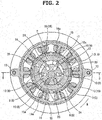
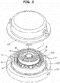
- FIG. 1 to FIG. 3 show a specific first embodiment for implementing an electric pump according to the present invention.
- FIG. 1 shows a sectional view taken along a line B-B of FIG. 2 as the entire sectional view of an electric pump 1
- FIG. 2 shows a sectional view taken along a ling A-A of FIG. 1
- FIG. 3 shows a perspective exploded view when a cover 4 of the electric pump 1 shown in FIG. 1 and FIG. 2 is removed.
- the electric pump 1 shown in FIG. 1 to FIG. 3 is one in which an electric motor 5 and a pump part 8 mentioned below are accommodated and concentrically disposed in a circular hosing 2 sealed by a hosing body 3 and the cover 4 such that their axial center direction positions match with each other.
- the entire shape of the electric pump 1 including the housing 2 is formed in a substantially flat shape.
- the electric motor 5 is configured of a annular stator 6 occupying the outer circumferential portion of the circular internal space of the hosing 2, and of a cylindrical rotor 7 occupying the inner space on the inner side of the stator 6.
- the rotor 7 also serves as the outer rotor of the pump part 8 which is mentioned below.
- the pump part 8 is configured of the rotor 7, an inner rotor 9 arranged eccentrically on the inner circumferential side of the rotor 7 such that a predetermined space is formed, a plurality of connecting plates 10 radially interposed between the rotor 7 and the inner rotor 9, and of a pair of side plates 11 and 12 mentioned below which are disposed on both sides of the inner rotor 9.
- the housing 2 accommodating the electric motor 5 and the pump part 8 is divided into two parts, one of which is the housing body 3 and the other of which is the cover 4 as a cover member. That is, it is formed as a half-split structure.
- the housing body 3 and the cover 4 abut on each other and fastened and fixed by two bolts 13.
- the stator 6 of the electric motor 5 has a well-known structure in which a plurality of tooth portions 14a are arranged at equal intervals and protrude from the inner circumferential side of a ring-shaped stator core 14 made of metal, and coils 15 are wound about these respective tooth portions 14a. Each of the coils 15 including the tooth portions 14a forms a magnetic pole.
- the rotor 7 of the electric motor 5 also serves as the outer rotor of the pump part 8.
- the present embodiment has a composite structure whose function is divided by using different material between the inner circumferential side and the outer circumferential side of the rotor 7, such that a function required as the rotor of the electric motor 5 and a function required as the outer rotor of the pump part 8 are sufficiently satisfied.
- the rotor 7 is configured of a cylindrical outer rotor 16 having a hollow shape on its inner circumferential side and a hollow cylindrical rotor body 17 fitted to the outer circumferential side of the outer rotor 16.
- the inner circumferential side outer rotor 16 is made of a single metal material.
- the outer circumferential side rotor body 17 is formed by a steel sheet laminated body such as an electromagnetic steel sheet.
- the rotor body 17 is formed, in its circumferential direction, with a plurality of slot portions 18 (the number of the slot portions 18 is the same as that of the coils 15 on the stator 6 side) formed at equal intervals and penetrating in the axial center direction, and permanent magnets 19 are inserted into these respective slot portions 18 and fixed by adhesives.
- a fine gap corresponding to a so-called air gap is formed between each of the tooth portions 14a on the stator 6 side and the rotor body 17.
- the outer rotor 16 forming the rotor 7 with the rotor body 17 is formed, at its outer circumferential edge portion, with a rim portion 20 having a step whose length (a length in the axial center direction) is longer than that of the rotor body 17, and the rim portion 20 protrudes in the axial center direction from both ends of the rotor body 17.
- End plates 21 made of a non-magnetic material such as an aluminum plate are stacked on both end surfaces of the rotor body 17 and cover permanent magnets 19, and the rotor body 17 is press-fitted into the small diameter portion of the rim portion 20 of the outer rotor 16, and then is integrally fixed to the outer circumference of the outer rotor 16 by press-fitting a stopper ring 22. With this, at least the rotor body 17 forms the permanent magnet embedded type electric motor 5 with the stator 6.
- each of the end plates 21 made of a non-magnetic material is provided to suppress the lowering of output of each of the permanent magnets 19 embedded to the rotor body 17 caused by the leakage of magnetic flux.
- the entire rotor 7 configured of the outer rotor 16 and the rotor body 17 is formed by a steel sheet laminated body or made of other metal materials as one body, as mentioned above, it also serves as the rotor 7 of the electric motor 5 and the outer rotor 16 of the pump part 8.
- the cylindrical inner rotor 9 whose diameter is smaller than the inner diameter of the outer rotor 16 is disposed at a position eccentric from the axial center position of the outer rotor 16 so as to be inscribed in the inner circumferential surface of the outer rotor 16, and the space between the outer rotor 16 and the inner rotor 9 becomes a pump chamber P.
- a plurality of slot portions 23 having square groove shapes are opened on the outer circumferential surface of the inner rotor 9.
- the slot portions 23 extend radially and are radially arranged on the outer circumferential surface of the inner rotor 9 at equal intervals.
- the connecting plates 10 as plate members, each of which is formed in a deformed vane shape, are slidably inserted into and supported on the respective slot portions 23. That is, the connecting plates 10 are inserted into and supported on the respective slot portions 23 so as to protrude from and retract to the respective slot portions 23.
- Each of the connecting plates 10 is formed generally in a key-hole shape in cross section, and the base portion on an inner rotor 9 side of each of the slot portions 23 is thick and the distal end portion on an outer rotor 16 side of each of the slot portions 23 is formed as a cylindrical swing shaft portion 10a which is thinner than the base portion.
- each of the connecting plates 10 can swing with the respective swing shaft portions 10a as a rotation center, and the separation of each of the connecting portions 10 from the outer rotor 16 is prevented.
- each of the connecting plates 10 is set so as to protrude from and retract to a corresponding one of the slot portions 23 to the extent that the base portions do not slip out from the respective slot portions 23 of the inner rotor 9.
- the plurality of the connecting plates 10 are disposed between the outer rotor 16 and the inner rotor 9 so as to be crosslinked, and the pump chamber P formed between the outer rotor 16 and the inner rotor 9 is divided into a plurality of regions.
- a support protruding portion 3a having a relatively large diameter is formed in the middle part of the inner bottom surface of the housing body 3, except a space R1 facing the stator 6.
- a ring-shaped support protruding portion 4a is formed in the middle part of the inner bottom surface of the cover 4, except a space R2 facing the stator 6.
- a ball bearing 26 as a bearing is interposed in the space between the support protruding portion 4a on a cover 4 side and one end portion in the longitudinal direction of the rim portion 20 in the outer rotor 16, and a ball bearing 25 as a bearing is interposed in the space between the support protruding potion 3a on a housing body 3 side and the other end portion in the longitudinal direction of the rim portion 20.
- the outer rotor 16 that is, the rotor 7 is rotatably axially supported at both ends by the support protruding portion 3a on the housing body 3 side and the support protruding portion 4a on the cover 4 side.
- the side plate 11 on the housing body 3 side and the side plate 12 on the cover 4 side are disposed on both side surfaces of the inner rotor 9 so as to extend to a part of the outer rotor 16.
- the pump chamber P formed between the outer rotor 16 and the inner rotor 9 is also isolated in the axial center direction.
- the positive displacement type pump part 8 is configured of the outer rotor 16, the inner rotor 9, the connecting plates 10 and the both side plates 11 and 12.
- a stepped shaft-like shaft member 27 which penetrates through the inner rotor 9 and the side plate 11 on the housing body 3 side is disposed extending from the support protruding portion 3a on the housing body 3 side to the side plate 12 on the cover 4 side.
- This shaft member 27 rotatably supports the inner rotor 9 in the middle part in the longitudinal direction thereof.
- one end portion in the longitudinal direction of the shaft member 27 is fitted to and supported on the side plate 12 on the cover 4 side and the other end portion is fitted to and supported on the support protruding portion 3a on the housing body 3 side.
- a stepped boss portion 12a is formed on the back surface side of the side plate 12 on the cover 4 side.
- the boss portion 12a is fitted to and supported on the inner circumference of the ring-shaped support protruding portion 4a on the cover 4 side so as to slide in the axial center direction.
- a compression coil spring 28 is disposed as an elastic member on the outer circumference at the small diameter part of the boss portion 12a. This compression coil spring 28 is interposed between the boss portion 12a and the inner bottom surface of the support protruding portion 4a on the cover 4 side in a compressed state.
- this structure is a state in which the inner rotor 9, the outer rotor 16 and the side plates 11 and 12 disposed on the both sides of each of the inner rotor 9 and the outer rotor 16 so as to sandwich the inner rotor 9 and the outer rotor 16 are pressed against each other so as to be brought into close contact with each other. Consequently, close contact property and also sealing performance between the inner rotor 9, the outer rotor 16 and the both side plates 11 and 12 are secured.
- a suction port 29 and a discharge port 30 communicating to the pump chamber P are formed on the side plate 11 on the housing body 3 side.
- concave portions 31 and 32 are formed on the side plate 12 on the cover 4 side, concave portions 31 and 32 which respectively communicate with the suction port 29 and the discharge port 30 through the slot portions 23 on the inner rotor 9 side, slot portions 23 through which the respective connecting plates 10 are inserted.
- the suction port 29 and the discharge port 30 are respectively connected to a suction port and a discharge port (not shown) formed on the housing body 3.
- annular grooves 33 are formed on the respective inner side surfaces of the both side plates 11 and 12 which face the inner rotor 9 and annular grooves 34 are formed on the respective inner side surfaces of the both side plates 11 and 12 which face the inner rotor 9, so as to surround the shaft member 27.
- Side clearances as fine gaps are provided between the side surface of the inner rotor 9 and each part corresponding to the suction port 29, the discharge port 30 and the annular groove 33 formed on the side plate 11 and between the side surface of the inner rotor 9 and each part corresponding to the concave portions 31 and 32 and the annular groove 34 formed on the side plate 12.
- the electric pump 1 is an oil pump
- the annular grooves 33 and 34 formed on each of the both side plates 11 and 12 serve as spaces to store a part of oil to be pressure-fed as lubrication oil used at sliding parts between the side plate 11 and the inner rotor 9 and between the slide plate 12 and the inner rotor 9.
- the suction port 29 or the discharge port 30 formed on the side plate 11 on the housing body 3 side faces the ball bearing 25 shown in, for example, FIG. 1 , such that a part of the oil to be pressure-fed fills the both ball bearings 25 and 26 and the spaces R1 and R2 respectively formed on the housing body 3 side and the cover 4 side, including stator 6.
- the stator 6 and the rotor 7, including each of the coils 15 are filled with the oil to be pressure-fed, and consequently, the both ball bearings 25 and 26 are lubricated and cooling of the stator 6 and the rotor 7 are performed by the oil.
- the rotation of the rotor 7 mentioned above is transmitted to the inner side inner rotor 9 through the plurality of the connecting plates 10 existing between the outer rotor 16 and the inner rotor 9.
- the inner roto 9 rotates with the outer rotor 16 integrally.
- the inner rotor 9 since the axial center of the inner rotor 9 is eccentric to the axial center of the rotor 7, the inner rotor 9 itself rotates about the shaft member 27 as a rotation center, while being inscribed in the inner circumferential surface of the outer rotor 16, continuously changing its inscribed position.
- the connecting plates 10 inserted into the respective slot portions 23 of the inner rotor 9 repeatedly protrude from and retract to the respective slot portion 23 while oscillating about the corresponding swing shaft portions 10a as centers, with the rotational motion of the inner rotor 9 about the shaft member 27 as a rotation center while being inscribed in the inner circumferential surface of the outer rotor 16, and by the protrusion and retraction of each of the connecting plates 10 in the pump chamber P, a function as a so-called positive displacement type pump is exhibited.
- the side plate 12 on the cover 4 side is pressed to the side surfaces of the outer rotor 16 and the inner rotor 9 by the compression coil spring 28, and the outer rotor 16 and the inner rotor 9 receiving the pressing force of the side plate 12 are pressed to the side plate 11 on the housing body 3 side.
- the both side plates 11 and 12 disposed on the both side surfaces of the outer rotor 16 and the both side surfaces of the inner rotor 9 sandwich the outer rotor 16 and the inner rotor 9 therebetween by the elastic force of the compression coil spring 28.
- the side clearance is set to a part of the close-contact surface of each of the side plates 11 and 12, each of which is brought into close contact with the outer rotor 16 and the inner rotor 9, and oil lubrication is performed through the oil existing at these parts. Consequently, it is possible to suppress partial abrasion at the parts and to reduce frictional resistance, and thereby the rotation of the outer rotor 16 and the inner rotor 9 is performed more stably.
- the rotor 7 is not rotatably supported at a part close to a rotation center position, but is rotatably supported at the both ends at the outer side part in the radial direction by the ball bearings 25 and 26. Consequently, the rotation of the rotor 7 is also performed stably, and durability of the electric pump 1 including the ball bearings 25 and 26 is also improved.
- the entire housing 2 configured of the housing body 3 and the cover 4 so as to be thick, or so as to have high rigidity, and, as the electric pump 1 in which the electric motor 5 and the pump part 8 are integrated, as shown in FIG. 1 , the entire housing 2 can be formed in a flat shape and can be compact.
- the type of the pump part 8 is not limited to this, and other pump part types such as a trochoid type may be used.
- the rotor 7 is configured of the outer rotor 16 and the rotor body 17, such that a function required for the electric motor 5 and a function required for the pump part 8 are sufficiently satisfied.
- the rotor 7 may have a structure in which the outer rotor 16 and the rotor body 17 are completely integrated by using the same material as needed.
Landscapes
- Engineering & Computer Science (AREA)
- Mechanical Engineering (AREA)
- General Engineering & Computer Science (AREA)
- Rotary Pumps (AREA)
- Details And Applications Of Rotary Liquid Pumps (AREA)
Applications Claiming Priority (1)
| Application Number | Priority Date | Filing Date | Title |
|---|---|---|---|
| JP2016240780A JP2018096269A (ja) | 2016-12-13 | 2016-12-13 | 電動ポンプ |
Publications (1)
| Publication Number | Publication Date |
|---|---|
| EP3336357A1 true EP3336357A1 (fr) | 2018-06-20 |
Family
ID=60484173
Family Applications (1)
| Application Number | Title | Priority Date | Filing Date |
|---|---|---|---|
| EP17203992.7A Withdrawn EP3336357A1 (fr) | 2016-12-13 | 2017-11-28 | Pompe électrique |
Country Status (4)
| Country | Link |
|---|---|
| US (1) | US20180163723A1 (fr) |
| EP (1) | EP3336357A1 (fr) |
| JP (1) | JP2018096269A (fr) |
| CN (1) | CN108612652A (fr) |
Cited By (1)
| Publication number | Priority date | Publication date | Assignee | Title |
|---|---|---|---|---|
| WO2024245508A1 (fr) * | 2023-06-01 | 2024-12-05 | Hanon Systems Efp Deutschland Gmbh | Pompe à rotors dentés |
Families Citing this family (3)
| Publication number | Priority date | Publication date | Assignee | Title |
|---|---|---|---|---|
| KR20230007094A (ko) | 2021-07-05 | 2023-01-12 | 엘지이노텍 주식회사 | 펌프 |
| CN116576103B (zh) * | 2023-05-22 | 2025-11-04 | 上海福慧特泵业制造有限公司 | 一种全封闭平衡型制冷剂泵 |
| CN119641622B (zh) * | 2024-12-13 | 2025-11-11 | 青岛大学 | 一种刮板式永磁同步电磁泵 |
Citations (6)
| Publication number | Priority date | Publication date | Assignee | Title |
|---|---|---|---|---|
| US20050031465A1 (en) * | 2003-08-07 | 2005-02-10 | Dreiman Nelik I. | Compact rotary compressor |
| JP2011074843A (ja) | 2009-09-30 | 2011-04-14 | Asmo Co Ltd | 電動ポンプ |
| JP2012041867A (ja) | 2010-08-19 | 2012-03-01 | Toyo Advanced Technologies Co Ltd | 電動ポンプ |
| JP2012067735A (ja) | 2010-09-27 | 2012-04-05 | Mahle Filter Systems Japan Corp | 電動ポンプ |
| EP2698539A2 (fr) * | 2012-08-14 | 2014-02-19 | MAHLE Filter Systems Japan Corporation | Pompe à double entraînement électrique |
| DE112014006053T5 (de) * | 2013-12-25 | 2016-09-29 | Denso Corporation | Zylinderrotationskompressor |
Family Cites Families (14)
| Publication number | Priority date | Publication date | Assignee | Title |
|---|---|---|---|---|
| US2405061A (en) * | 1942-12-02 | 1946-07-30 | Eaton Mfg Co | Pump structure |
| US2871793A (en) * | 1956-06-29 | 1959-02-03 | Robbins & Myers | Electric motor and pump combination |
| US5862664A (en) * | 1995-11-16 | 1999-01-26 | Kanzaki Kokyukoki Mfg. Co., Ltd. | Charging pump for a hydrostatic transmission |
| JP2003129966A (ja) * | 2001-10-24 | 2003-05-08 | Aisin Seiki Co Ltd | 電動オイルポンプ |
| JP2005207245A (ja) * | 2004-01-20 | 2005-08-04 | Koyo Seiko Co Ltd | 電動ポンプユニット |
| US20060039815A1 (en) * | 2004-08-18 | 2006-02-23 | Allan Chertok | Fluid displacement pump |
| JP4084351B2 (ja) * | 2004-12-24 | 2008-04-30 | 株式会社日立製作所 | モータ一体型内接歯車式ポンプ及び電子機器 |
| US7641457B2 (en) * | 2006-03-28 | 2010-01-05 | Jtekt Corporation | Internal gear pump |
| JP5141956B2 (ja) * | 2007-12-25 | 2013-02-13 | アイシン精機株式会社 | 電動ポンプ |
| JP5126588B2 (ja) * | 2008-01-08 | 2013-01-23 | アイシン精機株式会社 | 電動ポンプ |
| DE102010041550A1 (de) * | 2010-09-28 | 2012-03-29 | Mahle International Gmbh | Pendelschieberzellenpumpe |
| JP5635352B2 (ja) * | 2010-09-30 | 2014-12-03 | Ntn株式会社 | 複合滑り軸受 |
| CN102338082A (zh) * | 2011-07-19 | 2012-02-01 | 大连液压件有限公司 | 三体外泄式转向助力泵 |
| CN103541893B (zh) * | 2013-11-04 | 2016-03-16 | 湖南南方宇航高精传动有限公司 | 一种内啮合轴头摆线齿轮泵 |
-
2016
- 2016-12-13 JP JP2016240780A patent/JP2018096269A/ja active Pending
-
2017
- 2017-11-20 CN CN201711158983.1A patent/CN108612652A/zh active Pending
- 2017-11-27 US US15/822,561 patent/US20180163723A1/en not_active Abandoned
- 2017-11-28 EP EP17203992.7A patent/EP3336357A1/fr not_active Withdrawn
Patent Citations (6)
| Publication number | Priority date | Publication date | Assignee | Title |
|---|---|---|---|---|
| US20050031465A1 (en) * | 2003-08-07 | 2005-02-10 | Dreiman Nelik I. | Compact rotary compressor |
| JP2011074843A (ja) | 2009-09-30 | 2011-04-14 | Asmo Co Ltd | 電動ポンプ |
| JP2012041867A (ja) | 2010-08-19 | 2012-03-01 | Toyo Advanced Technologies Co Ltd | 電動ポンプ |
| JP2012067735A (ja) | 2010-09-27 | 2012-04-05 | Mahle Filter Systems Japan Corp | 電動ポンプ |
| EP2698539A2 (fr) * | 2012-08-14 | 2014-02-19 | MAHLE Filter Systems Japan Corporation | Pompe à double entraînement électrique |
| DE112014006053T5 (de) * | 2013-12-25 | 2016-09-29 | Denso Corporation | Zylinderrotationskompressor |
Cited By (1)
| Publication number | Priority date | Publication date | Assignee | Title |
|---|---|---|---|---|
| WO2024245508A1 (fr) * | 2023-06-01 | 2024-12-05 | Hanon Systems Efp Deutschland Gmbh | Pompe à rotors dentés |
Also Published As
| Publication number | Publication date |
|---|---|
| CN108612652A (zh) | 2018-10-02 |
| US20180163723A1 (en) | 2018-06-14 |
| JP2018096269A (ja) | 2018-06-21 |
Similar Documents
| Publication | Publication Date | Title |
|---|---|---|
| US5811902A (en) | Support structure for electric motor used for operating pump | |
| US20180163723A1 (en) | Electric pump | |
| EP1566545B1 (fr) | Pompe électrique à engrenage intérieur | |
| JP4475391B2 (ja) | 電動ポンプユニット | |
| CN102333955A (zh) | 集成电动叶片油泵 | |
| EP2075405B1 (fr) | Compresseur de type vanne | |
| EP1967733A2 (fr) | Pompe à ailettes à entraînement magnétique | |
| JP5391016B2 (ja) | 電動ポンプ | |
| JP6459740B2 (ja) | 流体ポンプ | |
| EP3144538B1 (fr) | Pompe électrique | |
| CN103370550B (zh) | 用于往复式制冷压缩机的轴承装置 | |
| US20160356271A1 (en) | Electric pump | |
| JP5601826B2 (ja) | 燃料ポンプ | |
| EP3196514B1 (fr) | Pompe avec joint d'étanchéité mécanique | |
| US4492515A (en) | Pump apparatus | |
| CN117940670B (zh) | 涡旋式压缩机 | |
| JP6151324B2 (ja) | 密閉型電動圧縮機 | |
| JPH0286976A (ja) | スクロール流体機械 | |
| US12163517B2 (en) | Scroll compressor with Oldham ring and keys in orbiting scroll | |
| CN205533240U (zh) | 旋转式机械 | |
| JP4300529B2 (ja) | ベーン式ポンプ | |
| JP3239642U (ja) | 回転モータの構造 | |
| JP2023161169A (ja) | 回転電機及びそのローター | |
| JP6235318B2 (ja) | 密閉型圧縮機 | |
| JP2026031007A (ja) | モータ |
Legal Events
| Date | Code | Title | Description |
|---|---|---|---|
| PUAI | Public reference made under article 153(3) epc to a published international application that has entered the european phase |
Free format text: ORIGINAL CODE: 0009012 |
|
| AK | Designated contracting states |
Kind code of ref document: A1 Designated state(s): AL AT BE BG CH CY CZ DE DK EE ES FI FR GB GR HR HU IE IS IT LI LT LU LV MC MK MT NL NO PL PT RO RS SE SI SK SM TR |
|
| AX | Request for extension of the european patent |
Extension state: BA ME |
|
| 17P | Request for examination filed |
Effective date: 20180907 |
|
| RBV | Designated contracting states (corrected) |
Designated state(s): AL AT BE BG CH CY CZ DE DK EE ES FI FR GB GR HR HU IE IS IT LI LT LU LV MC MK MT NL NO PL PT RO RS SE SI SK SM TR |
|
| STAA | Information on the status of an ep patent application or granted ep patent |
Free format text: STATUS: THE APPLICATION HAS BEEN WITHDRAWN |
|
| 18W | Application withdrawn |
Effective date: 20200720 |