EP3336370B1 - Ensembles à rouleaux pour culbuteur et pour fourche de cardan - Google Patents
Ensembles à rouleaux pour culbuteur et pour fourche de cardan Download PDFInfo
- Publication number
- EP3336370B1 EP3336370B1 EP17204448.9A EP17204448A EP3336370B1 EP 3336370 B1 EP3336370 B1 EP 3336370B1 EP 17204448 A EP17204448 A EP 17204448A EP 3336370 B1 EP3336370 B1 EP 3336370B1
- Authority
- EP
- European Patent Office
- Prior art keywords
- roller assembly
- inner member
- roller
- radially
- rollers
- Prior art date
- Legal status (The legal status is an assumption and is not a legal conclusion. Google has not performed a legal analysis and makes no representation as to the accuracy of the status listed.)
- Not-in-force
Links
Images


Classifications
-
- F—MECHANICAL ENGINEERING; LIGHTING; HEATING; WEAPONS; BLASTING
- F16—ENGINEERING ELEMENTS AND UNITS; GENERAL MEASURES FOR PRODUCING AND MAINTAINING EFFECTIVE FUNCTIONING OF MACHINES OR INSTALLATIONS; THERMAL INSULATION IN GENERAL
- F16C—SHAFTS; FLEXIBLE SHAFTS; ELEMENTS OR CRANKSHAFT MECHANISMS; ROTARY BODIES OTHER THAN GEARING ELEMENTS; BEARINGS
- F16C13/00—Rolls, drums, discs, or the like; Bearings or mountings therefor
- F16C13/006—Guiding rollers, wheels or the like, formed by or on the outer element of a single bearing or bearing unit, e.g. two adjacent bearings, whose ratio of length to diameter is generally less than one
-
- F—MECHANICAL ENGINEERING; LIGHTING; HEATING; WEAPONS; BLASTING
- F16—ENGINEERING ELEMENTS AND UNITS; GENERAL MEASURES FOR PRODUCING AND MAINTAINING EFFECTIVE FUNCTIONING OF MACHINES OR INSTALLATIONS; THERMAL INSULATION IN GENERAL
- F16C—SHAFTS; FLEXIBLE SHAFTS; ELEMENTS OR CRANKSHAFT MECHANISMS; ROTARY BODIES OTHER THAN GEARING ELEMENTS; BEARINGS
- F16C19/00—Bearings with rolling contact, for exclusively rotary movement
- F16C19/22—Bearings with rolling contact, for exclusively rotary movement with bearing rollers essentially of the same size in one or more circular rows, e.g. needle bearings
- F16C19/24—Bearings with rolling contact, for exclusively rotary movement with bearing rollers essentially of the same size in one or more circular rows, e.g. needle bearings for radial load mainly
- F16C19/28—Bearings with rolling contact, for exclusively rotary movement with bearing rollers essentially of the same size in one or more circular rows, e.g. needle bearings for radial load mainly with two or more rows of rollers
-
- F—MECHANICAL ENGINEERING; LIGHTING; HEATING; WEAPONS; BLASTING
- F16—ENGINEERING ELEMENTS AND UNITS; GENERAL MEASURES FOR PRODUCING AND MAINTAINING EFFECTIVE FUNCTIONING OF MACHINES OR INSTALLATIONS; THERMAL INSULATION IN GENERAL
- F16C—SHAFTS; FLEXIBLE SHAFTS; ELEMENTS OR CRANKSHAFT MECHANISMS; ROTARY BODIES OTHER THAN GEARING ELEMENTS; BEARINGS
- F16C33/00—Parts of bearings; Special methods for making bearings or parts thereof
- F16C33/72—Sealings
- F16C33/76—Sealings of ball or roller bearings
- F16C33/78—Sealings of ball or roller bearings with a diaphragm, disc, or ring, with or without resilient members
- F16C33/7816—Details of the sealing or parts thereof, e.g. geometry, material
- F16C33/782—Details of the sealing or parts thereof, e.g. geometry, material of the sealing region
-
- F—MECHANICAL ENGINEERING; LIGHTING; HEATING; WEAPONS; BLASTING
- F16—ENGINEERING ELEMENTS AND UNITS; GENERAL MEASURES FOR PRODUCING AND MAINTAINING EFFECTIVE FUNCTIONING OF MACHINES OR INSTALLATIONS; THERMAL INSULATION IN GENERAL
- F16C—SHAFTS; FLEXIBLE SHAFTS; ELEMENTS OR CRANKSHAFT MECHANISMS; ROTARY BODIES OTHER THAN GEARING ELEMENTS; BEARINGS
- F16C33/00—Parts of bearings; Special methods for making bearings or parts thereof
- F16C33/72—Sealings
- F16C33/76—Sealings of ball or roller bearings
- F16C33/78—Sealings of ball or roller bearings with a diaphragm, disc, or ring, with or without resilient members
- F16C33/7816—Details of the sealing or parts thereof, e.g. geometry, material
- F16C33/783—Details of the sealing or parts thereof, e.g. geometry, material of the mounting region
-
- F—MECHANICAL ENGINEERING; LIGHTING; HEATING; WEAPONS; BLASTING
- F16—ENGINEERING ELEMENTS AND UNITS; GENERAL MEASURES FOR PRODUCING AND MAINTAINING EFFECTIVE FUNCTIONING OF MACHINES OR INSTALLATIONS; THERMAL INSULATION IN GENERAL
- F16C—SHAFTS; FLEXIBLE SHAFTS; ELEMENTS OR CRANKSHAFT MECHANISMS; ROTARY BODIES OTHER THAN GEARING ELEMENTS; BEARINGS
- F16C33/00—Parts of bearings; Special methods for making bearings or parts thereof
- F16C33/72—Sealings
- F16C33/76—Sealings of ball or roller bearings
- F16C33/78—Sealings of ball or roller bearings with a diaphragm, disc, or ring, with or without resilient members
- F16C33/784—Sealings of ball or roller bearings with a diaphragm, disc, or ring, with or without resilient members mounted to a groove in the inner surface of the outer race and extending toward the inner race
- F16C33/7843—Sealings of ball or roller bearings with a diaphragm, disc, or ring, with or without resilient members mounted to a groove in the inner surface of the outer race and extending toward the inner race with a single annular sealing disc
- F16C33/7846—Sealings of ball or roller bearings with a diaphragm, disc, or ring, with or without resilient members mounted to a groove in the inner surface of the outer race and extending toward the inner race with a single annular sealing disc with a gap between the annular disc and the inner race
-
- F—MECHANICAL ENGINEERING; LIGHTING; HEATING; WEAPONS; BLASTING
- F16—ENGINEERING ELEMENTS AND UNITS; GENERAL MEASURES FOR PRODUCING AND MAINTAINING EFFECTIVE FUNCTIONING OF MACHINES OR INSTALLATIONS; THERMAL INSULATION IN GENERAL
- F16C—SHAFTS; FLEXIBLE SHAFTS; ELEMENTS OR CRANKSHAFT MECHANISMS; ROTARY BODIES OTHER THAN GEARING ELEMENTS; BEARINGS
- F16C33/00—Parts of bearings; Special methods for making bearings or parts thereof
- F16C33/72—Sealings
- F16C33/76—Sealings of ball or roller bearings
- F16C33/78—Sealings of ball or roller bearings with a diaphragm, disc, or ring, with or without resilient members
- F16C33/784—Sealings of ball or roller bearings with a diaphragm, disc, or ring, with or without resilient members mounted to a groove in the inner surface of the outer race and extending toward the inner race
- F16C33/7843—Sealings of ball or roller bearings with a diaphragm, disc, or ring, with or without resilient members mounted to a groove in the inner surface of the outer race and extending toward the inner race with a single annular sealing disc
- F16C33/7853—Sealings of ball or roller bearings with a diaphragm, disc, or ring, with or without resilient members mounted to a groove in the inner surface of the outer race and extending toward the inner race with a single annular sealing disc with one or more sealing lips to contact the inner race
-
- F—MECHANICAL ENGINEERING; LIGHTING; HEATING; WEAPONS; BLASTING
- F16—ENGINEERING ELEMENTS AND UNITS; GENERAL MEASURES FOR PRODUCING AND MAINTAINING EFFECTIVE FUNCTIONING OF MACHINES OR INSTALLATIONS; THERMAL INSULATION IN GENERAL
- F16C—SHAFTS; FLEXIBLE SHAFTS; ELEMENTS OR CRANKSHAFT MECHANISMS; ROTARY BODIES OTHER THAN GEARING ELEMENTS; BEARINGS
- F16C33/00—Parts of bearings; Special methods for making bearings or parts thereof
- F16C33/72—Sealings
- F16C33/76—Sealings of ball or roller bearings
- F16C33/78—Sealings of ball or roller bearings with a diaphragm, disc, or ring, with or without resilient members
- F16C33/784—Sealings of ball or roller bearings with a diaphragm, disc, or ring, with or without resilient members mounted to a groove in the inner surface of the outer race and extending toward the inner race
- F16C33/7843—Sealings of ball or roller bearings with a diaphragm, disc, or ring, with or without resilient members mounted to a groove in the inner surface of the outer race and extending toward the inner race with a single annular sealing disc
- F16C33/7853—Sealings of ball or roller bearings with a diaphragm, disc, or ring, with or without resilient members mounted to a groove in the inner surface of the outer race and extending toward the inner race with a single annular sealing disc with one or more sealing lips to contact the inner race
- F16C33/7856—Sealings of ball or roller bearings with a diaphragm, disc, or ring, with or without resilient members mounted to a groove in the inner surface of the outer race and extending toward the inner race with a single annular sealing disc with one or more sealing lips to contact the inner race with a single sealing lip
-
- F—MECHANICAL ENGINEERING; LIGHTING; HEATING; WEAPONS; BLASTING
- F16—ENGINEERING ELEMENTS AND UNITS; GENERAL MEASURES FOR PRODUCING AND MAINTAINING EFFECTIVE FUNCTIONING OF MACHINES OR INSTALLATIONS; THERMAL INSULATION IN GENERAL
- F16C—SHAFTS; FLEXIBLE SHAFTS; ELEMENTS OR CRANKSHAFT MECHANISMS; ROTARY BODIES OTHER THAN GEARING ELEMENTS; BEARINGS
- F16C33/00—Parts of bearings; Special methods for making bearings or parts thereof
- F16C33/72—Sealings
- F16C33/76—Sealings of ball or roller bearings
- F16C33/78—Sealings of ball or roller bearings with a diaphragm, disc, or ring, with or without resilient members
- F16C33/7816—Details of the sealing or parts thereof, e.g. geometry, material
- F16C33/782—Details of the sealing or parts thereof, e.g. geometry, material of the sealing region
- F16C33/7823—Details of the sealing or parts thereof, e.g. geometry, material of the sealing region of sealing lips
Definitions
- the present invention is directed to a cam follower assembly and a yoke roller assembly and more specifically to a cam follower assembly and a yoke roller assembly having an axial thrust retainer, a double row of rolling elements and a thin profile seal.
- Cam follower assemblies and yoke roller assemblies are used in many industrial manufacturing and conveying applications.
- the cam follower assemblies and the yoke roller assemblies each typically include an outer ring disposed around an inner ring with a plurality of rolling elements such as needle rollers disposed in a cavity therebetween.
- An annular seal is positioned on each axial end thereof, between the inner ring and the outer ring to keep debris from entering the cavity. The seals occupy an axial length of the cam follower assemblies and the yoke roller assemblies.
- the size of the cam follower assemblies and yoke roller assemblies are generally limited to a predetermined envelope.
- the axial length of cam follower assemblies may be limited a length of the cam that the cam follower rides on.
- the length of the yoke roller may be limited by the distance between yoke arms that the yoke roller is mounted on of on the length of the surface that the yoke roller engages.
- the length of the rolling elements is limited because of the axial length which the seals occupy.
- the outside diameter of the cam follower assemblies and the yoke roller assemblies may also be limited to a predetermined size.
- Cam follower assemblies and yoke roller assemblies are subject to high loads when used in various applications.
- the load capacity of the cam follower assemblies and yoke roller assemblies depends on the diameter and length of the rolling elements disposed therein.
- efforts to increase the load capacity of the cam follower assemblies and yoke roller assemblies have been plateaued because of the above described size limitations.
- US 2009/175567 A1 teaches a cam follower assembly having an outer race and an inner race with rollers located between the outer and inner races. The surfaces of the inner race are lapped and subsequently treated using a cold plastic deformation process, in which a high energy flow of abrasive material in a carrier medium is applied to the metal surfaces of the inner race.
- Document US 2009/175567 shows a roller assembly with sealing means as described in the preamble of appended independent claim 1.
- US 3,145,996 A discloses another sealing device for sealing the interstice between spaced confronting surfaces of a pair of relatively rotatable members particularly suitable for a bearing assembly. Document US 3,145,996 shows a sealing means in a roller assembly as described in the preamble of appended independent claim 12.
- roller assembly as described in appended claim 1 and a thin profile seal as described in appended claim 12. Further preferred features of the present invention are described in the appended dependent claims.
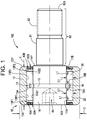
- a roller assembly for a cam follower 100 is generally designated by the reference number 10.
- the roller assembly 10 includes an outer ring 12 having an interior area 13.
- the interior area 13 is defined by an inner surface 13A extending an overall axial length L between a first axial end 13X and a second axial end 13Y of the outer ring 13.
- the inner surface 13A has a radially inward facing bearing surface 13B1, 13B2 extending between a first radially inwardly extending flange 13F1 and a second radially inwardly extending flange 13F2.
- the roller assembly 10 includes an inner member 14 extending into the interior area 13.
- the inner member 14 has a groove 15 formed therein and located between opposite axial ends 14X and 14Y of the inner member 14.
- a retaining ring 16 is positioned in the groove 15, as described herein.
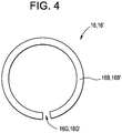
- the retaining ring 16 is a split ring having an annular body portion 16B and a gap 16G therein.
- the inner member 14 has a shaft 80 extending axially outward from the second axial end 14Y.
- the shaft 80 includes a shank portion 81 and a threaded portion 82.
- the threaded portion 82 extends axially inward from an axial end 80X of the shaft 80.
- the inner member 14 is manufactured from a carbon steel alloy.
- the exterior surfaces 14B1 and 14B2 of the inner member have a carburized case hardened case depth of 0.762 mm (0.03 inches) to 1.016 mm (0.04 inches).
- the exterior surfaces 14B1 and 14B2 have a surface hardness of 59 to 62 Rockwell C scale.
- the inner member and/or the shaft 80 have a core hardness of 30 to 35 Rockwell C scale.
- the roller assembly 10 includes a first row of a plurality of first rollers 20 positioned in the interior area 13 and in rolling engagement with the inner member 14 (i.e., an exterior surface 14B1 of the inner member 14) and the radially inward facing bearing surface 13B1.
- the first row of the plurality first rollers 20 is positioned axially between and engaging the retaining ring 16 (i.e., a first axial end 16A of the retaining ring 16) and the first radially extending flange 13F1.
- the roller assembly 10 includes a second row of a plurality of second rollers 30 positioned in the interior area 13 and in rolling engagement with the inner member 14 (i.e., an exterior surface 14B2 of the inner member 14) and the radially inward facing bearing surface 13B2.
- the second row of the plurality of second rollers 30 is positioned axially between and engaging the retaining ring 16 (i.e., a second axial end 16B of the retaining ring 16) and the second radially extending flange 13F2.
- first axial end 16A, second axial end 16B, the first radially inwardly extending flange 13F1 and the second radially inwardly extending flange 13F2 limit axial movement of the outer ring 12 relative to the inner member 14.
- each of the plurality of first rollers 20 and each of the plurality of second rollers 30 have a roller length L1.
- the ratio of roller length L to roller outside diameter D1 is less than 2.8 to provide increased load capacity compared to prior art roller assemblies.
- the roller length L1 is about 1.041 mm (0.410 inches) and the dynamic load capacity of the roller assembly 10 is about 5,960 kg (13,140 pounds).
- Each of the plurality of first rollers 20 and each of the plurality of second rollers 30 has an outside diameter D1 and the outer ring 12 has an outside diameter D.
- a ratio of the outside diameter D1 of the rollers 20, 30 to the second outside diameter D of the outer ring 12 ranges from 7.25 to 9.75.
- the inner surface 13A of the roller assembly 10 includes a first seal receiving pocket 40A formed between the first radially inwardly extending flange 13F1 and the first axial end 13X.
- a first annular seal 50A is positioned in and seated in the first seal receiving pocket 40A, as described herein.
- a portion (i.e., a radially innermost portion) of the first annular seal 50A slidingly and sealingly engages the inner member 14 (i.e., an exterior surface 17A of the inner member 14).
- the inner surface 13 of the roller assembly includes a second seal receiving pocket 40B formed between the second radially inwardly extending flange 13F2 and the second axial end 14Y.
- a second annular seal 50B is positioned in and seated in the second seal receiving pocket 40B.
- a portion (i.e., a radially innermost portion) of the first annular seal 50A slidingly and sealingly engages the inner member 14 (i.e., an exterior surface 17B of the inner member 14).
- a roller assembly for a yoke roller 200 is generally designated by the reference number 10'.
- the roller assembly 10' includes an outer ring 12' having an interior area 13'.
- the interior area 13' is defined by an inner surface 13A' extending an overall axial length L' between a first axial end 13X' and a second axial end 13Y' of the outer ring 12'.
- the inner surface 13A' has a radially inward facing bearing surface 13B1', 13B2' extending between a first radially inwardly extending flange 13F1' and a second radially inwardly extending flange 13F2'.
- the roller assembly 10' includes an inner member 14' extending into the interior area 13'.
- the inner member 14' has a groove 15' formed therein and located between opposite axial ends 14X and 14Y' of the inner member 14'.
- a retaining ring 16' is positioned in the groove 15', as described herein.
- the retaining ring 16' is a split ring having an annular body portion 16B' and a gap 16G' therein.
- the inner member 14' has a bore 90' extending therethrough.
- the bore 90' is defined by an inner surface 92' of the inner member 14'.
- the inner member 14' is manufactured from a carbon steel alloy.
- the exterior surfaces 14B1' and 14B2' of the inner member 14' have a carburized case hardened case depth of 0.762 mm (0.03 inches) to 1.016 mm (0.04 inches).
- the exterior surfaces 14B1' and 14B2' have a surface hardness of 59 to 62 Rockwell C scale.
- the inner member 14' has a core hardness of 30 to 35 Rockwell C scale.
- the roller assembly 10' includes a first row of a plurality of first rollers 20' positioned in the interior area 13' and in rolling engagement with the inner member 14' (i.e., an exterior surface 14B1' of the inner member 14') and the radially inward facing bearing surface 13B1'.
- the first row of the plurality first rollers 20' is positioned axially between and engaging the retaining ring 16' (i.e., a first axial end 16A' of the retaining ring 16') and the first radially extending flange 13F1'.
- the roller assembly 10' includes a second row of a plurality of second rollers 30' positioned in the interior area 13' and in rolling engagement with the inner member 14' (i.e., an exterior surface 14B2' of the inner member 14') and the radially inward facing bearing surface 13B2'.
- the second row of the plurality second rollers 30' is positioned axially between and engaging the retaining ring 16' (i.e., a second axial end 16B' of the retaining ring 16') and the second radially extending flange 13F2'.
- first axial end 16A', second axial end 16B', the first radially inwardly extending flange 13F1' and the second radially inwardly extending flange 13F2' limit axial movement of the outer ring 12' relative to the inner member 14'.
- each of the plurality of first rollers 20' and each of the plurality of second rollers 30' have a roller length L1'.
- the ratio of roller length to roller outside diameter is less than 2.8 to provide increased load capacity compared to prior art roller assemblies.
- the roller length L1' is about 1.041 mm (0.410 inches) and the dynamic load capacity of the roller assembly 10' is about 5,960 kg (13,140 pounds).
- Each of the plurality of first rollers 20' and each of the plurality of second rollers 30' has an outside diameter D1' and the outer ring 12 has an outside diameter D'.
- a ratio of the outside diameter D1' of the rollers 20', 30' to the second outside diameter D' of the outer ring 12' ranges from 7.25 to 9.75.
- the inner surface 13A' of the roller assembly 10' includes a first seal receiving pocket 40A' formed between the first radially inwardly extending flange 13F1' and the first axial end 13X'.
- a first annular seal 50A' is positioned in and seated in the first seal receiving pocket 40A', as described herein.
- a portion (i.e., a radially innermost portion) of the first annular seal 50A' slidingly and sealingly engages the inner member 14' (i.e., an exterior surface 17A' of the inner member 14').
- the inner surface 13' of the roller assembly 10' includes a second seal receiving pocket 40B' formed between the second radially inwardly extending flange 13F2' and the second axial end 14Y'.
- a second annular seal 50B' is positioned in and seated in the second seal receiving pocket 40B'.
- a portion (i.e., a radially innermost portion) of the first annular seal 50A' slidingly and sealingly engages the inner member 14' (i.e., an exterior surface 17B' of the inner member 14').
- the second annular seal 50B has an overall axial width W.
- the second annular seal 50B has a designed overall axial width W that consumes only 6% of the overall axial length L.
- the first annular seal 50A is configured similar to the second annular seal 50B and has the same thinness ratio as the second annular seal 50B. While the overall axial widths W of the first annular seal 50A and the second annular seal 50B are described as being equal, the present invention is not limited in this regard.
- a groove 12G is formed in the inner surface 13A of the outer ring 12 axially outward of the second radially inwardly extending flange 13F2 and a lip 12L extending radially inward proximate the second axial end 13Y of the outer ring 12.
- the second annular seal 50B is a thin profile seal that includes an elastomeric member 60 secured to an annular metallic ring 62.
- the annular metallic ring 62 has a mounting section 62M located circumferentially around a radially outermost portion of thereof.
- the metallic annular ring 62 has a first leg 63 extending axially away and radially inward from the mounting section 62M.
- the first leg 63 has a radially and axially inward facing sloped surface 63F.
- the metallic annular ring 62 has a second leg 64 extending radially inward from the first leg 63 and terminating at a distal end 64D.
- the mounting section 62M includes a flap 69 folded over a portion of the mounting section 62M and forming a bend 67 on a radially outermost portion of the mounting section 62M for seating in the groove 12G of the outer ring 12 of the roller assembly 10.
- the elastomeric member 60 has a base 60B secured to the radially and axially inward facing sloped surface 63F.
- the elastomeric member 60 has a flexible sealing leg 60L extending away from the base 60B and the radially and axially inward facing sloped surface 63F for sealing engagement with a portion of the exterior surface 17B of the inner member 14 of the roller assembly 10.
- the flexible sealing leg 60L terminating at a sealing engagement surface 60X thereof.
- the sealing engagement surface 60X extends radially inward from the distal end 64D of the second leg 64.
- the metallic annular ring 62 and the elastomeric member 60 have an overall axial width W configured to provide structural support and sealing.
- the first annular seal 50A and the second annular seal 50B each have an overall axial width is from about 1.905 mm (0.075 inches) to about 2.032 mm (0.080 inches).
- the designed thinness of the first and second annular seals 50A and 50B provides for extension of roller length, thereby yielding increased load capacity.
- the first annular seal 50A and the second annular seal 50B each have a designed axial width W which consumes no more than 6% of the overall length L of the outer ring.
- the first annular seals 50A, 50A' and the second annular seal 50B' are configured the same as the second annular seal 50B.
Landscapes
- Engineering & Computer Science (AREA)
- General Engineering & Computer Science (AREA)
- Mechanical Engineering (AREA)
- Mechanical Sealing (AREA)
- Rolling Contact Bearings (AREA)
Claims (15)
- Un ensemble de rouleaux (10) pour un galet (100) suiveur de came ou un galet (200) d'étrier, l'ensemble de rouleaux (10) comprenant :un anneau externe (12) ayant une zone intérieure (13), la zone intérieure (13) étant définie par une surface interne (13A) s'étendant sur une longueur axiale globale (L) entre une première extrémité axiale (13X) et une deuxième extrémité axiale (13Y) de l'anneau externe (12), la surface interne (13A) ayant une surface d'appui (13B1, 13B2) tournée radialement vers l'intérieur, s'étendant entre une première bride (13F1) s'étendant radialement vers l'intérieur et une deuxième bride (13F2) s'étendant radialement vers l'intérieur ;un élément interne (14) en une seule pièce s'étendant dans la zone intérieure (13), l'élément interne (14) ayant une gorge (15) formée à l'intérieur de lui entre une troisième extrémité axiale (14X) et une quatrième extrémité axiale (14Y) de l'élément interne (14), l'élément interne (14) s'étendant de façon continue entre la troisième extrémité axiale (14X) et la quatrième extrémité axiale (14Y) ;un anneau de retenue (16) positionnée dans la gorge (15) ;une première rangée d'une pluralité de premiers rouleaux (20) étant positionnée dans la zone intérieure (13) entre l'élément interne (14) et la surface d'appui (13B1, 13B2) tournée radialement vers l'intérieur, et en engagement de roulement avec ceux-ci, la première rangée de la pluralité de premiers rouleaux (20) étant positionnée entre l'anneau de retenue (16) et la première bride (13F1) s'étendant radialement vers l'intérieur et étant en engagement avec ceux-ci ;une deuxième rangée d'une pluralité de deuxièmes rouleaux (30) positionnée dans la zone intérieure (13) entre l'élément interne (14) et la surface d'appui (13B1, 13B2) tournée radialement vers l'intérieur, et en engagement de roulement avec ceux-ci, la deuxième rangée de la pluralité de deuxièmes rouleaux (30) étant positionnée entre l'anneau de retenue (16) et la deuxième bride (13F2) s'étendant radialement vers l'intérieur et étant en engagement avec ceux-ci ;la surface interne (13A) comprend en outre une première poche (40A) de réception de joint formée entre la première bride (13F1) s'étendant radialement vers l'intérieur et la première extrémité axiale (13X) ; etun premier joint annulaire (50A) étant positionné et logé dans la première poche (40A) de réception de joint, une partie du premier joint annulaire (50A) venant en engagement de manière coulissante et étanche avec l'élément interne (14),caractérisé en ce quele premier joint annulaire (50A) comprend :un anneau annulaire métallique (62) ayant une portion de montage (62M) située circonférentiellement autour d'une partie radialement la plus externe de celui-ci, l'anneau annulaire métallique (62) ayant une première branche (63) s'étendant axialement à l'opposé de la portion de montage (62M), et radialement vers l'intérieur, la première branche (63) ayant une surface inclinée (63F) tournée radialement et axialement vers l'intérieur, et l'anneau annulaire métallique (62) ayant une deuxième branche (64) s'étendant radialement vers l'intérieur à partir de la première branche (63) et se terminant à une extrémité distale (64D) ;un élément en élastomère (60) ayant une base (60B) fixée à la surface inclinée (63F) tournée radialement et axialement vers l'intérieur, l'élément en élastomère (60) ayant une branche d'étanchéité flexible (60L) s'étendant à l'opposé de la surface inclinée (63F) tournée radialement et axialement vers l'intérieur pour un engagement avec étanchéité avec l'élément interne (14) de l'ensemble de rouleaux (10), la branche d'étanchéité flexible (60L) se terminant au niveau d'une surface (60X) d'engagement avec étanchéité, la surface (60X) d'engagement avec étanchéité s'étendant radialement vers l'intérieur depuis l'extrémité distale (64D) de la deuxième branche (64);l'anneau annulaire métallique (62) et l'élément en élastomère (60) ayant une largeur axiale globale (W) configurée pour fournir un support structurel et une étanchéité, et chaque rouleau de la pluralité de premiers rouleaux (20) et chaque rouleau de la pluralité de deuxièmes rouleaux (30) ayant une longueur de rouleau (LI) et un diamètre extérieur de rouleau (D1);un rapport de la longueur du rouleau (LI) au diamètre extérieur du rouleau (D1) étant inférieur à 2,8 ;l'anneau externe (12) ayant un deuxième diamètre extérieur (D) ;un rapport du deuxième diamètre extérieur (D) au diamètre extérieur du rouleau (D1) allant de 7,25 à 9,75, le premier joint annulaire (50A) ayant une première largeur axiale globale, la première largeur axiale globale (W) n'étant pas supérieure à 6 % de la longueur axiale totale (L) de l'anneau externe (12).
- L'ensemble de rouleaux (10) selon la revendication 1, dans lequel la largeur axiale globale (W) va d'environ 1,905 mm (0,075 pouces) à environ 2,032 mm (0,080 pouces), pour faciliter l'extension de la longueur des rouleaux sans augmentation de la longueur globale de l'ensemble de rouleaux (10), produisant une capacité de charge accrue de l'ensemble de rouleaux (10).
- L'ensemble de rouleaux (10) selon la revendication 2, dans lequel la portion de montage (62M) comprend un rabat (69) replié sur une partie de la portion de montage (62M) et formant un coude (67) sur une partie radialement la plus extérieure de la portion de montage (62M) destinée à être logée dans une gorge (12G) de l'anneau externe (12) de l'ensemble de rouleaux (10).
- L'ensemble de rouleaux (10) selon la revendication 1, dans lequel :la surface interne (13A) comprend en outre une deuxième poche (40B) de réception de joint formée entre la deuxième bride (13F2) s'étendant radialement vers l'intérieur et la deuxième extrémité axiale (13Y) ; etun deuxième joint annulaire (50B) positionné et logé dans la deuxième poche (40B) de réception de joint, une partie du deuxième joint annulaire (50B) venant en engagement de manière coulissante et étanche avec l'élément interne (14), le deuxième joint annulaire (50B) ayant une première largeur axiale globale ; etle deuxième joint annulaire (50B) ayant une largeur axiale globale qui n'est pas supérieure à 6 % de la longueur globale de l'anneau externe (12).
- L'ensemble de rouleaux (10) selon la revendication 1, dans lequel le deuxième joint annulaire (50B) comprend un élément en élastomère (60) fixé à un anneau métallique annulaire (62).
- L'ensemble de rouleaux (10) selon la revendication 1, dans lequel l'élément interne (14) comprend un acier au carbone.
- L'ensemble de rouleaux (10) selon la revendication 1, dans lequel une partie de l'élément interne (14) a une profondeur de cémentation durcie par carburation allant de 0,762 à 1,016 mm (0,03 à 0,04 pouces).
- L'ensemble de rouleaux (10) selon la revendication 1, dans lequel l'élément interne (14) a une dureté de surface allant de 59 à 62 sur l'échelle Rockwell C et/ou l'élément interne (14) a une dureté à cœur de 30 à 35 sur l'échelle Rockwell C..
- L'ensemble de rouleaux (10) selon la revendication 1, dans lequel les extrémités axiales (16A, 16B) de l'anneau de retenue (16) viennent en engagement dans la gorge (15), la pluralité de premiers rouleaux (20) vient en engagement de manière coulissante avec l'une des extrémités axiales (16A, 16B) de l'anneau de retenue (16) et la pluralité de deuxièmes rouleaux (30) vient en engagement de manière coulissante avec une autre des extrémités axiales (16A, 16B) de l'anneau de retenue (16) afin de limiter le mouvement axial de l'anneau externe (12) par rapport à l'élément interne (14).
- L'ensemble de rouleaux (10) selon la revendication 1, dans lequel l'élément interne (14) comprend un arbre (80) qui s'étend vers l'extérieur à partir d'au moins une parmi la première extrémité axiale (13X) et la deuxième extrémité axiale (13Y).
- L'ensemble de rouleaux (10) selon la revendication 1, dans lequel l'élément interne (14) est un anneau annulaire.
- Un ensemble de rouleaux (10) et un ensemble formant joint à profil mince,
l'ensemble de rouleaux (10) comprenant : un anneau externe (12), un anneau interne (14) et des rouleaux (30) placés entre eux,
le joint à profil mince (50B) comprenant :un anneau annulaire métallique (62) ayant une portion de montage (62M) située circonférentiellement autour d'une partie radialement la plus externe de celui-ci, l'anneau annulaire métallique (62) ayant une première branche (63) s'étendant axialement à l'opposé de la portion de montage (62M) et radialement vers l'intérieur, la première branche (63) ayant une surface inclinée (63F) tournée radialement et axialement vers l'intérieur, et l'anneau annulaire métallique (62) ayant une deuxième branche (64) s'étendant radialement vers l'intérieur à partir de la première branche (63) et se terminant par une extrémité distale (64D) ;un élément en élastomère (60) ayant une base (60B) fixée à la surface inclinée (63F) tournée radialement et axialement vers l'intérieur,caractérisé en ce quel'élément en élastomère (60) a une branche d'étanchéité flexible (60L) s'étendant à l'opposé de la surface inclinée (63F) tournée radialement et axialement vers l'intérieur pour un engagement avec étanchéité avec un élément interne (14) de l'ensemble de rouleaux (10), la branche d'étanchéité flexible (60L) se terminant par une surface (60X) d'engagement avec étanchéité, la surface (60X) d'engagement avec étanchéité s'étendant radialement vers l'intérieur depuis l'extrémité distale (64D) de la deuxième branche (64) ;l'anneau annulaire métallique (62) et l'élément en élastomère (60) ayant une largeur axiale globale (W) configurée pour fournir un support structurel et une étanchéité, et le joint à profil mince ayant une première largeur axiale globale (W), la première largeur axiale globale (W) ne représentant pas plus de 6 % de la longueur axiale globale (L) d'un anneau externe (12) de l'ensemble de rouleaux (10). - L'ensemble de rouleaux et l'ensemble formant joint à profil mince selon la revendication 12, dans lesquels la largeur axiale globale va d'environ 1,905 mm (0,075 pouces) à environ 2,032 mm (0,080 pouces), pour faciliter l'extension de la longueur des rouleaux sans augmentation de la longueur globale de l'ensemble de rouleaux (10), produisant une capacité de charge accrue de l'ensemble de rouleaux (10).
- L'ensemble de rouleaux et l'ensemble formant joint à profil mince selon la revendication 13, dans lesquels la portion de montage (62M) comprend un rabat (69) replié sur une partie de la portion de montage (62M) et formant un coude (67) sur une partie radialement la plus externe de la portion de montage (62M) pour se loger dans une gorge (12G) d'un anneau externe (12) de l'ensemble de rouleaux (10).
- L'ensemble de rouleaux et l'ensemble formant joint à profil mince selon la revendication 12 monté dans un ensemble de rouleaux pour un ensemble formant galet suiveur de came ou d'étrier, l'ensemble de rouleaux comprenant :un anneau externe (12) ayant une zone intérieure (13), la zone intérieure (13) étant définie par une surface interne (13A) s'étendant sur une longueur axiale globale (L) entre une première extrémité axiale (13X) et une deuxième extrémité axiale (13Y) de l'anneau externe (12), la surface interne (13A) ayant une surface d'appui (13B1, 13B2) tournée radialement vers l'intérieur, s'étendant entre une première bride (13F1) s'étendant radialement vers l'intérieur et une deuxième bride (13F2) s'étendant radialement vers l'intérieur ;un élément interne (14) en une seule pièce s'étendant dans la zone intérieure (13), l'élément interne (14) ayant une gorge (15) formée à l'intérieur de lui entre une troisième extrémité axiale (14X) et une quatrième extrémité axiale (14Y) de l'élément interne (14), l'élément interne (14) s'étendant de façon continue entre la troisième extrémité axiale (14X) et la quatrième extrémité axiale (14Y) ;un anneau de retenue (16) positionné dans la gorge (15) ;une première rangée d'une pluralité de premiers rouleaux (20) positionnés dans la zone intérieure (13) entre l'élément interne (14) et la surface d'appui (13B1, 13B2) tournée radialement vers l'intérieur, et en engagement de roulement avec ceux-ci, la première rangée de la pluralité de premiers rouleaux (20) étant positionnée entre l'anneau de retenue (16) et la première bride (13F1) s'étendant radialement vers l'intérieur et étant en engagement avec ceux-ci ;une deuxième rangée d'une pluralité de deuxièmes rouleaux (30) positionnée dans la zone intérieure (13) entre l'élément interne (14) et la surface d'appui (13B1, 13B2) tournée radialement vers l'intérieur, et en engagement de roulement avec ceux-ci, la deuxième rangée de la pluralité de deuxièmes rouleaux (30) étant positionnée entre l'anneau de retenue (16) et la deuxième bride (13F2) s'étendant radialement vers l'intérieur, et étant en engagement avec ceux-ci ;la surface interne (13A) comprend en outre une première poche (40A) de réception de joint formée entre la première bride (13F1) s'étendant radialement vers l'intérieur et la première extrémité axiale (13X) ; etun premier joint annulaire (50A) positionné et logé dans la première poche (40A) de réception de joint, une partie du premier joint annulaire (50A) étant en engagement de manière coulissante et étanche avec l'élément interne (14) ; caractérisé en ce quechaque rouleau de la pluralité de premiers rouleaux (20) et chaque rouleau de la pluralité de deuxièmes rouleaux (30) ont une longueur de rouleau (L1) et un diamètre extérieur de rouleau (D1);un rapport de la longueur du rouleau (L1) au diamètre extérieur du rouleau (D1) est inférieur à 2,8 ;l'anneau externe (12) a un deuxième diamètre extérieur (D) ;un rapport du deuxième diamètre extérieur (D) au diamètre extérieur de rouleau (D1) est compris entre 7,25 et 9,75.
Applications Claiming Priority (1)
| Application Number | Priority Date | Filing Date | Title |
|---|---|---|---|
| US201662428099P | 2016-11-30 | 2016-11-30 |
Publications (2)
| Publication Number | Publication Date |
|---|---|
| EP3336370A1 EP3336370A1 (fr) | 2018-06-20 |
| EP3336370B1 true EP3336370B1 (fr) | 2021-09-08 |
Family
ID=60515224
Family Applications (1)
| Application Number | Title | Priority Date | Filing Date |
|---|---|---|---|
| EP17204448.9A Not-in-force EP3336370B1 (fr) | 2016-11-30 | 2017-11-29 | Ensembles à rouleaux pour culbuteur et pour fourche de cardan |
Country Status (1)
| Country | Link |
|---|---|
| EP (1) | EP3336370B1 (fr) |
Families Citing this family (2)
| Publication number | Priority date | Publication date | Assignee | Title |
|---|---|---|---|---|
| US10731743B2 (en) * | 2011-11-16 | 2020-08-04 | Roller Bearing Company Of America, Inc. | Cam follower and yoke roller assemblies |
| US10697493B2 (en) | 2018-02-15 | 2020-06-30 | Roller Bearing Company Of America, Inc. | Cam follower with multiple rows of independently operating bearings |
Family Cites Families (4)
| Publication number | Priority date | Publication date | Assignee | Title |
|---|---|---|---|---|
| US3145996A (en) * | 1962-03-06 | 1964-08-25 | Skf Ind Inc | Seal for bearing |
| US5531137A (en) * | 1988-07-12 | 1996-07-02 | Roller Bearing Company Of America | Cam follower assembly |
| US20090175567A1 (en) * | 2008-01-09 | 2009-07-09 | Roller Bearing Company Of America, Inc. | Cam followers for long life |
| US10731743B2 (en) * | 2011-11-16 | 2020-08-04 | Roller Bearing Company Of America, Inc. | Cam follower and yoke roller assemblies |
-
2017
- 2017-11-29 EP EP17204448.9A patent/EP3336370B1/fr not_active Not-in-force
Also Published As
| Publication number | Publication date |
|---|---|
| EP3336370A1 (fr) | 2018-06-20 |
Similar Documents
| Publication | Publication Date | Title |
|---|---|---|
| US10731743B2 (en) | Cam follower and yoke roller assemblies | |
| US6979131B1 (en) | Multiple-row radial bearing | |
| US20100189387A1 (en) | Rolling bearing | |
| US5074680A (en) | Angular contact bearings and method for making the same | |
| US10801546B2 (en) | Ball bearing cam follower for an adjustable aircraft seat | |
| US5470158A (en) | Seal for rolling bearings | |
| CN105317847B (zh) | 滚动轴承密封装置的嵌件、密封装置、万向节和轴承衬套 | |
| WO2013021887A1 (fr) | Roulement à rouleaux coniques et structure de montage pour celui-ci | |
| EP2085666B1 (fr) | Dispositif d'étanchéité et dispositif de palier à roulement | |
| US6921083B2 (en) | Sealing apparatus and a rolling bearing and a clutch apparatus provided therewith | |
| EP3336370B1 (fr) | Ensembles à rouleaux pour culbuteur et pour fourche de cardan | |
| CN109154326A (zh) | 轴承密封装置 | |
| US20140248016A1 (en) | Composite annular seal assembly for bearings | |
| US9926979B2 (en) | Sealing device for rolling bearing unit | |
| JP2015200393A (ja) | シールリング付転がり軸受 | |
| US10458468B2 (en) | Cam follower for high axial load applications | |
| JP5336317B2 (ja) | 円すいころ軸受 | |
| JP2015212567A (ja) | 転がり軸受 | |
| US7862241B2 (en) | Rolling bearing apparatus | |
| CN110337550B (zh) | 滚动轴承 | |
| JP6981143B2 (ja) | シール付き玉軸受 | |
| US11209050B1 (en) | Contamination-resistant bearing assembly | |
| EP3034899B1 (fr) | Joint d'étanchéité pour palier à rouleaux à alignement automatique | |
| JP2005069337A (ja) | シェル形ころ軸受 | |
| US6217224B1 (en) | Wear-resistant retainer for roller bearing |
Legal Events
| Date | Code | Title | Description |
|---|---|---|---|
| PUAI | Public reference made under article 153(3) epc to a published international application that has entered the european phase |
Free format text: ORIGINAL CODE: 0009012 |
|
| STAA | Information on the status of an ep patent application or granted ep patent |
Free format text: STATUS: THE APPLICATION HAS BEEN PUBLISHED |
|
| AK | Designated contracting states |
Kind code of ref document: A1 Designated state(s): AL AT BE BG CH CY CZ DE DK EE ES FI FR GB GR HR HU IE IS IT LI LT LU LV MC MK MT NL NO PL PT RO RS SE SI SK SM TR |
|
| AX | Request for extension of the european patent |
Extension state: BA ME |
|
| STAA | Information on the status of an ep patent application or granted ep patent |
Free format text: STATUS: REQUEST FOR EXAMINATION WAS MADE |
|
| 17P | Request for examination filed |
Effective date: 20181213 |
|
| RBV | Designated contracting states (corrected) |
Designated state(s): AL AT BE BG CH CY CZ DE DK EE ES FI FR GB GR HR HU IE IS IT LI LT LU LV MC MK MT NL NO PL PT RO RS SE SI SK SM TR |
|
| STAA | Information on the status of an ep patent application or granted ep patent |
Free format text: STATUS: EXAMINATION IS IN PROGRESS |
|
| 17Q | First examination report despatched |
Effective date: 20200430 |
|
| REG | Reference to a national code |
Ref country code: DE Ref legal event code: R079 Ref document number: 602017045610 Country of ref document: DE Free format text: PREVIOUS MAIN CLASS: F16C0013040000 Ipc: F16C0033780000 |
|
| RIC1 | Information provided on ipc code assigned before grant |
Ipc: F16C 33/78 20060101AFI20201120BHEP |
|
| GRAP | Despatch of communication of intention to grant a patent |
Free format text: ORIGINAL CODE: EPIDOSNIGR1 |
|
| STAA | Information on the status of an ep patent application or granted ep patent |
Free format text: STATUS: GRANT OF PATENT IS INTENDED |
|
| GRAJ | Information related to disapproval of communication of intention to grant by the applicant or resumption of examination proceedings by the epo deleted |
Free format text: ORIGINAL CODE: EPIDOSDIGR1 |
|
| GRAP | Despatch of communication of intention to grant a patent |
Free format text: ORIGINAL CODE: EPIDOSNIGR1 |
|
| INTG | Intention to grant announced |
Effective date: 20210125 |
|
| GRAJ | Information related to disapproval of communication of intention to grant by the applicant or resumption of examination proceedings by the epo deleted |
Free format text: ORIGINAL CODE: EPIDOSDIGR1 |
|
| GRAP | Despatch of communication of intention to grant a patent |
Free format text: ORIGINAL CODE: EPIDOSNIGR1 |
|
| GRAJ | Information related to disapproval of communication of intention to grant by the applicant or resumption of examination proceedings by the epo deleted |
Free format text: ORIGINAL CODE: EPIDOSDIGR1 |
|
| INTG | Intention to grant announced |
Effective date: 20210225 |
|
| GRAP | Despatch of communication of intention to grant a patent |
Free format text: ORIGINAL CODE: EPIDOSNIGR1 |
|
| STAA | Information on the status of an ep patent application or granted ep patent |
Free format text: STATUS: EXAMINATION IS IN PROGRESS |
|
| GRAJ | Information related to disapproval of communication of intention to grant by the applicant or resumption of examination proceedings by the epo deleted |
Free format text: ORIGINAL CODE: EPIDOSDIGR1 |
|
| INTG | Intention to grant announced |
Effective date: 20210315 |
|
| INTG | Intention to grant announced |
Effective date: 20210318 |
|
| GRAP | Despatch of communication of intention to grant a patent |
Free format text: ORIGINAL CODE: EPIDOSNIGR1 |
|
| INTG | Intention to grant announced |
Effective date: 20210324 |
|
| STAA | Information on the status of an ep patent application or granted ep patent |
Free format text: STATUS: GRANT OF PATENT IS INTENDED |
|
| INTC | Intention to grant announced (deleted) | ||
| INTG | Intention to grant announced |
Effective date: 20210422 |
|
| GRAS | Grant fee paid |
Free format text: ORIGINAL CODE: EPIDOSNIGR3 |
|
| GRAA | (expected) grant |
Free format text: ORIGINAL CODE: 0009210 |
|
| STAA | Information on the status of an ep patent application or granted ep patent |
Free format text: STATUS: THE PATENT HAS BEEN GRANTED |
|
| AK | Designated contracting states |
Kind code of ref document: B1 Designated state(s): AL AT BE BG CH CY CZ DE DK EE ES FI FR GB GR HR HU IE IS IT LI LT LU LV MC MK MT NL NO PL PT RO RS SE SI SK SM TR |
|
| REG | Reference to a national code |
Ref country code: GB Ref legal event code: FG4D |
|
| REG | Reference to a national code |
Ref country code: AT Ref legal event code: REF Ref document number: 1428858 Country of ref document: AT Kind code of ref document: T Effective date: 20210915 Ref country code: CH Ref legal event code: EP |
|
| REG | Reference to a national code |
Ref country code: IE Ref legal event code: FG4D |
|
| REG | Reference to a national code |
Ref country code: DE Ref legal event code: R096 Ref document number: 602017045610 Country of ref document: DE |
|
| REG | Reference to a national code |
Ref country code: LT Ref legal event code: MG9D |
|
| REG | Reference to a national code |
Ref country code: NL Ref legal event code: MP Effective date: 20210908 |
|
| PG25 | Lapsed in a contracting state [announced via postgrant information from national office to epo] |
Ref country code: SE Free format text: LAPSE BECAUSE OF FAILURE TO SUBMIT A TRANSLATION OF THE DESCRIPTION OR TO PAY THE FEE WITHIN THE PRESCRIBED TIME-LIMIT Effective date: 20210908 Ref country code: RS Free format text: LAPSE BECAUSE OF FAILURE TO SUBMIT A TRANSLATION OF THE DESCRIPTION OR TO PAY THE FEE WITHIN THE PRESCRIBED TIME-LIMIT Effective date: 20210908 Ref country code: HR Free format text: LAPSE BECAUSE OF FAILURE TO SUBMIT A TRANSLATION OF THE DESCRIPTION OR TO PAY THE FEE WITHIN THE PRESCRIBED TIME-LIMIT Effective date: 20210908 Ref country code: BG Free format text: LAPSE BECAUSE OF FAILURE TO SUBMIT A TRANSLATION OF THE DESCRIPTION OR TO PAY THE FEE WITHIN THE PRESCRIBED TIME-LIMIT Effective date: 20211208 Ref country code: LT Free format text: LAPSE BECAUSE OF FAILURE TO SUBMIT A TRANSLATION OF THE DESCRIPTION OR TO PAY THE FEE WITHIN THE PRESCRIBED TIME-LIMIT Effective date: 20210908 Ref country code: FI Free format text: LAPSE BECAUSE OF FAILURE TO SUBMIT A TRANSLATION OF THE DESCRIPTION OR TO PAY THE FEE WITHIN THE PRESCRIBED TIME-LIMIT Effective date: 20210908 Ref country code: ES Free format text: LAPSE BECAUSE OF FAILURE TO SUBMIT A TRANSLATION OF THE DESCRIPTION OR TO PAY THE FEE WITHIN THE PRESCRIBED TIME-LIMIT Effective date: 20210908 Ref country code: NO Free format text: LAPSE BECAUSE OF FAILURE TO SUBMIT A TRANSLATION OF THE DESCRIPTION OR TO PAY THE FEE WITHIN THE PRESCRIBED TIME-LIMIT Effective date: 20211208 |
|
| REG | Reference to a national code |
Ref country code: AT Ref legal event code: MK05 Ref document number: 1428858 Country of ref document: AT Kind code of ref document: T Effective date: 20210908 |
|
| PG25 | Lapsed in a contracting state [announced via postgrant information from national office to epo] |
Ref country code: LV Free format text: LAPSE BECAUSE OF FAILURE TO SUBMIT A TRANSLATION OF THE DESCRIPTION OR TO PAY THE FEE WITHIN THE PRESCRIBED TIME-LIMIT Effective date: 20210908 Ref country code: GR Free format text: LAPSE BECAUSE OF FAILURE TO SUBMIT A TRANSLATION OF THE DESCRIPTION OR TO PAY THE FEE WITHIN THE PRESCRIBED TIME-LIMIT Effective date: 20211209 |
|
| PG25 | Lapsed in a contracting state [announced via postgrant information from national office to epo] |
Ref country code: AT Free format text: LAPSE BECAUSE OF FAILURE TO SUBMIT A TRANSLATION OF THE DESCRIPTION OR TO PAY THE FEE WITHIN THE PRESCRIBED TIME-LIMIT Effective date: 20210908 |
|
| PG25 | Lapsed in a contracting state [announced via postgrant information from national office to epo] |
Ref country code: IS Free format text: LAPSE BECAUSE OF FAILURE TO SUBMIT A TRANSLATION OF THE DESCRIPTION OR TO PAY THE FEE WITHIN THE PRESCRIBED TIME-LIMIT Effective date: 20220108 Ref country code: SM Free format text: LAPSE BECAUSE OF FAILURE TO SUBMIT A TRANSLATION OF THE DESCRIPTION OR TO PAY THE FEE WITHIN THE PRESCRIBED TIME-LIMIT Effective date: 20210908 Ref country code: SK Free format text: LAPSE BECAUSE OF FAILURE TO SUBMIT A TRANSLATION OF THE DESCRIPTION OR TO PAY THE FEE WITHIN THE PRESCRIBED TIME-LIMIT Effective date: 20210908 Ref country code: RO Free format text: LAPSE BECAUSE OF FAILURE TO SUBMIT A TRANSLATION OF THE DESCRIPTION OR TO PAY THE FEE WITHIN THE PRESCRIBED TIME-LIMIT Effective date: 20210908 Ref country code: PT Free format text: LAPSE BECAUSE OF FAILURE TO SUBMIT A TRANSLATION OF THE DESCRIPTION OR TO PAY THE FEE WITHIN THE PRESCRIBED TIME-LIMIT Effective date: 20220110 Ref country code: PL Free format text: LAPSE BECAUSE OF FAILURE TO SUBMIT A TRANSLATION OF THE DESCRIPTION OR TO PAY THE FEE WITHIN THE PRESCRIBED TIME-LIMIT Effective date: 20210908 Ref country code: NL Free format text: LAPSE BECAUSE OF FAILURE TO SUBMIT A TRANSLATION OF THE DESCRIPTION OR TO PAY THE FEE WITHIN THE PRESCRIBED TIME-LIMIT Effective date: 20210908 Ref country code: EE Free format text: LAPSE BECAUSE OF FAILURE TO SUBMIT A TRANSLATION OF THE DESCRIPTION OR TO PAY THE FEE WITHIN THE PRESCRIBED TIME-LIMIT Effective date: 20210908 Ref country code: CZ Free format text: LAPSE BECAUSE OF FAILURE TO SUBMIT A TRANSLATION OF THE DESCRIPTION OR TO PAY THE FEE WITHIN THE PRESCRIBED TIME-LIMIT Effective date: 20210908 Ref country code: AL Free format text: LAPSE BECAUSE OF FAILURE TO SUBMIT A TRANSLATION OF THE DESCRIPTION OR TO PAY THE FEE WITHIN THE PRESCRIBED TIME-LIMIT Effective date: 20210908 |
|
| REG | Reference to a national code |
Ref country code: DE Ref legal event code: R097 Ref document number: 602017045610 Country of ref document: DE |
|
| PG25 | Lapsed in a contracting state [announced via postgrant information from national office to epo] |
Ref country code: MC Free format text: LAPSE BECAUSE OF FAILURE TO SUBMIT A TRANSLATION OF THE DESCRIPTION OR TO PAY THE FEE WITHIN THE PRESCRIBED TIME-LIMIT Effective date: 20210908 |
|
| REG | Reference to a national code |
Ref country code: CH Ref legal event code: PL |
|
| PLBE | No opposition filed within time limit |
Free format text: ORIGINAL CODE: 0009261 |
|
| STAA | Information on the status of an ep patent application or granted ep patent |
Free format text: STATUS: NO OPPOSITION FILED WITHIN TIME LIMIT |
|
| PG25 | Lapsed in a contracting state [announced via postgrant information from national office to epo] |
Ref country code: LU Free format text: LAPSE BECAUSE OF NON-PAYMENT OF DUE FEES Effective date: 20211129 Ref country code: DK Free format text: LAPSE BECAUSE OF FAILURE TO SUBMIT A TRANSLATION OF THE DESCRIPTION OR TO PAY THE FEE WITHIN THE PRESCRIBED TIME-LIMIT Effective date: 20210908 Ref country code: BE Free format text: LAPSE BECAUSE OF NON-PAYMENT OF DUE FEES Effective date: 20211130 |
|
| REG | Reference to a national code |
Ref country code: BE Ref legal event code: MM Effective date: 20211130 |
|
| 26N | No opposition filed |
Effective date: 20220609 |
|
| GBPC | Gb: european patent ceased through non-payment of renewal fee |
Effective date: 20211208 |
|
| PG25 | Lapsed in a contracting state [announced via postgrant information from national office to epo] |
Ref country code: SI Free format text: LAPSE BECAUSE OF FAILURE TO SUBMIT A TRANSLATION OF THE DESCRIPTION OR TO PAY THE FEE WITHIN THE PRESCRIBED TIME-LIMIT Effective date: 20210908 |
|
| PG25 | Lapsed in a contracting state [announced via postgrant information from national office to epo] |
Ref country code: IE Free format text: LAPSE BECAUSE OF NON-PAYMENT OF DUE FEES Effective date: 20211129 Ref country code: GB Free format text: LAPSE BECAUSE OF NON-PAYMENT OF DUE FEES Effective date: 20211208 |
|
| PG25 | Lapsed in a contracting state [announced via postgrant information from national office to epo] |
Ref country code: FR Free format text: LAPSE BECAUSE OF NON-PAYMENT OF DUE FEES Effective date: 20211130 |
|
| PG25 | Lapsed in a contracting state [announced via postgrant information from national office to epo] |
Ref country code: IT Free format text: LAPSE BECAUSE OF FAILURE TO SUBMIT A TRANSLATION OF THE DESCRIPTION OR TO PAY THE FEE WITHIN THE PRESCRIBED TIME-LIMIT Effective date: 20210908 |
|
| PGFP | Annual fee paid to national office [announced via postgrant information from national office to epo] |
Ref country code: DE Payment date: 20221123 Year of fee payment: 6 |
|
| PG25 | Lapsed in a contracting state [announced via postgrant information from national office to epo] |
Ref country code: HU Free format text: LAPSE BECAUSE OF FAILURE TO SUBMIT A TRANSLATION OF THE DESCRIPTION OR TO PAY THE FEE WITHIN THE PRESCRIBED TIME-LIMIT; INVALID AB INITIO Effective date: 20171129 |
|
| PG25 | Lapsed in a contracting state [announced via postgrant information from national office to epo] |
Ref country code: CY Free format text: LAPSE BECAUSE OF FAILURE TO SUBMIT A TRANSLATION OF THE DESCRIPTION OR TO PAY THE FEE WITHIN THE PRESCRIBED TIME-LIMIT Effective date: 20210908 |
|
| PG25 | Lapsed in a contracting state [announced via postgrant information from national office to epo] |
Ref country code: LI Free format text: LAPSE BECAUSE OF NON-PAYMENT OF DUE FEES Effective date: 20220630 Ref country code: CH Free format text: LAPSE BECAUSE OF NON-PAYMENT OF DUE FEES Effective date: 20220630 |
|
| PG25 | Lapsed in a contracting state [announced via postgrant information from national office to epo] |
Ref country code: MK Free format text: LAPSE BECAUSE OF FAILURE TO SUBMIT A TRANSLATION OF THE DESCRIPTION OR TO PAY THE FEE WITHIN THE PRESCRIBED TIME-LIMIT Effective date: 20210908 |
|
| REG | Reference to a national code |
Ref country code: DE Ref legal event code: R119 Ref document number: 602017045610 Country of ref document: DE |
|
| PG25 | Lapsed in a contracting state [announced via postgrant information from national office to epo] |
Ref country code: MT Free format text: LAPSE BECAUSE OF FAILURE TO SUBMIT A TRANSLATION OF THE DESCRIPTION OR TO PAY THE FEE WITHIN THE PRESCRIBED TIME-LIMIT Effective date: 20210908 |
|
| PG25 | Lapsed in a contracting state [announced via postgrant information from national office to epo] |
Ref country code: DE Free format text: LAPSE BECAUSE OF NON-PAYMENT OF DUE FEES Effective date: 20240601 |
|
| PG25 | Lapsed in a contracting state [announced via postgrant information from national office to epo] |
Ref country code: DE Free format text: LAPSE BECAUSE OF NON-PAYMENT OF DUE FEES Effective date: 20240601 |
|
| PG25 | Lapsed in a contracting state [announced via postgrant information from national office to epo] |
Ref country code: TR Free format text: LAPSE BECAUSE OF FAILURE TO SUBMIT A TRANSLATION OF THE DESCRIPTION OR TO PAY THE FEE WITHIN THE PRESCRIBED TIME-LIMIT Effective date: 20210908 |