EP3336376B1 - Ressort à gaz - Google Patents
Ressort à gaz Download PDFInfo
- Publication number
- EP3336376B1 EP3336376B1 EP17207201.9A EP17207201A EP3336376B1 EP 3336376 B1 EP3336376 B1 EP 3336376B1 EP 17207201 A EP17207201 A EP 17207201A EP 3336376 B1 EP3336376 B1 EP 3336376B1
- Authority
- EP
- European Patent Office
- Prior art keywords
- piston
- hollow chamber
- chamber
- end section
- axial end
- Prior art date
- Legal status (The legal status is an assumption and is not a legal conclusion. Google has not performed a legal analysis and makes no representation as to the accuracy of the status listed.)
- Active
Links
Images


Classifications
-
- F—MECHANICAL ENGINEERING; LIGHTING; HEATING; WEAPONS; BLASTING
- F16—ENGINEERING ELEMENTS AND UNITS; GENERAL MEASURES FOR PRODUCING AND MAINTAINING EFFECTIVE FUNCTIONING OF MACHINES OR INSTALLATIONS; THERMAL INSULATION IN GENERAL
- F16F—SPRINGS; SHOCK-ABSORBERS; MEANS FOR DAMPING VIBRATION
- F16F9/00—Springs, vibration-dampers, shock-absorbers, or similarly-constructed movement-dampers using a fluid or the equivalent as damping medium
- F16F9/02—Springs, vibration-dampers, shock-absorbers, or similarly-constructed movement-dampers using a fluid or the equivalent as damping medium using gas only or vacuum
- F16F9/0209—Telescopic
- F16F9/0245—Means for adjusting the length of, or for locking, the spring or dampers
Definitions
- the invention relates to a gas pressure spring.
- Gas pressure springs of conventional design generally have a substantially hollow chamber, the chamber having an opening at an axial end section.
- the gas pressure spring also has an axially displaceable piston rod which extends through the opening and a piston which is connected to the piston rod at an axial end section of the piston rod which is arranged in the chamber.
- the DE 10 2011116 345 A1 discloses a gas pressure spring for a tailgate of a motor vehicle, with a gas pressure cylinder and a piston rod slidably guided therein, which is provided with a ball head receptacle at one end projecting from the gas pressure cylinder, a spiral pressure spring being arranged on the piston rod between the ball head receptacle and the gas pressure cylinder Compression of the gas pressure spring beyond a predetermined point is also compressed.
- the DE 25 46 057 A1 shows a locking device for a gas spring, which can be locked mechanically, namely by an interlocking of external and internal threads.
- the US 2003/0042661 A1 shows a gas spring with an intermediate piston and with a pump, whereby the volume or pressure in the cylinder space of the gas spring can be adjusted according to the required forces.
- gas pressure springs are available on the market, which make it possible to lock the piston in the chamber of the gas pressure spring at a specific position.
- the invention is therefore based on the object of providing an improved gas pressure spring which enables any adjustment of a stroke of the gas pressure spring.
- the invention is achieved with a gas pressure spring with the features of claim 1.
- the present invention provides a gas pressure spring having a first hollow chamber having a first axial end section and a second axial end section, the first hollow chamber having an opening at the second axial end section, with an axially displaceable first piston rod extending through the opening , with a second hollow chamber arranged in or outside the first hollow chamber, with a first piston which is connected to the first piston rod at an axial end section of the first piston rod arranged in the first hollow chamber or the second hollow chamber and in the first hollow chamber or second hollow chamber is movably arranged, with a between the first axial end portion and the first piston in the first Hollow chamber or the second hollow chamber movably arranged second piston, and with means for locking and releasing the second piston for adjusting a stroke of the first piston rod.
- the present disclosure also provides a method for operating a gas pressure spring that is not according to the invention.
- the method comprises providing a first hollow chamber which has a first axial end section and a second axial end section, the first hollow chamber having an opening at the second axial end section.
- the method further comprises providing a first piston rod that extends through the opening and is axially displaceable.
- the method also comprises providing a second hollow chamber arranged in or outside the first hollow chamber.
- the method further comprises providing a first piston which is connected to the first piston rod at an axial end section of the first piston rod arranged in the first hollow chamber or the second hollow chamber and is movably arranged in the first hollow chamber or the second hollow chamber.
- the method further comprises providing a second piston movably arranged between the first axial end section and the first piston in the first hollow chamber or the second hollow chamber.
- the method further includes determining and releasing the second piston for adjusting a stroke of the first piston rod by means.
- An idea of the present invention is to provide a variability in the stroke of the gas pressure spring by providing the means for locking and releasing the second piston in the second hollow chamber for adjusting a stroke of the first piston rod, so that the stroke can be freely varied in accordance with predetermined parameters or requirements ,
- the means for locking and releasing the second piston have a valve device arranged between the first axial end section of the first chamber and the second piston arranged in the second hollow chamber.
- the valve device is thus advantageously designed to lock or release the second piston by actuating it.
- the second hollow chamber has a first chamber volume and a second chamber volume divided by the second piston which is sealed off from an inner surface of the second hollow chamber by a first sealant, the valve device being designed to accommodate the first chamber volume and the second chamber volume fluidly connect and disconnect.
- the connection of the first chamber volume and the second chamber volume thus advantageously results in a gas exchange between the first chamber volume and the second chamber volume, as a result of which the second piston can be moved or adjusted axially in the second hollow chamber.
- the first chamber volume and the second chamber volume are filled with a pressure medium, preferably with nitrogen, the first chamber volume between the valve device and the piston and the second chamber volume between the second piston and one on the second Axial end portion of the first hollow chamber arranged bearing unit is arranged, wherein the valve means are sealed with a second sealant against the second hollow chamber and the bearing unit with a third sealant against the first hollow chamber.
- the first chamber volume and the second chamber volume are thus advantageously sealed off from an environment.
- the valve device has a valve body and a valve, preferably a 2/2-way valve, arranged in an opening formed in the axial direction of the valve body, the first being between the valve body and the first axial end section Hollow chamber, a pneumatically operated piston movable in the first hollow chamber is arranged, and wherein in the region of the first axial end section of the first hollow chamber, a compressed air switch is arranged which is in pneumatic connection with the pneumatically operated piston.
- the pneumatically actuated piston can thus be moved in an advantageous manner by actuating the compressed air switch.
- the pneumatically actuated piston has a projection which can be inserted at least in sections into the opening formed in the valve body, and the valve being arranged in the opening of the valve body in such a way that when the valve is opened, Compressed air switch and consequent pressurization of the pneumatically actuated piston, causing axial displacement of the pneumatically actuated piston in the direction of the valve body, the projection of the pneumatically actuated piston is designed to move the valve from a closed position to an open position.
- the locking and releasing of the second piston for adjusting the stroke of the first piston rod of the gas pressure spring is thus advantageously possible by actuating the valve device by means of the pneumatically actuated piston in connection with the compressed air switch.
- the valve body has a tap hole which is formed in the region of the opening and extends essentially in the radial direction of the gas pressure spring and communicates with a cavity which is formed between the first hollow chamber and the second hollow chamber in the radial direction of the gas pressure spring, wherein the cavity is fluidly connected to the second chamber volume, the valve being designed, in the open position, to exchange gas between the first chamber volume and the second chamber volume perform and block a gas exchange between the first chamber volume to the second chamber volume in the closed position.
- the gas exchange between the first chamber volume and the second chamber volume thus takes place in an advantageous manner through the cavity formed between the first hollow chamber and the second hollow chamber, ie within the gas pressure spring, without structural changes in an outer region of the gas pressure spring being necessary.
- the valve in the open position has a fluidic connection to the first chamber volume, the valve preferably penetrating a membrane arranged in the second hollow chamber between the valve body and the first chamber volume.
- the valve when actuated, can advantageously establish a connection to the first chamber volume, this connection being a detachable connection.
- the valve body has a return spring which is arranged in the opening of the valve body and acts on the pneumatically actuated piston with a spring force.
- the pressure switch is closed, which causes an interruption in the pressure medium supply to the pneumatically actuated piston, the pneumatically actuated piston is thus returned to its original position by the spring force of the return spring.
- the second hollow chamber is arranged outside the first hollow chamber, the second hollow chamber fluidly communicating with the first hollow chamber at a first axial end section in the region of the valve body, and with the second hollow chamber at a second axial end section fluidly communicates the first chamber volume.
- a cross section of the second hollow chamber arranged outside the first hollow chamber can advantageously be dimensioned such that a high volume of gas exchange can take place, as a result of which the second piston can be easily adjusted in the first hollow chamber.
- the first piston and the second piston are arranged in the first chamber volume, the first piston rod being essentially hollow-cylindrical, with a substantially hollow-cylindrical second piston rod being arranged at least in sections in a cavity of the first piston rod , wherein the second piston is connected to an axial end section of the second piston rod facing the first axial end section of the first hollow chamber.
- the second piston is thus advantageously arranged in an extension of the first piston rod between the first axial end section of the gas pressure spring and the first piston.
- a minimum position of the first piston rod can be set by the means for fixing and releasing the second piston in the first hollow chamber. Due to the fact that a maximum position of the first piston rod is defined by a length of the first and / or second hollow chamber, a stroke or adjustment range of the first piston rod can thus be set by setting or setting the minimum position of the first piston rod.
- the second piston rod emerges from the first piston rod in the region of the first piston, a seal being arranged between the first piston and the second piston rod. This area is thus sealed by providing the seal between the first piston and the second piston rod.
- a gas pressure present in the first piston rod cannot advantageously escape from the first piston rod into the second chamber volume in an undesirable manner.
- the second axial end section of the first hollow chamber is closed by a cover which is sealed off from the first hollow chamber by means of a fourth sealing means. This can advantageously prevent the pressure medium from escaping from the first chamber volume into an environment.
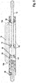
- Fig. 1 shows a longitudinal sectional view of a gas pressure spring according to preferred embodiments of the invention.
- the gas pressure spring 1 has a first hollow chamber 10.
- the first hollow chamber 10 has a first axial end section 10a and a second axial end section 10b.
- the first hollow chamber 10 further has an opening 11 at the second axial end section 10b.
- the gas pressure spring 1 also has an axially displaceable first piston rod 12 which extends through the opening 11.
- the gas pressure spring 1 also has a second hollow chamber 15 arranged in the first hollow chamber 10.
- the gas pressure spring 1 also has a first piston 14, which is connected to the first piston rod 12 at an axial end section 12a of the first piston rod 12 arranged in the second hollow chamber 15 and is movably arranged in the second hollow chamber 15.
- the gas pressure spring 1 also has a second piston 16 arranged movably between the first axial end section 10a and the first piston 14 in the second hollow chamber 15.
- the gas pressure spring 1 also has means 18 for locking and releasing the second piston 16 for adjusting a stroke of the first piston rod 12.
- the means 18 for locking and releasing the second piston 16 have a between the first axial end portion 10a of the first chamber 10 and the in the second hollow chamber 15 arranged second piston 16 arranged valve device 20.
- the second hollow chamber 15 has a first chamber volume V1 and a second chamber volume V2 which is subdivided by the second piston 16 which is sealed off from an inner surface 15a of the second hollow chamber 15 by a first sealant 21.
- the valve device 20 is designed to fluidly connect and separate the first chamber volume V1 and the second chamber volume V2.
- the first chamber volume V1 and the second chamber volume V2 are filled with a pressure medium.
- the pressure medium is preferably formed by nitrogen.
- the first chamber volume V1 is arranged between the valve device 20 and the second piston 16.
- the second chamber volume V2 is arranged between the second piston 16 and a bearing unit 22 arranged on the second axial end section 10b of the first hollow chamber 10.
- the valve device 20 is sealed off from the second hollow chamber 15 by a second sealant 23 and the bearing unit 22 is sealed off from the first hollow chamber 10 by a third sealant 23a.
- the valve device 20 has a valve body 24 and a valve 26 arranged in an opening 25 formed in the axial direction A of the valve body 24.
- the valve 26 is preferably formed by a 2/2-way valve.
- a pneumatically actuable piston 28 is arranged which is movable in the first hollow chamber 10.
- a compressed air switch 30 is arranged which is in pneumatic connection with the pneumatically actuated piston 28.
- the pneumatically actuated piston 28 has a projection 28a.
- the projection 28a can be inserted at least in sections into the opening 25 formed in the valve body 24.
- the projection 28a and the opening 25 formed in the valve body 24 can have any geometric shape.
- the projection 28a and the opening 25 preferably have have the same geometric shape so that they can be interlocked.
- the valve 26 is arranged in the opening 25 of the valve body 24 in such a way that when the pneumatically actuated piston 28 is opened by opening the compressed air switch 30 and thereby pressurized, the pneumatically actuated piston 28 is axially displaced in the direction of the valve body 24 of the projection 28a pneumatically actuated piston 28 is designed to move the valve 26 from a closed position P1 to an open position P2. Furthermore, the pneumatically actuated piston 28 is sealed against an inner surface of the first hollow chamber 10 by a sixth sealing element.
- the valve body 24 has a tap hole 31 formed in the region of the opening 25 and extending essentially in the radial direction R of the gas pressure spring 1.
- the tap hole 31 communicates with a cavity 32 formed between the first hollow chamber 10 and the second hollow chamber 15 in the radial direction R of the gas pressure spring 1.
- the cavity 32 is fluidly connected to the second chamber volume V2.
- the valve 26 is designed to carry out a gas exchange between the first chamber volume V1 to the second chamber volume V2 in the open position P2 and to block a gas exchange between the first chamber volume V1 and the second chamber volume V2 in the closed position P1.
- the valve 26 In the open position P1, the valve 26 has a fluidic connection to the first chamber volume V1, the valve 26 preferably penetrating a membrane 34 arranged in the second hollow chamber 15 between the valve body 24 and the first chamber volume V1. Alternatively, a connection can be made through the valve 26 to the first chamber volume V1 by other means.
- the valve body 24 has a return spring 36, which is arranged in the opening 25 of the valve body 24 and applies a spring force F to the pneumatically actuated piston 28.
- F spring force
- the second piston rod 38 emerges from the first piston rod 12 in the region of the first piston 14.
- a seal 39 is arranged between the first piston 14 and the second piston rod 38.
- the second axial end section 10b of the first hollow chamber 10 is closed by a cover 44 which is sealed off from the first hollow chamber 10 by means of a fourth sealing means 40.
- the compressed air switch 30 is preferably arranged in the cover 44 of the gas pressure spring 1.
- the cover 44 has a corresponding recess for this.
- the compressed air switch 30 is connected to the pneumatically actuated piston 28 by a line 41 formed in the cover 44.
- the valve device 20 is sealed off from the inner surface of the first cavity 10 by a fifth sealing element 27.
- the valve device 20 is also arranged in a fixed position in the first hollow chamber 10 of the gas pressure spring 1. This is realized by caulking the gas pressure spring 1 on an outer surface of the gas pressure spring 1, as a result of which a wall of the first hollow chamber 10 is caulked with the valve device 20 and the valve device 20 is thus arranged in a fixed position within the first hollow chamber 10.
- the second hollow chamber 15 is in the same way by applying or applying an embossing stamp on the outer surface of the gas pressure spring 1 with the first hollow chamber 10 caulked. The same applies to the bearing unit 22, which is caulked to the first hollow chamber 10 at the second axial end section 10b.
- FIG. 1 The illustration shown shows the valve 26 of the valve device 20 in the first, closed position. In this position, gas exchange between the first chamber volume V1 and the second chamber volume V2 is blocked.
- the second piston 16 is thus positioned in a fixed position in the second hollow chamber 15 of the gas pressure spring 1.
- the stroke of the first piston rod 12 is thus limited to an area between the second piston 16 and the bearing unit 22, which in the in Fig. 1 shown representation corresponds to approximately half of the possible stroke of the first piston rod 12.
- Fig. 2 shows a longitudinal sectional view of the gas pressure spring according to the preferred embodiment of the invention.
- the valve 26 is also arranged in the first, closed position P1.
- the second piston 16 is in the same position as in FIG Fig. 1 shown positioned in the second hollow chamber 15.
- the first piston is in the Fig. 2 shown shown spaced from the second piston and is positioned within a possible deflection range of the piston in the second chamber volume V2 of the second hollow chamber 15.
- Fig. 3 shows a longitudinal sectional view of the gas pressure spring according to the preferred embodiment of the invention.
- the valve 26 is shown in the open, second position P2, in which an end section of the valve 26 penetrates the membrane 34 and thus gas exchange between the first chamber volume V1 and the second chamber volume V2 via the tap hole 31 and between the first hollow chamber 10 and the second hollow chamber 15 in the radial direction R of the gas pressure spring 1 formed cavity 32.
- the second piston 16 is thus now freely movable in the second hollow chamber 15 in the axial direction of the gas pressure spring 1. As a result, the stroke of the first piston rod 12 can be adjusted.
- Fig. 4 shows a longitudinal sectional view of the gas pressure spring according to the preferred embodiment of the invention.
- the valve 26 is shown in the open position P2.
- the first piston 14 and the second piston 16 are retracted into the gas pressure spring 1 in their maximum position.
- the first piston rod 12 thus has the maximum available stroke available.
- Fig. 5 shows a longitudinal sectional view of the gas pressure spring according to a further preferred embodiment of the invention.
- the second hollow chamber 15 is arranged outside the first hollow chamber 10.
- the second hollow chamber 15 communicates fluidically with the first hollow chamber 10 at a first axial end section 15b in the region of the valve body 24.
- the second hollow chamber 15 also communicates fluidically with the first chamber volume V1 at a second axial end section 15c.
- the first piston 14 and the second piston 16 are arranged in the first chamber volume V1 and at the same time in the first hollow chamber 10, the first piston rod 12 being essentially hollow, in a cavity 12b of the first piston rod 12 at least at intervals a substantially hollow second piston rod 38 is arranged, the second piston 16 being connected to the second piston rod 38 at an axial end section 38a of the second piston rod 38 facing the first axial end section 10a of the first hollow chamber 10.
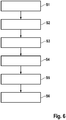
- Fig. 6 shows a flow diagram of a method for operating the gas pressure spring according to the preferred and the further preferred embodiment of the invention.
- the method comprises providing S1 a first hollow chamber which has a first axial end section and a second axial end section, the first hollow chamber having an opening at the second axial end section.
- the method further comprises providing S2 a first piston rod that extends through the opening and is axially displaceable.
- the method also includes providing S3 a second hollow chamber arranged in or outside the first hollow chamber.
- the method further comprises providing S4 a first piston which is connected to the first piston rod at an axial end section of the first piston rod arranged in the first hollow chamber or the second hollow chamber and is movably arranged in the first hollow chamber or the second hollow chamber.
- the method further comprises providing S5 a second piston movably arranged between the first axial end section and the first piston in the first hollow chamber or the second hollow chamber.
- the method further comprises locking and releasing S6 of the second piston for adjusting a stroke of the first piston rod by means.
- a shape, dimension and / or a nature of the components of the gas pressure spring can be changed.
Landscapes
- Engineering & Computer Science (AREA)
- General Engineering & Computer Science (AREA)
- Mechanical Engineering (AREA)
- Fluid-Damping Devices (AREA)
Claims (13)
- Ressort à pression de gaz (1), comportant une première chambre creuse (10) qui comprend une première partie d'extrémité axiale (10a) et une deuxième partie d'extrémité axiale (10b), la première chambre creuse (10) comprenant une ouverture (11) au niveau de la deuxième partie d'extrémité axiale (10b) ;
comportant une première tige de piston (12) déplaçable axialement et s'étendant à travers l'ouverture (11) ;
comportant une deuxième chambre creuse (15) disposée dans la première chambre creuse (10) ou à l'extérieur de celle-ci ;
comportant un premier piston (14), lequel est relié à la première tige de piston (12) au niveau d'une partie d'extrémité axiale (12a), disposée dans la première chambre creuse (10) ou la deuxième chambre creuse (15), de la première tige de piston (12) et lequel est disposé de manière mobile dans la première chambre creuse (10) ou la deuxième chambre creuse (15) ;
comportant un deuxième piston (16) disposé de manière mobile entre la première partie d'extrémité axiale (10a) et le premier piston (14) dans la première chambre creuse (10) ou la deuxième chambre creuse (15) ; et comportant
des moyens (18) de fixation et de libération du deuxième piston (16) pour régler une course de la première tige de piston (12),
caractérisé en ce que
le premier piston (14) et le deuxième piston (16) sont disposés dans le premier volume de chambre (V1), la première tige de piston (12) étant réalisée de manière sensiblement creuse, une deuxième tige de piston (38) réalisée de manière sensiblement creuse étant disposée, au moins dans certaines régions, dans une cavité (12b) de la première tige de piston (12), le deuxième piston (16) étant relié à une partie d'extrémité axiale de la deuxième tige de piston (38), laquelle partie d'extrémité axiale est tournée vers la première partie d'extrémité axiale (10a) de la première chambre creuse (10). - Ressort à pression de gaz selon la revendication 1, caractérisé en ce que lés moyens (18) de fixation et de libération du deuxième piston (16) comprennent un dispositif de soupape (20) disposé entre la première partie d'extrémité axiale (10a) de la première chambre (10) et le deuxième piston (16) disposé dans la deuxième chambre creuse (15).
- Ressort à pression de gaz selon la revendication 2, caractérisé en ce que la deuxième chambre creuse (15) comprend un premier volume de chambre (V1) divisé par le deuxième piston (16) fermé hermétiquement par un premier moyen d'étanchéité (21) vis-à-vis d'une surface intérieure (15a) de la deuxième chambre creuse (15) et un deuxième volume de chambre (V2), le dispositif de soupape (20) étant conçu pour relier fluidiquement le premier volume de chambre (V1) et le deuxième volume de chambre (V2) et pour les séparer.
- Ressort à pression de gaz selon la revendication 3, caractérisé en ce que le premier volume de chambre (V1) et le deuxième volume de chambre (V2) sont remplis d'un fluide sous pression, de préférence d'azote, le premier volume de chambre (V1) étant disposé entre le dispositif de soupape (20) et le deuxième piston (16) et le deuxième volume de chambre (V2) étant disposé entre le deuxième piston (16) et une unité de palier (22) disposée au niveau de la deuxième partie d'extrémité axiale (10b) de la première chambre creuse (10), le dispositif de soupape (20) étant fermé hermétiquement par un deuxième moyen d'étanchéité (23) vis-à-vis de la deuxième chambre creuse (15) et l'unité de palier (22) étant fermée hermétiquement par un troisième moyen d'étanchéité (23a) vis-à-vis de la première chambre creuse (10).
- Ressort à pression de gaz selon la revendication 3 ou 4, caractérisé en ce que le dispositif de soupape (20) comprend un corps de soupape (24) et une soupape (26), de préférence une soupape à 2/2 voies, disposée dans une ouverture (25) formée dans la direction axiale (A) du corps de soupape (24), un piston (28) mobile dans la première chambre creuse (10) et pouvant être actionné de manière pneumatique étant disposé entre le corps de soupape (24) et la première partie d'extrémité axiale (10a) de la première chambre creuse (10), et un commutateur à air comprimé (30) en liaison pneumatique avec le piston (28) pouvant être actionné de manière pneumatique étant disposé dans la région de la première partie d'extrémité axiale (10a) de la première chambre creuse (10).
- Ressort à pression de gaz selon la revendication 5, caractérisé en ce que le piston (28) pouvant être actionné de manière pneumatique comprend une saillie (28a), laquelle peut être insérée, au moins dans certaines régions, dans l'ouverture (25) formée dans le corps de soupape (24), et la soupape (26) étant disposée dans l'ouverture (25) du corps de soupape (24) de telle sorte qu'en cas de déplacement axial du piston (28) pouvant être actionné de manière pneumatique en direction du corps de soupape (24), lequel déplacement axial est provoqué par l'ouverture du commutateur à air comprimé (30) et l'application de pression, ainsi provoquée, sur le piston (28) pouvant être actionné de manière pneumatique, la saillie (28a) du piston (28) pouvant être actionné de manière pneumatique est conçue pour déplacer la soupape (26) d'une position fermée (P1) à une position ouverte (P2).
- Ressort à pression de gaz selon la revendication 6, caractérisé en ce que le corps de soupape (24) comprend un alésage percé (31) formé dans la région de l'ouverture (25) et s'étendant sensiblement dans la direction radiale (R) du ressort à pression de gaz (1), lequel alésage communique avec une cavité (32) formée entre la première chambre creuse (10) et la deuxième chambre creuse (15) dans la direction radiale (R) du ressort à pression de gaz (1), la cavité (32) étant reliée fluidiquement au deuxième volume de chambre (V2), la soupape (26) étant conçue pour effectuer un échange de gaz entre le premier volume de chambre (V1) et le deuxième volume de chambre (V2) dans la position ouverte (P2) et pour bloquer un échange de gaz entre le premier volume de chambre (V1) et le deuxième volume de chambre (V2) dans la position fermée (P1).
- Ressort à pression de gaz selon l'une des revendications 5 à 7, caractérisé en ce que la soupape (26) présente, dans la position ouverte (P2), une liaison fluidique avec le premier volume de chambre (V1), la soupape (26) traversant de préférence une membrane (34) disposée dans la deuxième chambre creuse (15) entre le corps de soupape (24) et le premier volume de chambre (V1).
- Ressort à pression de gaz selon l'une des revendications 5 à 8, caractérisé en ce que le corps de soupape (24) comprend un ressort de rappel (36), lequel est disposé dans l'ouverture (25) du corps de soupape (24) et soumet le piston (28) pouvant être actionné de manière pneumatique à une force de ressort (F).
- Ressort à pression de gaz selon la revendication 5 ou 6, caractérisé en ce que la deuxième chambre creuse (15) est disposée à l'extérieur de la première chambre creuse (10), la deuxième chambre creuse (15) étant en communication fluidique avec la première chambre creuse (10) au niveau d'une première partie d'extrémité axiale (15b) dans la région du corps de soupape (24), et la deuxième chambre creuse (15) étant en communication fluidique avec le premier volume de chambre (V1) au niveau d'une deuxième partie d'extrémité axiale (15c).
- Ressort à pression de gaz selon l'une des revendications précédentes, caractérisé en ce qu'une position minimale de la première tige de piston (12) peut être réglée grâce aux moyens (18) de fixation et de libération du deuxième piston (16) dans la deuxième chambre creuse (15).
- Ressort à pression de gaz selon l'une des revendications précédentes, caractérisé en ce que la deuxième tige de piston (38) sort de la première tige de piston (12) dans la région du premier piston (14), un joint d'étanchéité (39) étant disposé entre le premier piston (14) et la deuxième tige de piston (38).
- Ressort à pression de gaz selon l'une des revendications précédentes, caractérisé en ce que la deuxième partie d'extrémité axiale (10b) de la première chambre creuse (10) est fermée au moyen d'un couvercle (44) fermé hermétiquement au moyen d'un quatrième moyen d'étanchéité (40) vis-à-vis de la première chambre creuse (10).
Applications Claiming Priority (1)
| Application Number | Priority Date | Filing Date | Title |
|---|---|---|---|
| DE102016225479.0A DE102016225479A1 (de) | 2016-12-19 | 2016-12-19 | Gasdruckfeder und Verfahren zum Betreiben einer Gasdruckfeder |
Publications (2)
| Publication Number | Publication Date |
|---|---|
| EP3336376A1 EP3336376A1 (fr) | 2018-06-20 |
| EP3336376B1 true EP3336376B1 (fr) | 2020-02-12 |
Family
ID=60781518
Family Applications (1)
| Application Number | Title | Priority Date | Filing Date |
|---|---|---|---|
| EP17207201.9A Active EP3336376B1 (fr) | 2016-12-19 | 2017-12-14 | Ressort à gaz |
Country Status (2)
| Country | Link |
|---|---|
| EP (1) | EP3336376B1 (fr) |
| DE (1) | DE102016225479A1 (fr) |
Families Citing this family (1)
| Publication number | Priority date | Publication date | Assignee | Title |
|---|---|---|---|---|
| CN114458804A (zh) * | 2022-01-17 | 2022-05-10 | 宁波威森搏乐机械制造有限公司 | 高精密气液微动自控阀 |
Family Cites Families (8)
| Publication number | Priority date | Publication date | Assignee | Title |
|---|---|---|---|---|
| JPS5144768A (en) * | 1974-10-14 | 1976-04-16 | Tokico Ltd | Gasusupuringuniokerurotsukusochi |
| NL9001634A (nl) * | 1990-07-18 | 1992-02-17 | Imasaco Ag | Instelbare kolom. |
| DE4127917C2 (de) * | 1991-08-23 | 2000-01-20 | Stabilus Gmbh | Federungseinrichtung |
| DE19547326C2 (de) * | 1995-12-19 | 2002-03-14 | Guenther Hahn | Blockierbare Gasfeder mit metallischen Dichtflächen |
| US6698729B2 (en) * | 2001-06-15 | 2004-03-02 | Mark A. Popjoy | Gas spring having a controllable output force |
| DE10238448C5 (de) * | 2002-08-22 | 2008-01-03 | Daimlerchrysler Ag | Variable Gasdruckfeder |
| DE10329468B3 (de) * | 2003-07-01 | 2004-11-18 | Stabilus Gmbh | Gasfeder |
| DE102011116345B4 (de) | 2011-10-05 | 2014-05-08 | Benjamin Aktan | Verfahren zum Modifizieren einer Gasdruckfeder für eine Kraftfahrzeug-Heckklappe |
-
2016
- 2016-12-19 DE DE102016225479.0A patent/DE102016225479A1/de not_active Withdrawn
-
2017
- 2017-12-14 EP EP17207201.9A patent/EP3336376B1/fr active Active
Non-Patent Citations (1)
| Title |
|---|
| None * |
Also Published As
| Publication number | Publication date |
|---|---|
| EP3336376A1 (fr) | 2018-06-20 |
| DE102016225479A1 (de) | 2018-06-21 |
Similar Documents
| Publication | Publication Date | Title |
|---|---|---|
| EP2234135B1 (fr) | Agencement de vannes | |
| DE102014109097A1 (de) | Hydraulikventil | |
| EP1646812A1 (fr) | Arbre a guide d'huile | |
| WO2012123181A1 (fr) | Ensemble vérin de commutation | |
| EP2628959B1 (fr) | Servosoupape | |
| DE102010011239A1 (de) | Fluidische Betätigungsaktuatorik mit einem zweistückigen Zylindergehäuse und Verfahren zur Herstellung einer solchen Betätigungsaktuatorik | |
| EP1752691A1 (fr) | Vanne de commande et son procédé de fabrication | |
| DE102010026977B4 (de) | Verfahren zur Schildsteuerung | |
| WO2008071567A1 (fr) | Système de commande pour une boîte de vitesses | |
| DE102021207650A1 (de) | Schieberventil mit geringer Neigung zum hydraulischen Klemmen | |
| DE102009016983A1 (de) | Pneumatisch gesteuertes 3/2-Wegeventil zur Steuerung einer pneumatischen Feststellbremse und Verfahren zum Betreiben eines pneumatisch gesteuerten 3/2-Wegeventils | |
| DE102016110855A1 (de) | Druckhalteventil für ein reversibles Verbinden mit einer Luftleitung | |
| EP3336376B1 (fr) | Ressort à gaz | |
| EP2226513A2 (fr) | Unité de blocage, notamment pour une unité de fermeture de moule | |
| DE102017218140A1 (de) | Drucksystemkomponente, Werkzeug zur Demontage einer Drucksystemkomponente, Drucksystem mit einer Drucksystemkomponente und Verfahren zur Demontage einer Drucksystemkomponente | |
| WO2018134244A1 (fr) | Ensemble cylindre-piston dont le cylindre est composé d'un matériau composite renforcé de fibres | |
| DE19812086C2 (de) | Hydraulikfluid-Durchgangs-Verteilventil | |
| EP2742246B1 (fr) | Soupape à tiroir munie d'un tiroir pouvant être soumis à l'action d'un actionneur | |
| DE2819439A1 (de) | Steuerventilvorrichtung fuer eine hydraulische bremsanlage | |
| DE102015104334A1 (de) | Vorrichtung zur Herstellung eines doppelwandigen Rohres | |
| DE69601157T2 (de) | Druckreduzierventil | |
| DE102018202827B4 (de) | Feder-Dämpfersystem mit verzögerungsfrei umschaltbarer Federrate | |
| DE102006022551B3 (de) | Hauptbremszylinder | |
| EP4515129A1 (fr) | Électrovanne à amortissement amélioré et son procédé de fabrication | |
| EP3073127B1 (fr) | Composant piston-cylindre pour verin a pression, verin a pression et boite de transfert |
Legal Events
| Date | Code | Title | Description |
|---|---|---|---|
| PUAI | Public reference made under article 153(3) epc to a published international application that has entered the european phase |
Free format text: ORIGINAL CODE: 0009012 |
|
| STAA | Information on the status of an ep patent application or granted ep patent |
Free format text: STATUS: THE APPLICATION HAS BEEN PUBLISHED |
|
| AK | Designated contracting states |
Kind code of ref document: A1 Designated state(s): AL AT BE BG CH CY CZ DE DK EE ES FI FR GB GR HR HU IE IS IT LI LT LU LV MC MK MT NL NO PL PT RO RS SE SI SK SM TR |
|
| AX | Request for extension of the european patent |
Extension state: BA ME |
|
| STAA | Information on the status of an ep patent application or granted ep patent |
Free format text: STATUS: REQUEST FOR EXAMINATION WAS MADE |
|
| 17P | Request for examination filed |
Effective date: 20181220 |
|
| RBV | Designated contracting states (corrected) |
Designated state(s): AL AT BE BG CH CY CZ DE DK EE ES FI FR GB GR HR HU IE IS IT LI LT LU LV MC MK MT NL NO PL PT RO RS SE SI SK SM TR |
|
| GRAP | Despatch of communication of intention to grant a patent |
Free format text: ORIGINAL CODE: EPIDOSNIGR1 |
|
| STAA | Information on the status of an ep patent application or granted ep patent |
Free format text: STATUS: GRANT OF PATENT IS INTENDED |
|
| INTG | Intention to grant announced |
Effective date: 20190710 |
|
| GRAS | Grant fee paid |
Free format text: ORIGINAL CODE: EPIDOSNIGR3 |
|
| GRAA | (expected) grant |
Free format text: ORIGINAL CODE: 0009210 |
|
| STAA | Information on the status of an ep patent application or granted ep patent |
Free format text: STATUS: THE PATENT HAS BEEN GRANTED |
|
| AK | Designated contracting states |
Kind code of ref document: B1 Designated state(s): AL AT BE BG CH CY CZ DE DK EE ES FI FR GB GR HR HU IE IS IT LI LT LU LV MC MK MT NL NO PL PT RO RS SE SI SK SM TR |
|
| REG | Reference to a national code |
Ref country code: GB Ref legal event code: FG4D Free format text: NOT ENGLISH |
|
| REG | Reference to a national code |
Ref country code: CH Ref legal event code: EP |
|
| REG | Reference to a national code |
Ref country code: AT Ref legal event code: REF Ref document number: 1232512 Country of ref document: AT Kind code of ref document: T Effective date: 20200215 |
|
| REG | Reference to a national code |
Ref country code: IE Ref legal event code: FG4D Free format text: LANGUAGE OF EP DOCUMENT: GERMAN |
|
| REG | Reference to a national code |
Ref country code: DE Ref legal event code: R096 Ref document number: 502017003767 Country of ref document: DE |
|
| RAP2 | Party data changed (patent owner data changed or rights of a patent transferred) |
Owner name: ROBERT BOSCH GMBH |
|
| PG25 | Lapsed in a contracting state [announced via postgrant information from national office to epo] |
Ref country code: NO Free format text: LAPSE BECAUSE OF FAILURE TO SUBMIT A TRANSLATION OF THE DESCRIPTION OR TO PAY THE FEE WITHIN THE PRESCRIBED TIME-LIMIT Effective date: 20200512 Ref country code: FI Free format text: LAPSE BECAUSE OF FAILURE TO SUBMIT A TRANSLATION OF THE DESCRIPTION OR TO PAY THE FEE WITHIN THE PRESCRIBED TIME-LIMIT Effective date: 20200212 Ref country code: RS Free format text: LAPSE BECAUSE OF FAILURE TO SUBMIT A TRANSLATION OF THE DESCRIPTION OR TO PAY THE FEE WITHIN THE PRESCRIBED TIME-LIMIT Effective date: 20200212 |
|
| REG | Reference to a national code |
Ref country code: LT Ref legal event code: MG4D |
|
| REG | Reference to a national code |
Ref country code: NL Ref legal event code: MP Effective date: 20200212 |
|
| PG25 | Lapsed in a contracting state [announced via postgrant information from national office to epo] |
Ref country code: HR Free format text: LAPSE BECAUSE OF FAILURE TO SUBMIT A TRANSLATION OF THE DESCRIPTION OR TO PAY THE FEE WITHIN THE PRESCRIBED TIME-LIMIT Effective date: 20200212 Ref country code: GR Free format text: LAPSE BECAUSE OF FAILURE TO SUBMIT A TRANSLATION OF THE DESCRIPTION OR TO PAY THE FEE WITHIN THE PRESCRIBED TIME-LIMIT Effective date: 20200513 Ref country code: BG Free format text: LAPSE BECAUSE OF FAILURE TO SUBMIT A TRANSLATION OF THE DESCRIPTION OR TO PAY THE FEE WITHIN THE PRESCRIBED TIME-LIMIT Effective date: 20200512 Ref country code: IS Free format text: LAPSE BECAUSE OF FAILURE TO SUBMIT A TRANSLATION OF THE DESCRIPTION OR TO PAY THE FEE WITHIN THE PRESCRIBED TIME-LIMIT Effective date: 20200612 Ref country code: LV Free format text: LAPSE BECAUSE OF FAILURE TO SUBMIT A TRANSLATION OF THE DESCRIPTION OR TO PAY THE FEE WITHIN THE PRESCRIBED TIME-LIMIT Effective date: 20200212 Ref country code: SE Free format text: LAPSE BECAUSE OF FAILURE TO SUBMIT A TRANSLATION OF THE DESCRIPTION OR TO PAY THE FEE WITHIN THE PRESCRIBED TIME-LIMIT Effective date: 20200212 |
|
| PG25 | Lapsed in a contracting state [announced via postgrant information from national office to epo] |
Ref country code: NL Free format text: LAPSE BECAUSE OF FAILURE TO SUBMIT A TRANSLATION OF THE DESCRIPTION OR TO PAY THE FEE WITHIN THE PRESCRIBED TIME-LIMIT Effective date: 20200212 |
|
| PG25 | Lapsed in a contracting state [announced via postgrant information from national office to epo] |
Ref country code: LT Free format text: LAPSE BECAUSE OF FAILURE TO SUBMIT A TRANSLATION OF THE DESCRIPTION OR TO PAY THE FEE WITHIN THE PRESCRIBED TIME-LIMIT Effective date: 20200212 Ref country code: ES Free format text: LAPSE BECAUSE OF FAILURE TO SUBMIT A TRANSLATION OF THE DESCRIPTION OR TO PAY THE FEE WITHIN THE PRESCRIBED TIME-LIMIT Effective date: 20200212 Ref country code: CZ Free format text: LAPSE BECAUSE OF FAILURE TO SUBMIT A TRANSLATION OF THE DESCRIPTION OR TO PAY THE FEE WITHIN THE PRESCRIBED TIME-LIMIT Effective date: 20200212 Ref country code: PT Free format text: LAPSE BECAUSE OF FAILURE TO SUBMIT A TRANSLATION OF THE DESCRIPTION OR TO PAY THE FEE WITHIN THE PRESCRIBED TIME-LIMIT Effective date: 20200705 Ref country code: DK Free format text: LAPSE BECAUSE OF FAILURE TO SUBMIT A TRANSLATION OF THE DESCRIPTION OR TO PAY THE FEE WITHIN THE PRESCRIBED TIME-LIMIT Effective date: 20200212 Ref country code: EE Free format text: LAPSE BECAUSE OF FAILURE TO SUBMIT A TRANSLATION OF THE DESCRIPTION OR TO PAY THE FEE WITHIN THE PRESCRIBED TIME-LIMIT Effective date: 20200212 Ref country code: SM Free format text: LAPSE BECAUSE OF FAILURE TO SUBMIT A TRANSLATION OF THE DESCRIPTION OR TO PAY THE FEE WITHIN THE PRESCRIBED TIME-LIMIT Effective date: 20200212 Ref country code: RO Free format text: LAPSE BECAUSE OF FAILURE TO SUBMIT A TRANSLATION OF THE DESCRIPTION OR TO PAY THE FEE WITHIN THE PRESCRIBED TIME-LIMIT Effective date: 20200212 Ref country code: SK Free format text: LAPSE BECAUSE OF FAILURE TO SUBMIT A TRANSLATION OF THE DESCRIPTION OR TO PAY THE FEE WITHIN THE PRESCRIBED TIME-LIMIT Effective date: 20200212 |
|
| REG | Reference to a national code |
Ref country code: DE Ref legal event code: R097 Ref document number: 502017003767 Country of ref document: DE |
|
| PLBE | No opposition filed within time limit |
Free format text: ORIGINAL CODE: 0009261 |
|
| STAA | Information on the status of an ep patent application or granted ep patent |
Free format text: STATUS: NO OPPOSITION FILED WITHIN TIME LIMIT |
|
| 26N | No opposition filed |
Effective date: 20201113 |
|
| PG25 | Lapsed in a contracting state [announced via postgrant information from national office to epo] |
Ref country code: IT Free format text: LAPSE BECAUSE OF FAILURE TO SUBMIT A TRANSLATION OF THE DESCRIPTION OR TO PAY THE FEE WITHIN THE PRESCRIBED TIME-LIMIT Effective date: 20200212 |
|
| PG25 | Lapsed in a contracting state [announced via postgrant information from national office to epo] |
Ref country code: PL Free format text: LAPSE BECAUSE OF FAILURE TO SUBMIT A TRANSLATION OF THE DESCRIPTION OR TO PAY THE FEE WITHIN THE PRESCRIBED TIME-LIMIT Effective date: 20200212 Ref country code: SI Free format text: LAPSE BECAUSE OF FAILURE TO SUBMIT A TRANSLATION OF THE DESCRIPTION OR TO PAY THE FEE WITHIN THE PRESCRIBED TIME-LIMIT Effective date: 20200212 |
|
| REG | Reference to a national code |
Ref country code: DE Ref legal event code: R119 Ref document number: 502017003767 Country of ref document: DE |
|
| REG | Reference to a national code |
Ref country code: CH Ref legal event code: PL |
|
| PG25 | Lapsed in a contracting state [announced via postgrant information from national office to epo] |
Ref country code: MC Free format text: LAPSE BECAUSE OF FAILURE TO SUBMIT A TRANSLATION OF THE DESCRIPTION OR TO PAY THE FEE WITHIN THE PRESCRIBED TIME-LIMIT Effective date: 20200212 |
|
| REG | Reference to a national code |
Ref country code: BE Ref legal event code: MM Effective date: 20201231 |
|
| PG25 | Lapsed in a contracting state [announced via postgrant information from national office to epo] |
Ref country code: IE Free format text: LAPSE BECAUSE OF NON-PAYMENT OF DUE FEES Effective date: 20201214 Ref country code: FR Free format text: LAPSE BECAUSE OF NON-PAYMENT OF DUE FEES Effective date: 20201231 Ref country code: LU Free format text: LAPSE BECAUSE OF NON-PAYMENT OF DUE FEES Effective date: 20201214 |
|
| PG25 | Lapsed in a contracting state [announced via postgrant information from national office to epo] |
Ref country code: LI Free format text: LAPSE BECAUSE OF NON-PAYMENT OF DUE FEES Effective date: 20201231 Ref country code: DE Free format text: LAPSE BECAUSE OF NON-PAYMENT OF DUE FEES Effective date: 20210701 Ref country code: CH Free format text: LAPSE BECAUSE OF NON-PAYMENT OF DUE FEES Effective date: 20201231 |
|
| PG25 | Lapsed in a contracting state [announced via postgrant information from national office to epo] |
Ref country code: TR Free format text: LAPSE BECAUSE OF FAILURE TO SUBMIT A TRANSLATION OF THE DESCRIPTION OR TO PAY THE FEE WITHIN THE PRESCRIBED TIME-LIMIT Effective date: 20200212 Ref country code: MT Free format text: LAPSE BECAUSE OF FAILURE TO SUBMIT A TRANSLATION OF THE DESCRIPTION OR TO PAY THE FEE WITHIN THE PRESCRIBED TIME-LIMIT Effective date: 20200212 Ref country code: CY Free format text: LAPSE BECAUSE OF FAILURE TO SUBMIT A TRANSLATION OF THE DESCRIPTION OR TO PAY THE FEE WITHIN THE PRESCRIBED TIME-LIMIT Effective date: 20200212 |
|
| PG25 | Lapsed in a contracting state [announced via postgrant information from national office to epo] |
Ref country code: MK Free format text: LAPSE BECAUSE OF FAILURE TO SUBMIT A TRANSLATION OF THE DESCRIPTION OR TO PAY THE FEE WITHIN THE PRESCRIBED TIME-LIMIT Effective date: 20200212 Ref country code: AL Free format text: LAPSE BECAUSE OF FAILURE TO SUBMIT A TRANSLATION OF THE DESCRIPTION OR TO PAY THE FEE WITHIN THE PRESCRIBED TIME-LIMIT Effective date: 20200212 |
|
| PG25 | Lapsed in a contracting state [announced via postgrant information from national office to epo] |
Ref country code: BE Free format text: LAPSE BECAUSE OF NON-PAYMENT OF DUE FEES Effective date: 20201231 |
|
| GBPC | Gb: european patent ceased through non-payment of renewal fee |
Effective date: 20211214 |
|
| PG25 | Lapsed in a contracting state [announced via postgrant information from national office to epo] |
Ref country code: GB Free format text: LAPSE BECAUSE OF NON-PAYMENT OF DUE FEES Effective date: 20211214 |
|
| REG | Reference to a national code |
Ref country code: AT Ref legal event code: MM01 Ref document number: 1232512 Country of ref document: AT Kind code of ref document: T Effective date: 20221214 |
|
| PG25 | Lapsed in a contracting state [announced via postgrant information from national office to epo] |
Ref country code: AT Free format text: LAPSE BECAUSE OF NON-PAYMENT OF DUE FEES Effective date: 20221214 |
|
| PG25 | Lapsed in a contracting state [announced via postgrant information from national office to epo] |
Ref country code: AT Free format text: LAPSE BECAUSE OF NON-PAYMENT OF DUE FEES Effective date: 20221214 |
|
| PGFP | Annual fee paid to national office [announced via postgrant information from national office to epo] |
Ref country code: AT Payment date: 20260410 Year of fee payment: 5 |