EP3336408A1 - Structure pliable, procédé de fabrication de structure pliable, dispositif de fabrication de structure pliable, et programme - Google Patents
Structure pliable, procédé de fabrication de structure pliable, dispositif de fabrication de structure pliable, et programme Download PDFInfo
- Publication number
- EP3336408A1 EP3336408A1 EP16837093.0A EP16837093A EP3336408A1 EP 3336408 A1 EP3336408 A1 EP 3336408A1 EP 16837093 A EP16837093 A EP 16837093A EP 3336408 A1 EP3336408 A1 EP 3336408A1
- Authority
- EP
- European Patent Office
- Prior art keywords
- foldable structure
- array
- surface array
- wall surface
- tubular
- Prior art date
- Legal status (The legal status is an assumption and is not a legal conclusion. Google has not performed a legal analysis and makes no representation as to the accuracy of the status listed.)
- Granted
Links
Images








Classifications
-
- E—FIXED CONSTRUCTIONS
- E04—BUILDING
- E04B—GENERAL BUILDING CONSTRUCTIONS; WALLS, e.g. PARTITIONS; ROOFS; FLOORS; CEILINGS; INSULATION OR OTHER PROTECTION OF BUILDINGS
- E04B1/00—Constructions in general; Structures which are not restricted either to walls, e.g. partitions, or floors or ceilings or roofs
- E04B1/343—Structures characterised by movable, separable, or collapsible parts, e.g. for transport
- E04B1/344—Structures characterised by movable, separable, or collapsible parts, e.g. for transport with hinged parts
- E04B1/345—Structures deriving their rigidity from concertina folds
-
- B—PERFORMING OPERATIONS; TRANSPORTING
- B31—MAKING ARTICLES OF PAPER, CARDBOARD OR MATERIAL WORKED IN A MANNER ANALOGOUS TO PAPER; WORKING PAPER, CARDBOARD OR MATERIAL WORKED IN A MANNER ANALOGOUS TO PAPER
- B31B—MAKING CONTAINERS OF PAPER, CARDBOARD OR MATERIAL WORKED IN A MANNER ANALOGOUS TO PAPER
- B31B50/00—Making rigid or semi-rigid containers, e.g. boxes or cartons
- B31B50/006—Controlling; Regulating; Measuring; Improving safety
-
- B—PERFORMING OPERATIONS; TRANSPORTING
- B31—MAKING ARTICLES OF PAPER, CARDBOARD OR MATERIAL WORKED IN A MANNER ANALOGOUS TO PAPER; WORKING PAPER, CARDBOARD OR MATERIAL WORKED IN A MANNER ANALOGOUS TO PAPER
- B31D—MAKING ARTICLES OF PAPER, CARDBOARD OR MATERIAL WORKED IN A MANNER ANALOGOUS TO PAPER, NOT PROVIDED FOR IN SUBCLASSES B31B OR B31C
- B31D5/00—Multiple-step processes for making three-dimensional [3D] articles
- B31D5/0086—Making hollow objects
-
- B—PERFORMING OPERATIONS; TRANSPORTING
- B31—MAKING ARTICLES OF PAPER, CARDBOARD OR MATERIAL WORKED IN A MANNER ANALOGOUS TO PAPER; WORKING PAPER, CARDBOARD OR MATERIAL WORKED IN A MANNER ANALOGOUS TO PAPER
- B31D—MAKING ARTICLES OF PAPER, CARDBOARD OR MATERIAL WORKED IN A MANNER ANALOGOUS TO PAPER, NOT PROVIDED FOR IN SUBCLASSES B31B OR B31C
- B31D5/00—Multiple-step processes for making three-dimensional [3D] articles
- B31D5/04—Multiple-step processes for making three-dimensional [3D] articles including folding or pleating, e.g. Chinese lanterns
-
- E—FIXED CONSTRUCTIONS
- E01—CONSTRUCTION OF ROADS, RAILWAYS, OR BRIDGES
- E01D—CONSTRUCTION OF BRIDGES, ELEVATED ROADWAYS OR VIADUCTS; ASSEMBLY OF BRIDGES
- E01D4/00—Arch-type bridges
Definitions
- the present invention relates to a foldable structure, a method of manufacturing a foldable structure, a manufacturing device of a foldable structure, and a program.
- a foldable structure deformable between a folded state and a deployed state is conventionally known.
- Patent Document 1 discloses a tubular folding box structure easy to fold with a deployable structure referred to as a Miura-ori as a basic element.
- Non-Patent Document 1 discloses an arch-shaped structure rigid-foldable with one degree of freedom and having flat-foldability.
- Non-Patent Document 2 discloses a structure rigid-foldable with one degree of freedom having bidirectional flat-foldability formed of a flat quadrilateral mesh.
- the conventional foldable structure becomes a mechanism with one degree of freedom and is rigid-foldable when each surface is a rigid body that is not bent, but there is a problem that in a case where a flexible material such as paper, a plastic plate, and a thin metal plate is used for each surface, each surface bends to occur non-uniform extension and contraction, so that the rigid-folding deformation mode cannot be maintained.
- the present invention is achieved in view of the above-described problems, and an object thereof is to provide a foldable structure to which stiffness is imparted so as to inhibit non-uniform extension and contraction even with a flexible material, a method of manufacturing a foldable structure, a manufacturing device of a foldable structure, and a program.
- a foldable structure according to the present invention is a foldable structure provided with at least two tubular structures, in which the two tubular structures include a shared surface array which is continuous shared surfaces shared by the two tubular structures, and a twisting characteristic in the shared surface array of one tubular structure is in a direction opposite to the direction of the twisting characteristic in the shared surface array of the other tubular structure.
- the foldable structure according to the present invention is the above-described foldable structure in which the tubular structures are such that, in a case of transition between a deployed state and a folded state, a propagation amount of a fold angle around the shared surface through one tubular structure is equal to the propagation amount through the other tubular structure.
- the foldable structure according to the present invention is the above-described foldable structure in which the shared surface array is a cylindrical surface in which the shared surfaces are connected by parallel ridge lines, and a wall surface array of one tubular structure is such that the extension of the wall surface to the other side so as to penetrate the cylindrical surface is mirror symmetric with the wall surface array of the other tubular structure with respect to a plane orthogonal to the cylindrical surface.
- the foldable structure according to the present invention is the above-described foldable structure in which the shared surface array is an arbitrary single curved surface, and an internal angle at a tetravalent vertex formed of the shared surface array and the wall surface array of the adjacent tubular structure is such that the sum of opposite angles is 180° or the opposite angles are equal to each other, and a propagation amount of the fold angle through one wall surface array is equal to the propagation amount of the fold angle through the other wall surface array.
- the foldable structure according to the present invention is the above-described foldable structure in which the two tubular structures are Miura-ori tubular structures, and one tubular structure and the other tubular structure are zipper-coupled such that fold line portions intermesh with each other in the shared surface array.
- the foldable structure according to the present invention is the above-described foldable structure in which in a case of transition from a folded state to a deployed state, the tubular structures which are not adjacent to each other so far are adjacent and may be coupled, so that retransition to the folded state may be inhibited.
- the foldable structure according to the present invention is the above-described foldable structure in which a surface of the shared surface array is a conceptual surface formed of a plurality of fold lines.
- the foldable structure according to the present invention is the above-described foldable structure in which the foldable structure is a folding structure or a flat-foldable structure.
- a method of manufacturing a foldable structure according to the present invention is provided with a foldable structure generating step of generating an equivalent foldable structure including two wall surface arrays from a generating surface array, and a tubular structure forming step of forming tubular structures on both sides of the generating surface on the basis of the generating surface array and the two wall surface arrays.
- the method of manufacturing a foldable structure according to the present invention is the above-described method of manufacturing a foldable structure in which the foldable structure generating step generates the generating surface array as a cylindrical surface connected by parallel ridge lines, generates a wall surface array mirror symmetric with an arbitrary wall surface array with respect to a plane orthogonal to the cylindrical surface, and generates the equivalent foldable structure by extending one wall surface array so as to penetrate the generating surface array, and the tubular structure forming step forms the tubular structures from surface arrays offset in parallel on both sides of the generating surface array and surface arrays offset in parallel from the wall surface arrays.
- the method of manufacturing a foldable structure according to the present invention is the above-described method of manufacturing a foldable structure in which the foldable structure generating step generates the equivalent foldable structure by determining an internal angle at each inner vertex such that the sum of opposite angles is 180° and a propagation amount of a fold angle through one wall surface array is equal to the propagation amount of the fold angle through the other wall surface array in a deployment diagram of the foldable structure including the generating surface array and the two wall surface arrays, and the tubular structure forming step forms the tubular structures of surface arrays offset in parallel on both sides of the generating surface array and surface arrays offset in parallel from the wall surface arrays.
- a manufacturing device of a foldable structure is provided with a foldable structure generator which generates an equivalent foldable structure including two wall surface arrays from a generating surface array, and a tubular structure former which forms tubular structures on both sides of the generating surface on the basis of the generating surface array and the two wall surface arrays.
- a program according to the present invention is a program for allowing a computer to execute a method of generating a foldable structure which allows the computer to execute a foldable structure generating step of generating an equivalent foldable structure including two wall surface arrays from a generating surface array, and a tubular structure forming step of forming tubular structures on both sides of the generating surface on the basis of the generating surface array and the two wall surface arrays.
- the present invention there is an effect that it is possible to provide a foldable structure to which stiffness is imparted so as to inhibit non-uniform extension and contraction even if each surface is formed of a flexible material, a method for manufacturing a foldable structure, a manufacturing device of a foldable structure, and a program.
- the foldable structure is a structure which may be folded to be deformed such as a folding structure, a flat-foldable structure, or a rigid-foldable structure.
- Fig. 1 is a perspective view of (A) one Miura-ori tubular structure, (B) two aligned-coupled Miura-ori tubular structures, and (C) two zipper-coupled Miura-ori tubular structures.
- Fig. 2 is an orthographic view illustrating a top view (upper stage) and a front view (lower stage) of Fig. 1 .
- a single Miura-ori tubular structure and (B) the aligned-coupled structure thereof have flat-foldable property, so that they are flat-foldable, and are rigid-foldable with one degree of freedom.
- a "rigid-foldable structure” which is a structure rigid-foldable is a mechanism which may be continuously deformed out of structures formed of a plurality of surfaces continuous with fold lines with each surface being a rigid body not deflected.
- Fig. 3 is a view illustrating the rigid-folding deformation mode ( Figs. 3(a) and (b) in upper stage) in which the non-uniform deformation does not occur at the time of deployment and a twist mode in which the non-uniform deformation occurs at the time of deployment ( Fig. 3(c) and (d) in lower stage).
- one embodiment of the present invention is, as illustrated in Figs. 1(C) and 2(C) , the foldable structure in which one tubular structure and the other tubular structure are not aligned-coupled, but zipper-coupled such that the fold line portions alternately intermeshed.
- Such zipper-coupled foldable structure may prevent the non-uniform extension and contraction by a combination of geometrical structures and maintain the rigid-folding deformation mode.
- Fig. 4 is a view illustrating the twisting direction in a shared surface array of the (B) aligned-coupling
- Fig. 5 is a view illustrating the twisting direction in the shared surface array of the (C) zipper-coupling.
- the inventors of the present application further studied seriously and found the principle of manufacturing a generalized shape maintaining the property of reversal of the twisting direction in the shared surface array with the zipper-coupled tubular structures as a basic structure. That is, they found that various shapes may be manufactured by widely generalizing the principle of positive/negative reversal of the twisting directions in addition to the combination of the Miura-ori tubular structures.
- the principle that the shear deformation of a parallelogram at a certain cross-sectional position corresponds to the extension and contraction ratio at that position and the gradient of the extension and contraction ratio causes the twist of the shared surface array also holds for the generalized shape. Therefore, also in the generalized shape, it is possible to exhibit equivalent functionality, that is, stiffness to prevent the non-uniform deformation at the time of deployment by focusing on the property of twist reversal in the shared surface array.
- the single tubular shape may be generalized as follows as an example. That is, this may be a polyhedral tubular structure formed by connecting unit structures each being a tube formed of four surfaces including two pairs of parallel surfaces coupling at the cross-section or may be a curved tubular structure obtained by infinitely subdividing the same to smooth.
- a smooth curved tubular structure is a structure which may be defined as an envelope surface formed by two pairs of parallel surfaces moving in a space (refer to Non-Patent Document 1).
- the embodiment of the generalized shape according to the present invention is the one in which deforming mechanisms of the shared surface array due to extension and contraction of the two types of tubular structures are the same, out of such tubular structures sharing a quadrangular surface array in a case of a polyhedron or a single curved surface in a case of a curved tubular structure with another tubular structure.
- Fig. 6 is a view illustrating a waveform sandwich structure having bidirectionally flat-foldability in which a large number of (C) zipper-coupled tubular structures are arranged. Meanwhile, the shared surface is illustrated in gray (the same applies to the following drawings).
- a twisting characteristic As illustrated in Fig. 6 , this sandwich structure is obtained by combining such that the twisting characteristic of the tubular structure on an upper side of the waveform shared surface array and the twisting characteristic of the tubular structure on a lower side of the waveform shared surface array are reversed. For this reason, the stiffness is imparted as a structural characteristic due to the combination.
- the shared plane (shared surface array) is sometimes referred to as the "generating surface (generating surface array)" in a process of generating the foldable structure.
- the "surface” is not necessarily a physical plate-shaped surface but may be a conceptual surface formed of a plurality of fold lines such as a structural surface formed with a truss structure or a rigid-frame structure.
- Fig. 7 is a view illustrating a deployed state and a folded state of the foldable structure which is rigid-foldable imparted with stiffness.
- Fig. 7 illustrates examples of a folding structure created with arbitrary cylindrical surfaces as generating surface arrays.
- Fig. 8 is a view illustrating the sandwich structure obtained from a generating curved surface (shared surface array) of an arbitrary single curved surface.
- Fig. 8 illustrates an example of the foldable structure created with an arbitrary deployable surface as the generating surface array.
- a propagation amount of a fold angle around the shared surface in a clockwise direction (case where this transmits through one wall surface array) and that in a counterclockwise direction (case where this transmits through the other wall surface array) are the same, so that it is possible to exhibit the foldability without inconsistency in the folding structure.
- the twisting directions are reversed, thereby canceling the twists, and the stiffness is imparted as a combination of the structures, so that non-uniform extension and contraction may be inhibited.
- the description of an example of the foldable structure according to this embodiment herein ends.
- a condition, a configuration, and a manufacturing method of such foldable structure to which the stiffness is imparted at the time of deployment are also described below.
- it is also possible to manually perform the configuration or process described to be performed automatically and it is also possible to automatically perform the configuration or process described to be performed manually.
- the foldable structure is not limited to the origami structure and the folding structure, and may be the foldable structure capable of being folded to be deformed although this cannot be flat-folded in addition to the flat-foldable structure and the rigid-foldable structure.
- the description of the "origami structure” may be read as the “flat-foldable structure", the “rigid-foldable structure”, or the “foldable structure” to be embodied. Also, in the description of this embodiment, the description of "folding” may be read as “folding and deforming” and the “folded state” may be read as “folded and deformed state”.
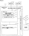
- FIG. 9 is a block diagram illustrating an example of the configuration of the manufacturing device 100 to which this embodiment is applied in which only a portion relating to this embodiment out of the configuration is schematically illustrated. Meanwhile, the manufacturing device 100 may also be equipped with well-known means of computer-aided design.
- the manufacturing device 100 is schematically provided with a control unit 102 such as a CPU that comprehensively controls an entire manufacturing device 100, a communication control interface unit 104 connected to a communication device such as a router (not illustrated) connected to a communication line and the like, an input/output control interface unit 108 connected to an input unit 112 and an output unit 114, and a storage unit 106 which stores various databases, tables and the like, and the respective units are connected so as to be able to communicate via an arbitrary communication path.
- a control unit 102 such as a CPU that comprehensively controls an entire manufacturing device 100
- a communication control interface unit 104 connected to a communication device such as a router (not illustrated) connected to a communication line and the like
- an input/output control interface unit 108 connected to an input unit 112 and an output unit 114
- a storage unit 106 which stores various databases, tables and the like, and the respective units are connected so as to be able to communicate via an arbitrary communication path.
- Various databases and tables (geometric parameter storage unit 106a and the like) stored in the storage unit 106 being storage means such as a fixed disk device stores various programs, tables, files, databases, web pages and the like used for various processes.
- the geometric parameter storage unit 106a is geometric parameter storage means which stores design conditions of the foldable structure and the geometric parameters.
- the geometric parameter storage unit 106a may store deployment diagram data of the foldable structure (for example, a diagram in which a mountain fold line, a valley fold line and the like are written in a plan view).
- the input/output control interface unit 108 controls the input unit 112 and the output unit 114.
- the input unit 112 a keyboard, a mouse, a touch panel and the like may be used.
- the output unit 114 may be a printing machine, a 3D printer, a laser cutter and the like.
- a monitor including a home television, a touch screen monitor and the like
- the like may be used as the output unit 114 as display means.
- the control unit 102 includes an internal memory for storing a control program such as an operating system (OS), a program specifying various procedures and the like, and required data, and performs information processing for executing various processes by the programs and the like.
- the control unit 102 is functionally and conceptually provided with an origami structure generation unit 102a, a tubular structure forming unit 102b, and a structure output unit 102c.
- the origami structure generation unit 102a is foldable structure generating means that generates an equivalent origami structure including two wall surface arrays from the generating surface array that will later become a shared surface array as an example of the foldable structure. Meanwhile, the origami structure generation unit 102a may generate the foldable structure such as the flat-foldable structure and the rigid-foldable structure in addition to the equivalent origami structure.
- the geometric parameters of the foldable structure such as the origami structure, the flat-foldable structure, and the rigid-foldable structure generated by the origami structure generation unit 102a are stored in the geometric parameter storage unit 106a.
- Fig. 10 is a view illustrating an array structure of three surface arrays obtained by extracting the equivalent origami structure from the folding structure in Fig. 6 .
- a lower stage (SA-3) in Fig. 10 is an extraction of the shared surface array, one tubular structure on the upper side and one tubular structure on the lower side from the sandwich structure in Fig. 3 .
- the tubular structures on the upper and lower sides of the shared surface array of the sandwich structure illustrated in Fig. 6 may be defined by a normal direction of the wall surface array which is the array of the surfaces in contact with the shared surface array. Therefore, it is only necessary to consider an array structure in which three arrays of the wall surface array on one side, the shared surface array, and the wall surface array on the other side are connected as in an intermediate stage (SA-2) in Fig. 10 by further simplifying the same. Since only the normal direction of the wall surface array is important, even if this is extended to the opposite side of the shared surface as in an upper stage (SA-1) in Fig.
- a property of the deforming mechanism is maintained, so that the one only the wall surface on one side of which is extended is made a basic array structure for examining the conformity condition to be described below. Also, in a case where the wall surface arrays on both sides self-intersect, the property of the deforming mechanism is maintained even if the array structure without self-intersection is made by appropriately translating the respective surfaces without changing the normal direction. In the array structure thus modeled, there are following three conformity conditions capable of conforming the deforming mechanisms of three quadrangle arrays.
- Fig. 11 is a view illustrating the basic array structure and the tubular structure by a parallel surface group.
- the fold lines formed between the same and the shared surface array also become parallel to each other and the deforming mechanisms of the two tubular structures conform to each other.
- the normal directions of the three types of surface groups are substantially two types, so that this is structurally equivalent to that of the single tubular structure.
- Fig. 12 is a view illustrating the basic array structure and the tubular structure by a mirror symmetric surface group.
- SA-1 of Fig. 12 in a case where the shared surface array is a cylindrical surface (ridge lines connecting the surfaces are parallel to one another), and the wall surface arrays on both sides are mirror symmetric with respect to a plane orthogonal to the cylindrical surface, the deforming mechanisms of the two tubular structures conform to each other.
- the twisting characteristic is reversed due to a mirror symmetric property, and the stiffness to inhibited the non-uniform deformation is imparted.
- the fold line formed by the shared surface array and the wall surface array also becomes mirror symmetric, and the non-uniformity of the fold line is reversed.
- Fig. 13 is a view illustrating the basic array structure and the tubular structure according to a bidirectionally flat-foldable condition.
- an internal angle at each internal vertex of a 3 ⁇ n array structure in which the shared surface array is a free single curved surface in order to satisfy the bidirectionally flat-foldable condition the sum of opposite angles should be 180°, or the opposite angles should be equal and a dihedral angle at the ridge line should not be 0° or 180°.
- the sum of the opposite angles is 180° in a case where the wall surface is extended while maintaining the conformity of the mechanism.
- a smooth curved tubular structure is a structure which may be defined as an envelope surface formed by two pairs of parallel surfaces moving in space (refer to Non-Patent Document 1), and a line on the shared surface array at each position when the curved surface is formed by the parallel surfaces is referred to as the generatrix.
- Fig. 14 is a view illustrating the relationship of the internal angles of the respective surfaces when the conformity conditions 1, 2, and 3 of the deforming mechanism are satisfied from the left, respectively.
- the origami structure generation unit 102a may generate the array structure so as to satisfy the conformity condition 2 of the deforming mechanism to generate the equivalent origami structure.
- the sum of the opposite angles is 180° as for the internal angle at each internal vertex. That is, as illustrated in Fig. 14(c) , an opposite angle of an internal angle A1 is ⁇ -A1, and an opposite angle of an internal angle B1 is ⁇ -B1. Also, an opposite angle of an internal angle A2 is ⁇ -A2, and an opposite angle of an internal angle B2 is ⁇ -B2. Also, as for the other side surface array, an opposite angle of an internal angle ⁇ 1 is ⁇ - ⁇ 1 and an opposite angle of an internal angle ⁇ 1 is ⁇ - ⁇ 1 as illustrated.
- an opposite angle of an internal angle ⁇ 2 is ⁇ - ⁇ 2, and an opposite angle of an internal angle ⁇ 2 is ⁇ - ⁇ 2.
- the opposite angles thereof are A1, B1, A2, B2, ⁇ 1, ⁇ 1, ⁇ 2, and ⁇ 2, respectively, and the sum of the opposite angles is 180°.
- the origami structure generation unit 102a may generate the array structure by determining the internal angle such that the propagation amount of the fold angle through one wall surface array and the propagation amount of the fold angle through the other wall surface array are equal to each other while setting the sum of the opposite angles to 180° as for the internal angle at each internal vertex. Meanwhile, a method of calculating the propagation amount will be described later in detail.
- the origami structure generation unit 102a may generate the equivalent origami structure by generating the array structure including the generating surface array and the two wall surface arrays. Meanwhile, in a case where the two wall surface arrays are generated on the same side with respect to the generating surface array as in SA-1, the origami structure generation unit may extend one of the wall surface arrays so as to penetrate the generating surface array as in SA-2, thereby generating the wall surface arrays on the upper and lower sides of the generating surface array to generate the equivalent origami structure.
- the origami structure generation unit 102a generates a structure duplicated mirror symmetric with respect to an arbitrary plane perpendicular to the cylindrical surface in which an arbitrary trapezoidal array is connected to the generating surface array (shared surface array) being the cylindrical surface to make the same the wall surface array on one side (refer SA-1 in Fig. 12 ).
- the origami structure generation unit 102a may also generate the other wall surface array by extending the duplicated surface array to the opposite side across the generating surface (shared surface) (refer to SA-2 in Fig. 12 ). Even if the extension operation as described above is performed, the property of the structure does not change, so that the conformity of the deforming mechanism is maintained.
- the tubular structure forming unit 102b is tubular structure forming means of forming the tubular structures on both sides of the generating surface being the shared surface on the basis of the equivalent origami structure (combination of the generating surface array and the two wall surface arrays) generated by the origami structure generation unit 102a.
- the tubular structure forming unit 102b may also form the tubular structure of the surface arrays offset in parallel on both sides of the generating surface array and the surface arrays offset in parallel from the respective wall surface arrays (refer to operation from SA-2 to SA-3 in Figs. 10 to 13 described above).
- the tubular structure forming unit 102b may translate the wall surface array in the generatrix direction of the cylindrical surface to copy and connect an upper surface by a surface array parallel to the generating surface, thereby making the tubular structure on one surface as illustrated in SA-2 and SA-3 in Fig. 12 .
- the origami structure generation unit 102a may perform the equivalent operation to the opposite side to obtain the tubular structures on both sides.
- the tubular structure forming unit 102b creates the tubular structure from the generating surface array (shared surface array) and the wall surface array generated by the origami structure generation unit 102a.
- the tubular structure forming unit 102b may offset the generating surface array (shared surface array) by a fixed distance (operation of making a surface equidistant from the surface and reconfiguring a surface array connecting them), or offset the wall surface array by a certain distance, thereby creating two pairs of parallel surface arrays. Then, the tubular structure forming unit 102b may form the tubular structure by connecting them.
- the tubular structure forming unit 102b may also form a cellular structure by forming a plurality of parallel surface arrays on one side of the generating surface (shared surface) by repeatedly executing the offset operation.
- the tubular structure on one side of the shared surface array may be coupled by the equivalent operation as that of well-known aligned-coupling.
- the geometric parameters of the tubular structure formed by the tubular structure forming unit 102b as described above are stored in the geometric parameter storage unit 106a.
- the tubular structure forming unit 102b may adjust a design according to a thickness of the material of the foldable structure to be manufactured. That is, in a case where the material of the foldable structure to be manufactured is thin like paper, the foldability is obvious, but in a case where the thickness of the material is equal to or larger than a predetermined value, it is not possible to bend the same as designed. Therefore, the tubular structure forming unit 102b may adjust the design so that the thickness does not interfere at a portion to be folded and deformed.
- the tubular structure forming unit 102b may adjust the design by using a well-known hinge shift method (refer to U.S. Pat. No. 7,794,019 , Yan Chen, Rui Peng, Zhong You, "Origami of thick panels” Science, 349 (6246), 2015 and the like ), or the well-known volume trim method (refer to Tachi T. "Rigid-Foldable Thick Origami", Origami 5. Fifth International Meeting of Origami Science, Mathematics, and Education, A K Peters/CRC Press 2011, Pages 253 to 263 and the like ).
- the structure output unit 102c is structure output means which manufactures the foldable structure by outputting composite data of the tubular structure formed by the tubular structure forming unit 102b to the output unit 114.
- the structure output unit 102c may print-out the deployment diagram data formed by the tubular structure forming unit 102b and stored in the geometric parameter storage unit 106a to the output unit 114 of the printer.
- the structure output unit 102c may manufacture a foldable three-dimensional structure by outputting foldable structure data formed by the tubular structure forming unit 102b to the output unit 114 as a 3D printer.
- the structure output unit 102c may cut out a deployment diagram shape from a metal plate by the output unit 114 such as a laser cutter.
- the foldable structure may be manufactured by coupling the respective surfaces manually or automatically by an industrial robot or the like.
- the communication control interface unit 104 is a device that performs communication control between the manufacturing device 100 and a network 300 (or a communication device such as a router). That is, the communication control interface unit 104 has a function of communicating data with another external device 200 or a station via a communication line (regardless of whether this is wired or wireless). Meanwhile, the network 300 has a function of mutually connecting a manufacturing device 100 and the external device 200, and is, for example, the Internet or the like.
- the manufacturing device 100 may be connected so as to be able to communicate with the external device 200 that provides various databases such as generating curved surfaces and geometric parameters, an external program such as a program according to the present invention and the like via the network 300. Also, the manufacturing device 100 may be connected to the network 300 so as to be able to communicate via the communication device such as the router and a wired or wireless communication line such as a dedicated line.
- the communication device such as the router and a wired or wireless communication line such as a dedicated line.
- the external device 200 may be mutually connected to the manufacturing device 100 via the network 300, and have a function of providing an external database relating to the data such as the geometric parameters and a website executing an external program and the like such as a program to the user.
- the external device 200 may be configured as a WEB server, an ASP server or the like, and a hardware configuration thereof may include an information processing device such as commercially available workstation, personal computer and the like, and its accessory device.
- each function of the external device 200 is realized by a CPU, a disk device, a memory device, an input device, an output device, a communication control device and the like in the hardware configuration of the external device 200, a program for controlling them and the like.
- Fig. 15 is a flowchart illustrating an example of the process for manufacturing the foldable structure under the conformity condition 2 in the manufacturing device 100 of this embodiment.
- the origami structure generation unit 102a of the manufacturing device 100 first obtains an arbitrary cylindrical surface as the generating surface array (step SB-1).
- the origami structure generation unit 102a may control the user to input a curve or a curvature via the input unit 112, or may obtain a cylindrical surface that approximates the input curvature or curve as the generating surface array.
- a well-known geometric approximation method may also be used to obtain the cylindrical surface approximating the curvature and the curve.
- the origami structure generation unit 102a connects an arbitrary trapezoidal array to the generating surface array formed as the cylindrical surface to make the same the wall surface array on one side and generates a structure duplicated mirror symmetric with respect to an arbitrary plane perpendicular to the cylindrical surface as the wall surface array on the other side (step SB-2). Meanwhile, since the obtained two wall surface arrays are on the same side with respect to the shared surface, the origami structure generation unit 102a extends one of the duplicated wall surface arrays to the opposite side across the shared surface, thereby generating the other wall surface array.
- the tubular structure forming unit 102b translates the wall surface array in a generatrix direction of the cylindrical surface to be duplicated on the basis of the generating surface and the two wall surface arrays generated by the origami structure generation unit 102a, and connects the upper surface by a surface array parallel to the generating surface, thereby generating the tubular structure on one surface (step SB-3). Meanwhile, the origami structure generation unit 102a obtains the tubular structures on both sides by applying the equivalent operation also to the opposite side.
- the structure output unit 102c outputs the deployment diagram data of the foldable structure formed by the tubular structure forming unit 102b to the output unit 114 such as a printing machine, a 3D printer, a laser cutter and the like, thereby manufacturing the foldable structure (step SB-4).
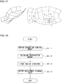
- Fig. 16 is a view illustrating a tetravalent vertex where the sum of the opposite angles is 180°. Meanwhile, for a method of calculating the propagation amount of the fold angle described below, Non-Patent Document 2 may also be referred to.
- a required overall mechanism is that the mechanism of the tetravalent vertex (where the four fold lines are collected) is interlocked without inconsistency.
- the tetravalent vertex already is the mechanism with one degree of freedom. That is, when the angle of one fold line is determined, the angles of the remaining fold lines are also determined. Therefore, the fold angle propagates from one tetravalent vertex to another, and all fold angles are determined.
- k( ⁇ , ⁇ ) is a coefficient representing the amount of propagation of fold angles of adjacent fold lines; since a transmission amount becomes equal in the clockwise direction and in the counterclockwise direction as indicated by joining two arrows in Fig. 14(c) only when the conformity condition 3 is satisfied, this is the constant uniquely determined only with respect to the internal angle of the surface and does not change due to the folding deformation.
- Equation (3) if equation (3) is satisfied in all internal quadrangles, the deforming mechanism is established, and the tangent of half a fold angle pi of all fold lines in the model changes while preserving the ratio of each other.
- This change may be expressed by the following equation using a parameter t: 0 ⁇ ⁇ .
- K1, K2,..., and Kn are constants.
- Fig. 17 is a view illustrating an example of a structure in which surface groups are generated on both sides from the generating surface one after another.
- Fig. 18 is a flowchart illustrating an example of a process for manufacturing the foldable structure under the conformity condition 3 in the manufacturing device 100 of this embodiment.
- the origami structure generation unit 102a of the manufacturing device 100 first obtains an arbitrary curved surface as the generating surface array (step SC-1).
- the origami structure generation unit 102a may control the user to input the curve or the curvature via the input unit 112, or may obtain continuous flat surfaces approximating the input curvature or curve as the generating surface array.
- a well-known geometric approximation method may also be used for obtaining continuous flat surfaces approximating the curvature or the curve.
- the origami structure generation unit 102a determines wall surface arrays w1, w2, ..., and wn one side at a time such that the propagation amount of the fold angle through one wall surface array and the propagation amount of the fold angle through the other wall surface array are equal to each other with respect to the generating surface array being continuous flat surfaces g1, g2, ..., and gn (step SC-2).
- ⁇ 1 may be determined and the angle of the fold line starting from the first vertex may be determined. This intersects with the ridge line between g2 and g3, and ⁇ 2 is determined. Also, ⁇ 2 is determined from equation (5). In this manner, the origami structure generation unit 102a may determine the internal angles of all the fold lines in a chain reaction. Meanwhile, the origami structure generation unit 102a also determines the wall surface structure by the similar process also for the wall surface array on the opposite side.
- the tubular structure forming unit 102b translates the wall surface array in the generatrix direction of the cylindrical surface to duplicate, and connects the upper surface with a surface array parallel to the generating surface, thereby generating the tubular structure of one surface (step SC-3). Meanwhile, the origami structure generation unit 102a obtains the tubular structures on both sides by applying the equivalent operation also to the opposite side.
- the structure output unit 102c outputs the deployment diagram data of the foldable structure formed by the tubular structure forming unit 102b to the output unit 114 such as a printing machine, a 3D printer, and a laser cutter, thereby manufacturing the foldable structure (step SC-4).
- Fig. 19 is a view illustrating a cantilever structure of (a) zipper-coupled structure (zipper), and (b) an aligned-coupled structure (aligned).
- ABAQUS Finite Element Analysis was used for the finite element method simulation.
- a simulation experiment was conducted when extension is 70% of the longest extension.
- height and width of a parallelogram surface forming the tubular structure were set to 1
- the internal angle of the parallelogram was set to 55°
- thickness of the material was set to 0.01 which is one hundredth of the height.
- the Young's modulus of the material was set to 1,000,000.
- all the vertices on a left end were fixed, and a load of 1 was applied to a right end in an X direction (extension and contraction direction), a Y direction, and a Z direction (vertical direction) as indicated by arrows.
- X direction extension and contraction direction
- Y direction extension direction
- Z direction vertical direction
- the units of length and load may be arbitrary set, for example, the length, the force, and the Young's modulus may be represented in cm, N, and N/cm ⁇ 2, respectively. Regardless of unit systems to be used, a relative relationship between the zipper-coupling and the aligned-coupling is maintained.
- Fig. 20 is a graph illustrating change in stiffness with respect to an extension and contraction ratio with the horizontal axis representing the extension and contraction ratio of the tube and the vertical axis representing the stiffness. From the left of the drawing, the stiffness in the X direction, the Y direction, and the Z direction are represented, respectively. As the stiffness, a value obtained by dividing the magnitude of the force by an absolute value of displacement at the end is used. As illustrated in Fig. 20 , the stiffness of the zipper-coupled structure (Zipper) especially in the X direction was confirmed to be high in a wide range of an extension and contraction process.
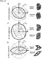
- Fig. 21 is a graph illustrating the stiffness with respect to a direction of force on a YZ plane at 40%, 70%, and 95% extension of the tube, respectively.
- the zipper-coupled structure had little directional dependency and the stiffness of a weak shaft (minimum stiffness) was the maximum.
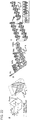
- Fig. 22 is a view illustrating a unit structure and a tubular structure for obtaining an embodiment of another structure.
- the basic tubular structure is formed of the unit structure illustrated in Fig. 22a .
- the unit structure is formed of three variables ⁇ , a, and c. By repeating this N times, the tubular structure is formed. If c is the same, it is possible to couple with a tubular structure with different a and ⁇ . Meanwhile, when the surface is a rigid body, it is a mechanism with one degree of freedom, and a ratio of a length to a length in a flat state is expressed in % as a deployment rate.
- Fig. 23 is a view illustrating transition from the folded state to the deployed state of the foldable structures A, B, and C. Approximate deployment rate is represented in %.
- Fig. 23B assumes the use as a bridge using different tubular structures; this is bidirectionally flat-foldable, and has high out-of-plane stiffness.
- the folding structure illustrated in Fig. 23C has a structure in which ends may be mated to be fixed in a 96.3% deployment state from a state folded flat in one direction. After performing zipper-coupling operation of facing surfaces continuously three times, a next tube is zipper-coupled to the next surface. By performing this operation four times, the structure is such that four side surfaces are closed continuously when being deployed. That is, in a case of transition from the folded state to the deployed state, the tubular structures which are not adjacent to each other so far may be adjacent to be coupled to each other, so that retransition to the folded state may be inhibited.
- Fig. 24 is a view illustrating transition from the folded state to the deployed state of the foldable structures A, B, and C.
- Fig. 24A is a view illustrating the zipper-coupling to a structure having a polygonal cross-section.
- Fig. 24B is a view illustrating an example of the zipper-coupling realized by a panel having a thickness.
- a 80 mm
- c 40 mm
- ⁇ 75°
- N 4.
- Fig. 24C assumes the use as an actuator system of the zipper-coupled tubes of different lengths.
- the end is fixed so as to put liquid inside the long tubular structure.
- an influence of fixing the end disappears due to a non-uniform deformation mode at the end, so that an intermediate part is independently foldable.
- the entire intermediate part exhibits a uniform deformation mode with one degree of freedom with zipper-coupling.
- Fig. 25 is a view illustrating an example of an arch-shaped structure using mirror reversal of the wall surface
- Fig. 26 is a view illustrating a folding process of the arch-shaped structure using the mirror reversal of the wall surface of Fig. 25 .
- this arch-shaped structure is flat-foldable (with flat-foldability).
- Fig. 27 is a view illustrating another example of the arch-shaped structure using mirror reversal of the wall surface
- Fig. 28 is a view illustrating a folding process of the arch-shaped structure using the mirror reversal of the wall surface of Fig. 27 .
- the arch-shaped structure is folded with a width.
- Fig. 29 is a view illustrating an example of a structure using the mirror reversal as a curved sandwich core.
- this curved sandwich core has a curved tubular structure in which the shared surface array and the wall surface arrays are infinitely subdivided and smoothed, so that seven surface arrays are formed of smooth curved surfaces, and it is possible to obtain a foldable structure in which each surface is bent to be deformed and deformed by being folded along the fold line between the surfaces.
- a curved sandwich structure capable of being bent to be deformed may be formed.
- the manufacturing device 100 may perform processing in response to a request from a client terminal (such as the external device 200) and return a processing result to the client terminal.
- a client terminal such as the external device 200
- the illustrated components are functionally conceptual, and it is not necessarily required that they be physically structured as illustrated.
- all or an arbitrary part of a processing function of each device of the manufacturing device 100 may be realized by a central processing unit (CPU) and a program interpreted and executed by the CPU, or may be realized as hardware by wired logic.
- the program is recorded in a non-transitory computer-readable recording medium including a programmed instruction for allowing the computer to execute the method according to the present invention to be described later, and is mechanically read by the manufacturing device 100 as needed. That is, in the storage unit 106 such as the ROM or the hard disk drive (HDD), a computer program for giving instructions to the CPU in cooperation with the operating system (OS) and performing various processes is recorded. This computer program is executed by being loaded into the RAM, and cooperates with the CPU to form a control unit.
- OS operating system
- this computer program may be stored in an application program server connected to the manufacturing device 100 via an arbitrary network 300, and it is also possible to download all or a part thereof as needed.
- the program according to the present invention may be stored in a computer-readable recording medium, or may be formed as a program product.
- the "recording medium” includes an arbitrary "portable physical medium” such as a memory card, a USB memory, an SD card, a flexible disk, a magneto-optical disk, a ROM, an EPROM, an EEPROM, a CD-ROM, an MO, a DVD, and a Blu-ray (registered trademark) Disc.
- the "program” is a data processing method described in an arbitrary language or description method, regardless of the format of source code, binary code and the like.
- the "program” is not necessarily limited to a single program, but this includes that configured in a distributed manner as a plurality of modules or libraries, or that achieving its function in cooperation with a separate program represented by an operating system (OS).
- OS operating system
- well-known configurations and procedures may be used for specific configurations for reading the recording medium, reading procedures, installation procedures after reading or the like in the respective devices described in the embodiments.
- the present invention may be configured as a program product in which a program is recorded in a non-transitory computer-readable recording medium.
- Various databases and the like (geometric parameter storage unit 106a and the like) stored in the storage unit 106 are memory devices such as RAM and ROM, fixed disk devices such as hard disks, and storage means such as flexible disks and optical disks, and store various programs, tables, databases, files for web pages and the like used for various processes and website presentation.
- the manufacturing device 100 and the external device 200 may be configured as an information processing device such as known personal computer, workstation and the like, and may be configured by connecting an arbitrary peripheral device to the information processing device. Also, the manufacturing device 100 and the external device 200 may be realized by mounting software (including programs, data and the like) for realizing the method of the present invention on the information processing device.
- the present invention may provide a foldable structure to which stiffness is imparted so as to inhibit non-uniform extension and contraction even when each surface is formed of a flexible material, a manufacturing method and a manufacturing device of the foldable structure, and a program.
- foldable structure may be used for doors without hinges, roofs, and buildings such as temporary housings. It is also useful as furniture such as chairs, outdoor equipment and the like which may be compactly transported and deployed at a necessary place.
- this since this can transmit force while being flexible, this may also be used as a material for soft robotics engineering.
- this is also useful as an actuator, a morphing blade whose shape changes without using a hinge, an extension mast, a medical material such as a stent and the like.
Landscapes
- Engineering & Computer Science (AREA)
- Architecture (AREA)
- Physics & Mathematics (AREA)
- Electromagnetism (AREA)
- Civil Engineering (AREA)
- Structural Engineering (AREA)
- Toys (AREA)
- Bending Of Plates, Rods, And Pipes (AREA)
Applications Claiming Priority (2)
| Application Number | Priority Date | Filing Date | Title |
|---|---|---|---|
| JP2015160229 | 2015-08-14 | ||
| PCT/JP2016/073806 WO2017030103A1 (fr) | 2015-08-14 | 2016-08-12 | Structure pliable, procédé de fabrication de structure pliable, dispositif de fabrication de structure pliable, et programme |
Publications (3)
| Publication Number | Publication Date |
|---|---|
| EP3336408A1 true EP3336408A1 (fr) | 2018-06-20 |
| EP3336408A4 EP3336408A4 (fr) | 2019-03-20 |
| EP3336408B1 EP3336408B1 (fr) | 2019-10-23 |
Family
ID=58051134
Family Applications (1)
| Application Number | Title | Priority Date | Filing Date |
|---|---|---|---|
| EP16837093.0A Active EP3336408B1 (fr) | 2015-08-14 | 2016-08-12 | Structure pliable, procédé de fabrication de structure pliable, dispositif de fabrication de structure pliable, et programme |
Country Status (5)
| Country | Link |
|---|---|
| US (1) | US10875273B2 (fr) |
| EP (1) | EP3336408B1 (fr) |
| JP (1) | JP6417578B2 (fr) |
| CN (1) | CN107923571B (fr) |
| WO (1) | WO2017030103A1 (fr) |
Families Citing this family (19)
| Publication number | Priority date | Publication date | Assignee | Title |
|---|---|---|---|---|
| USD839452S1 (en) | 2016-06-20 | 2019-01-29 | Dolby Laboratories Licensing, Corporation | Panel |
| US11454475B2 (en) * | 2016-09-07 | 2022-09-27 | Brigham Young University | Deployable origami-inspired barriers |
| AU2017324442B2 (en) * | 2016-09-07 | 2020-09-10 | Brigham Young University | Deployable origami-inspired barriers |
| US11814214B2 (en) * | 2017-05-03 | 2023-11-14 | Difold Inc. | Collapsible article comprising combinations and multiplications of foldable sections |
| USD882832S1 (en) * | 2017-09-12 | 2020-04-28 | Dolby Laboratories Licensing Corporation | Panel |
| JP2020186801A (ja) * | 2019-05-17 | 2020-11-19 | 国立大学法人東北大学 | アクチュエータ |
| US11530621B2 (en) | 2019-10-16 | 2022-12-20 | General Electric Company | Systems and method for use in servicing a machine |
| CN111546367B (zh) * | 2020-06-08 | 2025-01-21 | 鹏城实验室 | 可两向弯曲的折叠臂和捕获设备 |
| CN112208677B (zh) * | 2020-09-30 | 2022-02-01 | 广州大学 | 一种具有变刚度特性的堆叠式折纸结构 |
| CN112458870B (zh) * | 2020-11-12 | 2022-08-30 | 汕头大学 | 一种基于折纸结构的新型可展桥梁结构 |
| CN112743933B (zh) * | 2020-12-02 | 2022-12-27 | 郑州大学 | 一种双层自旋折纸蜂窝夹层吸能材料及其制备方法 |
| CN113638498B (zh) * | 2021-05-31 | 2022-09-02 | 东南大学 | 一种基于广义Miura折纸的双层可折叠膜结构 |
| CN114659408B (zh) * | 2022-02-14 | 2024-04-12 | 东南大学 | 一种基于Kresling折纸的复合抗爆结构及其设计方法 |
| IT202200002732A1 (it) * | 2022-02-15 | 2023-08-15 | Carlo Caltabiano | Metodo per realizzare un materiale per articoli di abbigliamento o arredamento, materiale, ed articolo di abbigliamento o arredamento cosi’ ottenuto |
| CN114654445B (zh) * | 2022-03-02 | 2023-06-02 | 上海工程技术大学 | 一种线驱动的柔性机器人 |
| CN116370166B (zh) * | 2023-04-04 | 2025-07-25 | 合肥综合性国家科学中心人工智能研究院(安徽省人工智能实验室) | 基于变刚度折纸机构的动力型下肢假肢 |
| US12473670B2 (en) | 2023-05-16 | 2025-11-18 | The Hong Kong University Of Science And Technology | Woven quadrilateral mesh origami structures and related functional materials |
| CN117415907B (zh) * | 2023-09-08 | 2026-02-17 | 嘉兴饶稷科技有限公司 | 一种负泊松比三浦折纸结构的氧化锆陶瓷的制作方法 |
| CN119830608B (zh) * | 2025-03-14 | 2025-05-27 | 泉州装备制造研究所 | 一种拉链轻滑度的表征方法及拉链设计参数的确定方法 |
Family Cites Families (11)
| Publication number | Priority date | Publication date | Assignee | Title |
|---|---|---|---|---|
| US3524288A (en) * | 1969-06-23 | 1970-08-18 | Gen Electric | Complex,non-spherical structures |
| US6233880B1 (en) * | 1997-12-03 | 2001-05-22 | Nishimatsu Construction Co., Ltd. | Deployable structure |
| US7794019B2 (en) | 2005-07-08 | 2010-09-14 | Charles Hoberman | Folding structures made of thick hinged sheets |
| US8384613B1 (en) * | 2009-09-08 | 2013-02-26 | The United States Of America As Represented By The Secretary Of The Air Force | Deployable structures with quadrilateral reticulations |
| CN101956426B (zh) * | 2010-04-13 | 2013-04-24 | 天津大学 | 多铰线顶升球面网壳结构及其施工方法 |
| JP2012042044A (ja) * | 2010-08-20 | 2012-03-01 | Koryo Miura | 伸縮性複合セル構造 |
| JP2012116566A (ja) * | 2010-12-02 | 2012-06-21 | Koryo Miura | 折り畳みボックス構造 |
| CN102605861B (zh) * | 2012-03-08 | 2014-04-16 | 东南大学 | 可展索杆穹顶结构 |
| CN102912851B (zh) * | 2012-10-18 | 2014-05-28 | 东南大学 | 一种棱柱型对称可展机构单元 |
| CN103015531B (zh) * | 2012-12-05 | 2014-10-22 | 天津大学 | 具有一个刚性自由度的可折叠管状结构 |
| JP6256867B2 (ja) * | 2013-08-07 | 2018-01-10 | 学校法人明治大学 | 筒状折り畳み構造物の製造方法、筒状折り畳み構造物の製造装置、及び、筒状折り畳み構造物 |
-
2016
- 2016-08-12 WO PCT/JP2016/073806 patent/WO2017030103A1/fr not_active Ceased
- 2016-08-12 CN CN201680047240.4A patent/CN107923571B/zh active Active
- 2016-08-12 EP EP16837093.0A patent/EP3336408B1/fr active Active
- 2016-08-12 JP JP2017535529A patent/JP6417578B2/ja active Active
-
2018
- 2018-02-14 US US15/896,519 patent/US10875273B2/en active Active
Also Published As
| Publication number | Publication date |
|---|---|
| US10875273B2 (en) | 2020-12-29 |
| JP6417578B2 (ja) | 2018-11-07 |
| US20190381755A1 (en) | 2019-12-19 |
| JPWO2017030103A1 (ja) | 2018-04-26 |
| WO2017030103A1 (fr) | 2017-02-23 |
| EP3336408B1 (fr) | 2019-10-23 |
| CN107923571B (zh) | 2020-10-23 |
| EP3336408A4 (fr) | 2019-03-20 |
| CN107923571A (zh) | 2018-04-17 |
Similar Documents
| Publication | Publication Date | Title |
|---|---|---|
| EP3336408B1 (fr) | Structure pliable, procédé de fabrication de structure pliable, dispositif de fabrication de structure pliable, et programme | |
| Lang et al. | A review of thickness-accommodation techniques in origami-inspired engineering | |
| Lang et al. | Rigidly foldable quadrilateral meshes from angle arrays | |
| Zhu et al. | A review on origami simulations: From kinematics, to mechanics, toward multiphysics | |
| Nassar et al. | Curvature, metric and parametrization of origami tessellations: theory and application to the eggbox pattern | |
| Lobontiu et al. | Analytical model of displacement amplification and stiffness optimization for a class of flexure-based compliant mechanisms | |
| Nelson et al. | Facilitating deployable mechanisms and structures via developable lamina emergent arrays | |
| Deng et al. | Synthesis of deployable/foldable single loop mechanisms with revolute joints | |
| Peraza Hernandez et al. | Kinematics of origami structures with smooth folds | |
| Winder et al. | Kinematic representations of pop-up paper mechanisms | |
| Seffen | Compliant shell mechanisms | |
| Hanna et al. | Force–deflection modeling for generalized origami waterbomb-base mechanisms | |
| Lu et al. | A network of type III Bricard linkages | |
| Brown et al. | Approaches for minimizing joints in single-degree-of-freedom origami-based mechanisms | |
| Butler et al. | Folding of thick origami through regionally sandwiched compliant sheets | |
| Yang et al. | Folding miura-ori of uniform thickness with one degree-of-freedom | |
| Pehrson et al. | Load–displacement characterization in three degrees-of-freedom for general lamina emergent torsion arrays | |
| Alfattani et al. | A lamina-emergent frustum using a bistable collapsible compliant mechanism | |
| Tsiamis et al. | Algorithmic design and analysis of architectural origami | |
| Kwok | Geometry-based thick origami simulation | |
| Yamaguchi et al. | Post-fabrication tuning of origami-inspired mechanical metamaterials based on Tachi-Miura Polyhedron | |
| Alfattani et al. | Shape-morphing using bistable triangles with dwell-enhanced stability | |
| Tachi | One-DOF rigid foldable structures from space curves | |
| Beatini et al. | Shapes of Miura mesh mechanism with mobility one | |
| Liu et al. | Reconfigurable thick-panel structures based on a stacked origami tube |
Legal Events
| Date | Code | Title | Description |
|---|---|---|---|
| STAA | Information on the status of an ep patent application or granted ep patent |
Free format text: STATUS: THE INTERNATIONAL PUBLICATION HAS BEEN MADE |
|
| PUAI | Public reference made under article 153(3) epc to a published international application that has entered the european phase |
Free format text: ORIGINAL CODE: 0009012 |
|
| STAA | Information on the status of an ep patent application or granted ep patent |
Free format text: STATUS: REQUEST FOR EXAMINATION WAS MADE |
|
| 17P | Request for examination filed |
Effective date: 20180227 |
|
| AK | Designated contracting states |
Kind code of ref document: A1 Designated state(s): AL AT BE BG CH CY CZ DE DK EE ES FI FR GB GR HR HU IE IS IT LI LT LU LV MC MK MT NL NO PL PT RO RS SE SI SK SM TR |
|
| AX | Request for extension of the european patent |
Extension state: BA ME |
|
| DAV | Request for validation of the european patent (deleted) | ||
| DAX | Request for extension of the european patent (deleted) | ||
| RAP1 | Party data changed (applicant data changed or rights of an application transferred) |
Owner name: JAPAN SCIENCE AND TECHNOLOGY AGENCY Owner name: THE BOARD OF TRUSTEES OF THE UNIVERSITY OF ILLINOI |
|
| A4 | Supplementary search report drawn up and despatched |
Effective date: 20190214 |
|
| RIC1 | Information provided on ipc code assigned before grant |
Ipc: B31D 5/04 20170101ALI20190208BHEP Ipc: F16S 1/04 20060101AFI20190208BHEP Ipc: E04B 1/343 20060101ALI20190208BHEP |
|
| RIC1 | Information provided on ipc code assigned before grant |
Ipc: B31D 5/04 20170101ALI20190423BHEP Ipc: E04B 1/343 20060101ALI20190423BHEP Ipc: F16S 1/04 20060101AFI20190423BHEP |
|
| GRAP | Despatch of communication of intention to grant a patent |
Free format text: ORIGINAL CODE: EPIDOSNIGR1 |
|
| STAA | Information on the status of an ep patent application or granted ep patent |
Free format text: STATUS: GRANT OF PATENT IS INTENDED |
|
| INTG | Intention to grant announced |
Effective date: 20190611 |
|
| GRAS | Grant fee paid |
Free format text: ORIGINAL CODE: EPIDOSNIGR3 |
|
| GRAA | (expected) grant |
Free format text: ORIGINAL CODE: 0009210 |
|
| STAA | Information on the status of an ep patent application or granted ep patent |
Free format text: STATUS: THE PATENT HAS BEEN GRANTED |
|
| AK | Designated contracting states |
Kind code of ref document: B1 Designated state(s): AL AT BE BG CH CY CZ DE DK EE ES FI FR GB GR HR HU IE IS IT LI LT LU LV MC MK MT NL NO PL PT RO RS SE SI SK SM TR |
|
| REG | Reference to a national code |
Ref country code: GB Ref legal event code: FG4D |
|
| REG | Reference to a national code |
Ref country code: CH Ref legal event code: EP |
|
| REG | Reference to a national code |
Ref country code: IE Ref legal event code: FG4D |
|
| REG | Reference to a national code |
Ref country code: DE Ref legal event code: R096 Ref document number: 602016023112 Country of ref document: DE |
|
| REG | Reference to a national code |
Ref country code: AT Ref legal event code: REF Ref document number: 1194041 Country of ref document: AT Kind code of ref document: T Effective date: 20191115 |
|
| REG | Reference to a national code |
Ref country code: NL Ref legal event code: MP Effective date: 20191023 |
|
| REG | Reference to a national code |
Ref country code: LT Ref legal event code: MG4D |
|
| PG25 | Lapsed in a contracting state [announced via postgrant information from national office to epo] |
Ref country code: SE Free format text: LAPSE BECAUSE OF FAILURE TO SUBMIT A TRANSLATION OF THE DESCRIPTION OR TO PAY THE FEE WITHIN THE PRESCRIBED TIME-LIMIT Effective date: 20191023 Ref country code: PT Free format text: LAPSE BECAUSE OF FAILURE TO SUBMIT A TRANSLATION OF THE DESCRIPTION OR TO PAY THE FEE WITHIN THE PRESCRIBED TIME-LIMIT Effective date: 20200224 Ref country code: LV Free format text: LAPSE BECAUSE OF FAILURE TO SUBMIT A TRANSLATION OF THE DESCRIPTION OR TO PAY THE FEE WITHIN THE PRESCRIBED TIME-LIMIT Effective date: 20191023 Ref country code: NO Free format text: LAPSE BECAUSE OF FAILURE TO SUBMIT A TRANSLATION OF THE DESCRIPTION OR TO PAY THE FEE WITHIN THE PRESCRIBED TIME-LIMIT Effective date: 20200123 Ref country code: GR Free format text: LAPSE BECAUSE OF FAILURE TO SUBMIT A TRANSLATION OF THE DESCRIPTION OR TO PAY THE FEE WITHIN THE PRESCRIBED TIME-LIMIT Effective date: 20200124 Ref country code: BG Free format text: LAPSE BECAUSE OF FAILURE TO SUBMIT A TRANSLATION OF THE DESCRIPTION OR TO PAY THE FEE WITHIN THE PRESCRIBED TIME-LIMIT Effective date: 20200123 Ref country code: FI Free format text: LAPSE BECAUSE OF FAILURE TO SUBMIT A TRANSLATION OF THE DESCRIPTION OR TO PAY THE FEE WITHIN THE PRESCRIBED TIME-LIMIT Effective date: 20191023 Ref country code: LT Free format text: LAPSE BECAUSE OF FAILURE TO SUBMIT A TRANSLATION OF THE DESCRIPTION OR TO PAY THE FEE WITHIN THE PRESCRIBED TIME-LIMIT Effective date: 20191023 Ref country code: PL Free format text: LAPSE BECAUSE OF FAILURE TO SUBMIT A TRANSLATION OF THE DESCRIPTION OR TO PAY THE FEE WITHIN THE PRESCRIBED TIME-LIMIT Effective date: 20191023 Ref country code: NL Free format text: LAPSE BECAUSE OF FAILURE TO SUBMIT A TRANSLATION OF THE DESCRIPTION OR TO PAY THE FEE WITHIN THE PRESCRIBED TIME-LIMIT Effective date: 20191023 |
|
| PG25 | Lapsed in a contracting state [announced via postgrant information from national office to epo] |
Ref country code: HR Free format text: LAPSE BECAUSE OF FAILURE TO SUBMIT A TRANSLATION OF THE DESCRIPTION OR TO PAY THE FEE WITHIN THE PRESCRIBED TIME-LIMIT Effective date: 20191023 Ref country code: IS Free format text: LAPSE BECAUSE OF FAILURE TO SUBMIT A TRANSLATION OF THE DESCRIPTION OR TO PAY THE FEE WITHIN THE PRESCRIBED TIME-LIMIT Effective date: 20200224 Ref country code: RS Free format text: LAPSE BECAUSE OF FAILURE TO SUBMIT A TRANSLATION OF THE DESCRIPTION OR TO PAY THE FEE WITHIN THE PRESCRIBED TIME-LIMIT Effective date: 20191023 |
|
| PG25 | Lapsed in a contracting state [announced via postgrant information from national office to epo] |
Ref country code: AL Free format text: LAPSE BECAUSE OF FAILURE TO SUBMIT A TRANSLATION OF THE DESCRIPTION OR TO PAY THE FEE WITHIN THE PRESCRIBED TIME-LIMIT Effective date: 20191023 |
|
| REG | Reference to a national code |
Ref country code: DE Ref legal event code: R097 Ref document number: 602016023112 Country of ref document: DE |
|
| PG2D | Information on lapse in contracting state deleted |
Ref country code: IS |
|
| PG25 | Lapsed in a contracting state [announced via postgrant information from national office to epo] |
Ref country code: RO Free format text: LAPSE BECAUSE OF FAILURE TO SUBMIT A TRANSLATION OF THE DESCRIPTION OR TO PAY THE FEE WITHIN THE PRESCRIBED TIME-LIMIT Effective date: 20191023 Ref country code: CZ Free format text: LAPSE BECAUSE OF FAILURE TO SUBMIT A TRANSLATION OF THE DESCRIPTION OR TO PAY THE FEE WITHIN THE PRESCRIBED TIME-LIMIT Effective date: 20191023 Ref country code: DK Free format text: LAPSE BECAUSE OF FAILURE TO SUBMIT A TRANSLATION OF THE DESCRIPTION OR TO PAY THE FEE WITHIN THE PRESCRIBED TIME-LIMIT Effective date: 20191023 Ref country code: EE Free format text: LAPSE BECAUSE OF FAILURE TO SUBMIT A TRANSLATION OF THE DESCRIPTION OR TO PAY THE FEE WITHIN THE PRESCRIBED TIME-LIMIT Effective date: 20191023 Ref country code: ES Free format text: LAPSE BECAUSE OF FAILURE TO SUBMIT A TRANSLATION OF THE DESCRIPTION OR TO PAY THE FEE WITHIN THE PRESCRIBED TIME-LIMIT Effective date: 20191023 Ref country code: IS Free format text: LAPSE BECAUSE OF FAILURE TO SUBMIT A TRANSLATION OF THE DESCRIPTION OR TO PAY THE FEE WITHIN THE PRESCRIBED TIME-LIMIT Effective date: 20200223 |
|
| REG | Reference to a national code |
Ref country code: AT Ref legal event code: MK05 Ref document number: 1194041 Country of ref document: AT Kind code of ref document: T Effective date: 20191023 |
|
| PLBE | No opposition filed within time limit |
Free format text: ORIGINAL CODE: 0009261 |
|
| STAA | Information on the status of an ep patent application or granted ep patent |
Free format text: STATUS: NO OPPOSITION FILED WITHIN TIME LIMIT |
|
| PG25 | Lapsed in a contracting state [announced via postgrant information from national office to epo] |
Ref country code: SM Free format text: LAPSE BECAUSE OF FAILURE TO SUBMIT A TRANSLATION OF THE DESCRIPTION OR TO PAY THE FEE WITHIN THE PRESCRIBED TIME-LIMIT Effective date: 20191023 Ref country code: IT Free format text: LAPSE BECAUSE OF FAILURE TO SUBMIT A TRANSLATION OF THE DESCRIPTION OR TO PAY THE FEE WITHIN THE PRESCRIBED TIME-LIMIT Effective date: 20191023 Ref country code: SK Free format text: LAPSE BECAUSE OF FAILURE TO SUBMIT A TRANSLATION OF THE DESCRIPTION OR TO PAY THE FEE WITHIN THE PRESCRIBED TIME-LIMIT Effective date: 20191023 |
|
| 26N | No opposition filed |
Effective date: 20200724 |
|
| PG25 | Lapsed in a contracting state [announced via postgrant information from national office to epo] |
Ref country code: AT Free format text: LAPSE BECAUSE OF FAILURE TO SUBMIT A TRANSLATION OF THE DESCRIPTION OR TO PAY THE FEE WITHIN THE PRESCRIBED TIME-LIMIT Effective date: 20191023 Ref country code: SI Free format text: LAPSE BECAUSE OF FAILURE TO SUBMIT A TRANSLATION OF THE DESCRIPTION OR TO PAY THE FEE WITHIN THE PRESCRIBED TIME-LIMIT Effective date: 20191023 |
|
| PG25 | Lapsed in a contracting state [announced via postgrant information from national office to epo] |
Ref country code: MC Free format text: LAPSE BECAUSE OF FAILURE TO SUBMIT A TRANSLATION OF THE DESCRIPTION OR TO PAY THE FEE WITHIN THE PRESCRIBED TIME-LIMIT Effective date: 20191023 |
|
| REG | Reference to a national code |
Ref country code: CH Ref legal event code: PL |
|
| PG25 | Lapsed in a contracting state [announced via postgrant information from national office to epo] |
Ref country code: CH Free format text: LAPSE BECAUSE OF NON-PAYMENT OF DUE FEES Effective date: 20200831 Ref country code: LI Free format text: LAPSE BECAUSE OF NON-PAYMENT OF DUE FEES Effective date: 20200831 Ref country code: LU Free format text: LAPSE BECAUSE OF NON-PAYMENT OF DUE FEES Effective date: 20200812 |
|
| REG | Reference to a national code |
Ref country code: BE Ref legal event code: MM Effective date: 20200831 |
|
| PG25 | Lapsed in a contracting state [announced via postgrant information from national office to epo] |
Ref country code: FR Free format text: LAPSE BECAUSE OF NON-PAYMENT OF DUE FEES Effective date: 20200831 |
|
| PG25 | Lapsed in a contracting state [announced via postgrant information from national office to epo] |
Ref country code: IE Free format text: LAPSE BECAUSE OF NON-PAYMENT OF DUE FEES Effective date: 20200812 Ref country code: BE Free format text: LAPSE BECAUSE OF NON-PAYMENT OF DUE FEES Effective date: 20200831 |
|
| PG25 | Lapsed in a contracting state [announced via postgrant information from national office to epo] |
Ref country code: TR Free format text: LAPSE BECAUSE OF FAILURE TO SUBMIT A TRANSLATION OF THE DESCRIPTION OR TO PAY THE FEE WITHIN THE PRESCRIBED TIME-LIMIT Effective date: 20191023 Ref country code: MT Free format text: LAPSE BECAUSE OF FAILURE TO SUBMIT A TRANSLATION OF THE DESCRIPTION OR TO PAY THE FEE WITHIN THE PRESCRIBED TIME-LIMIT Effective date: 20191023 Ref country code: CY Free format text: LAPSE BECAUSE OF FAILURE TO SUBMIT A TRANSLATION OF THE DESCRIPTION OR TO PAY THE FEE WITHIN THE PRESCRIBED TIME-LIMIT Effective date: 20191023 |
|
| PG25 | Lapsed in a contracting state [announced via postgrant information from national office to epo] |
Ref country code: MK Free format text: LAPSE BECAUSE OF FAILURE TO SUBMIT A TRANSLATION OF THE DESCRIPTION OR TO PAY THE FEE WITHIN THE PRESCRIBED TIME-LIMIT Effective date: 20191023 |
|
| PGFP | Annual fee paid to national office [announced via postgrant information from national office to epo] |
Ref country code: DE Payment date: 20250707 Year of fee payment: 10 |
|
| PGFP | Annual fee paid to national office [announced via postgrant information from national office to epo] |
Ref country code: GB Payment date: 20250707 Year of fee payment: 10 |