EP3336417B1 - Système d'éclairage visible et par uv - Google Patents
Système d'éclairage visible et par uv Download PDFInfo
- Publication number
- EP3336417B1 EP3336417B1 EP17205356.3A EP17205356A EP3336417B1 EP 3336417 B1 EP3336417 B1 EP 3336417B1 EP 17205356 A EP17205356 A EP 17205356A EP 3336417 B1 EP3336417 B1 EP 3336417B1
- Authority
- EP
- European Patent Office
- Prior art keywords
- leds
- light
- exit window
- visible light
- lighting system
- Prior art date
- Legal status (The legal status is an assumption and is not a legal conclusion. Google has not performed a legal analysis and makes no representation as to the accuracy of the status listed.)
- Active
Links
Images



Classifications
-
- F—MECHANICAL ENGINEERING; LIGHTING; HEATING; WEAPONS; BLASTING
- F21—LIGHTING
- F21S—NON-PORTABLE LIGHTING DEVICES; SYSTEMS THEREOF; VEHICLE LIGHTING DEVICES SPECIALLY ADAPTED FOR VEHICLE EXTERIORS
- F21S8/00—Lighting devices intended for fixed installation
-
- F—MECHANICAL ENGINEERING; LIGHTING; HEATING; WEAPONS; BLASTING
- F21—LIGHTING
- F21K—NON-ELECTRIC LIGHT SOURCES USING LUMINESCENCE; LIGHT SOURCES USING ELECTROCHEMILUMINESCENCE; LIGHT SOURCES USING CHARGES OF COMBUSTIBLE MATERIAL; LIGHT SOURCES USING SEMICONDUCTOR DEVICES AS LIGHT-GENERATING ELEMENTS; LIGHT SOURCES NOT OTHERWISE PROVIDED FOR
- F21K9/00—Light sources using semiconductor devices as light-generating elements, e.g. using light-emitting diodes [LED] or lasers
- F21K9/20—Light sources comprising attachment means
- F21K9/23—Retrofit light sources for lighting devices with a single fitting for each light source, e.g. for substitution of incandescent lamps with bayonet or threaded fittings
- F21K9/237—Details of housings or cases, i.e. the parts between the light-generating element and the bases; Arrangement of components within housings or cases
-
- A—HUMAN NECESSITIES
- A61—MEDICAL OR VETERINARY SCIENCE; HYGIENE
- A61N—ELECTROTHERAPY; MAGNETOTHERAPY; RADIATION THERAPY; ULTRASOUND THERAPY
- A61N5/00—Radiation therapy
- A61N5/06—Radiation therapy using light
- A61N5/0613—Apparatus adapted for a specific treatment
- A61N5/0614—Tanning
-
- A—HUMAN NECESSITIES
- A61—MEDICAL OR VETERINARY SCIENCE; HYGIENE
- A61N—ELECTROTHERAPY; MAGNETOTHERAPY; RADIATION THERAPY; ULTRASOUND THERAPY
- A61N5/00—Radiation therapy
- A61N5/06—Radiation therapy using light
- A61N5/0613—Apparatus adapted for a specific treatment
- A61N5/0616—Skin treatment other than tanning
-
- A—HUMAN NECESSITIES
- A61—MEDICAL OR VETERINARY SCIENCE; HYGIENE
- A61N—ELECTROTHERAPY; MAGNETOTHERAPY; RADIATION THERAPY; ULTRASOUND THERAPY
- A61N5/00—Radiation therapy
- A61N5/06—Radiation therapy using light
- A61N5/0613—Apparatus adapted for a specific treatment
- A61N5/0624—Apparatus adapted for a specific treatment for eliminating microbes, germs, bacteria on or in the body
-
- F—MECHANICAL ENGINEERING; LIGHTING; HEATING; WEAPONS; BLASTING
- F21—LIGHTING
- F21V—FUNCTIONAL FEATURES OR DETAILS OF LIGHTING DEVICES OR SYSTEMS THEREOF; STRUCTURAL COMBINATIONS OF LIGHTING DEVICES WITH OTHER ARTICLES, NOT OTHERWISE PROVIDED FOR
- F21V19/00—Fastening of light sources or lamp holders
- F21V19/001—Fastening of light sources or lamp holders the light sources being semiconductors devices, e.g. LEDs
-
- F—MECHANICAL ENGINEERING; LIGHTING; HEATING; WEAPONS; BLASTING
- F21—LIGHTING
- F21V—FUNCTIONAL FEATURES OR DETAILS OF LIGHTING DEVICES OR SYSTEMS THEREOF; STRUCTURAL COMBINATIONS OF LIGHTING DEVICES WITH OTHER ARTICLES, NOT OTHERWISE PROVIDED FOR
- F21V3/00—Globes; Bowls; Cover glasses
- F21V3/04—Globes; Bowls; Cover glasses characterised by materials, surface treatments or coatings
- F21V3/049—Patterns or structured surfaces for diffusing light, e.g. frosted surfaces
-
- F—MECHANICAL ENGINEERING; LIGHTING; HEATING; WEAPONS; BLASTING
- F21—LIGHTING
- F21V—FUNCTIONAL FEATURES OR DETAILS OF LIGHTING DEVICES OR SYSTEMS THEREOF; STRUCTURAL COMBINATIONS OF LIGHTING DEVICES WITH OTHER ARTICLES, NOT OTHERWISE PROVIDED FOR
- F21V33/00—Structural combinations of lighting devices with other articles, not otherwise provided for
- F21V33/0064—Health, life-saving or fire-fighting equipment
-
- F—MECHANICAL ENGINEERING; LIGHTING; HEATING; WEAPONS; BLASTING
- F21—LIGHTING
- F21V—FUNCTIONAL FEATURES OR DETAILS OF LIGHTING DEVICES OR SYSTEMS THEREOF; STRUCTURAL COMBINATIONS OF LIGHTING DEVICES WITH OTHER ARTICLES, NOT OTHERWISE PROVIDED FOR
- F21V7/00—Reflectors for light sources
- F21V7/0008—Reflectors for light sources providing for indirect lighting
- F21V7/0016—Reflectors for light sources providing for indirect lighting on lighting devices that also provide for direct lighting, e.g. by means of independent light sources, by splitting of the light beam, by switching between both lighting modes
-
- F—MECHANICAL ENGINEERING; LIGHTING; HEATING; WEAPONS; BLASTING
- F21—LIGHTING
- F21V—FUNCTIONAL FEATURES OR DETAILS OF LIGHTING DEVICES OR SYSTEMS THEREOF; STRUCTURAL COMBINATIONS OF LIGHTING DEVICES WITH OTHER ARTICLES, NOT OTHERWISE PROVIDED FOR
- F21V7/00—Reflectors for light sources
- F21V7/04—Optical design
- F21V7/06—Optical design with parabolic curvature
-
- F—MECHANICAL ENGINEERING; LIGHTING; HEATING; WEAPONS; BLASTING
- F21—LIGHTING
- F21V—FUNCTIONAL FEATURES OR DETAILS OF LIGHTING DEVICES OR SYSTEMS THEREOF; STRUCTURAL COMBINATIONS OF LIGHTING DEVICES WITH OTHER ARTICLES, NOT OTHERWISE PROVIDED FOR
- F21V7/00—Reflectors for light sources
- F21V7/10—Construction
-
- A—HUMAN NECESSITIES
- A61—MEDICAL OR VETERINARY SCIENCE; HYGIENE
- A61N—ELECTROTHERAPY; MAGNETOTHERAPY; RADIATION THERAPY; ULTRASOUND THERAPY
- A61N5/00—Radiation therapy
- A61N5/06—Radiation therapy using light
- A61N5/0613—Apparatus adapted for a specific treatment
- A61N5/0614—Tanning
- A61N2005/0615—Tanning using UV light sources having a specific spectrum
-
- A—HUMAN NECESSITIES
- A61—MEDICAL OR VETERINARY SCIENCE; HYGIENE
- A61N—ELECTROTHERAPY; MAGNETOTHERAPY; RADIATION THERAPY; ULTRASOUND THERAPY
- A61N5/00—Radiation therapy
- A61N5/06—Radiation therapy using light
- A61N2005/0658—Radiation therapy using light characterised by the wavelength of light used
- A61N2005/0661—Radiation therapy using light characterised by the wavelength of light used ultraviolet
-
- A—HUMAN NECESSITIES
- A61—MEDICAL OR VETERINARY SCIENCE; HYGIENE
- A61N—ELECTROTHERAPY; MAGNETOTHERAPY; RADIATION THERAPY; ULTRASOUND THERAPY
- A61N5/00—Radiation therapy
- A61N5/06—Radiation therapy using light
- A61N2005/0658—Radiation therapy using light characterised by the wavelength of light used
- A61N2005/0662—Visible light
- A61N2005/0663—Coloured light
-
- A—HUMAN NECESSITIES
- A61—MEDICAL OR VETERINARY SCIENCE; HYGIENE
- A61N—ELECTROTHERAPY; MAGNETOTHERAPY; RADIATION THERAPY; ULTRASOUND THERAPY
- A61N5/00—Radiation therapy
- A61N5/06—Radiation therapy using light
- A61N2005/0664—Details
- A61N2005/0665—Reflectors
- A61N2005/0666—Reflectors for redirecting light to the treatment area
-
- F—MECHANICAL ENGINEERING; LIGHTING; HEATING; WEAPONS; BLASTING
- F21—LIGHTING
- F21K—NON-ELECTRIC LIGHT SOURCES USING LUMINESCENCE; LIGHT SOURCES USING ELECTROCHEMILUMINESCENCE; LIGHT SOURCES USING CHARGES OF COMBUSTIBLE MATERIAL; LIGHT SOURCES USING SEMICONDUCTOR DEVICES AS LIGHT-GENERATING ELEMENTS; LIGHT SOURCES NOT OTHERWISE PROVIDED FOR
- F21K9/00—Light sources using semiconductor devices as light-generating elements, e.g. using light-emitting diodes [LED] or lasers
- F21K9/60—Optical arrangements integrated in the light source, e.g. for improving the colour rendering index or the light extraction
- F21K9/62—Optical arrangements integrated in the light source, e.g. for improving the colour rendering index or the light extraction using mixing chambers, e.g. housings with reflective walls
-
- F—MECHANICAL ENGINEERING; LIGHTING; HEATING; WEAPONS; BLASTING
- F21—LIGHTING
- F21V—FUNCTIONAL FEATURES OR DETAILS OF LIGHTING DEVICES OR SYSTEMS THEREOF; STRUCTURAL COMBINATIONS OF LIGHTING DEVICES WITH OTHER ARTICLES, NOT OTHERWISE PROVIDED FOR
- F21V7/00—Reflectors for light sources
- F21V7/0008—Reflectors for light sources providing for indirect lighting
-
- F—MECHANICAL ENGINEERING; LIGHTING; HEATING; WEAPONS; BLASTING
- F21—LIGHTING
- F21V—FUNCTIONAL FEATURES OR DETAILS OF LIGHTING DEVICES OR SYSTEMS THEREOF; STRUCTURAL COMBINATIONS OF LIGHTING DEVICES WITH OTHER ARTICLES, NOT OTHERWISE PROVIDED FOR
- F21V7/00—Reflectors for light sources
- F21V7/22—Reflectors for light sources characterised by materials, surface treatments or coatings, e.g. dichroic reflectors
-
- F—MECHANICAL ENGINEERING; LIGHTING; HEATING; WEAPONS; BLASTING
- F21—LIGHTING
- F21Y—INDEXING SCHEME ASSOCIATED WITH SUBCLASSES F21K, F21L, F21S and F21V, RELATING TO THE FORM OR THE KIND OF THE LIGHT SOURCES OR OF THE COLOUR OF THE LIGHT EMITTED
- F21Y2113/00—Combination of light sources
- F21Y2113/10—Combination of light sources of different colours
- F21Y2113/13—Combination of light sources of different colours comprising an assembly of point-like light sources
-
- F—MECHANICAL ENGINEERING; LIGHTING; HEATING; WEAPONS; BLASTING
- F21—LIGHTING
- F21Y—INDEXING SCHEME ASSOCIATED WITH SUBCLASSES F21K, F21L, F21S and F21V, RELATING TO THE FORM OR THE KIND OF THE LIGHT SOURCES OR OF THE COLOUR OF THE LIGHT EMITTED
- F21Y2113/00—Combination of light sources
- F21Y2113/30—Combination of light sources of visible and non-visible spectrum
-
- F—MECHANICAL ENGINEERING; LIGHTING; HEATING; WEAPONS; BLASTING
- F21—LIGHTING
- F21Y—INDEXING SCHEME ASSOCIATED WITH SUBCLASSES F21K, F21L, F21S and F21V, RELATING TO THE FORM OR THE KIND OF THE LIGHT SOURCES OR OF THE COLOUR OF THE LIGHT EMITTED
- F21Y2115/00—Light-generating elements of semiconductor light sources
- F21Y2115/10—Light-emitting diodes [LED]
Definitions
- This invention relates to lighting systems, in particular for providing visible light as well as UV light, which enables the synthesis in the human body of vitamin D.
- White light sources can produce high quality light with a color rendering index above 90 with very high efficiencies. In general, compared with natural sunlight, such light sources do not have certain parts of the spectrum, such as the UV part of the electromagnetic spectrum.
- UV LEDs for this purpose, it is possible to introduce UV LEDs in combination with white LEDs and also colored light. Furthermore, the use of UV LEDs has also been proposed for producing both white light and also colored light.
- WO-2008/135927 discloses a solid state lighting device comprising a plurality of LEDs, which may for example, comprise UV LEDs.
- US-2010/327745 discloses a light assembly with a lamp base, a housing, and a cover.
- the light assembly further has a substrate or circuit board for supporting solid state light sources that may generate the same wavelength of light or different wavelengths of light. Examples of suitable wavelengths include ultraviolet or blue.
- Low intensity UV light may also be used for other applications such as for skin tanning, insect attraction, skin treatment, disinfection, etc.
- systems which provide UV light as well as visible light have applications other than for emulating natural daylight.
- UV light tends to degrade many of the polymers which are used in current lighting applications, for example in a lighting diffuser.
- a lighting system comprising:
- the housing defines a mixing chamber having a top part and a bottom part.
- the mixing chamber comprises one or more side wall portions and a top wall portion which forms the top part.
- the light exit window is provided at the bottom part.
- the UV LEDs are provided at the top part facing the light exit window.
- the visible light LEDs are mounted (i) on a rim around the light exit window facing the top part, directly or at an angle, (ii) on the one or more side wall portions facing across the mixing chamber, or (iii) at the top part facing in the direction of the light exit window, the reflector arrangement comprising reflector portions over the visible light LEDs to block the light path to the light exit window.
- light is used broadly to refer to the full electromagnetic spectrum, i.e. visible and UV light.
- light exit window should for example be understood accordingly.
- This system provides the output of UV LEDs directly to a light exit window of the lighting system, whereas visible light LEDs deliver their output after reflection.
- This reflection can thus be used to provide desired beam shaping or diffusion so that beam shaping components are not needed at the exit window. In this way, UV deterioration of beam shaping components is avoided.
- the reflector arrangement defines a light mixing chamber particularly if diffuse reflections are provided or it defines a more controlled a reflection profile particularly if specular reflections are provided.
- no diffuser is used at the light exit window, as would normally be used in order to hide spottiness. Instead, the output of the visible light LEDs is indirectly reflected to the outside.
- the system may further comprise a UV beam shaping arrangement for shaping the output of the UV LEDs. This is used to ensure that all, or nearly all of the UV LED output passes to the light exit window and thus does not cause deterioration of other components.
- the UV light is prevented from reaching the UV sensitive parts of the light arrangement such as the visible light LEDs or the polymer materials of the reflector arrangement.
- the UV LEDs thus provide direct lighting.
- the beam shaping arrangement is insensitive to UV light, and may for example comprise a metallic shroud around each UV LED or around sets of UV LEDs.
- the beam shaping arrangement may comprise a shaped part of the support structure. This provides a more integrated design with fewer components.
- the beam shaping arrangement is for example adapted to direct at least 80% of the output of the UV LEDs directly to the exit window, for example at least 85%, for example at least 90%.
- At most 20% of the visible light output from the visible light LEDs may directly reach the light exit window, for example at most 15%, for example at most 10%.
- some direct light output from the visible light LEDs can be allowed, with the reflected light still providing the desired shielding of the visible appearance of the LEDs.
- a small proportion (i.e. intensity) of the UV output may not directly reach the light exit window, as long as that proportion has a sufficiently low intensity to avoid damage to the materials on which that UV output is incident.
- the system is designed so that there is no direct path from the visible light LEDs to the light exit window and so that all UV output is directed to the light exit window.
- the housing defines a mixing chamber, with the UV LEDs at a top part and the light exit window at a bottom part.
- the UV LEDs then simply deliver a downward UV output through the light exit window.
- the visible light LEDs face into the mixing chamber.
- the visible light LEDs are mounted on a rim around the light exit window facing the top part, directly or at an angle. Thus, they face generally upwardly if the system is mounted with the light exit window facing downwardly.
- the mixing chamber comprises one or more side wall portions and a top wall portion which forms the top part, wherein the visible light LEDs are mounted on the one or more side wall portions facing across the mixing chamber.
- the visible light LEDs face sideways.
- the visible light LEDs are at the top part facing in the direction of the light exit window, and the reflector arrangement comprises reflector portions over the visible light LEDs to block the light path to the light exit window.
- the reflector arrangement comprises reflector portions over the visible light LEDs to block the light path to the light exit window.
- all of the LEDs can be mounted on the same surface facing the same (i.e. parallel) direction. The direct light path from the visible LEDs is however blocked by reflector portions. This may be easier to manufacture.
- the light exit window may comprise an empty opening formed in the housing. Thus, the UV output does not pass through any intermediate components at all.
- the light exit window may have a solid transparent UV-resistant closure. This can protect the internal components of the lighting system.
- the UV LEDs for example comprise UV-B LEDs and the visible light LEDs for example comprise LEDs for delivering white light, such as white LEDs or RGB LED arrangements controllable to deliver a white light output.
- the lighting system may comprise an LED lamp (reflector lamp or tubular lamp) or an LED luminaire.
- the invention provides a lighting system which combines an arrangement of UV LEDs which face a light exit window and an arrangement of visible light LEDs which face a reflector arrangement.
- the reflection can be used to provide desired beam shaping or diffusion so that beam shaping components are not needed at the exit window. In this way, UV deterioration of beam shaping components is avoided.
- Figure 1 shows a lighting system for providing visible and UV light into an area to be illuminated.
- the system comprises a housing 10 which comprises a support structure on which LEDs can be mounted and a light exit window 12.
- the support structure in this example is an integral part of the housing, and comprises regions 14 of the housing.
- An arrangement of one or more UV LEDs 16 is mounted on the support structure in particular at a top part of the housing 10.
- the light exit window 12 is at a bottom part of the housing.
- the UV LEDs deliver a downward UV output through the light exit window.
- the UV LEDs emit light with a wavelength from 100 nm to 400 nm.
- Figure 1 shows a single UV LED, but there may be an array of two or more UV LEDs.
- the UV LEDs face the light exit window 12 so that their output 16' is mainly directed to the exit window 12 without interacting with other parts of the system.
- At least 80% of the output 16' of the UV LEDs (as a fraction of the total light intensity) is directed to the exit window.
- some of the UV output may not directly reach the light exit window.
- the UV LED may be in the form of a package which has an output beam shape which achieves this directional control, without needing further beam shaping optics.
- Figure 1 shows a beam shaping shroud 18 around the UV LED 16 for limiting the angular spread of the output UV light to confine its direction generally towards the exit window 12.
- the beam shaping shroud is insensitive to UV light.
- the beam shaper may be a metallic reflector. Aluminum is a preferred reflector material as it has good reflectivity of UV. It may also be a multi-layer reflector.
- An arrangement of visible light LEDs 20 is also mounted on the support structure 14.
- the visible light LEDs emit light in a wavelength from 400 nm to 800 nm.
- the visible light LEDs do not face the light exit window but instead face into the housing.
- the housing functions as a mixing chamber and for this purpose it has a reflective inner surface 22 which functions as a reflector arrangement.
- the reflector arrangement is thus in this example an integral part of the main outer housing, but a separate housing and reflector may instead be provided.
- the visible light LEDs 20 face the reflector arrangement, i.e. the inner surface 22.
- the reflector arrangement reflects the visible light output 20' from the visible light LEDs to the exit window. There may be a single or multiple reflections before the light eventually reaches the exit window 12. The effect is to provide light mixing and/or redirection, thereby preventing the LEDs being visible.
- Some light from the visible light LEDs may directly reach the light exit window 12, but the majority undergoes one or more reflections first.
- the reflection may be specular or diffuse depending on the desired output beam characteristics.
- at most 20% of the visible light output from the visible light LEDs may directly reach the light exit window, for example at most 15%, for example at most 10%.
- the design of the reflector arrangement, in combination with the output characteristics of the visible light LEDs 20, is chosen to achieve a desired beam direction, beam spread and degree of collimation for the visible light for the desired lighting application.
- the visible light LEDs 20 are provided on a rim 24 around the light exit window.
- the visible light LEDs 20 are mounted on the rim facing upwardly (i.e. facing the top part of the housing).
- the rim 24 may be set back from the opening as shown, or it may be coplanar with the light exit opening 12, and thus define the light exit opening (as in the examples shown in Figures 2 and 3 ).
- This system provides most or all of the output of the UV LEDs 16 directly to the light exit window whereas the visible light LEDs 20 deliver their output after reflection. UV deterioration of components is avoided.
- the light exit window 12 may be an opening, so that no components are in the path of the UV light. For example, no diffuser is used at the light exit window.
- Figure 1 shows the housing having a generally an arcuate (circular or elliptical) cross sectional shape.
- the lighting system may be rotationally symmetric and hence have a housing which is generally part-spherical or part-ellipsoidal.
- the lighting system may be elongate with a constant cross sectional shape, hence forming a generally cylindrical design.
- the particular shape is designed with the desired light output taken into consideration.
- Figure 2 shows various modifications to the design of Figure 1 . It shows an angular housing design with a top portion 30 and side portions 32 and a lower rim 24 which defines the light exit opening 12.
- Figure 2A shows generally same arrangement as Figure 1 but with the angular design and the rim 24 defining the exit window. There are two visible light LEDs shown. There may however be a ring of LEDs around the light exit window, for example on an annular circuit board which sits on the rim 24. This would then provide a more rotationally symmetric and smooth light output pattern.
- Figure 2B shows that there may be only a single visible light LED 20.
- Figure 2C shows that there may be multiple visible light LEDs at each side of the light exit window. They may then form multiple concentric rings around the light exit window, again for example on an annular circuit board which sits on the rim 24. For a cylindrical design, there are then multiple lines of visible LEDs along the length of the system.
- Figure 2D shows that the visible light LEDs 20 may be provided on the side wall portions 32, so that they face across the mixing chamber. Thus, the visible light LEDs face sideways.
- Figure 3 shows further designs.
- Figure 3A shows that the visible light LEDs 20 do not need to face directly upwardly. They may be directed at an angle to the upright direction to provide light diagonally across the mixing chamber.
- Figure 3B shows that the rim 24 on which the visible light LEDs 20 are mounted may also perform a beam shaping function.
- the reflecting surface can be angled to limit the spread of light output.
- Figure 3C shows that the reflector arrangement may include features other than the outer housing.
- the visible light LEDs are mounted at the top part 30 facing in the direction of the light exit window.
- the reflector arrangement comprises reflector portions 34 over the visible light LEDs to block the light path to the light exit window. All of the LEDs 16, 20 can then be mounted on the same surface which can ease manufacture.
- Figure 3 also shows that the light exit opening may then cover the full area of the bottom of the housing, without any rim.
- Figure 3D shows that the visible light LEDs 20 may face in different directions, by combining different configurations as described above. In Figure 3D there are visible light LEDs facing upwardly as well as inwardly across the light mixing chamber.
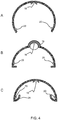
- Figure 4 shows further designs.
- Figure 4A shows that the visible light LEDs may be mounted directly on side wall portions (of a curved reflector design in the example shown) instead of requiring an additional rim.
- Figure 4B shows that the beam shaping arrangement 18 of the UV LED 16 may comprise a shaped part of the support structure, i.e. the housing. This provides a more integrated design with fewer components.
- the housing may have the same material design throughout or they may be different reflection properties at the beam shaping arrangement 18.
- Figure 4C shows that the design of the rim may provide a more complicated beam shaping function for the light output of the visible light LEDs 20.
- Figure 5 shows further designs.
- the light exit window 12 may be an empty opening in the housing.
- Figure 5A shows that there may instead be a solid transparent UV-resistant closure 50. This does not need to be a diffuser and may instead be a transparent (to UV and to visible light) window, for example of glass or quartz or any other transparent substrate which is insensitive to UV.
- Figure 5B shows that the closure 50 may be curved to form a cylindrical or spherical or ellipsoidal outer shape.
- FIG. 5C shows that there may be multiple UV LEDs 16. This applies to all designs.
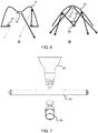
- Figure 6 shows further designs.
- Figure 6A shows that a more complicated housing shape may be used.
- the housing may define a specular reflecting surface which performs a collimation function.
- the specular reflective collimator may be designed such that it collimates the visible (e.g. white) light to form collimated indirect visible (e.g. white) light.
- Figure 6B shows a design with the visible light LED in the direct path of the UV LED 16 but protected by a shield 52 which may be an absorber or a reflector.
- the UV LEDs for example comprise UV-B LEDs and the visible light LEDs for example comprise white light LEDs.
- the housing which forms the reflector arrangement and/or defines the mixing chamber, is preferably made from a plastic material, with a coating if required.
- the plastic may be a silicone material, PMMA, PET, PC, PE.
- the plastic may be provided with reflective particles such as aluminum, silver flakes, Al 2 O 3 , BaSO 4 , TiO 2 , or combinations thereof.
- a reflective layer may be provided, such as aluminum or silver evaporated or deposited onto the plastic surface, or a polymer coating of reflective particles.
- the polymer coating may then comprise aluminum, silver flakes, Al 2 O 3 , BaSO 4 , TiO 2 , or combinations thereof in a matrix material such as polyvinyl butyral (PVB).
- PVB polyvinyl butyral
- the reflectivity of the mixing chamber is for example higher than 80%, more preferably higher than 85%, most preferably above 90%.
- the visible light LEDs are typically white light LEDs.
- the white light for example has a maximum deviation to the black body locus (BBL) of 15 standard deviations of color matching (SDCM), for example less than 10 SDCM or even 5 SDCM.
- SDCM standard deviations of color matching
- the white light may have a color temperature in the range from 2,000 K to 8,000 K, for example 2,500 K to 6,000 K, for example 2,800 K to 5,000 K.
- the white light is light which has a color rendering index of at least 70, more preferably at least 80, and most preferably at least 85.
- the UV LEDs are for example UV-B LEDs. They are designed to provide a dose of UV-B light which is sufficient to provide the advantages of vitamin D production, but not sufficient to cause skin damage.
- the light intensity of the system as a whole is based on each UV-B LED having an output power of 400 ⁇ W to 800 ⁇ W.
- a total number of UV-B LEDs can be for example in the range 1 to 40, giving a total output power in the range 0.4mW to 30mW.
- UV-B LEDs are commercially available, and are mainly used in medical applications, for example for medical photometry. There are also commercially available UV-B lighting products for stimulating plant growth for illuminating terrariums.
- the UV-B wavelength is in the range 280nm to 315nm.
- the invention is not however limited to UV-B output, and the UV LEDs may operate in the UV-A or UV-C bands as well as, or instead of the UV-B band.
- the invention is also not limited to white visible light.
- the invention may be applied to a system delivering any color output or indeed having a controllable color point and/or color temperature.
- FIG. 7 shows lighting devices which may use the system.
- the lighting system may comprise an LED lamp such as a reflector lamp 60 or a tubular LED lamp 62 or it may comprise an LED luminaire 64.
- the combined visible and UV lighting may be used to emulate natural daylight.
- the UV component may be for other purposes such as for skin tanning, insect attraction, skin treatment, disinfection, etc.
Landscapes
- Engineering & Computer Science (AREA)
- Health & Medical Sciences (AREA)
- Biomedical Technology (AREA)
- General Engineering & Computer Science (AREA)
- Life Sciences & Earth Sciences (AREA)
- Animal Behavior & Ethology (AREA)
- Radiology & Medical Imaging (AREA)
- Nuclear Medicine, Radiotherapy & Molecular Imaging (AREA)
- Pathology (AREA)
- General Health & Medical Sciences (AREA)
- Public Health (AREA)
- Veterinary Medicine (AREA)
- Biophysics (AREA)
- Physics & Mathematics (AREA)
- Microelectronics & Electronic Packaging (AREA)
- Optics & Photonics (AREA)
- Non-Portable Lighting Devices Or Systems Thereof (AREA)
- Radiation-Therapy Devices (AREA)
Claims (10)
- Système d'éclairage, comprenant :un boîtier (10) qui comprend une structure de support (14) et une fenêtre de sortie de lumière (12) destinée à émettre de la lumière aux abords du système d'éclairage, le boîtier (10) définissant une chambre de mélange dotée d'une partie supérieure et d'une partie inférieure, la chambre de mélange comprenant une ou plusieurs portions formant paroi latérale (32) et une portion formant paroi supérieure (30) qui forme la partie supérieure, la fenêtre de sortie de lumière (12) étant prévue dans la partie inférieure ;un agencement de DEL UV (16) monté sur la structure de support (14) ;un agencement de DEL de lumière visible (20) monté sur la structure de support (14) ; etun agencement réflecteur (22), dans lequel les DEL de lumière visible (20) font face à l'agencement réflecteur (22), et l'agencement réflecteur (22) sert à réfléchir la sortie de lumière visible provenant des DEL de lumière visible (20) vers la fenêtre de sortie (12),dans lequel les DEL UV (16) sont prévues dans la partie supérieure faisant face à la fenêtre de sortie de lumière (12),caractérisé en ce que les DEL de lumière visible (20) sont montées :(i) sur un rebord (24) autour de la fenêtre de sortie de lumière (12) faisant face à la chambre de mélange et faisant face à la partie supérieure, directement ou de façon oblique,(ii) sur les une ou plusieurs portions formant paroi latérale (32) faisant face à la chambre de mélange, ou(iii) dans la partie supérieure orientée dans la direction de la fenêtre de sortie de lumière (12), l'agencement réflecteur (22) comprenant des portions de réflecteur (34) sur les DEL de lumière visible (20) pour bloquer le trajet de la lumière vers la fenêtre de sortie de lumière (12).
- Système d'éclairage selon la revendication 1, comprenant en outre un agencement de mise en forme de faisceau UV (18) pour mettre en forme la sortie des DEL UV.
- Système d'éclairage selon la revendication 2, dans lequel l'agencement de mise en forme de faisceau UV (18) comprend une partie mise en forme de la structure de support.
- Système d'éclairage selon la revendication 2, dans lequel l'agencement de mise en forme de faisceau UV comprend une enveloppe métallique respective (18) autour de chaque DEL UV ou autour d'ensembles de DEL UV.
- Système d'éclairage selon l'une quelconque des revendications 2 à 4, dans lequel l'agencement de mise en forme de faisceau UV (18) est adapté pour diriger au moins 80 % de la sortie des DEL UV directement vers la fenêtre de sortie (12), par exemple au moins 85 %, par exemple au moins 90 %.
- Système d'éclairage selon l'une quelconque des revendications précédentes, dans lequel au plus 20 % de la sortie de lumière visible provenant des DEL de lumière visible (20) atteint directement la fenêtre de sortie de lumière, par exemple au plus 15 %, par exemple au plus 10 %.
- Système d'éclairage selon l'une quelconque des revendications précédentes, dans lequel la fenêtre de sortie de lumière (12) comprend une ouverture vide formée dans le boîtier.
- Système d'éclairage selon l'une quelconque des revendications 1 à 6, dans lequel la fenêtre de sortie de lumière comporte une enceinte pleine, transparente et résistante aux UV.
- Système d'éclairage selon l'une quelconque des revendications précédentes, dans lequel les DEL UV comprennent des DEL UV-B et les DEL de lumière visible comprennent des DEL de lumière blanche ou des agencements de DEL capables de produire une sortie de lumière blanche.
- Système d'éclairage selon l'une quelconque des revendications précédentes, comprenant une lampe à DEL, telle qu'une lampe réflecteur à DEL ou une lampe à DEL tubulaire, ou un luminaire à DEL.
Applications Claiming Priority (1)
| Application Number | Priority Date | Filing Date | Title |
|---|---|---|---|
| EP16204420 | 2016-12-15 |
Publications (2)
| Publication Number | Publication Date |
|---|---|
| EP3336417A1 EP3336417A1 (fr) | 2018-06-20 |
| EP3336417B1 true EP3336417B1 (fr) | 2020-04-08 |
Family
ID=57629300
Family Applications (1)
| Application Number | Title | Priority Date | Filing Date |
|---|---|---|---|
| EP17205356.3A Active EP3336417B1 (fr) | 2016-12-15 | 2017-12-05 | Système d'éclairage visible et par uv |
Country Status (3)
| Country | Link |
|---|---|
| US (1) | US10364944B2 (fr) |
| EP (1) | EP3336417B1 (fr) |
| CN (1) | CN108224213B (fr) |
Families Citing this family (17)
| Publication number | Priority date | Publication date | Assignee | Title |
|---|---|---|---|---|
| US10670205B2 (en) * | 2018-03-09 | 2020-06-02 | Finelite Inc. | Open channel LED light fixture for indirect lighting |
| US10718476B2 (en) * | 2018-03-09 | 2020-07-21 | Finelite Inc. | LED light fixture for indirect lighting with adaptable baffle structure |
| JP7081352B2 (ja) * | 2018-07-11 | 2022-06-07 | 岩崎電気株式会社 | 照明器具 |
| CH716065A1 (de) * | 2019-04-03 | 2020-10-15 | Jk Holding Gmbh | Vorrichtung zum Einwirken auf zumindest Teile eines Körpers. |
| US11117678B2 (en) * | 2019-05-29 | 2021-09-14 | AVID Labs, LLC | Runway/taxiway lighting system |
| WO2021005029A1 (fr) * | 2019-07-11 | 2021-01-14 | Signify Holding B.V. | Dispositif d'éclairage, luminaire, système d'éclairage et utilisation associée |
| EP4028689A1 (fr) * | 2019-09-12 | 2022-07-20 | Signify Holding B.V. | Luminaire utilisant une chambre de mélange de lumière |
| US11480314B2 (en) * | 2020-02-12 | 2022-10-25 | Mark J. Perlin | Light collimation assembly and light emitting devices |
| DE202020001197U1 (de) | 2020-03-26 | 2020-04-15 | Digitalicht Ag | Beleuchtungsvorrichtung mit integrierter UVCStrahlungsquelle |
| US11628234B2 (en) | 2020-06-01 | 2023-04-18 | Know Labs, Inc. | White light LED light bulbs for ambient lighting and pathogen inactivation |
| US11318220B1 (en) * | 2020-09-18 | 2022-05-03 | Insight Lighting, Inc. | Sanitizing light fixture for displaying information |
| WO2022152553A1 (fr) * | 2021-01-12 | 2022-07-21 | Signify Holding B.V. | Agencement d'éclairage pour illumination et éclairage de désinfection |
| EP4278223B1 (fr) | 2021-01-12 | 2025-09-17 | Signify Holding B.V. | Agencement d'éclairage pour l'éclairement et l'éclairage de désinfection |
| EP4082606B1 (fr) * | 2021-04-30 | 2025-03-26 | Tridonic GmbH & Co. KG | Module à del et système d'éclairage comportant un tel module à del émettant de la lumière ayant un composant uv-b |
| JP2024530272A (ja) * | 2021-08-30 | 2024-08-16 | シグニファイ ホールディング ビー ヴィ | 照明デバイス |
| WO2023139455A1 (fr) * | 2022-01-24 | 2023-07-27 | Havells India Limited | Appareil d'éclairage à rayonnement uv sûr pour la production de vitamine d |
| DE202023106578U1 (de) | 2023-11-10 | 2023-12-05 | Jk-Holding Gmbh | Beleuchtungsvorrichtung mit Dioden zum Emittieren im UV- und VIS-Bereich |
Citations (2)
| Publication number | Priority date | Publication date | Assignee | Title |
|---|---|---|---|---|
| US20100327745A1 (en) * | 2009-06-24 | 2010-12-30 | Mahendra Dassanayake | Opto-thermal solution for multi-utility solid state lighting device using conic section geometries |
| WO2017125322A1 (fr) * | 2016-01-19 | 2017-07-27 | Philips Lighting Holding B.V. | Dispositif d'éclairage |
Family Cites Families (20)
| Publication number | Priority date | Publication date | Assignee | Title |
|---|---|---|---|---|
| US4562517A (en) * | 1983-02-28 | 1985-12-31 | Maximum Technology | Reflector systems for lighting fixtures and method of installation |
| DE4001839A1 (de) * | 1990-01-23 | 1991-07-25 | Adp Automaten Gmbh | Pendelleuchte mit einem eine lichtaustrittsoeffnung aufweisenden leuchtengehaeuse |
| DE29923835U1 (de) * | 1999-04-07 | 2001-04-05 | Zumtobel Staff Gmbh | Beleuchtungsanordnung zur Anbringung an der Decke oder einer Wand eines Raumes |
| US7521667B2 (en) | 2003-06-23 | 2009-04-21 | Advanced Optical Technologies, Llc | Intelligent solid state lighting |
| US6995355B2 (en) * | 2003-06-23 | 2006-02-07 | Advanced Optical Technologies, Llc | Optical integrating chamber lighting using multiple color sources |
| US7025464B2 (en) | 2004-03-30 | 2006-04-11 | Goldeneye, Inc. | Projection display systems utilizing light emitting diodes and light recycling |
| US8109981B2 (en) * | 2005-01-25 | 2012-02-07 | Valam Corporation | Optical therapies and devices |
| JP2010508651A (ja) * | 2006-10-31 | 2010-03-18 | ティーアイアール テクノロジー エルピー | 光励起可能媒体を含む光源 |
| RU2475674C2 (ru) | 2007-05-02 | 2013-02-20 | Конинклейке Филипс Электроникс Н.В. | Твердотельное устройство освещения |
| US8262251B2 (en) | 2009-05-01 | 2012-09-11 | Abl Ip Holding Llc | Light fixture using doped semiconductor nanophosphor in a gas |
| JP5418103B2 (ja) | 2008-09-30 | 2014-02-19 | 東芝ライテック株式会社 | 照明器具 |
| US20120199005A1 (en) | 2009-10-19 | 2012-08-09 | Hoshin Kagaku Sangyosho Co., Ltd. | Lighting and air cleaning device |
| WO2011130648A2 (fr) * | 2010-04-16 | 2011-10-20 | Solais Lighting, Inc. | Structure cellulaire miniature destinée à une optique secondaire de lampe à diode électroluminescente de rattrapage |
| DE102010041096B4 (de) * | 2010-09-21 | 2024-05-08 | Osram Gmbh | Leuchtvorrichtung |
| RU2457393C1 (ru) | 2011-02-17 | 2012-07-27 | Закрытое Акционерное Общество "Научно-Производственная Коммерческая Фирма "Элтан Лтд" | Светодиодный источник белого света с удаленным фотолюминесцентным конвертером |
| KR101319360B1 (ko) * | 2013-03-04 | 2013-10-16 | 유버 주식회사 | 칩온보드형 uv led 패키지 및 그 제조방법 |
| WO2015168768A1 (fr) | 2014-05-05 | 2015-11-12 | Sanuvox Technologies Inc. | Système de décontamination de pièce, procédé et organe commande |
| GB2531319A (en) * | 2014-10-16 | 2016-04-20 | Apollo Uv Ltd | UV lamp unit |
| RU2712928C2 (ru) | 2015-06-16 | 2020-02-03 | Филипс Лайтинг Холдинг Б.В. | Осветительный модуль, излучающий часть уф-света |
| CN105351828A (zh) * | 2015-11-24 | 2016-02-24 | 济南大学 | 一种具有空气净化功能的吊灯 |
-
2017
- 2017-12-05 EP EP17205356.3A patent/EP3336417B1/fr active Active
- 2017-12-05 US US15/832,350 patent/US10364944B2/en active Active
- 2017-12-12 CN CN201711319935.6A patent/CN108224213B/zh not_active Expired - Fee Related
Patent Citations (2)
| Publication number | Priority date | Publication date | Assignee | Title |
|---|---|---|---|---|
| US20100327745A1 (en) * | 2009-06-24 | 2010-12-30 | Mahendra Dassanayake | Opto-thermal solution for multi-utility solid state lighting device using conic section geometries |
| WO2017125322A1 (fr) * | 2016-01-19 | 2017-07-27 | Philips Lighting Holding B.V. | Dispositif d'éclairage |
Also Published As
| Publication number | Publication date |
|---|---|
| CN108224213B (zh) | 2022-04-15 |
| CN108224213A (zh) | 2018-06-29 |
| EP3336417A1 (fr) | 2018-06-20 |
| US20180172219A1 (en) | 2018-06-21 |
| US10364944B2 (en) | 2019-07-30 |
Similar Documents
| Publication | Publication Date | Title |
|---|---|---|
| EP3336417B1 (fr) | Système d'éclairage visible et par uv | |
| JP7213851B2 (ja) | 照明器具 | |
| CN108474544B (zh) | 照明设备 | |
| US10420954B2 (en) | Light exposure apparatus | |
| US11224759B2 (en) | Vitamin D lighting system | |
| EP4278223B1 (fr) | Agencement d'éclairage pour l'éclairement et l'éclairage de désinfection | |
| JP6609426B2 (ja) | 照明装置 | |
| JP2020526899A (ja) | 発光モジュール | |
| US9915414B2 (en) | Luminaire and lighting arrangement | |
| CN118804769A (zh) | 混杂uv-白光光源 | |
| WO2023208642A1 (fr) | Sensibilité à la lumière mélanopique | |
| US20230372559A1 (en) | Ultraviolet downlight for use in disinfecting an environment for human occupation | |
| EP4500078B1 (fr) | Plaque de guide de lumière à gradient d'éclairage | |
| US20260052609A1 (en) | Luminaires for spatial dimming | |
| US20250180797A1 (en) | Lightguide plate with lighting gradient | |
| WO2023232530A1 (fr) | Fenêtre de sortie de lumière à sensibilité au contraste réglable | |
| WO2022152553A1 (fr) | Agencement d'éclairage pour illumination et éclairage de désinfection | |
| WO2021244942A1 (fr) | Système de del présentant un rapport d'efficacité mélanopique élevé |
Legal Events
| Date | Code | Title | Description |
|---|---|---|---|
| PUAI | Public reference made under article 153(3) epc to a published international application that has entered the european phase |
Free format text: ORIGINAL CODE: 0009012 |
|
| STAA | Information on the status of an ep patent application or granted ep patent |
Free format text: STATUS: THE APPLICATION HAS BEEN PUBLISHED |
|
| AK | Designated contracting states |
Kind code of ref document: A1 Designated state(s): AL AT BE BG CH CY CZ DE DK EE ES FI FR GB GR HR HU IE IS IT LI LT LU LV MC MK MT NL NO PL PT RO RS SE SI SK SM TR |
|
| AX | Request for extension of the european patent |
Extension state: BA ME |
|
| RAP1 | Party data changed (applicant data changed or rights of an application transferred) |
Owner name: PHILIPS LIGHTING HOLDING B.V. |
|
| STAA | Information on the status of an ep patent application or granted ep patent |
Free format text: STATUS: REQUEST FOR EXAMINATION WAS MADE |
|
| 17P | Request for examination filed |
Effective date: 20181220 |
|
| RBV | Designated contracting states (corrected) |
Designated state(s): AL AT BE BG CH CY CZ DE DK EE ES FI FR GB GR HR HU IE IS IT LI LT LU LV MC MK MT NL NO PL PT RO RS SE SI SK SM TR |
|
| RAP1 | Party data changed (applicant data changed or rights of an application transferred) |
Owner name: SIGNIFY HOLDING B.V. |
|
| STAA | Information on the status of an ep patent application or granted ep patent |
Free format text: STATUS: EXAMINATION IS IN PROGRESS |
|
| 17Q | First examination report despatched |
Effective date: 20190426 |
|
| GRAP | Despatch of communication of intention to grant a patent |
Free format text: ORIGINAL CODE: EPIDOSNIGR1 |
|
| STAA | Information on the status of an ep patent application or granted ep patent |
Free format text: STATUS: GRANT OF PATENT IS INTENDED |
|
| INTG | Intention to grant announced |
Effective date: 20191108 |
|
| GRAS | Grant fee paid |
Free format text: ORIGINAL CODE: EPIDOSNIGR3 |
|
| GRAA | (expected) grant |
Free format text: ORIGINAL CODE: 0009210 |
|
| STAA | Information on the status of an ep patent application or granted ep patent |
Free format text: STATUS: THE PATENT HAS BEEN GRANTED |
|
| AK | Designated contracting states |
Kind code of ref document: B1 Designated state(s): AL AT BE BG CH CY CZ DE DK EE ES FI FR GB GR HR HU IE IS IT LI LT LU LV MC MK MT NL NO PL PT RO RS SE SI SK SM TR |
|
| REG | Reference to a national code |
Ref country code: AT Ref legal event code: REF Ref document number: 1254863 Country of ref document: AT Kind code of ref document: T Effective date: 20200415 Ref country code: CH Ref legal event code: EP |
|
| REG | Reference to a national code |
Ref country code: DE Ref legal event code: R096 Ref document number: 602017014318 Country of ref document: DE |
|
| REG | Reference to a national code |
Ref country code: IE Ref legal event code: FG4D |
|
| REG | Reference to a national code |
Ref country code: NL Ref legal event code: MP Effective date: 20200408 |
|
| REG | Reference to a national code |
Ref country code: LT Ref legal event code: MG4D |
|
| PG25 | Lapsed in a contracting state [announced via postgrant information from national office to epo] |
Ref country code: IS Free format text: LAPSE BECAUSE OF FAILURE TO SUBMIT A TRANSLATION OF THE DESCRIPTION OR TO PAY THE FEE WITHIN THE PRESCRIBED TIME-LIMIT Effective date: 20200808 Ref country code: PT Free format text: LAPSE BECAUSE OF FAILURE TO SUBMIT A TRANSLATION OF THE DESCRIPTION OR TO PAY THE FEE WITHIN THE PRESCRIBED TIME-LIMIT Effective date: 20200817 Ref country code: SE Free format text: LAPSE BECAUSE OF FAILURE TO SUBMIT A TRANSLATION OF THE DESCRIPTION OR TO PAY THE FEE WITHIN THE PRESCRIBED TIME-LIMIT Effective date: 20200408 Ref country code: NL Free format text: LAPSE BECAUSE OF FAILURE TO SUBMIT A TRANSLATION OF THE DESCRIPTION OR TO PAY THE FEE WITHIN THE PRESCRIBED TIME-LIMIT Effective date: 20200408 Ref country code: NO Free format text: LAPSE BECAUSE OF FAILURE TO SUBMIT A TRANSLATION OF THE DESCRIPTION OR TO PAY THE FEE WITHIN THE PRESCRIBED TIME-LIMIT Effective date: 20200708 Ref country code: FI Free format text: LAPSE BECAUSE OF FAILURE TO SUBMIT A TRANSLATION OF THE DESCRIPTION OR TO PAY THE FEE WITHIN THE PRESCRIBED TIME-LIMIT Effective date: 20200408 Ref country code: LT Free format text: LAPSE BECAUSE OF FAILURE TO SUBMIT A TRANSLATION OF THE DESCRIPTION OR TO PAY THE FEE WITHIN THE PRESCRIBED TIME-LIMIT Effective date: 20200408 Ref country code: GR Free format text: LAPSE BECAUSE OF FAILURE TO SUBMIT A TRANSLATION OF THE DESCRIPTION OR TO PAY THE FEE WITHIN THE PRESCRIBED TIME-LIMIT Effective date: 20200709 |
|
| REG | Reference to a national code |
Ref country code: AT Ref legal event code: MK05 Ref document number: 1254863 Country of ref document: AT Kind code of ref document: T Effective date: 20200408 |
|
| PG25 | Lapsed in a contracting state [announced via postgrant information from national office to epo] |
Ref country code: BG Free format text: LAPSE BECAUSE OF FAILURE TO SUBMIT A TRANSLATION OF THE DESCRIPTION OR TO PAY THE FEE WITHIN THE PRESCRIBED TIME-LIMIT Effective date: 20200708 Ref country code: LV Free format text: LAPSE BECAUSE OF FAILURE TO SUBMIT A TRANSLATION OF THE DESCRIPTION OR TO PAY THE FEE WITHIN THE PRESCRIBED TIME-LIMIT Effective date: 20200408 Ref country code: RS Free format text: LAPSE BECAUSE OF FAILURE TO SUBMIT A TRANSLATION OF THE DESCRIPTION OR TO PAY THE FEE WITHIN THE PRESCRIBED TIME-LIMIT Effective date: 20200408 Ref country code: HR Free format text: LAPSE BECAUSE OF FAILURE TO SUBMIT A TRANSLATION OF THE DESCRIPTION OR TO PAY THE FEE WITHIN THE PRESCRIBED TIME-LIMIT Effective date: 20200408 |
|
| PG25 | Lapsed in a contracting state [announced via postgrant information from national office to epo] |
Ref country code: AL Free format text: LAPSE BECAUSE OF FAILURE TO SUBMIT A TRANSLATION OF THE DESCRIPTION OR TO PAY THE FEE WITHIN THE PRESCRIBED TIME-LIMIT Effective date: 20200408 |
|
| REG | Reference to a national code |
Ref country code: DE Ref legal event code: R097 Ref document number: 602017014318 Country of ref document: DE |
|
| PG25 | Lapsed in a contracting state [announced via postgrant information from national office to epo] |
Ref country code: EE Free format text: LAPSE BECAUSE OF FAILURE TO SUBMIT A TRANSLATION OF THE DESCRIPTION OR TO PAY THE FEE WITHIN THE PRESCRIBED TIME-LIMIT Effective date: 20200408 Ref country code: AT Free format text: LAPSE BECAUSE OF FAILURE TO SUBMIT A TRANSLATION OF THE DESCRIPTION OR TO PAY THE FEE WITHIN THE PRESCRIBED TIME-LIMIT Effective date: 20200408 Ref country code: DK Free format text: LAPSE BECAUSE OF FAILURE TO SUBMIT A TRANSLATION OF THE DESCRIPTION OR TO PAY THE FEE WITHIN THE PRESCRIBED TIME-LIMIT Effective date: 20200408 Ref country code: RO Free format text: LAPSE BECAUSE OF FAILURE TO SUBMIT A TRANSLATION OF THE DESCRIPTION OR TO PAY THE FEE WITHIN THE PRESCRIBED TIME-LIMIT Effective date: 20200408 Ref country code: IT Free format text: LAPSE BECAUSE OF FAILURE TO SUBMIT A TRANSLATION OF THE DESCRIPTION OR TO PAY THE FEE WITHIN THE PRESCRIBED TIME-LIMIT Effective date: 20200408 Ref country code: SM Free format text: LAPSE BECAUSE OF FAILURE TO SUBMIT A TRANSLATION OF THE DESCRIPTION OR TO PAY THE FEE WITHIN THE PRESCRIBED TIME-LIMIT Effective date: 20200408 Ref country code: CZ Free format text: LAPSE BECAUSE OF FAILURE TO SUBMIT A TRANSLATION OF THE DESCRIPTION OR TO PAY THE FEE WITHIN THE PRESCRIBED TIME-LIMIT Effective date: 20200408 Ref country code: ES Free format text: LAPSE BECAUSE OF FAILURE TO SUBMIT A TRANSLATION OF THE DESCRIPTION OR TO PAY THE FEE WITHIN THE PRESCRIBED TIME-LIMIT Effective date: 20200408 |
|
| PLBE | No opposition filed within time limit |
Free format text: ORIGINAL CODE: 0009261 |
|
| STAA | Information on the status of an ep patent application or granted ep patent |
Free format text: STATUS: NO OPPOSITION FILED WITHIN TIME LIMIT |
|
| PG25 | Lapsed in a contracting state [announced via postgrant information from national office to epo] |
Ref country code: SK Free format text: LAPSE BECAUSE OF FAILURE TO SUBMIT A TRANSLATION OF THE DESCRIPTION OR TO PAY THE FEE WITHIN THE PRESCRIBED TIME-LIMIT Effective date: 20200408 Ref country code: PL Free format text: LAPSE BECAUSE OF FAILURE TO SUBMIT A TRANSLATION OF THE DESCRIPTION OR TO PAY THE FEE WITHIN THE PRESCRIBED TIME-LIMIT Effective date: 20200408 |
|
| 26N | No opposition filed |
Effective date: 20210112 |
|
| PG25 | Lapsed in a contracting state [announced via postgrant information from national office to epo] |
Ref country code: SI Free format text: LAPSE BECAUSE OF FAILURE TO SUBMIT A TRANSLATION OF THE DESCRIPTION OR TO PAY THE FEE WITHIN THE PRESCRIBED TIME-LIMIT Effective date: 20200408 |
|
| REG | Reference to a national code |
Ref country code: CH Ref legal event code: PL |
|
| PG25 | Lapsed in a contracting state [announced via postgrant information from national office to epo] |
Ref country code: MC Free format text: LAPSE BECAUSE OF FAILURE TO SUBMIT A TRANSLATION OF THE DESCRIPTION OR TO PAY THE FEE WITHIN THE PRESCRIBED TIME-LIMIT Effective date: 20200408 |
|
| REG | Reference to a national code |
Ref country code: BE Ref legal event code: MM Effective date: 20201231 |
|
| PG25 | Lapsed in a contracting state [announced via postgrant information from national office to epo] |
Ref country code: LU Free format text: LAPSE BECAUSE OF NON-PAYMENT OF DUE FEES Effective date: 20201205 Ref country code: IE Free format text: LAPSE BECAUSE OF NON-PAYMENT OF DUE FEES Effective date: 20201205 |
|
| PG25 | Lapsed in a contracting state [announced via postgrant information from national office to epo] |
Ref country code: CH Free format text: LAPSE BECAUSE OF NON-PAYMENT OF DUE FEES Effective date: 20201231 Ref country code: LI Free format text: LAPSE BECAUSE OF NON-PAYMENT OF DUE FEES Effective date: 20201231 |
|
| PG25 | Lapsed in a contracting state [announced via postgrant information from national office to epo] |
Ref country code: TR Free format text: LAPSE BECAUSE OF FAILURE TO SUBMIT A TRANSLATION OF THE DESCRIPTION OR TO PAY THE FEE WITHIN THE PRESCRIBED TIME-LIMIT Effective date: 20200408 Ref country code: MT Free format text: LAPSE BECAUSE OF FAILURE TO SUBMIT A TRANSLATION OF THE DESCRIPTION OR TO PAY THE FEE WITHIN THE PRESCRIBED TIME-LIMIT Effective date: 20200408 Ref country code: CY Free format text: LAPSE BECAUSE OF FAILURE TO SUBMIT A TRANSLATION OF THE DESCRIPTION OR TO PAY THE FEE WITHIN THE PRESCRIBED TIME-LIMIT Effective date: 20200408 |
|
| PG25 | Lapsed in a contracting state [announced via postgrant information from national office to epo] |
Ref country code: MK Free format text: LAPSE BECAUSE OF FAILURE TO SUBMIT A TRANSLATION OF THE DESCRIPTION OR TO PAY THE FEE WITHIN THE PRESCRIBED TIME-LIMIT Effective date: 20200408 |
|
| PG25 | Lapsed in a contracting state [announced via postgrant information from national office to epo] |
Ref country code: BE Free format text: LAPSE BECAUSE OF NON-PAYMENT OF DUE FEES Effective date: 20201231 |
|
| PGFP | Annual fee paid to national office [announced via postgrant information from national office to epo] |
Ref country code: GB Payment date: 20221220 Year of fee payment: 6 Ref country code: FR Payment date: 20221222 Year of fee payment: 6 |
|
| PGFP | Annual fee paid to national office [announced via postgrant information from national office to epo] |
Ref country code: DE Payment date: 20230224 Year of fee payment: 6 |
|
| P01 | Opt-out of the competence of the unified patent court (upc) registered |
Effective date: 20230425 |
|
| REG | Reference to a national code |
Ref country code: DE Ref legal event code: R119 Ref document number: 602017014318 Country of ref document: DE |
|
| GBPC | Gb: european patent ceased through non-payment of renewal fee |
Effective date: 20231205 |
|
| PG25 | Lapsed in a contracting state [announced via postgrant information from national office to epo] |
Ref country code: DE Free format text: LAPSE BECAUSE OF NON-PAYMENT OF DUE FEES Effective date: 20240702 |
|
| PG25 | Lapsed in a contracting state [announced via postgrant information from national office to epo] |
Ref country code: GB Free format text: LAPSE BECAUSE OF NON-PAYMENT OF DUE FEES Effective date: 20231205 |
|
| PG25 | Lapsed in a contracting state [announced via postgrant information from national office to epo] |
Ref country code: FR Free format text: LAPSE BECAUSE OF NON-PAYMENT OF DUE FEES Effective date: 20231231 |
|
| PG25 | Lapsed in a contracting state [announced via postgrant information from national office to epo] |
Ref country code: GB Free format text: LAPSE BECAUSE OF NON-PAYMENT OF DUE FEES Effective date: 20231205 Ref country code: FR Free format text: LAPSE BECAUSE OF NON-PAYMENT OF DUE FEES Effective date: 20231231 Ref country code: DE Free format text: LAPSE BECAUSE OF NON-PAYMENT OF DUE FEES Effective date: 20240702 |