EP3336603B1 - Anzeigebildschirm - Google Patents
Anzeigebildschirm Download PDFInfo
- Publication number
- EP3336603B1 EP3336603B1 EP15900856.4A EP15900856A EP3336603B1 EP 3336603 B1 EP3336603 B1 EP 3336603B1 EP 15900856 A EP15900856 A EP 15900856A EP 3336603 B1 EP3336603 B1 EP 3336603B1
- Authority
- EP
- European Patent Office
- Prior art keywords
- display screen
- view
- cylindrical portion
- cut
- present application
- Prior art date
- Legal status (The legal status is an assumption and is not a legal conclusion. Google has not performed a legal analysis and makes no representation as to the accuracy of the status listed.)
- Active
Links
Images








Classifications
-
- G—PHYSICS
- G03—PHOTOGRAPHY; CINEMATOGRAPHY; ANALOGOUS TECHNIQUES USING WAVES OTHER THAN OPTICAL WAVES; ELECTROGRAPHY; HOLOGRAPHY
- G03B—APPARATUS OR ARRANGEMENTS FOR TAKING PHOTOGRAPHS OR FOR PROJECTING OR VIEWING THEM; APPARATUS OR ARRANGEMENTS EMPLOYING ANALOGOUS TECHNIQUES USING WAVES OTHER THAN OPTICAL WAVES; ACCESSORIES THEREFOR
- G03B21/00—Projectors or projection-type viewers; Accessories therefor
- G03B21/54—Accessories
- G03B21/56—Projection screens
-
- G—PHYSICS
- G03—PHOTOGRAPHY; CINEMATOGRAPHY; ANALOGOUS TECHNIQUES USING WAVES OTHER THAN OPTICAL WAVES; ELECTROGRAPHY; HOLOGRAPHY
- G03B—APPARATUS OR ARRANGEMENTS FOR TAKING PHOTOGRAPHS OR FOR PROJECTING OR VIEWING THEM; APPARATUS OR ARRANGEMENTS EMPLOYING ANALOGOUS TECHNIQUES USING WAVES OTHER THAN OPTICAL WAVES; ACCESSORIES THEREFOR
- G03B21/00—Projectors or projection-type viewers; Accessories therefor
- G03B21/54—Accessories
- G03B21/56—Projection screens
- G03B21/60—Projection screens characterised by the nature of the surface
- G03B21/606—Projection screens characterised by the nature of the surface for relief projection
-
- G—PHYSICS
- G03—PHOTOGRAPHY; CINEMATOGRAPHY; ANALOGOUS TECHNIQUES USING WAVES OTHER THAN OPTICAL WAVES; ELECTROGRAPHY; HOLOGRAPHY
- G03B—APPARATUS OR ARRANGEMENTS FOR TAKING PHOTOGRAPHS OR FOR PROJECTING OR VIEWING THEM; APPARATUS OR ARRANGEMENTS EMPLOYING ANALOGOUS TECHNIQUES USING WAVES OTHER THAN OPTICAL WAVES; ACCESSORIES THEREFOR
- G03B37/00—Panoramic or wide-screen photography; Photographing extended surfaces, e.g. for surveying; Photographing internal surfaces, e.g. of pipe
Definitions
- the present application relates to the technical field of display, and in particular, relates to a display screen.
- the display screens in the prior art may be categorized into planar screens, circular screens, and dome screens.
- High Presence Display (ISBN: 7030110218 KuSenzoku from Japan) has disclosed that high presence is formed by the following factors: high definition, full color, three-dimensional, and no boundary.
- No boundary refers to that the ordinary audiences, in the normal visual field range, fail to see the boundary between the image displayed on the display screen and the realistic world, that is, fail to see the boundary on the display screen, such that the audiences have a strong sense of immersion.
- the planar screen, the circular screen and the dome screen achieve the effects of high definition, full color and three-dimensional.
- the planar screen and the circular screen may not be made infinitely large, and may not enclose the audiences. Therefore, the planar screen and the circular screen may not be made to have no boundary.
- the dome screen is capable of better enclosing the audiences, and the audiences may not see the boundary on the display screen in the normal visual range. Therefore, only the dome screen may be made to have no boundary and achieve the objective of creating a strong sense of immersion for the audiences.
- US8054547B2 (authorized on November 8, 2011 ) has disclosed a seamless, non-shaded rear projection dome display system, wherein the system includes a 360-degree display screen spliced by a plurality of translucent screens, and the spliced display screen is in a dome shape, that is, a partially-dome screen shape.
- This display screen is hard to be built, and needs a high economy, time and labor cost.
- US patent US8992336B2 (authorized on March 31, 2015 ) has disclosed a cinematic theater structure, wherein the cinematic theater structure includes a dome-shaped screen, that is, a partially dome screen, the screen may include a dome head or includes no dome head, and the dome-shaped screen surrounds the seats of the audiences.
- the dome screen mentioned in the prior art includes the dome screen in the above patent documents.
- the dome screen has the advantages of creating a strong sense of immersion for the audiences, in practice, since the seats of the audiences are arranged in a plurality of rows, the audiences seated on two sides of the theater far away from the middle seats would see a high inclination of the dome screen in a horizontal direction, which is not a normal view angle for the human eyes. As a result, the audiences may feel uncomfortable. To make the audiences seated on the sides watch comfortably, the dome screen needs to have a larger radius. Consequently, the manufacturing cost of the dome screen is high.
- the present application provides a display screen, which increases the sense of immersion of the audience and improves comfort of the audience, and occupies a smaller installation space.
- Embodiments of the present application provide a display screen according to appended independent claim 1.
- the cross section of the cylindrical portion comprises a circle, an ellipse, an unsymmetrical circle, or a quadrangle with rounded corners.
- the quadrangle when the cross section of the cylindrical portion is a quadrangle with rounded corners, the quadrangle is a rectangular.
- the housing structure further comprises one or two end portions
- the cylindrical portion is integratable with or detachable from the end portion.
- the cross section of the cylindrical portion is a circle, and the end portion is a semispherical structure.
- the display screen includes a self-luminous display screen or a projection display screen.
- the display screen is configured to display a planar image or a three-dimensional image.
- a conventional display screen includes a planar screen, a circular screen and a dome screen.
- the planar screen refers to a screen which is a plane and typically in a rectangular shape.
- the circular screen refers to a circular-shape screen which has a specific height.
- the dome screen refers to a screen which is in a standard ball-shape.
- the length and width of the planar screen, and the height of the circular screen may not be made infinitely large. Therefore, the audience may see the boundary between an image displayed on the display screen and a realistic world.
- the dome screen may fully enclose or partially enclose the audiences, and thus the audiences may not see the boundary between the image displayed on the dome screen and the realistic world in the visual field, and the audiences feel like being seated in the world presented by the image played on the dome screen. In this way, the audiences achieve a very strong sense of immersion.
- the inventors have found that under common circumstances, the seats of the audiences are arranged in a plurality of rows, the central seats are generally close to or located at the center portion of the dome screen, the audiences seated in the central seats may horizontally watch a symmetrical dome screen and thus have high comfort, whereas the audiences seated far away from the central seats horizontally watch a greatly-inclined screen and thus have low comfort. If the comfort of the audiences seated far away from the central seats is to be ensured, the diameter of the dome screen needs to be sufficiently great, and thus the project cost is typically high.
- an embodiment of the present application provides a display screen.
- the display screen is in a fully-enclosed or partially-enclosed housing structure.
- An interior of the housing structure is configured to provide continuous images with a view angle of 180 degrees to 360 degrees in a horizontal direction.
- the housing structure includes a cylindrical portion, wherein a side wall of the cylindrical portion is arranged in a smooth arc line or straight line on an axial cross section, and if the side wall of the cylindrical portion is arranged in the arc line, the radius of a circle corresponding to the arc line is greater than a maximum vertical distance from the arc line to an axial line.
- FIG. 1 is a schematic view of an axial cross section of the cylindrical portion of the display screen according to this embodiment.
- the dotted line xx' represents an axial line of the cylindrical portion, and the side wall of the cylindrical portion is arranged in the smooth arc line on the axial cross section, and the circle corresponding to the arc line has a center point O and a radius R.
- the maximum distance from the arc line to the axial line xx' is h.
- the dotted-line circle formed with n being the center point and H being the radius thereof represents the axial cross section of the dome screen.
- a dome screen with the radius R (represented by the solid-line circle) needs to be constructed.
- the area of the circle with the radius R is greater than the area of the cross section of the cylindrical portion. Therefore, if the dome screen with the radius R is constructed, the volume of the cylindrical portion may be less than the volume of the dome screen. In this case, the display screen according to this embodiment further effectively saves the manufacturing cost.
- FIG. 1 depicts that the side wall of the cylindrical portion is arranged in the arc line on the axial cross section according to this embodiment.
- the side wall of the cylindrical portion may also be arranged in a straight line on the axial cross section.
- the distances from all the points on the side wall of the cylindrical portion to the axial line of the cylindrical portion are the same. That is, for the audiences seated in the same row, they have the same comfort when they watch the screen towards the forward direction, and they achieve the maximum comfort in the horizontal direction. However, the dome screen fails to achieve such comfort.
- the display screen according to this embodiment has an even smaller volume, which saves the manufacturing cost.
- the display screen is in a housing structure, wherein the housing structure may be a fully-enclosed structure or a partially-enclosed structure.
- the housing structure includes two end portions configured to enclose the cylindrical portion, wherein the two end portions are connected to the cylindrical portion in a smooth transition manner.
- the end portions may also be integratable with or detachable from the cylindrical portion.
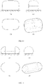
- FIG. 2(a) is a front view of the display screen (the slanted line represents the ground, and the same applies analogously hereinafter),
- FIG. 2(b) is a top view of the display screen
- FIG. 2(c) is a left (or right) view of the display screen
- FIG. 2(d) is a three dimensional view of the display screen.
- the cross section of the cylindrical portion of the display screen is a circle
- the two end portions are in a semispherical shape
- the entire housing structure is similar to a capsule shape.
- the present application sets no limitation to the specific value of the radius of the circle, and a person skilled in the art may customize the radius according to actual needs.
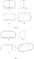
- FIG. 3(a) is a front view of the display screen
- FIG. 3(b) is a top view of the display screen
- FIG. 3(c) is a left (or right) view of the display screen
- FIG. 3(d) is a three dimensional view of the display screen.
- the cross section of the cylindrical portion of the display screen is an elliptical shape.
- the present application either sets no limitation to the specific value of the long axis and the short axis or sets no limitation to the ratio of the long axis to the short axis, and a person skilled in the art may customize the two axes and the ratio of the long axis to the short axis.
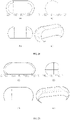
- FIG. 4(a) is a front view of the display screen
- FIG. 4(b) is a top view of the display screen
- FIG. 4(c) is a left (or right) view of the display screen
- FIG. 4(d) is a three dimensional view of the display screen.
- the cross section of the cylindrical portion of the display screen is a square with rounded corners.
- the cross section of the cylindrical portion may also be a rectangular with rounded corners or other quadrangles. Configuration of the rounded corners is to ensure a smooth transition to the two end portions.
- the present application either sets no limitation to the specific values of the lengths of the sides of the quadrangle or sets no limitation to the radius r of the rounded corners, and a person skilled in the art may customize the specific values of the side lengths and the radius of the rounded corners according to actual needs.
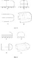
- FIG. 5(a) is a front view of the display screen
- FIG. 5(b) is a top view of the display screen
- FIG. 5(c) is a left (or right) view of the display screen
- FIG. 5(d) is a three dimensional view of the display screen.
- the cross section of the cylindrical portion of the display screen is a top-bottom unsymmetrical circle.
- the cross section of the cylindrical portion may be a left-right unsymmetrical circle.
- the present application sets no limitation to the specific parameters of the unsymmetrical circle, and a person skilled in the art may customize the specific parameters of the unsymmetrical circle according to actual needs.
- FIG. 2 to FIG. 5 illustrate the embodiments in which the side wall of the cylindrical portion is arranged in the straight line in the axial cross section. It may be understood that the above embodiments construe no limitation to the present application, and any embodiment in which the side wall of the cylindrical portion is arranged in the straight line on the axial cross section falls within the protection scope of the present application. In addition, the embodiments as illustrated in FIG. 2 to FIG. 5 are the same in that the side wall of the cylindrical portion is arranged in the straight line on the axial cross section, but are different in that the cylindrical portions have different cross sections, some of which have a great radian whereas some of which have a small radian.
- the display screen whose cross section is a quadrangle with rounded corners has an optimal visual effect.
- FIG. 6(a) is a front view of the display screen
- FIG. 6(b) is a top view of the display screen
- FIG. 6(c) is a left (or right) view of the display screen
- FIG. 6(d) is a three dimensional view of the display screen.
- the entire housing structure of the display screen is an ellipsoid, and the ellipsoid has a circular cross section.
- the present application sets no limitation to the specific parameters of the ellipsoid in FIG. 6 , and a person skilled in the art may customize the specific parameters of the ellipsoid according to actual needs.
- FIG. 7(a) is a front view of the display screen
- FIG. 7(b) is a top view of the display screen
- FIG. 7(c) is a left (or right) view of the display screen
- FIG. 7(d) is a three dimensional view of the display screen.
- the entire housing structure of the display screen in FIG. 7 is also an ellipsoid.
- the ellipsoid has an elliptical cross section.
- the present application sets no limitation to the specific parameters of the ellipsoid in FIG. 7 , and a person skilled in the art may customize the specific parameters of the ellipsoid according to actual needs.
- the side wall of the cylindrical portion is arranged in the arc line shape on the axial cross section; and when the side wall of the cylindrical portion is arranged in the arc line shape on the axial cross section, the cross section of the cylindrical portion may be an unsymmetrical circle, a quadrangle with rounded corners or the like. It should be noted that the arrangement of the side wall of the cylindrical portion in the arc line or straight line on the axial cross section does not necessarily signify that all the side walls of the cylindrical portion are arranged in one line shape on the axial cross section.
- a portion of the side walls may be arranged in the straight line shape and a portion of the side walls may be arranged in the arc line shape.
- the side walls of the display screen facing towards the audiences are arranged in the straight line shape, whereas the side walls of the display screen on the top of the audiences are arranged in the arc line shape.
- the above embodiments describe the display screen having a fully-enclosed housing structure.
- the fully-enclosed display screen is advantageous in that the audiences are capable of watching displayed images over 360 degrees, and the audiences have a good non-boundary experience.
- the cost is high.
- the display screen may employ a partially-enclosed housing structure.
- the display screen having a partially-enclosed housing structure are described.
- the bottom portion of the display screen may be "cut".
- FIG. 8 illustrates a display screen in FIG. 2 with a bottom portion being "cut".
- FIG. 8(a) is a front view of the display screen
- FIG. 8(b) is a top view of the display screen
- FIG. 8(c) is a left (or right) view of the display screen
- FIG. 8(d) is a three-dimensional view of the display screen.
- FIG. 9 illustrates a display screen in FIG. 3 with a bottom portion being "cut".
- FIG. 9(a) is a front view of the display screen
- FIG. 9(b) is a top view of the display screen
- FIG. 9(c) is a left (or right) view of the display screen
- FIG. 9(d) is a three-dimensional view of the display screen.
- FIG. 10 illustrates a display screen in FIG. 4 with a bottom portion being "cut".
- FIG. 10(a) is a front view of the display screen
- FIG. 10(b) is a top view of the display screen
- FIG. 10(c) is a left (or right) view of the display screen
- FIG. 10(d) is a three-dimensional view of the display screen.
- FIG. 11 illustrates a display screen in FIG. 5 with a bottom portion being "cut".
- FIG. 11(a) is a front view of the display screen
- FIG. 11(b) is a top view of the display screen
- FIG. 11(c) is a left (or right) view of the display screen
- FIG. 11(d) is a three-dimensional view of the display screen.
- FIG. 12 illustrates a display screen in FIG. 6 with a bottom portion being "cut".
- FIG. 12(a) is a front view of the display screen
- FIG. 12(b) is a top view of the display screen
- FIG. 12(c) is a left (or right) view of the display screen
- FIG. 12(d) is a three-dimensional view of the display screen.
- FIG. 13 illustrates a display screen in FIG. 7 with a bottom portion being "cut".
- FIG. 13(a) is a front view of the display screen
- FIG. 13(b) is a top view of the display screen
- FIG. 13(c) is a left (or right) view of the display screen
- FIG. 13(d) is a three-dimensional view of the display screen.
- the present application sets no limitation to the specifically “cut” portion of the display screen, that is, the degree of the "opening" of the housing structure.
- the portion to be cut may be determined according to the size and position of the seat platform of the audiences, the size of the display screen and the like, as long as the audiences are capable of normally watching the display images in the vertical direction and achieving the sense of no boundary.
- the lower boundary of the vertical vision field of the eyes of the audiences is 70 degrees below the eye level.
- the rear portion of the display screen may be "cut".
- FIG. 14 illustrates a display screen in FIG. 2 with a rear portion being "cut".
- FIG. 14(a) is a front view of the display screen
- FIG. 14(b) is a top view of the display screen
- FIG. 14(c) is a left (or right) view of the display screen
- FIG. 14(d) is a three-dimensional view of the display screen.
- FIG. 15 illustrates a display screen in FIG. 3 with a rear portion being "cut".
- FIG. 15(a) is a front view of the display screen
- FIG. 15(b) is a top view of the display screen
- FIG. 15(c) is a left (or right) view of the display screen
- FIG. 15(d) is a three-dimensional view of the display screen.
- FIG. 16 illustrates a display screen in FIG. 4 with a rear portion being "cut".
- FIG. 16(a) is a front view of the display screen
- FIG. 16(b) is a top view of the display screen
- FIG. 16(c) is a left (or right) view of the display screen
- FIG. 16(d) is a three-dimensional view of the display screen.
- FIG. 17 illustrates a display screen in FIG. 5 with a rear portion being "cut".
- FIG. 17(a) is a front view of the display screen
- FIG. 17(b) is a top view of the display screen
- FIG. 17(c) is a left (or right) view of the display screen
- FIG. 17(d) is a three-dimensional view of the display screen.
- FIG. 18 illustrates a display screen in FIG. 6 with a rear portion being "cut".
- FIG. 18(a) is a front view of the display screen
- FIG. 18(b) is a top view of the display screen
- FIG. 18(c) is a left (or right) view of the display screen
- FIG. 18(d) is a three-dimensional view of the display screen.
- FIG. 19 illustrates a display screen in FIG. 7 with a rear portion being "cut".
- FIG. 19(a) is a front view of the display screen
- FIG. 19(b) is a top view of the display screen
- FIG. 19(c) is a left (or right) view of the display screen
- FIG. 19(d) is a three-dimensional view of the display screen.
- the present application sets no limitation to the specifically "cut" rear portion of the display screen, that is, the degree of the "opening" of the housing structure.
- the portion to be cut may be determined according to the size and positions of the seats of the audiences, the size of the display screen and the like, as long as the audiences are capable of normally watching the display images and achieving the sense of no boundary.
- the upper boundary of the vertical vision field of the eyes of the audiences is 50 degrees above the eye level.
- the bottom portion and the rear portion of the display screen may be both "cut".
- FIG. 20 illustrates a display screen in FIG. 2 with a bottom portion and a rear portion being both "cut".
- FIG. 20(a) is a front view of the display screen
- FIG. 20(b) is a top view of the display screen
- FIG. 20(c) is a left (or right) view of the display screen
- FIG. 20(d) is a three-dimensional view of the display screen.
- FIG. 21 illustrates a display screen in FIG. 3 with a bottom portion and a rear portion being both "cut".
- FIG. 21(a) is a front view of the display screen
- FIG. 21(b) is a top view of the display screen
- FIG. 21(c) is a left (or right) view of the display screen
- FIG. 21(d) is a three-dimensional view of the display screen.
- FIG. 22 illustrates a display screen in FIG. 4 with a bottom portion and a rear portion being both "cut".
- FIG. 22(a) is a front view of the display screen
- FIG. 22(b) is a top view of the display screen
- FIG. 22(c) is a left (or right) view of the display screen
- FIG. 22(d) is a three-dimensional view of the display screen.
- FIG. 23 illustrates a display screen in FIG. 5 with a bottom portion and a rear portion being both "cut".
- FIG. 23(a) is a front view of the display screen
- FIG. 23(b) is a top view of the display screen
- FIG. 23(c) is a left (or right) view of the display screen
- FIG. 23(d) is a three-dimensional view of the display screen.
- FIG. 24 illustrates a display screen in FIG. 6 with a bottom portion and a rear portion being both "cut".
- FIG. 24(a) is a front view of the display screen
- FIG. 24(b) is a top view of the display screen
- FIG. 24(c) is a left (or right) view of the display screen
- FIG. 24(d) is a three-dimensional view of the display screen.
- FIG. 25 illustrates a display screen in FIG. 7 with a bottom portion and a rear portion being both "cut".
- FIG. 25(a) is a front view of the display screen
- FIG. 25(b) is a top view of the display screen
- FIG. 25(c) is a left (or right) view of the display screen
- FIG. 25(d) is a three-dimensional view of the display screen.
- the present application sets no limitation to the specifically "cut" bottom portion and rear portion of the display screen.
- the portion to be cut may be determined according to the size and position of the seat platform of the audiences, the size of the display screen and the like, as long as the audiences are capable of normally watching the display images and achieving the sense of no boundary.
- the upper boundary of the vertical vision field of the eyes of the audiences is 50 degrees above the eye level, and the lower boundary is 70 degrees below the eye level.
- FIG. 1 to FIG. 25 all employ a symmetrical structure in the horizontal direction.
- an unsymmetrical structure may also be employed.
- the housing structure has only one end portion.
- FIG. 26 illustrates a display screen in FIG. 2 with an end portion being "cut".
- FIG. 26(a) is a front view of the display screen
- FIG. 26(b) is a top view of the display screen
- FIG. 26(c) is a left (or right) view of the display screen
- FIG. 26(d) is a three-dimensional view of the display screen.
- FIG. 27 illustrates a display screen in FIG. 3 with an end portion being "cut".
- FIG. 27(a) is a front view of the display screen
- FIG. 27(b) is a top view of the display screen
- FIG. 27(c) is a left (or right) view of the display screen
- FIG. 27(d) is a three-dimensional view of the display screen.
- FIG. 28 illustrates a display screen in FIG. 4 with an end portion being "cut".
- FIG. 28(a) is a front view of the display screen
- FIG. 28(b) is a top view of the display screen
- FIG. 28(c) is a left (or right) view of the display screen
- FIG. 28(d) is a three-dimensional view of the display screen.
- FIG. 29 illustrates a display screen in FIG. 5 with an end portion being "cut".
- FIG. 29(a) is a front view of the display screen
- FIG. 29(b) is a top view of the display screen
- FIG. 29(c) is a left (or right) view of the display screen
- FIG. 29(d) is a three-dimensional view of the display screen.
- FIG. 30 illustrates a display screen in FIG. 6 with an end portion being "cut".
- FIG. 30(a) is a front view of the display screen
- FIG. 30(b) is a top view of the display screen
- FIG. 30(c) is a left (or right) view of the display screen
- FIG. 30(d) is a three-dimensional view of the display screen.
- FIG. 31 illustrates a display screen in FIG. 7 with an end portion being "cut".
- FIG. 31(a) is a front view of the display screen
- FIG. 31(b) is a top view of the display screen
- FIG. 31(c) is a left (or right) view of the display screen
- FIG. 31(d) is a three-dimensional view of the display screen.
- the housing structure has only one end portion.
- the bottom portion of the housing structure may be "cut".
- FIG. 32 illustrates a display screen in FIG. 2 with an end portion and a bottom portion being both "cut".
- FIG. 32(a) is a front view of the display screen
- FIG. 32(b) is a top view of the display screen
- FIG. 32(c) is a left (or right) view of the display screen
- FIG. 32(d) is a three-dimensional view of the display screen.
- FIG. 33 illustrates a display screen in FIG. 3 with an end portion and a bottom portion being both "cut".
- FIG. 33(a) is a front view of the display screen
- FIG. 33(b) is a top view of the display screen
- FIG. 33(c) is a left (or right) view of the display screen
- FIG. 33(d) is a three-dimensional view of the display screen.
- FIG. 34 illustrates a display screen in FIG. 4 with an end portion and a bottom portion being both "cut".
- FIG. 34(a) is a front view of the display screen
- FIG. 34(b) is a top view of the display screen
- FIG. 34(c) is a left (or right) view of the display screen
- FIG. 34(d) is a three-dimensional view of the display screen.
- FIG. 35 illustrates a display screen in FIG. 5 with an end portion and a bottom portion being both "cut".
- FIG. 35(a) is a front view of the display screen
- FIG. 35(b) is a top view of the display screen
- FIG. 35(c) is a left (or right) view of the display screen
- FIG. 35(d) is a three-dimensional view of the display screen.
- FIG. 36 illustrates a display screen in FIG. 6 with an end portion and a bottom portion being both "cut".
- FIG. 36(a) is a front view of the display screen
- FIG. 36(b) is a top view of the display screen
- FIG. 36(c) is a left (or right) view of the display screen
- FIG. 36(d) is a three-dimensional view of the display screen.
- FIG. 37 illustrates a display screen in FIG. 7 with an end portion and a bottom portion being both "cut".
- FIG. 37(a) is a front view of the display screen
- FIG. 37(b) is a top view of the display screen
- FIG. 37(c) is a left (or right) view of the display screen
- FIG. 37(d) is a three-dimensional view of the display screen.
- the present application sets no limitation to the specifically "cut" bottom portion of the display screen when the display screen has only one end portion.
- the portion to be cut may be determined according to the size and position of the seat platform of the audiences, the size of the display screen and the like, as long as the audiences are capable of normally watching the display images and achieving the sense of no boundary.
- the lower boundary of the vertical vision field of the eyes of the audiences is 70 degrees below the eye level.
- the display screen according to the present application may be a self-luminescent display screen, for example, a light-emitting diode (LED) dot matrix screen or an organic light-emitting diode (OLED) dot matrix display or the like.
- the display screen may also be a projection display screen or another type of display screen, which is not specifically limited in the present application.
- the display screen may be configured to display a planar image or may be configured to display a three-dimensional image.
Landscapes
- Physics & Mathematics (AREA)
- General Physics & Mathematics (AREA)
- Devices For Indicating Variable Information By Combining Individual Elements (AREA)
- Overhead Projectors And Projection Screens (AREA)
Claims (8)
- Anzeigebildschirm, wobei sich der Anzeigebildschirm in einer vollständig geschlossenen oder teilweise geschlossenen Gehäusestruktur befindet, wobei ein Innenraum der Gehäusestruktur konfiguriert ist, um kontinuierliche Bilder mit einem Sichtwinkel von 180 Grad bis 360 Grad in einer horizontalen Richtung bereitzustellen; wobei die Gehäusestruktur einen horizontalen zylindrischen Abschnitt und einen gekrümmten Endabschnitt umfasst, der mit dem zylindrischen Abschnitt in einer glatten Übergangsart verbunden ist, eine Seitenwand des zylindrischen Abschnitts sich in einer geraden Linie in einem horizontalen Querschnitt erstreckt, der zylindrische Abschnitt einen im Wesentlichen rechteckigen horizontalen Querschnitt hat und der Endabschnitt einen horizontalen Querschnitt in der Form eines Bogens hat, und die Gehäusestruktur eine sich horizontal erstreckende Achse hat.
- Anzeigebildschirm nach Anspruch 1, wobei der zylindrische Abschnitt einen vertikalen Querschnitt eines Kreises, eines Teils eines Kreises, einer Ellipse, eines unsymmetrischen Kreises oder eines Vierecks mit abgerundeten Ecken aufweist.
- Anzeigebildschirm nach Anspruch 2, wobei der vertikale Querschnitt des zylindrischen Abschnitts ein Viereck mit abgerundeten Ecken ist und das Viereck rechteckig ist.
- Anzeigebildschirm nach Anspruch 2 oder 3, wobei die Gehäusestruktur einen Endabschnitt umfasst und der Endabschnitt mit einem Ende des zylindrischen Abschnitts in einem glatten Übergang verbunden ist; oder
wobei die Gehäusestruktur zwei Endabschnitte umfasst und die zwei Endabschnitte jeweils mit zwei Enden des zylindrischen Abschnitts in einem glatten Übergang verbunden sind. - Anzeigebildschirm nach Anspruch 4, wobei der zylindrische Abschnitt mit dem Endabschnitt integrierbar oder davon abtrennbar ist.
- Anzeigebildschirm nach Anspruch 4, wobei der vertikale Querschnitt des zylindrischen Abschnitts ein Kreis ist und der Endabschnitt eine halbkugelförmige Struktur hat.
- Anzeigebildschirm nach Anspruch 1, wobei der Anzeigebildschirm einen selbstleuchtenden Anzeigebildschirm oder einen Projektionsanzeigebildschirm umfasst.
- Anzeigebildschirm nach Anspruch 1, wobei der Anzeigebildschirm konfiguriert ist, um ein ebenes Bild oder ein dreidimensionales Bild anzuzeigen.
Applications Claiming Priority (3)
| Application Number | Priority Date | Filing Date | Title |
|---|---|---|---|
| CN201520599458.3U CN205139560U (zh) | 2015-08-10 | 2015-08-10 | 一种显示屏幕 |
| CN201510487881.9A CN105093799B (zh) | 2015-08-10 | 2015-08-10 | 一种显示屏幕 |
| PCT/CN2015/090633 WO2017024661A1 (zh) | 2015-08-10 | 2015-09-25 | 一种显示屏幕 |
Publications (3)
| Publication Number | Publication Date |
|---|---|
| EP3336603A1 EP3336603A1 (de) | 2018-06-20 |
| EP3336603A4 EP3336603A4 (de) | 2019-07-03 |
| EP3336603B1 true EP3336603B1 (de) | 2022-04-06 |
Family
ID=57982901
Family Applications (1)
| Application Number | Title | Priority Date | Filing Date |
|---|---|---|---|
| EP15900856.4A Active EP3336603B1 (de) | 2015-08-10 | 2015-09-25 | Anzeigebildschirm |
Country Status (5)
| Country | Link |
|---|---|
| US (1) | US10108081B2 (de) |
| EP (1) | EP3336603B1 (de) |
| JP (1) | JP6590954B2 (de) |
| ES (1) | ES2913323T3 (de) |
| WO (1) | WO2017024661A1 (de) |
Families Citing this family (1)
| Publication number | Priority date | Publication date | Assignee | Title |
|---|---|---|---|---|
| US10288995B2 (en) * | 2017-06-15 | 2019-05-14 | Esterline Belgium Bvba | Aspherical dome display and method of rear projection |
Family Cites Families (22)
| Publication number | Priority date | Publication date | Assignee | Title |
|---|---|---|---|---|
| US4597633A (en) * | 1985-02-01 | 1986-07-01 | Fussell Charles H | Image reception system |
| US5541769A (en) * | 1994-11-18 | 1996-07-30 | Hughes Training, Inc. | Uniform-brightness, high-gain display structures and methods |
| US6665985B1 (en) * | 1999-09-09 | 2003-12-23 | Thinc | Virtual reality theater |
| JP2001282133A (ja) * | 2000-03-31 | 2001-10-12 | Matsushita Electric Ind Co Ltd | 大型映像装置 |
| GB0014672D0 (en) * | 2000-06-15 | 2000-08-09 | Seos Displays Ltd | Improved visual display apparatus |
| US20020171927A1 (en) * | 2000-11-30 | 2002-11-21 | Barnes Alfred C. | Aerial image illumination system |
| JP3945186B2 (ja) * | 2001-05-24 | 2007-07-18 | 凸版印刷株式会社 | 映像表示システム及び映像プログラム |
| JP2005257933A (ja) * | 2004-03-10 | 2005-09-22 | Olympus Corp | プロジェクションシステム |
| JP2006133252A (ja) * | 2004-11-02 | 2006-05-25 | Matsushita Electric Works Ltd | 仮想現実感生成装置 |
| JP2009528086A (ja) | 2006-02-23 | 2009-08-06 | ファルコンズ トゥリーハウス リミテッド ライアビリティ カンパニー | 円形移動劇場 |
| JP2008107536A (ja) * | 2006-10-25 | 2008-05-08 | Victor Co Of Japan Ltd | スクリーン |
| US9465283B2 (en) * | 2009-11-06 | 2016-10-11 | Applied Minds, Llc | System for providing an enhanced immersive display environment |
| US8054547B2 (en) | 2010-04-09 | 2011-11-08 | Acaji, Inc. | Rear projection dome |
| GB201016566D0 (en) * | 2010-10-01 | 2010-11-17 | Barco Nv | Curved back projection screen |
| US9097968B1 (en) * | 2011-07-13 | 2015-08-04 | Manuel Acevedo | Audiovisual presentation system comprising an enclosure screen and outside projectors directed towards the enclosure screen |
| KR101305249B1 (ko) * | 2012-07-12 | 2013-09-06 | 씨제이씨지브이 주식회사 | 다면 상영 시스템 |
| EP3014355A4 (de) | 2013-06-28 | 2017-08-23 | CJ CGV Co., Ltd. | Theaterstruktur und multiprojektionssystem damit |
| CN203982069U (zh) * | 2014-07-23 | 2014-12-03 | 杨兵 | 非球形曲面的观影屏幕及具有该观影屏幕的非球形影院 |
| CN204440872U (zh) * | 2015-02-16 | 2015-07-01 | 北京影诺美景科技发展有限公司 | U型沉浸显示系统 |
| CN205139560U (zh) | 2015-08-10 | 2016-04-06 | 润佳华晟投资集团有限公司 | 一种显示屏幕 |
| CN204906591U (zh) * | 2015-08-11 | 2015-12-23 | 润佳华晟投资集团有限公司 | 一种屏幕投影系统及装置 |
| CN105100759B (zh) * | 2015-08-11 | 2017-07-07 | 润佳华晟投资集团有限公司 | 一种屏幕投影系统、方法及装置 |
-
2015
- 2015-09-25 JP JP2017564355A patent/JP6590954B2/ja active Active
- 2015-09-25 ES ES15900856T patent/ES2913323T3/es active Active
- 2015-09-25 WO PCT/CN2015/090633 patent/WO2017024661A1/zh not_active Ceased
- 2015-09-25 EP EP15900856.4A patent/EP3336603B1/de active Active
-
2017
- 2017-12-06 US US15/833,529 patent/US10108081B2/en active Active
Also Published As
| Publication number | Publication date |
|---|---|
| WO2017024661A1 (zh) | 2017-02-16 |
| ES2913323T3 (es) | 2022-06-01 |
| EP3336603A4 (de) | 2019-07-03 |
| JP6590954B2 (ja) | 2019-10-16 |
| EP3336603A1 (de) | 2018-06-20 |
| JP2018521346A (ja) | 2018-08-02 |
| US20180095354A1 (en) | 2018-04-05 |
| US10108081B2 (en) | 2018-10-23 |
Similar Documents
| Publication | Publication Date | Title |
|---|---|---|
| US5926153A (en) | Multi-display apparatus | |
| CN110264894B (zh) | 一种显示装置 | |
| JP6959671B2 (ja) | スクリーンプロジェクターシステムおよび方法 | |
| JP3762123B2 (ja) | マルチ投射型スクリーン | |
| WO2009035552A2 (en) | Display system for high-definition projectors | |
| CN105093799B (zh) | 一种显示屏幕 | |
| JPWO2019155916A1 (ja) | 網膜走査型表示部を用いた画像表示装置およびその方法 | |
| US20220310706A1 (en) | Display panel and display device | |
| US10108081B2 (en) | Display screen | |
| CN205139560U (zh) | 一种显示屏幕 | |
| US20130147852A1 (en) | Three-Dimensional Image Display Device | |
| US20140125875A1 (en) | Video display device and video display system | |
| CN106647131A (zh) | 一种显示屏幕 | |
| CN112102160B (zh) | 适配于720胶囊型屏幕的视频处理方法、装置及相关产品 | |
| US20100277573A1 (en) | Orthostereoscopic Motion Picture Theater | |
| US12309350B2 (en) | Player, playing system, and playing method | |
| CN212411483U (zh) | 一种显示屏、vr眼镜 | |
| KR200174687Y1 (ko) | 대형구면(大型球面)스크린 | |
| US10670869B2 (en) | Head-mounted display apparatus | |
| CN112235555A (zh) | 720全景视频投影系统、视频处理方法、装置 | |
| KR100787606B1 (ko) | 후면투사용 스크린 구조체와 이를 이용한 후면 투사 방식의다중 영상 장치 | |
| CN112203157B (zh) | 基于720胶囊型屏幕的视频处理方法、装置及相关产品 | |
| US12353117B2 (en) | Media projection within light sphere dome | |
| CN112203075B (zh) | 基于720胶囊型屏幕的三维方片视频处理方法、装置及产品 | |
| US20260073889A1 (en) | Device and method for correcting image quality of display device |
Legal Events
| Date | Code | Title | Description |
|---|---|---|---|
| STAA | Information on the status of an ep patent application or granted ep patent |
Free format text: STATUS: THE INTERNATIONAL PUBLICATION HAS BEEN MADE |
|
| PUAI | Public reference made under article 153(3) epc to a published international application that has entered the european phase |
Free format text: ORIGINAL CODE: 0009012 |
|
| STAA | Information on the status of an ep patent application or granted ep patent |
Free format text: STATUS: REQUEST FOR EXAMINATION WAS MADE |
|
| 17P | Request for examination filed |
Effective date: 20171201 |
|
| AK | Designated contracting states |
Kind code of ref document: A1 Designated state(s): AL AT BE BG CH CY CZ DE DK EE ES FI FR GB GR HR HU IE IS IT LI LT LU LV MC MK MT NL NO PL PT RO RS SE SI SK SM TR |
|
| AX | Request for extension of the european patent |
Extension state: BA ME |
|
| DAV | Request for validation of the european patent (deleted) | ||
| DAX | Request for extension of the european patent (deleted) | ||
| A4 | Supplementary search report drawn up and despatched |
Effective date: 20190603 |
|
| RIC1 | Information provided on ipc code assigned before grant |
Ipc: G03B 21/56 20060101AFI20190527BHEP Ipc: G03B 37/00 20060101ALI20190527BHEP Ipc: G03B 21/606 20140101ALI20190527BHEP |
|
| GRAP | Despatch of communication of intention to grant a patent |
Free format text: ORIGINAL CODE: EPIDOSNIGR1 |
|
| STAA | Information on the status of an ep patent application or granted ep patent |
Free format text: STATUS: GRANT OF PATENT IS INTENDED |
|
| INTG | Intention to grant announced |
Effective date: 20211221 |
|
| GRAS | Grant fee paid |
Free format text: ORIGINAL CODE: EPIDOSNIGR3 |
|
| GRAA | (expected) grant |
Free format text: ORIGINAL CODE: 0009210 |
|
| STAA | Information on the status of an ep patent application or granted ep patent |
Free format text: STATUS: THE PATENT HAS BEEN GRANTED |
|
| AK | Designated contracting states |
Kind code of ref document: B1 Designated state(s): AL AT BE BG CH CY CZ DE DK EE ES FI FR GB GR HR HU IE IS IT LI LT LU LV MC MK MT NL NO PL PT RO RS SE SI SK SM TR |
|
| REG | Reference to a national code |
Ref country code: GB Ref legal event code: FG4D |
|
| REG | Reference to a national code |
Ref country code: CH Ref legal event code: EP |
|
| REG | Reference to a national code |
Ref country code: AT Ref legal event code: REF Ref document number: 1481914 Country of ref document: AT Kind code of ref document: T Effective date: 20220415 |
|
| REG | Reference to a national code |
Ref country code: DE Ref legal event code: R096 Ref document number: 602015078132 Country of ref document: DE |
|
| REG | Reference to a national code |
Ref country code: IE Ref legal event code: FG4D |
|
| REG | Reference to a national code |
Ref country code: NL Ref legal event code: FP |
|
| REG | Reference to a national code |
Ref country code: ES Ref legal event code: FG2A Ref document number: 2913323 Country of ref document: ES Kind code of ref document: T3 Effective date: 20220601 |
|
| REG | Reference to a national code |
Ref country code: LT Ref legal event code: MG9D |
|
| REG | Reference to a national code |
Ref country code: AT Ref legal event code: MK05 Ref document number: 1481914 Country of ref document: AT Kind code of ref document: T Effective date: 20220406 |
|
| PG25 | Lapsed in a contracting state [announced via postgrant information from national office to epo] |
Ref country code: SE Free format text: LAPSE BECAUSE OF FAILURE TO SUBMIT A TRANSLATION OF THE DESCRIPTION OR TO PAY THE FEE WITHIN THE PRESCRIBED TIME-LIMIT Effective date: 20220406 Ref country code: PT Free format text: LAPSE BECAUSE OF FAILURE TO SUBMIT A TRANSLATION OF THE DESCRIPTION OR TO PAY THE FEE WITHIN THE PRESCRIBED TIME-LIMIT Effective date: 20220808 Ref country code: NO Free format text: LAPSE BECAUSE OF FAILURE TO SUBMIT A TRANSLATION OF THE DESCRIPTION OR TO PAY THE FEE WITHIN THE PRESCRIBED TIME-LIMIT Effective date: 20220706 Ref country code: LT Free format text: LAPSE BECAUSE OF FAILURE TO SUBMIT A TRANSLATION OF THE DESCRIPTION OR TO PAY THE FEE WITHIN THE PRESCRIBED TIME-LIMIT Effective date: 20220406 Ref country code: HR Free format text: LAPSE BECAUSE OF FAILURE TO SUBMIT A TRANSLATION OF THE DESCRIPTION OR TO PAY THE FEE WITHIN THE PRESCRIBED TIME-LIMIT Effective date: 20220406 Ref country code: GR Free format text: LAPSE BECAUSE OF FAILURE TO SUBMIT A TRANSLATION OF THE DESCRIPTION OR TO PAY THE FEE WITHIN THE PRESCRIBED TIME-LIMIT Effective date: 20220707 Ref country code: FI Free format text: LAPSE BECAUSE OF FAILURE TO SUBMIT A TRANSLATION OF THE DESCRIPTION OR TO PAY THE FEE WITHIN THE PRESCRIBED TIME-LIMIT Effective date: 20220406 Ref country code: BG Free format text: LAPSE BECAUSE OF FAILURE TO SUBMIT A TRANSLATION OF THE DESCRIPTION OR TO PAY THE FEE WITHIN THE PRESCRIBED TIME-LIMIT Effective date: 20220706 Ref country code: AT Free format text: LAPSE BECAUSE OF FAILURE TO SUBMIT A TRANSLATION OF THE DESCRIPTION OR TO PAY THE FEE WITHIN THE PRESCRIBED TIME-LIMIT Effective date: 20220406 |
|
| PG25 | Lapsed in a contracting state [announced via postgrant information from national office to epo] |
Ref country code: RS Free format text: LAPSE BECAUSE OF FAILURE TO SUBMIT A TRANSLATION OF THE DESCRIPTION OR TO PAY THE FEE WITHIN THE PRESCRIBED TIME-LIMIT Effective date: 20220406 Ref country code: PL Free format text: LAPSE BECAUSE OF FAILURE TO SUBMIT A TRANSLATION OF THE DESCRIPTION OR TO PAY THE FEE WITHIN THE PRESCRIBED TIME-LIMIT Effective date: 20220406 Ref country code: LV Free format text: LAPSE BECAUSE OF FAILURE TO SUBMIT A TRANSLATION OF THE DESCRIPTION OR TO PAY THE FEE WITHIN THE PRESCRIBED TIME-LIMIT Effective date: 20220406 Ref country code: IS Free format text: LAPSE BECAUSE OF FAILURE TO SUBMIT A TRANSLATION OF THE DESCRIPTION OR TO PAY THE FEE WITHIN THE PRESCRIBED TIME-LIMIT Effective date: 20220806 |
|
| REG | Reference to a national code |
Ref country code: DE Ref legal event code: R097 Ref document number: 602015078132 Country of ref document: DE |
|
| PG25 | Lapsed in a contracting state [announced via postgrant information from national office to epo] |
Ref country code: SM Free format text: LAPSE BECAUSE OF FAILURE TO SUBMIT A TRANSLATION OF THE DESCRIPTION OR TO PAY THE FEE WITHIN THE PRESCRIBED TIME-LIMIT Effective date: 20220406 Ref country code: SK Free format text: LAPSE BECAUSE OF FAILURE TO SUBMIT A TRANSLATION OF THE DESCRIPTION OR TO PAY THE FEE WITHIN THE PRESCRIBED TIME-LIMIT Effective date: 20220406 Ref country code: RO Free format text: LAPSE BECAUSE OF FAILURE TO SUBMIT A TRANSLATION OF THE DESCRIPTION OR TO PAY THE FEE WITHIN THE PRESCRIBED TIME-LIMIT Effective date: 20220406 Ref country code: EE Free format text: LAPSE BECAUSE OF FAILURE TO SUBMIT A TRANSLATION OF THE DESCRIPTION OR TO PAY THE FEE WITHIN THE PRESCRIBED TIME-LIMIT Effective date: 20220406 Ref country code: DK Free format text: LAPSE BECAUSE OF FAILURE TO SUBMIT A TRANSLATION OF THE DESCRIPTION OR TO PAY THE FEE WITHIN THE PRESCRIBED TIME-LIMIT Effective date: 20220406 Ref country code: CZ Free format text: LAPSE BECAUSE OF FAILURE TO SUBMIT A TRANSLATION OF THE DESCRIPTION OR TO PAY THE FEE WITHIN THE PRESCRIBED TIME-LIMIT Effective date: 20220406 |
|
| PLBE | No opposition filed within time limit |
Free format text: ORIGINAL CODE: 0009261 |
|
| STAA | Information on the status of an ep patent application or granted ep patent |
Free format text: STATUS: NO OPPOSITION FILED WITHIN TIME LIMIT |
|
| 26N | No opposition filed |
Effective date: 20230110 |
|
| PG25 | Lapsed in a contracting state [announced via postgrant information from national office to epo] |
Ref country code: AL Free format text: LAPSE BECAUSE OF FAILURE TO SUBMIT A TRANSLATION OF THE DESCRIPTION OR TO PAY THE FEE WITHIN THE PRESCRIBED TIME-LIMIT Effective date: 20220406 |
|
| PG25 | Lapsed in a contracting state [announced via postgrant information from national office to epo] |
Ref country code: MC Free format text: LAPSE BECAUSE OF FAILURE TO SUBMIT A TRANSLATION OF THE DESCRIPTION OR TO PAY THE FEE WITHIN THE PRESCRIBED TIME-LIMIT Effective date: 20220406 |
|
| REG | Reference to a national code |
Ref country code: CH Ref legal event code: PL |
|
| REG | Reference to a national code |
Ref country code: BE Ref legal event code: MM Effective date: 20220930 |
|
| PG25 | Lapsed in a contracting state [announced via postgrant information from national office to epo] |
Ref country code: SI Free format text: LAPSE BECAUSE OF FAILURE TO SUBMIT A TRANSLATION OF THE DESCRIPTION OR TO PAY THE FEE WITHIN THE PRESCRIBED TIME-LIMIT Effective date: 20220406 |
|
| PG25 | Lapsed in a contracting state [announced via postgrant information from national office to epo] |
Ref country code: LU Free format text: LAPSE BECAUSE OF NON-PAYMENT OF DUE FEES Effective date: 20220925 |
|
| P01 | Opt-out of the competence of the unified patent court (upc) registered |
Effective date: 20230601 |
|
| PG25 | Lapsed in a contracting state [announced via postgrant information from national office to epo] |
Ref country code: LI Free format text: LAPSE BECAUSE OF NON-PAYMENT OF DUE FEES Effective date: 20220930 Ref country code: IE Free format text: LAPSE BECAUSE OF NON-PAYMENT OF DUE FEES Effective date: 20220925 Ref country code: CH Free format text: LAPSE BECAUSE OF NON-PAYMENT OF DUE FEES Effective date: 20220930 |
|
| PG25 | Lapsed in a contracting state [announced via postgrant information from national office to epo] |
Ref country code: BE Free format text: LAPSE BECAUSE OF NON-PAYMENT OF DUE FEES Effective date: 20220930 |
|
| PG25 | Lapsed in a contracting state [announced via postgrant information from national office to epo] |
Ref country code: IT Free format text: LAPSE BECAUSE OF FAILURE TO SUBMIT A TRANSLATION OF THE DESCRIPTION OR TO PAY THE FEE WITHIN THE PRESCRIBED TIME-LIMIT Effective date: 20220406 |
|
| PG25 | Lapsed in a contracting state [announced via postgrant information from national office to epo] |
Ref country code: HU Free format text: LAPSE BECAUSE OF FAILURE TO SUBMIT A TRANSLATION OF THE DESCRIPTION OR TO PAY THE FEE WITHIN THE PRESCRIBED TIME-LIMIT; INVALID AB INITIO Effective date: 20150925 |
|
| PG25 | Lapsed in a contracting state [announced via postgrant information from national office to epo] |
Ref country code: CY Free format text: LAPSE BECAUSE OF FAILURE TO SUBMIT A TRANSLATION OF THE DESCRIPTION OR TO PAY THE FEE WITHIN THE PRESCRIBED TIME-LIMIT Effective date: 20220406 |
|
| PG25 | Lapsed in a contracting state [announced via postgrant information from national office to epo] |
Ref country code: MK Free format text: LAPSE BECAUSE OF FAILURE TO SUBMIT A TRANSLATION OF THE DESCRIPTION OR TO PAY THE FEE WITHIN THE PRESCRIBED TIME-LIMIT Effective date: 20220406 |
|
| PG25 | Lapsed in a contracting state [announced via postgrant information from national office to epo] |
Ref country code: MT Free format text: LAPSE BECAUSE OF FAILURE TO SUBMIT A TRANSLATION OF THE DESCRIPTION OR TO PAY THE FEE WITHIN THE PRESCRIBED TIME-LIMIT Effective date: 20220406 |
|
| PG25 | Lapsed in a contracting state [announced via postgrant information from national office to epo] |
Ref country code: BG Free format text: LAPSE BECAUSE OF FAILURE TO SUBMIT A TRANSLATION OF THE DESCRIPTION OR TO PAY THE FEE WITHIN THE PRESCRIBED TIME-LIMIT Effective date: 20220406 |
|
| PG25 | Lapsed in a contracting state [announced via postgrant information from national office to epo] |
Ref country code: BG Free format text: LAPSE BECAUSE OF FAILURE TO SUBMIT A TRANSLATION OF THE DESCRIPTION OR TO PAY THE FEE WITHIN THE PRESCRIBED TIME-LIMIT Effective date: 20220406 |
|
| PGFP | Annual fee paid to national office [announced via postgrant information from national office to epo] |
Ref country code: DE Payment date: 20250916 Year of fee payment: 11 |
|
| PGFP | Annual fee paid to national office [announced via postgrant information from national office to epo] |
Ref country code: TR Payment date: 20250912 Year of fee payment: 11 Ref country code: NL Payment date: 20250909 Year of fee payment: 11 |
|
| PGFP | Annual fee paid to national office [announced via postgrant information from national office to epo] |
Ref country code: GB Payment date: 20250919 Year of fee payment: 11 |
|
| PGFP | Annual fee paid to national office [announced via postgrant information from national office to epo] |
Ref country code: FR Payment date: 20250929 Year of fee payment: 11 |
|
| PGFP | Annual fee paid to national office [announced via postgrant information from national office to epo] |
Ref country code: ES Payment date: 20251015 Year of fee payment: 11 |