EP3336653B1 - Stylet et dispositif électronique l'incluant - Google Patents
Stylet et dispositif électronique l'incluant Download PDFInfo
- Publication number
- EP3336653B1 EP3336653B1 EP16835270.6A EP16835270A EP3336653B1 EP 3336653 B1 EP3336653 B1 EP 3336653B1 EP 16835270 A EP16835270 A EP 16835270A EP 3336653 B1 EP3336653 B1 EP 3336653B1
- Authority
- EP
- European Patent Office
- Prior art keywords
- moving member
- cap
- stylus pen
- storage space
- end portion
- Prior art date
- Legal status (The legal status is an assumption and is not a legal conclusion. Google has not performed a legal analysis and makes no representation as to the accuracy of the status listed.)
- Active
Links
Images








Classifications
-
- G—PHYSICS
- G06—COMPUTING OR CALCULATING; COUNTING
- G06F—ELECTRIC DIGITAL DATA PROCESSING
- G06F3/00—Input arrangements for transferring data to be processed into a form capable of being handled by the computer; Output arrangements for transferring data from processing unit to output unit, e.g. interface arrangements
- G06F3/01—Input arrangements or combined input and output arrangements for interaction between user and computer
- G06F3/03—Arrangements for converting the position or the displacement of a member into a coded form
- G06F3/033—Pointing devices displaced or positioned by the user, e.g. mice, trackballs, pens or joysticks; Accessories therefor
- G06F3/0354—Pointing devices displaced or positioned by the user, e.g. mice, trackballs, pens or joysticks; Accessories therefor with detection of two-dimensional [2D] relative movements between the device, or an operating part thereof, and a plane or surface, e.g. 2D mice, trackballs, pens or pucks
- G06F3/03545—Pens or stylus
-
- G—PHYSICS
- G06—COMPUTING OR CALCULATING; COUNTING
- G06F—ELECTRIC DIGITAL DATA PROCESSING
- G06F1/00—Details not covered by groups G06F3/00 - G06F13/00 and G06F21/00
- G06F1/16—Constructional details or arrangements
-
- G—PHYSICS
- G06—COMPUTING OR CALCULATING; COUNTING
- G06F—ELECTRIC DIGITAL DATA PROCESSING
- G06F1/00—Details not covered by groups G06F3/00 - G06F13/00 and G06F21/00
- G06F1/16—Constructional details or arrangements
- G06F1/1613—Constructional details or arrangements for portable computers
- G06F1/1633—Constructional details or arrangements of portable computers not specific to the type of enclosures covered by groups G06F1/1615 - G06F1/1626
- G06F1/1656—Details related to functional adaptations of the enclosure, e.g. to provide protection against EMI, shock, water, or to host detachable peripherals like a mouse or removable expansions units like PCMCIA cards, or to provide access to internal components for maintenance or to removable storage supports like CDs or DVDs, or to mechanically mount accessories
-
- G—PHYSICS
- G06—COMPUTING OR CALCULATING; COUNTING
- G06F—ELECTRIC DIGITAL DATA PROCESSING
- G06F2200/00—Indexing scheme relating to G06F1/04 - G06F1/32
- G06F2200/16—Indexing scheme relating to G06F1/16 - G06F1/18
- G06F2200/163—Indexing scheme relating to constructional details of the computer
- G06F2200/1632—Pen holder integrated in the computer
Definitions
- Various embodiments of the present invention relate to a stylus pen and an electronic device in which a stylus pen is removably received.
- Electronic devices such as a smartphone, a tablet PC, a digital camera, a notebook computer, a PDA, and the like, may include a display module for providing an image, text, a video, or the like to a user.
- These electronic devices may include a housing, a display module installed in the housing to perform a display function, a touch screen provided on a front surface of the display module, and the like.
- the electronic devices may include a touch screen function for processing a touch input generated by contact or access of a part of a user's body (e.g., a finger) or a stylus pen to a surface of the touch screen.
- a touch screen function for processing a touch input generated by contact or access of a part of a user's body (e.g., a finger) or a stylus pen to a surface of the touch screen.
- a stylus pen has been mainly used to more accurately touch a touch screen
- an electronic device may have, on a side of a housing thereof, a storage space in which a stylus pen is removably received, to prevent losing the stylus pen.
- a separation recess for separating the stylus pen may be formed on a surface (e.g., a rear surface) of the housing adjacent to the storage space, and when the stylus pen is inserted into the storage space, an upper end of the stylus pen may be exposed to the outside through the separation recess. Accordingly, a user may easily separate the stylus pen by grasping the upper end of the stylus pen exposed to the outside through the separation recess.
- the electronic device in the related art has, on the rear surface of the housing thereof, the separation recess for separating the stylus pen, the entire appearance of the electronic device may be degraded.
- the electronic device may have a limitation in material selection and design for a rear cover or a battery cover provided on the rear surface of the housing of the electronic device and may also have a limitation in the design of the entire appearance of the housing.
- a system according to various embodiments of the present invention comprising a stylus and an electronic device is taught by claim 1.
- the housing does not have a separate separation recess formed therein, it is possible to apply various materials and designs to a rear cover, a battery cover, or the like and to design the entire appearance of an electronic device in various ways.
- the expressions "A or B,” or “at least one of A and/or B” may indicate A and B, A, or B.
- the expression “A or B” or “at least one of A and/or B” may indicate (1) at least one A, (2) at least one B, or (3) both at least one A and at least one B.
- first and second may refer to modifying various different elements of various embodiments of the present disclosure, but are not intended to limit the elements.
- a first user device and “a second user device” may indicate different users regardless of order or importance.
- a first component may be referred to as a second component and vice versa without departing from the scope of the present disclosure.
- a component for example, a first component
- the component may be directly connected to the other component or connected through another component (for example, a third component).
- a component for example, a first component
- another component for example, a third component
- the expression “a device configured to” in some situations may indicate that the device and another device or part are “capable of.”
- a processor configured to perform A, B, and C may indicate a dedicated processor (for example, an embedded processor) for performing a corresponding operation or a general purpose processor (for example, a central processing unit (CPU) or application processor (AP)) for performing corresponding operations by executing at least one software program stored in a memory device.
- a dedicated processor for example, an embedded processor
- a general purpose processor for example, a central processing unit (CPU) or application processor (AP)
- An electronic device may include at least one of a smartphone, a tablet personal computer (PC), a mobile phone, a video telephone, an electronic book reader, a desktop PC, a laptop PC, a netbook computer, a workstation, a server, a personal digital assistant (PDA), a portable multimedia player (PMP), a Motion Picture Experts Group (MPEG-1 or MPEG-2) Audio Layer 3 (MP3) player, a mobile medical device, a camera, or a wearable device.
- PDA personal digital assistant
- PMP portable multimedia player
- MPEG-1 or MPEG-2 Motion Picture Experts Group Audio Layer 3
- the wearable device may include at least one of an accessory-type device (e.g., a watch, a ring, a bracelet, an anklet, a necklace, glasses, a contact lens, a head-mounted device (HMD)), a textile- or clothing-integrated-type device (e.g., an electronic apparel), a body-attached-type device (e.g., a skin pad or a tattoo), or a bio-implantable-type device (e.g., an implantable circuit)
- an accessory-type device e.g., a watch, a ring, a bracelet, an anklet, a necklace, glasses, a contact lens, a head-mounted device (HMD)
- a textile- or clothing-integrated-type device e.g., an electronic apparel
- a body-attached-type device e.g., a skin pad or a tattoo
- a bio-implantable-type device e.g., an implantable circuit
- an electronic device may be a home appliance.
- the smart home appliance may include at least one of, for example, a television (TV), a digital video/versatile disc (DVD) player, an audio, a refrigerator, an air conditioner, a cleaner, an oven, a microwave oven, a washing machine, an air cleaner, a set-top box, a home automation control panel, a security control panel, a television (TV) box (e.g., Samsung HomeSync TM , Apple TV TM , or Google TV TM ), a game console (e.g., Xbox TM or PlayStation TM ), an electronic dictionary, an electronic key, a camcorder, or an electronic picture frame
- TV television
- DVD digital video/versatile disc
- an electronic device may include at least one of various medical devices (e.g., various portable medical measurement devices (e.g., a blood glucose measuring device, a heart rate measuring device, a blood pressure measuring device, a body temperature measuring device, or the like), a magnetic resonance angiography (MRA), a magnetic resonance imaging (MRI), a computed tomography (CT), a scanner, an ultrasonic device, or the like), a navigation device, a global navigation satellite system (GNSS), an event data recorder (EDR), a flight data recorder (FDR), a vehicle infotainment device, electronic equipment for vessels (e.g., a navigation system, a gyrocompass, or the like), avionics, a security device, a head unit for a vehicle, an industrial or home robot, an automatic teller machine (ATM), a point of sales (POS) device of a store, or an Internet of things (IoT) device (e.g., a
- an electronic device may include at least one of a part of furniture or a building/structure, an electronic board, an electronic signature receiving device, a projector, or a measuring instrument (e.g., a water meter, an electricity meter, a gas meter, a wave meter, or the like).
- An electronic device may be one or more combinations of the above-mentioned devices.
- An electronic device according to some various embodiments of the present disclosure may be a flexible device.
- An electronic device according to an embodiment of the present disclosure is not limited to the above-mentioned devices, and may include new electronic devices with the development of new technology.
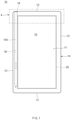
- an electronic device 10 may include a housing 14 having a first surface 11 facing a first direction and a second surface 12 facing a second direction, and a display module 20 mounted in the housing 14.
- the housing 14 may include the first surface 11 facing the first direction, the second surface 12 facing the second direction opposite to the first direction, and a lateral surface 13 surrounding at least part of a space between the first surface 11 and the second surface 12.
- the display module 20 may be mounted in the housing 14 to display an image, text, a video, or the like.
- the display module 20 may have a front surface on which an image, text, or a video is displayed and a rear surface opposite to the front surface. Part of the front surface of the display module 20 may be exposed in the direction toward the first surface 11 of the housing 14, and a screen 15 may be disposed on a front surface of the electronic device 10.
- the screen 15 of the electronic device 10 may be implemented with a touch screen having a touch screen function, and the touch screen may be implemented by mounting a touch screen panel on the front surface of the display module 20.
- the housing 14 may have a storage space 18 formed on a side thereof, in which a stylus pen 100 configured to touch the touch screen of the display module 20 is removably received.
- the storage space 18 may extend a specified length along an edge of the housing 14.
- the storage space 18 may be closed at one end thereof within the housing 14, and an opening 19 exposed outside the housing 14 may be formed at an opposite end of the storage space 18.
- the storage space 18 may be formed in a structure corresponding to the shape and size of the stylus pen 100 to facilitate the storage of the stylus pen 100.
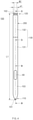
- the stylus pen 100 may extend in the direction of an axis 103 to have a length by which the entirety of the stylus pen 100 is received in the storage space 18 of the housing 14.
- the stylus pen 100 may have a first end portion 110 and a second end portion 120.
- a first end surface of the first end portion 110 may include a touch tip 101, and the second end portion 120 may include a cap 150.
- the first end portion 110 and the second end portion 120 may be opposite to each other on the axis 103 of the stylus pen 100.
- a second end surface 102 of the second end portion 120 of the stylus pen 100 and part of the lateral surface 13 of the housing 14 may be arranged in substantially the same plane, as illustrated in FIGS. 1 to 3 . If the cap 150 is installed in the second end portion 120 of the stylus pen 100 and the stylus pen 100 is completely received in the storage space 18 of the housing 14, the second end surface 102 of the cap 150 and part of the lateral surface 13 of the housing 14 may be arranged in the same plane.
- the cap 150 is arranged with the lateral surface 13 of the housing 14 in the same plane as described above, the cap 150 may be formed of the same material as the housing 14 in consideration of the appearance thereof.
- the cap 150 may also be formed of a metal material.
- one or more radiators 71 constituting an antenna may be provided on the lateral surface 13 of the housing 14, and at least one cut-off portion 72 may be formed at opposite ends of the radiators 71.
- the at least one cut-off portion 72 may be formed on the lateral surface 13 of the housing 14 to intersect with the first surface 11 and the second surface 12.
- the cap 150 may be disposed between the cut-off portions 72 to minimize an influence on the set frequency of the antenna.
- the storage space 18 in which to receive the stylus pen 100 may be disposed between the cut-off portions 72.
- the storage space 18 may be disposed adjacent to any one cut-off portion 72 in consideration of interference with the display module 20.
- the cap 150 may have a first width w1 and may be coupled to a mounting member 160 having a second width w2 smaller than the first width w1 of the cap 150.
- the mounting member 160 may correspond to a neck part of the stylus pen 100 that has a smaller width than the cap 150.
- the mounting member 160, together with the cap 150, may be movably installed in the second end portion 120 of the stylus pen 100.
- the second end portion 120 of the stylus pen 100 may have a separation groove, into which a user's finger is able to be inserted, owing to the first width w1 of the cap 150 and the second width w2 of the mounting member 160, which corresponds to the neck part, and the separation groove may allow the user to easily separate the stylus pen 100.
- a coupling rib 151 may extend from one surface of the cap 150 in one direction, and the coupling rib 151 of the cap 150 may be inserted into a cap holder 153.
- the cap holder 153 may be coupled to the mounting member 160 through press-fit, bonding, or the like.
- a stopper 152 may be formed on an end portion of the coupling rib 151, and an insertion recess 155 into which the coupling rib 151 is inserted may be formed in the cap holder 153. Accordingly, the coupling rib 151 of the cap 150 may be inserted into the insertion recess 155 of the cap holder 153.
- the cap holder 153 may include a pair of legs 157 extending in one direction, and the legs 157 of the cap holder 153 may be inserted into a coupling recess 167 of the mounting member 160 and may be coupled to the mounting member 160 through insertion-coupling, screw-coupling, an adhesive, or the like.
- the legs 157 of the cap holder 153 may be bonded to the coupling recess 167 of the mounting member 160 through an adhesive, and thus the cap holder 153 may be very firmly coupled to the mounting member 160.
- the extending legs 157 of the cap holder 153 may be coupled to an inner surface of the coupling recess 167 of the mounting member 160 with a large contact area therebetween, and thus the cap holder 153 may be very firmly coupled to the mounting member 160.
- a coupling protrusion 161 may protrude from one end portion of the mounting member 160, and a coupling hook 163 may be formed on a distal end portion of the coupling protrusion 161.
- the above-described coupling recess 167 may be formed in an opposite end portion of the mounting member 160.
- the cap 150 is coupled to the stylus pen 100 through the coupling rib 151, the cap holder 153, the mounting member 160, and the like, it is possible to relatively reduce the thickness of the cap 150.
- the stylus pen 100 includes a pen body 130 extending along the axis 103 and a variable length unit 200 installed in the pen body 130 to vary the length of the stylus pen 100.
- the pen body 130 extends along the axis 103 and has an inner space formed therein, in which various components are installed.
- the touch tip 101 is installed in one end portion of the pen body 130, and the cap 150 is installed in an opposite end portion of the pen body 130 so as to be movable along the axis 103.
- the length of the stylus pen 100 may be varied depending on a movement of the cap 150.
- the stylus pen 100 may have a first length LI, which is an initial length, if the second end surface 102 of the cap 150 is located at a first position P1, where the second end surface 102 is arranged with the lateral surface 13 of the electronic device 10 in the same plane, in the state in which the stylus pen 100 is received in the storage space 18 of the electronic device 10.
- the stylus pen 100 may change in length to a second length L2 if the cap 150 is moved inward toward the storage space 18 by an external force applied thereto (e.g., by pressing the cap 150 by the user) to reach a second position P2, where the cap 150 makes contact with a second body 132 of the pen body 130.
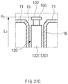
- the stylus pen 100 may change in length to a third length L3 if the cap 150 is located at a third position P3, where the cap 150 protrudes outside the storage space 18 of the housing 14, by the variable length unit 200, which will be described below.
- the length of the stylus pen 100 according to the present invention may be diversely changed to the first length LI, the second length L2, or the third length L3 by the movement of the movable cap 150 (e.g., to the first position P1, the second position P2, or the third position P3).
- the cap 150 of the stylus pen 100 protrudes to the outside, as illustrated in FIG. 27C , in the state in which the stylus pen 100 is received in the storage space 18 of the electronic device 10, the stylus pen 100 may be easily separated from the storage space 18 by the user.
- the pen body 130 includes a first body 131 in which the touch tip 101 is installed and the second body 132 in which the variable length unit 200 is installed.
- the touch tip 101 may be installed to protrude a predetermined length from one end portion of the first body 131 and may be configured to touch the touch screen 15 of the electronic device 10.
- the touch tip 101 may be formed of a soft material, such as rubber, conductive foam, or the like, and may have a curved surface to prevent damage to the touch screen 15 of the electronic device 10.
- a printed circuit board (PCB) 51 having electronic components mounted thereon for performing various functions, such as note taking, drawing, painting, scroll, eraser, right click, and the like, other than a touch is disposed in an inner space of the pen body 130 adjacent to the touch tip 101, that is, in an inner space of the first body 131, and one or more switching components 52 configured to perform functions are mounted on the printed circuit board 51.
- a function button 60 configured to turn on/off the switching components 52 is provided on the outside of the first body 131.
- a reinforcing bracket 65 is attached to the bottom of the function button 60 through a fastener, hook-coupling, or the like, and the bottom of the function button 60 is bonded to an upper surface of the reinforcing bracket 65 through an adhesive.
- the reinforcing bracket 65 is installed on the inside of the first body 131 and includes a free end portion 66 not being anchored to the first body 131 and an anchored end portion 67 located on the opposite side to the free end portion 66.
- the free end portion 66 is disposed adjacent to the function button 60, and the anchored end portion 67 is fixedly installed on the inside of the first body 131. Accordingly, the free end portion 66 moves up and down relative to the anchored end portion 67, and thus the reinforcing bracket 65 facilitates an on/off operation of the function button 60 and ensures the rigidity of the function button 60.
- a protrusion 68 is formed on the bottom of the reinforcing bracket 65 to make contact with the switching components 52. The protrusion 68 facilitates on/off operations of the switching components 52.
- the variable length unit 200 may be installed in an inner space adjacent to an opposite end portion of the pen body 130, that is, inside the second body 132 and may be configured to vary the length of the stylus pen 100. If an external force is applied to the stylus pen 100 in the state in which the stylus pen 100 is received in the storage space 18 of the housing 14, the variable length unit 200 may allow one side of the stylus pen 100 to protrude outside the storage space 18 of the housing 14. If external pressure is applied to the cap 150 (e.g., the cap 150 is pressed), the variable length unit 200 may move the cap 150 in the direction of the axis 103. Accordingly, the length of the stylus pen 100 may be changed to, for example, the first length LI, the second length L2, or the third length L3.
- the variable length unit 200 includes a shaft 250 movable in the pen body 130 in the direction of the axis 103 and an elastic member 260 elastically supporting the shaft 250.
- the shaft 250 is installed in an inner space adjacent to the opposite end portion of the pen body 130, that is, in an inner space of the second body 132 so as to be movable along the axis 103.
- One end portion of the second body 132 is coupled to the opposite end portion of the first body 131.
- a coupling part 135 is formed on the opposite end portion of the first body 131, and the one end portion of the second body 132 is coupled to the coupling part 135 of the first body 131 through press-fit, bonding, or the like.
- corrugated portions corresponding to each other may be formed on an outer surface of the coupling part 135 of the first body 131 and an inner surface of the one end portion of the second body 132 to strengthen the coupling force between the first body 131 and the second body 132.
- the second body 132 may be integrally formed with the opposite end portion of the first body 131.
- the elastic member 260 is mounted on one end portion of the shaft 250, and the shaft 250 is elastically supported by the elastic member 260.
- the cap 150 is connected to an opposite end portion of the shaft 250 through the cap holder 153 and the mounting member 160 described above. Accordingly, if an external force is applied to the cap 150, the shaft 250 is moved in the direction of the axis 103 by the elastic force of the elastic member 260, and the cap 150 protrudes from the opening 19 of the storage space 18 in the housing 14 to the outside.
- the shaft 250 is installed such that the shaft 250 is linearly moved in the second body 132 by the elastic member 260 and a cam mechanism 300.
- the cam mechanism 300 moves the shaft 250 in cooperation with the elastic member 260.
- the cam mechanism 300 includes a first moving member 310 configured to linearly move in the second body 132 when an external force is applied to the cap 150 in the direction of the axis 103, a second moving member 320 configured to linearly move and rotate in conjunction with the linear motion of the first moving member 310, and a guide structure 330 provided in the second body 132 to guide the movement of the first moving member 310 and the second moving member 320.
- the first moving member 310 has a cylindrical structure with a predetermined outer diameter.
- the first moving member 310 includes at least one first cam surface 315 on one end portion thereof, and the first cam surface 315 includes ridge portions and valley portions.
- the first moving member 310 may also include a plurality of first cam surfaces 315 following one after another in the circumferential direction.
- An opposite end portion of the first moving member 310 may be connected to the cap 150 through the mounting member 160 and the cap holder 153 described above.
- the hook 163 of the coupling protrusion 161 may be coupled to a coupling hole 319 of the first moving member 310 by a snap-fit connection after the coupling protrusion 161 of the mounting member 160 is inserted into the first moving member 310, and thus the mounting member 160 may be very firmly coupled to the opposite end portion of the first moving member 310. Since the first moving member 310 is connected to the cap 150 through the mounting member 160 and the cap holder 153 as described above, the first moving member 310, together with the cap 150, may linearly move along the axis 103 when the cap 150 is pressed.
- the opposite end portion of the shaft 250 may be connected to the first moving member 310. Accordingly, the shaft 250 may be connected to the cap 150 through the first moving member 310, the mounting member 160, and the cap holder 153, and thus the first moving member 310 may be configured to linearly move together with the cap 150.
- the second moving member 320 is configured to linearly move and rotate in conjunction with the linear motion of the first moving member 310.
- the second moving member 320 is configured such that an elastic force is applied to the second moving member 320 by the elastic member 260, which is disposed in a case, in the direction of the axis 103.
- the shaft 250 passes through the second moving member 320 and is coupled, at one side thereof, to the second moving member 320 through a fixing ring 258, such as an E-ring, a C-ring, or the like, and the fixing ring 258 of the shaft 250 is configured to withstand the elastic force of the elastic member 260.
- the elastic member 260 may be installed between the coupling part 135 of the first body 131 and the fixing ring 258 of the shaft 250.
- the coupling part 135 may have an insertion recess 136 formed therein.
- One end portion of the elastic member 260 may be inserted into and supported by the insertion recess 136 of the coupling part 135, and an opposite end portion of the elastic member 260 may be supported on the fixing ring 258 of the shaft 250.
- the elastic member 260 may be configured to apply an elastic force to the second moving member 320 and the shaft 250 in the direction toward the outside from the second body 132.
- the second moving member 320 has one or more second cam surfaces 325 that are complementary to and mate with the first cam surface 315 of the first moving member 310, and the second cam surfaces 325 have ridge portions and valley portions.
- the second moving member 320 may also have a plurality of second cam surfaces 325 following one after another in the circumferential direction.
- the first moving member 310 may move downward, and the first cam surface 315 of the first moving member 310 and the second cam surfaces 325 of the second moving member 320 may make contact with each other. Accordingly, the second cam surfaces 325 of the second moving member 320 may slide relative to the first cam surface 315 of the first moving member 310 to rotate about the axis 103.
- the guide structure 330 may include a linear guide part 331 configured to guide linear motion of the first moving member 310 and the second moving member 320 and a rotary guide part 333 configured to guide rotation of the second moving member 320 and stop the rotation of the second moving member 320.
- the linear guide part 331 may extend from the inside of the second body 132 along the axis 103 to guide the linear motion of the first moving member 310 and the second moving member 320.
- the linear guide part 331 may be implemented with one or more guide rails 332 protruding inward from the inside of the case.
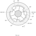
- the first moving member 310 may have one or more first guide grooves 317 formed on the outer surface thereof and inserted into and guided by the guide rails 332, and the second moving member 320 may have one or more second guide grooves 327 formed on the outer surface thereof and inserted into and guided by the guide rails 332.
- the first moving member 310 may have one or more first guide grooves 317 formed on the outer surface thereof and inserted into and guided by the guide rails 332
- the second moving member 320 may have one or more second guide grooves 327 formed on the outer surface thereof and inserted into and guided by the guide rails 332.
- the plurality of guide rails 332 may be spaced circumferentially apart from one another on the inside of the second body 132, and the plurality of first and second guide grooves 317 and 328 may be formed to correspond to the plurality of guide rails 332.
- the rotary guide part 333 may be implemented with inclined surfaces 335 provided at lower ends of the guide rails 332, and the second cam surfaces 325 of the second moving member 320 may have a saw-tooth form to correspond to the inclined surfaces 335. Accordingly, when the inclined surfaces 335 make contact with inclined portions of the second cam surfaces 325, rotation of the second moving member 320 may be effectively guided, and when the inclined surfaces 335 are inserted into the valley portions of the second cam surfaces 325, the second moving member 320 may stop rotating.
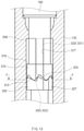
- the first moving member 310 and the second moving member 320 may be spaced apart downward from a restriction step 208 by a predetermined distance, as illustrated in FIG. 9 .
- the first guide grooves 317 of the first moving member 310 may be mounted on the guide rails 332, as illustrated in FIG. 10
- the second guide grooves 327 of the second moving member 320 may not be mounted on the guide rails 332, as illustrated in FIG. 11 .
- the inclined surfaces 335 may be stopped by the valley portions of the second cam surfaces 325 of the second moving member 320, and thus the second moving member 320 may stop rotating. As a result, the cap 150 may be maintained at the first position P1.
- the cap 150 may move to the second position P2, as illustrated in FIG. 27B , where the cap 150 makes contact with the upper end of the second body 132 and, as illustrated in FIG. 12 , the first moving member 310 and the second moving member 320 may further move downward than in FIG. 9 (see arrow S1).
- the second guide grooves 327 of the second moving member 320 may move below the lower ends of the guide rails 332, that is, the inclined surfaces 335 in the state in which the second guide grooves 327 are not mounted on the guide rails 332.
- the second cam surfaces 325 of the second moving member 320 may be spaced apart from the inclined surfaces 335, and thus the second moving member 320 may be in a rotatable state.
- the second cam surfaces 325 of the second moving member 320 and the first cam surface 315 of the first moving member 310 may slide relative to each other, and thus the second moving member 320 may rotate about the axis 103 (see the direction of arrow T).
- the second moving member 320 since the inclined surfaces 335 make contact with the inclined sections of the second cam surfaces 325, the second moving member 320 may more effectively rotate.
- the second cam surfaces 325 of the second moving member 320 and the first cam surface 315 of the first moving member 310 may continue to slide relative to each other, and thus the second guide grooves 327 of the second moving member 320 may be mounted on the guide rails 332 of the second body 132, as illustrated in FIG. 15 .
- the elastic force of the elastic member 260 may be applied to the second moving member 320, and the first moving member 310 and the second moving member 320 may move upward together, as illustrated in FIG. 17 (see arrow S2). Accordingly, the cap 150 connected to the first moving member 310 may move to the third position P3, as illustrated in FIG. 27C , where the cap 150 protrudes outside the storage space 18 of the housing 14, and the cap 150 may remain in the state in which the cap 150 has protruded from the storage space 18 of the housing 14.
- the linear guide part 331 may be implemented with one or more guide grooves 334 formed on the inside of the second body 132.
- the first moving member 310 may have, on the outside thereof, one or more first guide protrusions 319 inserted into and guided by the guide grooves 334
- the second moving member 320 may have, on the outside thereof, one or more second guide protrusions 329 inserted into and guided by the guide grooves 334.
- Upper ends of the second guide protrusions 329 may be formed in a structure corresponding to the shape of the second cam surfaces 325.
- the plurality of guide grooves 334 may be spaced circumferentially apart from one another on the inside of the second body 132, and the plurality of first guide protrusions 319 and the plurality of second guide protrusions 329 may be formed to correspond to the plurality of guide grooves 334.
- the rotary guide part 333 may be implemented with a plurality of saw-tooth forms 336 provided at lower ends of the guide grooves 334.
- the plurality of saw-tooth forms 336 may be continuously formed in the circumferential direction to guide rotation of the second guide protrusions 329 of the second moving member 320. Accordingly, if the second guide protrusions 329 of the second moving member 320 are separated from the guide grooves 334 of the second body 132, the second guide protrusions 329 may make contact with the plurality of saw-tooth forms 336, and thus rotation of the second moving member 320 may be guided, and if upper ends of the second guide protrusions 329 of the second moving member 320 are inserted into valley portions of the saw-tooth forms 336, the second moving member 320 may stop rotating.
- the second moving member 320 may stop rotating and may be stationary at a specific position if the upper ends of the second guide protrusions 329 are inserted into the valley portions of the saw-tooth forms 336 after the second guide protrusions 329 of the second moving member 320 are separated from the guide grooves 334.
- the first moving member 310 and the second moving member 320 may be spaced apart downward from the restriction step 208 by a predetermined distance, as illustrated in FIGS. 18 and 19 .
- the first guide protrusions 319 of the first moving member 310 may be inserted into the guide grooves 334 of the second body 132 and, as illustrated in FIGS.
- the upper ends of the second guide protrusions 329 of the second moving member 320 may be stopped by the valley portions of the saw-tooth forms 336 so that the second moving member 320 may be prevented from rotating and thus the cap 150 may remain at the position PI.
- the cap 150 may move to the second position P2, as illustrated in FIG. 27B , where the cap 150 makes contact with the upper end of the second body 132 and, as illustrated in FIGS. 22 and 23 , the first moving member 310 and the second moving member 320 may further move downward than in FIGS. 18 and 19 (see arrow S1).
- the second guide protrusions 329 of the second moving member 320 move below the lower ends of the guide grooves 334, that is, the saw-tooth forms 336
- the upper ends of the second guide protrusions 329 of the second moving member 320 may be separated from the valley portions of the saw-tooth forms 336, and thus the second moving member 320 may be in a rotatable state.
- the second cam surfaces 325 of the second moving member 320 and the first cam surface 315 of the first moving member 310 may slide relative to each other, and thus the second moving member 320 may rotate about the axis 103 (see the direction of arrow T in FIG. 21 ).
- the second moving member 320 since inclined sections of the saw-tooth forms 336 make contact with inclined sections of the second cam surfaces 325, the second moving member 320 may more effectively rotate.
- the second cam surfaces 325 of the second moving member 320 and the first cam surface 315 of the first moving member 310 may continue to slide relative to each other, and thus the second guide protrusions 329 of the second moving member 320 may be inserted into the guide grooves 334, as illustrated in FIGS. 24 and 25 .
- the elastic force of the elastic member 260 may be applied to the second moving member 320, and the first moving member 310 and the second moving member 320 may move upward together, as illustrated in FIG. 26 (see arrow S2). Accordingly, the cap 150 connected to the first moving member 310 may move to the third position P3, as illustrated in FIG. 27C , where the cap 150 protrudes outside the storage space 18 of the housing 14, and the cap 150 may remain in the state in which the cap 150 has protruded from the storage space 18 of the housing 14.
- the stylus pen 100 includes a restriction structure configured to limit a movement of some elements of the variable length unit 200 and/or the cap 150 when the length of the stylus pen 100 is varied by the variable length unit 200.
- a step 318 may be formed on a side of the first moving member 310, and the restriction step 208 by which the step 318 of the first moving member 310 is stopped may be formed on the inside of the second body 132.
- the restriction step 208 may protrude inward from the inside of the second body 132 in the radial direction. Accordingly, when the first moving member 310 moves in the direction of arrow V1 in FIG.
- the step 318 of the first moving member 310 is stopped by the restriction step 208 so that the movement of the first moving member 310 is limited and a movement of the cap 150 connected to the first moving member 310 is also limited.
- the protruding length of the cap 150 is restricted to a set range.
- the second moving member 320 is secured to one side of the shaft 250 through the fixing ring 258, as illustrated in FIGS. 5 to 7 , and the fixing ring 258 is elastically supported by the elastic member 260, when the second moving member 320 moves in the direction of arrow V2 in FIG. 7 , the movement of the second moving member 320 is limited by the elastic force of the elastic member 260.
- the shaft 250 passes through the first moving member 310 and the second moving member 320, the second moving member 320 is secured to one side of the shaft 250, and the first moving member 310 is connected to the cap 150 through the mounting member 160 and the cap holder 153. Accordingly, the first moving member 310 and the second moving member 320 may move relative to each other along the axis 103.
- the first moving member 310 and the second moving member 320 may move relative to each other in the directions (arrows V1 and V2 in FIG. 7 ) in which the first and second moving members 310 and 320 become closer to each other or in the directions (arrows X1 and X2 in FIG. 7 ) in which the first and second moving members 310 and 320 move away from each other.
- the restriction structure may further include a restriction unit 400 configured to restrict the relative distance between the first moving member 310 and the second moving member 320 to a predetermined range.
- the restriction unit 400 includes a connecting member 410 configured to elastically connect the first moving member 310 and the second moving member 320.
- the connecting member 410 is configured to elastically connect the shaft 250 and the first moving member 310.
- the second moving member 320 is secured to the shaft 250 through the fixing ring 258, the opposite end portion of the shaft 250 is inserted into the first moving member 310, and the shaft 250 and the first moving member 310 are elastically connected together through the connecting member 410.
- the connecting member 410 is formed of an elastic material, such as a spring, rubber, or the like, which is extensible between the shaft 250 and the first moving member 310 along the axis 103.
- the shaft 250 may have a stopper 251 protruding outward from the opposite end portion thereof in the radial direction, the opposite end portion of the shaft 250 may be inserted into the first moving member 310, and the first moving member 310 may have a support step 316 formed on the inside thereof.
- the connecting member 410 may be installed between the stopper 251 of the shaft 250 and the support step 316 of the first moving member 310, and thus the shaft 250 and the first moving member 310 may be elastically connected together.
- the first moving member 310 and the second moving member 320 may be elastically connected along the axis 103 through the connecting member 410. Since the connecting member 410 is formed of an elastic material elastically connecting the first moving member 310 and the shaft 250 in the direction of the axis 103 as described above, the first moving member 310 may be restricted to maintain a predetermined distance from the second moving member 320.
- a structure in which the distance between the first moving member 310 and the second moving member 320 is restricted to a predetermined range will be described below in detail with reference to FIG. 7 .
- the first moving member 310 may be restricted toward the shaft 250 and the second moving member 320 by an elastic force that the connecting member 410 applies to the first moving member 310 in the direction of arrow XI, and thus the distance between the first moving member 310 and the second moving member 320 may be maintained with a predetermined range.
- the second moving member 320 may be restricted toward the first moving member 310 by an elastic force that the connecting member 410 applies to the second moving member 320 in the direction of arrow X2, and thus the distance between the first moving member 310 and the second moving member 320 may be maintained with a predetermined range.
- the cap 150 connected to the first moving member 310 may be effectively prevented from randomly moving to the outside from the opening 19 of the storage space 18, and thus the cap 150 may stably remain at the first position PI (see FIG. 27A ) where the cap 150 is arranged with the lateral surface 13 of the housing 14 in the same plane and at the third position P3 (see FIG. 27B ) where the cap 150 protrudes from the lateral surface 13 of the housing 14.
- the restriction unit 400 may be configured to allow a relative motion between the first moving member 310 and the second moving member 320 while maintaining contact between the first cam surface 315 of the first moving member 310 and the second cam surfaces 325 of the second moving member 320.
- the restriction unit 400 may be configured to allow a relative motion between the first moving member 310 and the second moving member 320 while maintaining contact between the first cam surface 315 of the first moving member 310 and the second cam surfaces 325 of the second moving member 320.
- the restriction unit 400 may be configured to allow a relative motion between the first moving member 310 and the second moving member 320 while maintaining contact between the first cam surface 315 of the first moving member 310 and the second cam surfaces 325 of the second moving member 320.
- the connecting member 410 may be formed of an elastic material, such as a spring, rubber, or the like, which has a modulus of elasticity sufficient to maintain contact between the first cam surface 315 and the second cam surfaces 325. Since the connecting member 410 is configured to maintain contact between the first cam surface 315 of the first moving member 310 and the second cam surfaces 325 of the second moving member 320, as described above, the first cam surface 315 of the first moving member 310 and the second cam surfaces 325 of the second moving member 320 may more effectively slide relative to each other.
- an elastic material such as a spring, rubber, or the like
- an electronic device may include a housing that includes a first surface facing a first direction, a second surface facing a second direction opposite to the first direction, and a lateral surface surrounding at least part of a space formed between the first surface and the second surface, an opening formed in one portion of the lateral surface of the housing, a storage space extending from the opening, with an axis as a center of the storage space, and a stylus pen that includes a first end surface including a touch tip and a second end surface opposite to the first end surface and has a length by which the entirety of the stylus pen is received in the storage space, the second end surface being arranged with another portion of the lateral surface of the housing in substantially the same plane in a case where the entirety of the stylus pen is received in the storage space, and the stylus pen being configured to be removable from the storage space.
- the second end surface of the stylus pen may be configured to protrude outside the storage space from the opening in a direction of the axis in response to external pressure.
- an electronic device may include a housing that includes a first surface facing a first direction, a second surface facing a second direction opposite to the first direction, and a lateral surface surrounding at least part of a space formed between the first surface and the second surface, an opening formed in one portion of the lateral surface of the housing, a storage space extending from the opening, and a stylus pen that includes a first end portion including a touch tip and a second end portion opposite to the first end portion and has a length by which the entirety of the stylus pen is received in the storage space, the second end portion being arranged with another portion of the lateral surface of the housing in substantially the same plane in a case where the entirety of the stylus pen is received in the storage space, and the stylus pen being configured to be removable from the storage space.
- the second end portion of the stylus pen may include a cap configured to be pressed toward the storage space from outside the housing.
- the cap may have a first width when viewed from above the storage space, and the stylus pen may have a second width smaller than the first width when viewed from above the storage space.
- the stylus further includes a shaft that is movable into an inner space of the stylus pen, and the cap is connected to the shaft.
- the stylus pen further includes an elastic member configured to elastically support the shaft.
- the cap may protrude outside the opening according to a movement of the shaft in a case where the cap is pressed.
- one or more radiators constituting an antenna may be provided on a lateral surface of the housing, a cut-off portion may be provided on at least one end of the radiators, and the storage space may be disposed adjacent to the cut-off portion.
- the first structure includes a shaft movable along the axis in an inner space adjacent to the opposite end of the pen body.
- the first structure further includes an elastic member configured to elastically support the shaft.
- the first structure further includes a cam mechanism configured to move the shaft along the axis in cooperation with the elastic member.
- the cam mechanism includes a first moving member configured to linearly move along the axis as an external force is applied to the cap, and a second moving member configured to rotate while linearly moving together with the linear movement of the first moving member.
- the first moving member may have one or more cam surfaces
- the second moving member may have one or more second cam surfaces that slide relative to the first cam surfaces
- the cam mechanism may further include a guide structure configured to guide the movement of the first moving member and the second moving member.
- the guide structure may include a linear guide part provided on the inner surface of the pen body to guide the linear movement of the first moving member and the second moving member; and a rotary guide part configured to guide the rotary motion of the second moving member.
- the first moving member is connected to the cap.
- the second structure includes a restriction step configured to limit a movement of at least one of the cap and the first moving member.
- the second structure further includes a restriction unit configured to limit a relative moving distance between the first moving member and the second moving member.
- the restriction unit includes a connecting member configured to elastically connect the first moving member and the second moving member.
- FIG. 30 is a block diagram of an electronic device 3001 according to various embodiments.
- the electronic device 3001 may include all or a part of the electronic device in which the stylus pen 100 is removably received, as described above.
- the electronic device 3001 may include at least one processor (e.g., application processor (AP)) 3010, a communication module 3020, a subscriber identification module 3029, a memory 3030, a sensor module 3040, an input device 3050, a display module 3060, an interface 3070, an audio module 3080, a camera module 3091, a power management module 3095, a battery 3096, an indicator 3097, and a motor 3098.
- AP application processor
- the processor 3010 may drive, for example, an operating system (OS) or an application program to control a plurality of hardware or software components connected thereto and may process and compute a variety of data.
- the processor 3010 may be implemented with, for example, a system on chip (SoC).
- SoC system on chip
- the processor 3010 may include a graphic processing unit (GPU) (not shown) and/or an image signal processor (not shown).
- the processor 3010 may include at least some (e.g., a cellular module 3021) of the components shown in FIG. 30 .
- the processor 3010 may load a command or data received from at least one of other components (e.g., a non-volatile memory) into a volatile memory to process the data and may store various data in a non-volatile memory.
- the communication module 3020 may include, for example, the cellular module 3021, a wireless-fidelity (Wi-Fi) module 3022, a Bluetooth (BT) module 3023, a global navigation satellite system (GNSS) module 3024 (e.g., a GPS module, a Glonass module, a Beidou module, or a Galileo module), a near field communication (NFC) module 3025, an MST module 3026, and a radio frequency (RF) module 3027.
- Wi-Fi wireless-fidelity
- BT Bluetooth
- GNSS global navigation satellite system
- NFC near field communication
- MST MST module
- RF radio frequency
- the cellular module 3021 may provide, for example, a voice call service, a video call service, a text message service, or an Internet service, and the like through a communication network. According to an embodiment of the present disclosure, the cellular module 3021 may identify and authenticate the electronic device 3001 in a communication network using the SIM 3029 (e.g., a SIM card). According to an embodiment of the present disclosure, the cellular module 3021 may perform at least part of functions which may be provided by the processor 3010. According to an embodiment of the present disclosure, the cellular module 3021 may include a communication processor (CP).
- CP communication processor
- the Wi-Fi module 3022, the BT module 3023, the GNSS module 3024, the NFC module 3025, or the MST module 3026 may include, for example, a processor for processing data transmitted and received through the corresponding module. According to various embodiments of the present disclosure, at least some (e.g., two or more) of the cellular module 3021, the Wi-Fi module 3022, the BT module 3023, the GNSS module 3024, the NFC module 3025, or the MST module 3026 may be included in one integrated chip (IC) or one IC package.
- IC integrated chip
- the RF module 3027 may transmit and receive, for example, a communication signal (e.g., an RF signal).
- a communication signal e.g., an RF signal
- the RF module 3027 may include, for example, a transceiver, a power amplifier module (PAM), a frequency filter, or a low noise amplifier (LNA), or an antenna, and the like.
- PAM power amplifier module
- LNA low noise amplifier
- at least one of the cellular module 3021, the Wi-Fi module 3022, the BT module 3023, the GNSS module 3024, the NFC module 3025, or the MST module 3026 may transmit and receive an RF signal through a separate RF module.
- the SIM 3029 may include, for example, a card which includes a SIM and/or an embedded SIM.
- the SIM 3029 may include unique identification information (e.g., an integrated circuit card identifier (ICCID)) or subscriber information (e.g., an international mobile subscriber identity (IMSI)).
- ICCID integrated circuit card identifier
- IMSI international mobile subscriber identity
- the memory 3030 may include, for example, an embedded memory 3032 or an external memory 3034.
- the embedded memory 3032 may include at least one of, for example, a volatile memory (e.g., a dynamic random access memory (DRAM), a static RAM (SRAM), a synchronous dynamic RAM (SDRAM), and the like), or a non-volatile memory (e.g., a one-time programmable read only memory (OTPROM), a programmable ROM (PROM), an erasable and programmable ROM (EPROM), an electrically erasable and programmable ROM (EEPROM), a mask ROM, a flash ROM, a flash memory (e.g., a NAND flash memory or a NOR flash memory, and the like), a hard drive, or a solid state drive (SSD)).
- a volatile memory e.g., a dynamic random access memory (DRAM), a static RAM (SRAM), a synchronous dynamic RAM (SDRAM), and the like
- the external memory 3034 may include a flash drive, for example, a compact flash (CF), a secure digital (SD), a micro-SD, a mini-SD, an extreme digital (xD), a multimedia car (MMC), or a memory stick, and the like.
- the external memory 3034 may operatively and/or physically connect with the electronic device 3001 through various interfaces.
- the security module 3036 may be a module which has a relatively higher secure level than the memory 3030 and may be a circuit which stores secure data and guarantees a protected execution environment.
- the security module 3036 may be implemented with a separate circuit and may include a separate processor.
- the security module 3036 may include, for example, an embedded secure element (eSE) which is present in a removable smart chip or a removable SD card or is embedded in a fixed chip of the electronic device 3001.
- eSE embedded secure element
- the security module 3036 may be driven by an OS different from the OS of the electronic device 3001.
- the security module 3036 may operate based on a java card open platform (JCOP) OS.
- JCOP java card open platform
- the sensor module 3040 may measure, for example, a physical quantity or may detect an operation state of the electronic device 3001, and may convert the measured or detected information to an electric signal.
- the sensor module 3040 may include at least one of, for example, a gesture sensor 3040A, a gyro sensor 3040B, a barometric pressure sensor 3040C, a magnetic sensor 3040D, an acceleration sensor 3040E, a grip sensor 3040F, a proximity sensor 3040G, a color sensor 3040H (e.g., red, green, blue (RGB) sensor), a biometric sensor 30401, a temperature/humidity sensor 3040J, an illumination sensor 3040K, or an ultraviolet (UV) sensor 3040M.
- the sensor module 3040 may further include, for example, an e-nose sensor (not shown), an electromyography (EMG) sensor (not shown), an electroencephalogram (EEG) sensor (not shown), an electrocardiogram (ECG) sensor (not shown), an infrared (IR) sensor (not shown), an iris sensor (not shown), and/or a fingerprint sensor (not shown), and the like.
- the sensor module 3040 may further include a control circuit for controlling at least one or more sensors included therein.
- the electronic device 3001 may further include a processor configured to control the sensor module 3040, as part of the processor 3010 or to be independent of the processor 3010. While the processor 3010 is in a sleep state, the electronic device 3001 may control the sensor module 3040.
- the input device 3050 may include, for example, a touch panel 3052, a (digital) pen sensor 3054, a key 3056, or an ultrasonic input device 3058.
- the touch panel 3052 may use at least one of, for example, a capacitive type, a resistive type, an infrared type, or an ultrasonic type.
- the touch panel 3052 may further include a control circuit.
- the touch panel 3052 may further include a tactile layer and may provide a tactile reaction to a user.
- the (digital) pen sensor 3054 may be, for example, part of the touch panel 3052 or may include a separate sheet for recognition.
- the key 3056 may include, for example, a physical button, an optical key, or a keypad.
- the ultrasonic input device 3058 may allow the electronic device 3001 to detect a sound wave using a microphone (e.g., a microphone 3088) and to verify data through an input tool generating an ultrasonic signal.
- the display 3060 may include a panel 3062, a hologram device 3064, or a projector 3066.
- the panel 3062 may be implemented to be, for example, flexible, transparent, or wearable.
- the panel 3062 and the touch panel 3052 may be integrated into one module.
- the hologram device 3064 may show a stereoscopic image in a space using interference of light.
- the projector 3066 may project light onto a screen to display an image.
- the screen may be positioned, for example, inside or outside the electronic device 3001.
- the display 3060 may further include a control circuit for controlling the panel 3062, the hologram device 3064, or the projector 3066.
- the interface 3070 may include, for example, a high-definition multimedia interface (HDMI) 3072, a universal serial bus (USB) 3074, an optical interface 3076, or a D-subminiature 3078.
- the interface 3070 may be included in the communication interface. Additionally or alternatively, the interface 3070 may include, for example, a mobile high definition link (MHL) interface, an SD card/multimedia card (MMC) interface, or an infrared data association (IrDA) standard interface.
- MHL mobile high definition link
- MMC SD card/multimedia card
- IrDA infrared data association
- the audio module 3080 may convert a sound and an electric signal in dual directions. At least part of components of the audio module 3080 may be included in an input and output interface.
- the audio module 3080 may process sound information input or output through, for example, a speaker 3082, a receiver 3084, an earphone 3086, or the microphone 3088, and the like.
- the camera module 3091 may be a device which captures a still image and a moving image.
- the camera module 3091 may include one or more image sensors (not shown) (e.g., a front sensor or a rear sensor), a lens (not shown), an image signal processor (ISP) (not shown), or a flash (not shown) (e.g., an LED or a xenon lamp).
- image sensors e.g., a front sensor or a rear sensor
- ISP image signal processor
- flash not shown
- the power management module 3095 may manage, for example, power of the electronic device 3001.
- the power management module 3095 may include a power management integrated circuit (PMIC), a charger IC or a battery or fuel gauge.
- the PMIC may have a wired charging method and/or a wireless charging method.
- the wireless charging method may include, for example, a magnetic resonance method, a magnetic induction method, or an electromagnetic method, and the like.
- An additional circuit for wireless charging for example, a coil loop, a resonance circuit, or a rectifier, and the like may be further provided.
- the battery gauge may measure, for example, the remaining capacity of the battery 3096 and voltage, current, or temperature thereof while the battery 3096 is charged.
- the battery 3096 may include, for example, a rechargeable battery or a solar battery.
- the indicator 3097 may display a specific state of the electronic device 3001 or part (e.g., the processor 3010) thereof, for example, a booting state, a message state, or a charging state, and the like.
- the motor 3098 may convert an electric signal into mechanical vibration and may generate vibration or a haptic effect, and the like.
- the electronic device 3001 may include a processing unit (e.g., a GPU) for supporting a mobile TV.
- the processing unit for supporting the mobile TV may process media data according to standards, for example, a digital multimedia broadcasting (DMB) standard, a digital video broadcasting (DVB) standard, or a MediaFLO TM standard, and the like.
- DMB digital multimedia broadcasting
- DVD digital video broadcasting
- MediaFLO TM MediaFLO
- Each of the above-mentioned elements of the electronic device according to various embodiments of the present disclosure may be configured with one or more components, and names of the corresponding elements may be changed according to the type of the electronic device.
- the electronic device according to various embodiments of the present disclosure may include at least one of the above-mentioned elements, some elements may be omitted from the electronic device, or other additional elements may be further included in the electronic device. Also, some of the elements of the electronic device according to various embodiments of the present disclosure may be combined with each other to form one entity, thereby making it possible to perform the functions of the corresponding elements in the same manner as before the combination.
- module used herein may represent, for example, a unit including one of hardware, software and firmware or a combination thereof.
- the term “module” may be interchangeably used with the terms “unit”, “logic”, “logical block”, “component” and “circuit”.
- the “module” may be a minimum unit of an integrated component or may be a part thereof.
- the “module” may be a minimum unit for performing one or more functions or a part thereof.
- the “module” may be implemented mechanically or electronically.
- the “module” may include at least one of an application-specific integrated circuit (ASIC) chip, a field-programmable gate array (FPGA), and a programmable-logic device for performing some operations, which are known or will be developed.
- ASIC application-specific integrated circuit
- FPGA field-programmable gate array
- At least a part of devices (e.g., modules or functions thereof) or methods (e.g., operations) according to various embodiments of the present disclosure may be implemented as instructions stored in a computer-readable storage medium in the form of a program module.
- the processor may perform functions corresponding to the instructions.
- the computer-readable storage medium may be, for example, the memory.
- a computer-readable recording medium may include a hard disk, a floppy disk, a magnetic medium (e.g., a magnetic tape), an optical medium (e.g., CD-ROM, digital versatile disc (DVD)), a magneto-optical medium (e.g., a floptical disk), or a hardware device (e.g., a ROM, a RAM, a flash memory, or the like).
- the program instructions may include machine language codes generated by compilers and high-level language codes that can be executed by computers using interpreters.
- the above-mentioned hardware device may be configured to be operated as one or more software modules for performing operations of various embodiments of the present disclosure and vice versa.
Landscapes
- Engineering & Computer Science (AREA)
- Theoretical Computer Science (AREA)
- General Engineering & Computer Science (AREA)
- Human Computer Interaction (AREA)
- Physics & Mathematics (AREA)
- General Physics & Mathematics (AREA)
- Computer Hardware Design (AREA)
- Casings For Electric Apparatus (AREA)
- Position Input By Displaying (AREA)
- Mechanical Pencils And Projecting And Retracting Systems Therefor, And Multi-System Writing Instruments (AREA)
- Telephone Set Structure (AREA)
Claims (7)
- Système comprenant un appareil électronique et un stylet (100), le stylet étant conçu pour être reçu avec faculté d'extraction dans un espace de réception de l'appareil électronique, le stylet (100) comprenant :un corps de stylet (130) formé eu égard à un axe et comportant une surface extérieure et une surface intérieure, ledit corps de stylet (130) s'étendant selon la direction de l'axe ;un capuchon (150) disposé à une extrémité du corps de stylet ;une première structure conçue pour entrer en contact avec au moins une partie de la surface intérieure du corps de stylet et pour changer de longueur selon la direction de l'axe en réaction à une pression appliquée sur le capuchon (150), la première structure comprenant :une tige (250) déplaçable le long de l'axe (103) dans un espace intérieur adjacent à l'extrémité opposée du corps de stylet (130) ;un élément élastique (260) conçu pour supporter la tige de manière élastique ;un mécanisme à cames (300) conçu pour déplacer la tige (250) le long de l'axe (103) en coopération avec l'élément élastique (260), le mécanisme à cames comprenant :un premier élément mobile (310) qui est conçu pour se déplacer de façon linéaire le long de l'axe (103) tandis qu'une force externe est appliquée sur le capuchon (150), qui est relié au capuchon (150) et dans lequel est insérée une partie terminale de la tige ;un deuxième élément mobile (320) qui est conçu pour tourner tout en se déplaçant de façon linéaire conjointement au mouvement linéaire du premier élément mobile, et qui est fixé à la tige (250) par une bague de fixation (258) ;une deuxième structure conçue pour entrer en contact avec au moins une partie de la première structure et pour limiter le mouvement du capuchon et/ou de la première structure selon la direction de l'axe, comprenant :un épaulement de limitation (208) conçu pour limiter le mouvement du capuchon (150) et/ou du premier élément mobile (310), une partie du premier élément mobile (310) étant arrêtée par l'épaulement de limitation (208) ;une unité de limitation (400) conçue pour limiter la distance de mouvement relative entre le premier élément mobile (310) et le deuxième élément mobile (320), comprenant un élément de liaison (410) conçu pour relier de manière élastique le premier élément mobile (310) à la tige (250), ledit élément de liaison (410) étant extensible entre la tige (250) et le premier élément mobile (310) le long de l'axe (103) et étant conçu pour maintenir un contact entre une surface de came (315) du premier élément mobile (310) et une surface de came (325) du deuxième élément mobile (320) ;une pointe tactile (101) disposée sur une extrémité opposée du corps de stylet ; etune carte de circuit imprimé (PCB, printed circuit board) (51) comprenant un ou plusieurs composants de commutation (25) ;un bouton de fonction conçu pour enclencher et désenclencher les composants de commutation ; etune barre de renfort (65) qui est rattachée sur le dessous du bouton de fonction (60) ;ladite barre de renfort (65) étant installée sur l'intérieur du corps de stylet et comportant une partie terminale libre (66) non accrochée au corps de stylet et une partie terminale accrochée (67) qui est située sur le côté opposé à la partie terminale libre.
- Système selon la revendication 1, dans lequel la tige comprend un butoir (251) faisant saillie à partir de la partie terminale, ledit premier élément mobile possédant un épaulement de support formé sur son intérieur, et ledit élément de liaison étant installé entre le butoir (251) et l'épaulement de support (316).
- Système selon la revendication 1 ou 2, comprenant en outre :
une saillie (68), formée sur le dessous de la barre de renfort pour entrer en contact avec les composants de commutation pour permettre les opérations d'enclenchement et désenclenchement des composants de commutation. - Système selon la revendication 1, 2 ou 3, dans lequel le premier élément mobile (310) présente une ou plusieurs surfaces de came (315), et
dans lequel le deuxième élément mobile présente une ou plusieurs deuxièmes surfaces de came (325) coulissant par rapport aux premières surfaces de came (325). - Système selon la revendication 4, dans lequel le mécanisme à cames (300) comporte en outre :
une structure de guidage (330) conçue pour guider le mouvement du premier élément mobile (310) et du deuxième élément mobile (320). - Système selon la revendication 5, dans lequel la structure de guidage comporte :une partie de guidage linéaire (331) prévue sur la surface intérieure du corps de stylet pour guider le mouvement linéaire du premier élément mobile (310) et du deuxième élément mobile (320), etune partie de guidage en rotation (333) conçue pour guider le mouvement de rotation du deuxième élément mobile (320).
- Système selon l'une quelconque des revendications précédentes, l'appareil électronique (10) comprenant :un boîtier (14) qui comporte une première surface (11) tournée dans une première direction, une deuxième surface (12) tournée dans une deuxième direction opposée à la première direction, et une surface latérale (13) entourant au moins une partie d'un espace formé entre la première surface et la deuxième surface ;une ouverture (19) formée dans une partie de la surface latérale du boîtier ;un espace de réception (18) s'étendant à partir de l'ouverture, un axe étant de préférence le centre de l'espace de réception ;ledit stylet présentant une longueur selon laquelle le stylet est reçu dans son entier dans l'espace de réception (18), la deuxième partie terminale étant agencée avec une autre partie de la surface latérale du boîtier sensiblement dans le même plan lorsque le stylet (100) est reçu dans son entier dans l'espace de réception (18), et le stylet (100) étant conçu pour être extrait de l'espace de réception (18), ladite deuxième partie terminale (120) du stylet comportant un capuchon (150) conçu pour être enfoncé en direction de l'espace de réception (18) depuis l'extérieur du boîtier, et/ou ladite deuxième surface terminale du stylet étant conçue pour ressortir de l'espace de réception par l'ouverture selon la direction de l'axe en réaction à une pression externe.
Applications Claiming Priority (2)
| Application Number | Priority Date | Filing Date | Title |
|---|---|---|---|
| KR1020150112994A KR102355459B1 (ko) | 2015-08-11 | 2015-08-11 | 스타일러스 펜 및 이를 포함하는 전자장치 |
| PCT/KR2016/004640 WO2017026627A1 (fr) | 2015-08-11 | 2016-05-03 | Stylet et dispositif électronique l'incluant |
Publications (3)
| Publication Number | Publication Date |
|---|---|
| EP3336653A1 EP3336653A1 (fr) | 2018-06-20 |
| EP3336653A4 EP3336653A4 (fr) | 2018-08-22 |
| EP3336653B1 true EP3336653B1 (fr) | 2022-03-23 |
Family
ID=57983357
Family Applications (1)
| Application Number | Title | Priority Date | Filing Date |
|---|---|---|---|
| EP16835270.6A Active EP3336653B1 (fr) | 2015-08-11 | 2016-05-03 | Stylet et dispositif électronique l'incluant |
Country Status (5)
| Country | Link |
|---|---|
| US (1) | US10817078B2 (fr) |
| EP (1) | EP3336653B1 (fr) |
| KR (1) | KR102355459B1 (fr) |
| CN (1) | CN107924211B (fr) |
| WO (1) | WO2017026627A1 (fr) |
Families Citing this family (19)
| Publication number | Priority date | Publication date | Assignee | Title |
|---|---|---|---|---|
| KR102488305B1 (ko) * | 2018-06-11 | 2023-01-13 | 삼성전자주식회사 | 입력 장치 및 그를 포함하는 전자 장치 |
| US11009955B2 (en) | 2018-07-30 | 2021-05-18 | Apple Inc. | Stylus with shear force feedback |
| CN109032396B (zh) | 2018-09-19 | 2020-03-24 | 深圳汉王友基科技有限公司 | 一种无源电磁笔 |
| CN109002197B (zh) * | 2018-09-19 | 2021-05-11 | 深圳汉王友基科技有限公司 | 一种无源电磁出水笔 |
| CN109177585A (zh) | 2018-09-19 | 2019-01-11 | 深圳市友基技术有限公司 | 一种电磁出水笔 |
| CN209514562U (zh) * | 2018-09-21 | 2019-10-18 | 合肥讯飞读写科技有限公司 | 一种电磁笔 |
| KR102540946B1 (ko) * | 2018-10-04 | 2023-06-09 | 삼성전자주식회사 | 디지털 펜 및 이를 포함하는 전자 장치 |
| WO2021015767A1 (fr) * | 2019-07-24 | 2021-01-28 | Hewlett-Packard Development Company, L.P. | Porte-stylets |
| TWI717824B (zh) * | 2019-09-04 | 2021-02-01 | 財團法人工業技術研究院 | 資訊顯示方法以及資訊顯示系統 |
| KR20210094200A (ko) * | 2020-01-20 | 2021-07-29 | 삼성디스플레이 주식회사 | 터치 펜 |
| CN111722739A (zh) * | 2020-08-05 | 2020-09-29 | 闻泰通讯股份有限公司 | 手写笔的按压机构及手写笔 |
| WO2022103062A1 (fr) * | 2020-11-10 | 2022-05-19 | 삼성전자 주식회사 | Dispositif électronique comportant une antenne et un stylet |
| US11962711B2 (en) | 2020-11-10 | 2024-04-16 | Samsung Electronics Co., Ltd. | Electronic device including antenna and stylus pen |
| KR20220120124A (ko) * | 2021-02-23 | 2022-08-30 | 삼성전자주식회사 | 전자 펜 수납 구조를 포함하는 전자 장치 및 전자 펜 |
| CN115167693A (zh) * | 2021-04-07 | 2022-10-11 | 北京有竹居网络技术有限公司 | 书写设备 |
| TWI783520B (zh) * | 2021-06-11 | 2022-11-11 | 立邁科技股份有限公司 | 主動式觸控筆的按鍵結構 |
| US20250123697A1 (en) * | 2023-10-16 | 2025-04-17 | Apple Inc. | Stylus Antenna |
| TWI848862B (zh) * | 2023-11-22 | 2024-07-11 | 和碩聯合科技股份有限公司 | 定位結構及電子裝置 |
| CN118210389B (zh) * | 2024-03-21 | 2024-12-27 | 深圳市索思达电子有限公司 | 一种多压感识别电容笔及其工作方法 |
Citations (3)
| Publication number | Priority date | Publication date | Assignee | Title |
|---|---|---|---|---|
| US5576502A (en) * | 1995-06-06 | 1996-11-19 | Wacom Co., Ltd. | Pointing unit and improved stylus pen |
| US5895895A (en) * | 1995-12-27 | 1999-04-20 | Pilot Precision Kabushiki Kaisha | Input pen |
| DE69529059T2 (de) * | 1995-06-16 | 2003-05-08 | Wacom Co., Ltd. | Seitlich angebrachter Schalter und Stift, die diesen verwendet |
Family Cites Families (33)
| Publication number | Priority date | Publication date | Assignee | Title |
|---|---|---|---|---|
| JPH07210292A (ja) | 1994-01-24 | 1995-08-11 | Matsushita Electric Ind Co Ltd | ペン収納装置 |
| US5889512A (en) * | 1994-03-02 | 1999-03-30 | Apple Computer, Inc. | Extendible stylus |
| US6043807A (en) * | 1997-09-23 | 2000-03-28 | At&T Corp. | Mouse for positioning a cursor on a computer display and having a removable pen-type input device |
| TW533379B (en) * | 2001-10-05 | 2003-05-21 | High Tech Comp Corp | Personal digital assistant with telescopic stylus |
| US6788527B2 (en) * | 2002-05-31 | 2004-09-07 | Hewlett-Packard Development Company, L.P. | Tablet computer keyboard and system and method incorporating same |
| KR20030095740A (ko) | 2002-06-14 | 2003-12-24 | 엘지전자 주식회사 | 전화기 겸용 개인 정보 단말기 |
| US7077594B1 (en) | 2003-02-25 | 2006-07-18 | Palm, Incorporated | Expandable and contractible stylus |
| KR100521774B1 (ko) * | 2003-10-08 | 2005-10-14 | 김덕영 | 걸이수단을 갖는 스타일러스 펜 |
| KR100566259B1 (ko) * | 2003-10-17 | 2006-03-29 | 삼성전자주식회사 | 휴대용 무선 단말기의 스타일러스 펜 인입/인출 장치 |
| TWI225992B (en) * | 2004-01-29 | 2005-01-01 | Benq Corp | Electronic device with stylus |
| KR100626593B1 (ko) | 2004-09-10 | 2006-09-25 | 삼성전자주식회사 | 휴대용 무선단말기의 안테나 겸용 스타일러스 펜 |
| US7518598B2 (en) * | 2005-09-20 | 2009-04-14 | Hwa Ying Industrial Co., Ltd. | Retraction mechanism of light pen |
| TWM295766U (en) | 2006-02-14 | 2006-08-11 | Quanta Comp Inc | Input pen storage |
| US7844143B2 (en) | 2006-05-12 | 2010-11-30 | Mitsui Chemicals, Inc. | Electrical and optical hybrid film, and electronic apparatus receiving the same |
| CN101373410B (zh) | 2007-08-20 | 2011-03-23 | 深圳富泰宏精密工业有限公司 | 手写笔及带有该手写笔的便携式电子装置 |
| CN101373411B (zh) * | 2007-08-20 | 2010-09-29 | 深圳富泰宏精密工业有限公司 | 伸缩式手写笔及带有该伸缩式手写笔的便携式电子装置 |
| KR100928636B1 (ko) * | 2009-07-28 | 2009-11-27 | 디케이 유아이엘 주식회사 | 스타일러스 펜 |
| JP5504191B2 (ja) * | 2011-03-03 | 2014-05-28 | レノボ・シンガポール・プライベート・リミテッド | コンバーチブル型のコンピュータおよびアンテナ性能を向上する方法 |
| EP2699884B1 (fr) | 2011-04-19 | 2017-01-04 | Porex Corporation | Dispositif d'échantillonnage, de stockage, de transfert et de distribution de liquide |
| TWI429373B (zh) | 2011-11-24 | 2014-03-01 | Wistron Corp | 夾持結構及具有夾持結構之可攜式電子裝置 |
| ITRM20120130A1 (it) | 2012-03-30 | 2013-10-01 | Delta Srl | Penna stilografica con materiale prezioso. |
| KR101474508B1 (ko) * | 2012-05-21 | 2014-12-23 | 조영진 | 모바일 기기용 스타일러스 펜 결합체 |
| KR101940565B1 (ko) | 2012-08-02 | 2019-01-21 | 삼성전자주식회사 | 스타일러스 펜 및 그것을 구비한 전자 장치 |
| KR101259127B1 (ko) | 2012-11-12 | 2013-05-02 | 진재승 | 스타일러스 펜 기능을 가지는 필기구 |
| KR20140090760A (ko) * | 2013-01-10 | 2014-07-18 | 디케이 유아이엘 주식회사 | 휴대폰 |
| KR102024593B1 (ko) * | 2013-01-29 | 2019-09-24 | 엘지전자 주식회사 | 스타일러스 펜 |
| US9415625B2 (en) | 2013-03-08 | 2016-08-16 | Paul Cary Fisher | Telescoping writing implement |
| CN203287864U (zh) * | 2013-05-31 | 2013-11-13 | 北京壹人壹本信息科技有限公司 | 一种手写笔及其固定结构 |
| KR20150016684A (ko) | 2013-08-05 | 2015-02-13 | 삼성전자주식회사 | 전자펜 탈부착 장치 및 이를 구비하는 휴대 장치 |
| KR20150019199A (ko) | 2013-08-13 | 2015-02-25 | 엘지전자 주식회사 | 이동 단말기 |
| KR101418554B1 (ko) | 2013-12-26 | 2014-07-11 | 주식회사 이에스인벤텍 | 스타일러스 펜 |
| KR101491978B1 (ko) * | 2014-01-07 | 2015-02-12 | 순천향대학교 산학협력단 | 펜을 수납할 수 있는 이동통신 단말기용 케이스 |
| CN105934731B (zh) | 2014-01-30 | 2019-07-23 | 惠普发展公司,有限责任合伙企业 | 可调节触控笔 |
-
2015
- 2015-08-11 KR KR1020150112994A patent/KR102355459B1/ko active Active
-
2016
- 2016-05-03 EP EP16835270.6A patent/EP3336653B1/fr active Active
- 2016-05-03 WO PCT/KR2016/004640 patent/WO2017026627A1/fr not_active Ceased
- 2016-05-03 CN CN201680047049.XA patent/CN107924211B/zh active Active
- 2016-05-03 US US15/747,382 patent/US10817078B2/en active Active
Patent Citations (3)
| Publication number | Priority date | Publication date | Assignee | Title |
|---|---|---|---|---|
| US5576502A (en) * | 1995-06-06 | 1996-11-19 | Wacom Co., Ltd. | Pointing unit and improved stylus pen |
| DE69529059T2 (de) * | 1995-06-16 | 2003-05-08 | Wacom Co., Ltd. | Seitlich angebrachter Schalter und Stift, die diesen verwendet |
| US5895895A (en) * | 1995-12-27 | 1999-04-20 | Pilot Precision Kabushiki Kaisha | Input pen |
Also Published As
| Publication number | Publication date |
|---|---|
| US10817078B2 (en) | 2020-10-27 |
| CN107924211A (zh) | 2018-04-17 |
| CN107924211B (zh) | 2021-10-29 |
| US20180217687A1 (en) | 2018-08-02 |
| KR20170019084A (ko) | 2017-02-21 |
| WO2017026627A1 (fr) | 2017-02-16 |
| KR102355459B1 (ko) | 2022-01-26 |
| EP3336653A4 (fr) | 2018-08-22 |
| EP3336653A1 (fr) | 2018-06-20 |
Similar Documents
| Publication | Publication Date | Title |
|---|---|---|
| US10817078B2 (en) | Stylus pen and electronic device including same | |
| US11340654B2 (en) | Electronic device with screen | |
| US10203587B2 (en) | Electronic device and method for manufacturing the same | |
| US9760064B2 (en) | Wearable electronic device | |
| US9557771B2 (en) | Electronic device including flexible display | |
| US10056204B2 (en) | Key button assembly and electronic device having the same | |
| KR102481691B1 (ko) | 디스플레이 및 이를 포함하는 전자 장치 | |
| US9514900B2 (en) | Input button assembly | |
| US10585513B2 (en) | Electronic device including force sensor integrated with display | |
| US10283920B2 (en) | Interface device | |
| EP3404511B1 (fr) | Dispositif électronique et procédé de commande de fonctionnement de dispositif électronique | |
| EP2955636B1 (fr) | Interface permettant de connecter des composants materiels | |
| KR20180073115A (ko) | 벤디드 디스플레이를 통한 부품 실장 구조를 갖는 전자 장치 | |
| US10551883B2 (en) | Electronic device with detachable storage medium | |
| KR20170084504A (ko) | 전자 장치 및 그 착용 형태 인식 방법 | |
| US20170083121A1 (en) | Pen and electronic device including the same | |
| KR102535320B1 (ko) | 플렉서블 디스플레이를 포함하는 전자 장치 | |
| US20200259344A1 (en) | Wireless charging stand, and method for operating electronic device linked thereto | |
| KR20160024444A (ko) | 전자장치 케이스 및 이를 구비하는 전자장치 | |
| KR102367678B1 (ko) | 힌지 장치를 구비하는 전자 장치 | |
| KR102324385B1 (ko) | 액세서리 장치 및 이를 포함하는 전자 장치 |
Legal Events
| Date | Code | Title | Description |
|---|---|---|---|
| STAA | Information on the status of an ep patent application or granted ep patent |
Free format text: STATUS: THE INTERNATIONAL PUBLICATION HAS BEEN MADE |
|
| PUAI | Public reference made under article 153(3) epc to a published international application that has entered the european phase |
Free format text: ORIGINAL CODE: 0009012 |
|
| STAA | Information on the status of an ep patent application or granted ep patent |
Free format text: STATUS: REQUEST FOR EXAMINATION WAS MADE |
|
| 17P | Request for examination filed |
Effective date: 20180130 |
|
| AK | Designated contracting states |
Kind code of ref document: A1 Designated state(s): AL AT BE BG CH CY CZ DE DK EE ES FI FR GB GR HR HU IE IS IT LI LT LU LV MC MK MT NL NO PL PT RO RS SE SI SK SM TR |
|
| AX | Request for extension of the european patent |
Extension state: BA ME |
|
| A4 | Supplementary search report drawn up and despatched |
Effective date: 20180723 |
|
| RIC1 | Information provided on ipc code assigned before grant |
Ipc: G06F 1/16 20060101AFI20180717BHEP Ipc: G06F 3/0354 20130101ALI20180717BHEP Ipc: B43K 23/00 20060101ALI20180717BHEP Ipc: B43K 24/08 20060101ALI20180717BHEP |
|
| DAV | Request for validation of the european patent (deleted) | ||
| DAX | Request for extension of the european patent (deleted) | ||
| STAA | Information on the status of an ep patent application or granted ep patent |
Free format text: STATUS: EXAMINATION IS IN PROGRESS |
|
| 17Q | First examination report despatched |
Effective date: 20190925 |
|
| GRAP | Despatch of communication of intention to grant a patent |
Free format text: ORIGINAL CODE: EPIDOSNIGR1 |
|
| STAA | Information on the status of an ep patent application or granted ep patent |
Free format text: STATUS: GRANT OF PATENT IS INTENDED |
|
| INTG | Intention to grant announced |
Effective date: 20211022 |
|
| GRAS | Grant fee paid |
Free format text: ORIGINAL CODE: EPIDOSNIGR3 |
|
| GRAA | (expected) grant |
Free format text: ORIGINAL CODE: 0009210 |
|
| STAA | Information on the status of an ep patent application or granted ep patent |
Free format text: STATUS: THE PATENT HAS BEEN GRANTED |
|
| AK | Designated contracting states |
Kind code of ref document: B1 Designated state(s): AL AT BE BG CH CY CZ DE DK EE ES FI FR GB GR HR HU IE IS IT LI LT LU LV MC MK MT NL NO PL PT RO RS SE SI SK SM TR |
|
| REG | Reference to a national code |
Ref country code: GB Ref legal event code: FG4D |
|
| REG | Reference to a national code |
Ref country code: CH Ref legal event code: EP |
|
| REG | Reference to a national code |
Ref country code: IE Ref legal event code: FG4D |
|
| REG | Reference to a national code |
Ref country code: DE Ref legal event code: R096 Ref document number: 602016070358 Country of ref document: DE |
|
| REG | Reference to a national code |
Ref country code: AT Ref legal event code: REF Ref document number: 1477897 Country of ref document: AT Kind code of ref document: T Effective date: 20220415 |
|
| REG | Reference to a national code |
Ref country code: LT Ref legal event code: MG9D |
|
| REG | Reference to a national code |
Ref country code: NL Ref legal event code: MP Effective date: 20220323 |
|
| PG25 | Lapsed in a contracting state [announced via postgrant information from national office to epo] |
Ref country code: SE Free format text: LAPSE BECAUSE OF FAILURE TO SUBMIT A TRANSLATION OF THE DESCRIPTION OR TO PAY THE FEE WITHIN THE PRESCRIBED TIME-LIMIT Effective date: 20220323 Ref country code: RS Free format text: LAPSE BECAUSE OF FAILURE TO SUBMIT A TRANSLATION OF THE DESCRIPTION OR TO PAY THE FEE WITHIN THE PRESCRIBED TIME-LIMIT Effective date: 20220323 Ref country code: NO Free format text: LAPSE BECAUSE OF FAILURE TO SUBMIT A TRANSLATION OF THE DESCRIPTION OR TO PAY THE FEE WITHIN THE PRESCRIBED TIME-LIMIT Effective date: 20220623 Ref country code: LT Free format text: LAPSE BECAUSE OF FAILURE TO SUBMIT A TRANSLATION OF THE DESCRIPTION OR TO PAY THE FEE WITHIN THE PRESCRIBED TIME-LIMIT Effective date: 20220323 Ref country code: HR Free format text: LAPSE BECAUSE OF FAILURE TO SUBMIT A TRANSLATION OF THE DESCRIPTION OR TO PAY THE FEE WITHIN THE PRESCRIBED TIME-LIMIT Effective date: 20220323 Ref country code: BG Free format text: LAPSE BECAUSE OF FAILURE TO SUBMIT A TRANSLATION OF THE DESCRIPTION OR TO PAY THE FEE WITHIN THE PRESCRIBED TIME-LIMIT Effective date: 20220623 |
|
| REG | Reference to a national code |
Ref country code: AT Ref legal event code: MK05 Ref document number: 1477897 Country of ref document: AT Kind code of ref document: T Effective date: 20220323 |
|
| PG25 | Lapsed in a contracting state [announced via postgrant information from national office to epo] |
Ref country code: LV Free format text: LAPSE BECAUSE OF FAILURE TO SUBMIT A TRANSLATION OF THE DESCRIPTION OR TO PAY THE FEE WITHIN THE PRESCRIBED TIME-LIMIT Effective date: 20220323 Ref country code: GR Free format text: LAPSE BECAUSE OF FAILURE TO SUBMIT A TRANSLATION OF THE DESCRIPTION OR TO PAY THE FEE WITHIN THE PRESCRIBED TIME-LIMIT Effective date: 20220624 Ref country code: FI Free format text: LAPSE BECAUSE OF FAILURE TO SUBMIT A TRANSLATION OF THE DESCRIPTION OR TO PAY THE FEE WITHIN THE PRESCRIBED TIME-LIMIT Effective date: 20220323 |
|
| PG25 | Lapsed in a contracting state [announced via postgrant information from national office to epo] |
Ref country code: NL Free format text: LAPSE BECAUSE OF FAILURE TO SUBMIT A TRANSLATION OF THE DESCRIPTION OR TO PAY THE FEE WITHIN THE PRESCRIBED TIME-LIMIT Effective date: 20220323 |
|
| PG25 | Lapsed in a contracting state [announced via postgrant information from national office to epo] |
Ref country code: SM Free format text: LAPSE BECAUSE OF FAILURE TO SUBMIT A TRANSLATION OF THE DESCRIPTION OR TO PAY THE FEE WITHIN THE PRESCRIBED TIME-LIMIT Effective date: 20220323 Ref country code: SK Free format text: LAPSE BECAUSE OF FAILURE TO SUBMIT A TRANSLATION OF THE DESCRIPTION OR TO PAY THE FEE WITHIN THE PRESCRIBED TIME-LIMIT Effective date: 20220323 Ref country code: RO Free format text: LAPSE BECAUSE OF FAILURE TO SUBMIT A TRANSLATION OF THE DESCRIPTION OR TO PAY THE FEE WITHIN THE PRESCRIBED TIME-LIMIT Effective date: 20220323 Ref country code: PT Free format text: LAPSE BECAUSE OF FAILURE TO SUBMIT A TRANSLATION OF THE DESCRIPTION OR TO PAY THE FEE WITHIN THE PRESCRIBED TIME-LIMIT Effective date: 20220725 Ref country code: ES Free format text: LAPSE BECAUSE OF FAILURE TO SUBMIT A TRANSLATION OF THE DESCRIPTION OR TO PAY THE FEE WITHIN THE PRESCRIBED TIME-LIMIT Effective date: 20220323 Ref country code: EE Free format text: LAPSE BECAUSE OF FAILURE TO SUBMIT A TRANSLATION OF THE DESCRIPTION OR TO PAY THE FEE WITHIN THE PRESCRIBED TIME-LIMIT Effective date: 20220323 Ref country code: CZ Free format text: LAPSE BECAUSE OF FAILURE TO SUBMIT A TRANSLATION OF THE DESCRIPTION OR TO PAY THE FEE WITHIN THE PRESCRIBED TIME-LIMIT Effective date: 20220323 Ref country code: AT Free format text: LAPSE BECAUSE OF FAILURE TO SUBMIT A TRANSLATION OF THE DESCRIPTION OR TO PAY THE FEE WITHIN THE PRESCRIBED TIME-LIMIT Effective date: 20220323 |
|
| PG25 | Lapsed in a contracting state [announced via postgrant information from national office to epo] |
Ref country code: PL Free format text: LAPSE BECAUSE OF FAILURE TO SUBMIT A TRANSLATION OF THE DESCRIPTION OR TO PAY THE FEE WITHIN THE PRESCRIBED TIME-LIMIT Effective date: 20220323 Ref country code: IS Free format text: LAPSE BECAUSE OF FAILURE TO SUBMIT A TRANSLATION OF THE DESCRIPTION OR TO PAY THE FEE WITHIN THE PRESCRIBED TIME-LIMIT Effective date: 20220723 Ref country code: AL Free format text: LAPSE BECAUSE OF FAILURE TO SUBMIT A TRANSLATION OF THE DESCRIPTION OR TO PAY THE FEE WITHIN THE PRESCRIBED TIME-LIMIT Effective date: 20220323 |
|
| REG | Reference to a national code |
Ref country code: CH Ref legal event code: PL |
|
| REG | Reference to a national code |
Ref country code: DE Ref legal event code: R097 Ref document number: 602016070358 Country of ref document: DE |
|
| REG | Reference to a national code |
Ref country code: BE Ref legal event code: MM Effective date: 20220531 |
|
| PLBE | No opposition filed within time limit |
Free format text: ORIGINAL CODE: 0009261 |
|
| STAA | Information on the status of an ep patent application or granted ep patent |
Free format text: STATUS: NO OPPOSITION FILED WITHIN TIME LIMIT |
|
| PG25 | Lapsed in a contracting state [announced via postgrant information from national office to epo] |
Ref country code: MC Free format text: LAPSE BECAUSE OF FAILURE TO SUBMIT A TRANSLATION OF THE DESCRIPTION OR TO PAY THE FEE WITHIN THE PRESCRIBED TIME-LIMIT Effective date: 20220323 Ref country code: LU Free format text: LAPSE BECAUSE OF NON-PAYMENT OF DUE FEES Effective date: 20220503 Ref country code: LI Free format text: LAPSE BECAUSE OF NON-PAYMENT OF DUE FEES Effective date: 20220531 Ref country code: DK Free format text: LAPSE BECAUSE OF FAILURE TO SUBMIT A TRANSLATION OF THE DESCRIPTION OR TO PAY THE FEE WITHIN THE PRESCRIBED TIME-LIMIT Effective date: 20220323 Ref country code: CH Free format text: LAPSE BECAUSE OF NON-PAYMENT OF DUE FEES Effective date: 20220531 |
|
| 26N | No opposition filed |
Effective date: 20230102 |
|
| PG25 | Lapsed in a contracting state [announced via postgrant information from national office to epo] |
Ref country code: IE Free format text: LAPSE BECAUSE OF NON-PAYMENT OF DUE FEES Effective date: 20220503 Ref country code: FR Free format text: LAPSE BECAUSE OF NON-PAYMENT OF DUE FEES Effective date: 20220523 |
|
| PG25 | Lapsed in a contracting state [announced via postgrant information from national office to epo] |
Ref country code: SI Free format text: LAPSE BECAUSE OF FAILURE TO SUBMIT A TRANSLATION OF THE DESCRIPTION OR TO PAY THE FEE WITHIN THE PRESCRIBED TIME-LIMIT Effective date: 20220323 Ref country code: BE Free format text: LAPSE BECAUSE OF NON-PAYMENT OF DUE FEES Effective date: 20220531 |
|
| PG25 | Lapsed in a contracting state [announced via postgrant information from national office to epo] |
Ref country code: IT Free format text: LAPSE BECAUSE OF FAILURE TO SUBMIT A TRANSLATION OF THE DESCRIPTION OR TO PAY THE FEE WITHIN THE PRESCRIBED TIME-LIMIT Effective date: 20220323 |
|
| PG25 | Lapsed in a contracting state [announced via postgrant information from national office to epo] |
Ref country code: HU Free format text: LAPSE BECAUSE OF FAILURE TO SUBMIT A TRANSLATION OF THE DESCRIPTION OR TO PAY THE FEE WITHIN THE PRESCRIBED TIME-LIMIT; INVALID AB INITIO Effective date: 20160503 |
|
| PG25 | Lapsed in a contracting state [announced via postgrant information from national office to epo] |
Ref country code: MK Free format text: LAPSE BECAUSE OF FAILURE TO SUBMIT A TRANSLATION OF THE DESCRIPTION OR TO PAY THE FEE WITHIN THE PRESCRIBED TIME-LIMIT Effective date: 20220323 Ref country code: CY Free format text: LAPSE BECAUSE OF FAILURE TO SUBMIT A TRANSLATION OF THE DESCRIPTION OR TO PAY THE FEE WITHIN THE PRESCRIBED TIME-LIMIT Effective date: 20220323 |
|
| PG25 | Lapsed in a contracting state [announced via postgrant information from national office to epo] |
Ref country code: TR Free format text: LAPSE BECAUSE OF FAILURE TO SUBMIT A TRANSLATION OF THE DESCRIPTION OR TO PAY THE FEE WITHIN THE PRESCRIBED TIME-LIMIT Effective date: 20220323 |
|
| PG25 | Lapsed in a contracting state [announced via postgrant information from national office to epo] |
Ref country code: MT Free format text: LAPSE BECAUSE OF FAILURE TO SUBMIT A TRANSLATION OF THE DESCRIPTION OR TO PAY THE FEE WITHIN THE PRESCRIBED TIME-LIMIT Effective date: 20220323 |
|
| PGFP | Annual fee paid to national office [announced via postgrant information from national office to epo] |
Ref country code: DE Payment date: 20250422 Year of fee payment: 10 |
|
| PGFP | Annual fee paid to national office [announced via postgrant information from national office to epo] |
Ref country code: GB Payment date: 20250422 Year of fee payment: 10 |