EP3336680A1 - Systèmes et procédés de rétroaction haptique à base de proximité - Google Patents
Systèmes et procédés de rétroaction haptique à base de proximité Download PDFInfo
- Publication number
- EP3336680A1 EP3336680A1 EP17206294.5A EP17206294A EP3336680A1 EP 3336680 A1 EP3336680 A1 EP 3336680A1 EP 17206294 A EP17206294 A EP 17206294A EP 3336680 A1 EP3336680 A1 EP 3336680A1
- Authority
- EP
- European Patent Office
- Prior art keywords
- sensor
- touch
- haptic output
- haptic
- processor
- Prior art date
- Legal status (The legal status is an assumption and is not a legal conclusion. Google has not performed a legal analysis and makes no representation as to the accuracy of the status listed.)
- Ceased
Links
Images


Classifications
-
- G—PHYSICS
- G06—COMPUTING OR CALCULATING; COUNTING
- G06F—ELECTRIC DIGITAL DATA PROCESSING
- G06F3/00—Input arrangements for transferring data to be processed into a form capable of being handled by the computer; Output arrangements for transferring data from processing unit to output unit, e.g. interface arrangements
- G06F3/01—Input arrangements or combined input and output arrangements for interaction between user and computer
- G06F3/016—Input arrangements with force or tactile feedback as computer generated output to the user
-
- B—PERFORMING OPERATIONS; TRANSPORTING
- B06—GENERATING OR TRANSMITTING MECHANICAL VIBRATIONS IN GENERAL
- B06B—METHODS OR APPARATUS FOR GENERATING OR TRANSMITTING MECHANICAL VIBRATIONS OF INFRASONIC, SONIC, OR ULTRASONIC FREQUENCY, e.g. FOR PERFORMING MECHANICAL WORK IN GENERAL
- B06B1/00—Methods or apparatus for generating mechanical vibrations of infrasonic, sonic, or ultrasonic frequency
- B06B1/02—Methods or apparatus for generating mechanical vibrations of infrasonic, sonic, or ultrasonic frequency making use of electrical energy
- B06B1/0292—Electrostatic transducers, e.g. electret-type
-
- B—PERFORMING OPERATIONS; TRANSPORTING
- B06—GENERATING OR TRANSMITTING MECHANICAL VIBRATIONS IN GENERAL
- B06B—METHODS OR APPARATUS FOR GENERATING OR TRANSMITTING MECHANICAL VIBRATIONS OF INFRASONIC, SONIC, OR ULTRASONIC FREQUENCY, e.g. FOR PERFORMING MECHANICAL WORK IN GENERAL
- B06B1/00—Methods or apparatus for generating mechanical vibrations of infrasonic, sonic, or ultrasonic frequency
- B06B1/18—Methods or apparatus for generating mechanical vibrations of infrasonic, sonic, or ultrasonic frequency wherein the vibrator is actuated by pressure fluid
-
- G—PHYSICS
- G06—COMPUTING OR CALCULATING; COUNTING
- G06F—ELECTRIC DIGITAL DATA PROCESSING
- G06F3/00—Input arrangements for transferring data to be processed into a form capable of being handled by the computer; Output arrangements for transferring data from processing unit to output unit, e.g. interface arrangements
- G06F3/01—Input arrangements or combined input and output arrangements for interaction between user and computer
- G06F3/03—Arrangements for converting the position or the displacement of a member into a coded form
- G06F3/041—Digitisers, e.g. for touch screens or touch pads, characterised by the transducing means
- G06F3/0416—Control or interface arrangements specially adapted for digitisers
-
- G—PHYSICS
- G06—COMPUTING OR CALCULATING; COUNTING
- G06F—ELECTRIC DIGITAL DATA PROCESSING
- G06F3/00—Input arrangements for transferring data to be processed into a form capable of being handled by the computer; Output arrangements for transferring data from processing unit to output unit, e.g. interface arrangements
- G06F3/01—Input arrangements or combined input and output arrangements for interaction between user and computer
- G06F3/03—Arrangements for converting the position or the displacement of a member into a coded form
- G06F3/041—Digitisers, e.g. for touch screens or touch pads, characterised by the transducing means
- G06F3/042—Digitisers, e.g. for touch screens or touch pads, characterised by the transducing means by opto-electronic means
- G06F3/0421—Digitisers, e.g. for touch screens or touch pads, characterised by the transducing means by opto-electronic means by interrupting or reflecting a light beam, e.g. optical touch-screen
-
- G—PHYSICS
- G06—COMPUTING OR CALCULATING; COUNTING
- G06F—ELECTRIC DIGITAL DATA PROCESSING
- G06F3/00—Input arrangements for transferring data to be processed into a form capable of being handled by the computer; Output arrangements for transferring data from processing unit to output unit, e.g. interface arrangements
- G06F3/01—Input arrangements or combined input and output arrangements for interaction between user and computer
- G06F3/03—Arrangements for converting the position or the displacement of a member into a coded form
- G06F3/041—Digitisers, e.g. for touch screens or touch pads, characterised by the transducing means
- G06F3/044—Digitisers, e.g. for touch screens or touch pads, characterised by the transducing means by capacitive means
- G06F3/0446—Digitisers, e.g. for touch screens or touch pads, characterised by the transducing means by capacitive means using a grid-like structure of electrodes in at least two directions, e.g. using row and column electrodes
-
- G—PHYSICS
- G06—COMPUTING OR CALCULATING; COUNTING
- G06F—ELECTRIC DIGITAL DATA PROCESSING
- G06F3/00—Input arrangements for transferring data to be processed into a form capable of being handled by the computer; Output arrangements for transferring data from processing unit to output unit, e.g. interface arrangements
- G06F3/01—Input arrangements or combined input and output arrangements for interaction between user and computer
- G06F3/048—Interaction techniques based on graphical user interfaces [GUI]
- G06F3/0487—Interaction techniques based on graphical user interfaces [GUI] using specific features provided by the input device, e.g. functions controlled by the rotation of a mouse with dual sensing arrangements, or of the nature of the input device, e.g. tap gestures based on pressure sensed by a digitiser
- G06F3/0488—Interaction techniques based on graphical user interfaces [GUI] using specific features provided by the input device, e.g. functions controlled by the rotation of a mouse with dual sensing arrangements, or of the nature of the input device, e.g. tap gestures based on pressure sensed by a digitiser using a touch-screen or digitiser, e.g. input of commands through traced gestures
-
- G—PHYSICS
- G06—COMPUTING OR CALCULATING; COUNTING
- G06F—ELECTRIC DIGITAL DATA PROCESSING
- G06F2203/00—Indexing scheme relating to G06F3/00 - G06F3/048
- G06F2203/041—Indexing scheme relating to G06F3/041 - G06F3/045
- G06F2203/04101—2.5D-digitiser, i.e. digitiser detecting the X/Y position of the input means, finger or stylus, also when it does not touch, but is proximate to the digitiser's interaction surface and also measures the distance of the input means within a short range in the Z direction, possibly with a separate measurement setup
-
- G—PHYSICS
- G06—COMPUTING OR CALCULATING; COUNTING
- G06F—ELECTRIC DIGITAL DATA PROCESSING
- G06F2203/00—Indexing scheme relating to G06F3/00 - G06F3/048
- G06F2203/041—Indexing scheme relating to G06F3/041 - G06F3/045
- G06F2203/04108—Touchless 2D- digitiser, i.e. digitiser detecting the X/Y position of the input means, finger or stylus, also when it does not touch, but is proximate to the digitiser's interaction surface without distance measurement in the Z direction
Definitions
- the present disclosure relates generally to user interface devices. More specifically, but not by way of limitation, this disclosure relates to systems and methods for proximity-based haptic feedback.
- a touch-sensitive input device that can be used by a user to interact with a device.
- Such devices may be difficult or confusing to operate. Further, in some cases, such devices may be used in situations in which the user is unable or unwilling to look at the device during use. Such devices may benefit from the presence of haptic feedback
- Various embodiments of the present disclosure provide systems and methods for proximity-based haptic feedback.
- a device of the present disclosure may comprise a proximity sensor capable of detecting a non-contact interaction with a touch-sensitive device and outputting a first sensor signal.
- the device further comprises a touch sensor capable of detecting a touch and outputting a second sensor signal.
- One such device also comprises a processor configured to receive the first and second sensor signals, generate a haptic output signal based at least in part on the first and second sensor signals, and transmit the haptic output signal to a haptic output device, which then outputs the haptic effect.
- the proximity sensor may be integrated into the touch-sensitive input device.
- the proximity sensor may comprise one of a capacitive sensor or an optical sensor.
- the optical sensor may comprise one of a laser, an infra-red emitter, or a photo-resistor.
- the haptic output signal is designed to direct a user to contact the touch-sensitive device at a particular location.
- an integrated sensor comprises the proximity sensor and the touch sensor. In some cases, the integrated sensor also further comprises the haptic output device.
- the integrated sensor may comprise an electro-active polymer, in which case the electro-active polymer may comprise a first side with a uniform electrode pattern layer affixed thereto and a second side with a network electrode pattern layer affixed thereto.
- the device may further comprise an elastomer layer having a first side with a network pattern electrode layer affixed thereto and a second side configured adjacent to the second side of the electro-active polymer.
- the device may also comprise an insulator layer adjacent to the first side of the electro active polymer.
- the haptic output device comprises an electrostatic friction actuator. In some embodiments, the haptic output device comprises an air puff actuator.
- the touch sensor is capable of detecting a pressure and wherein the haptic output signal is based at least in part on the detected pressure.
- a method of the present disclosure may comprise detecting by a proximity sensor, a non-contact interaction with a touch-sensitive device and transmitting a first sensor signal associated with the non-contact interaction to a processor.
- the method further comprises detecting by a touch sensor a touch on the touch-sensitive surface and transmitting a second sensor signal associated with the touch to a processor.
- the method may further comprise receiving, by the processor, the first and second sensor signals, generating, by the processor, a haptic output signal based at least in part on the first and second sensor signals and transmitting, by the processor, the haptic output signal to a haptic output device.
- the method may further comprise outputting, by the haptic output device, a haptic effect in response to the haptic output signal.
- Yet another embodiment comprises a computer-readable medium for implementing such a method.
- the haptic output signal is designed to direct a user to contact the touch-sensitive device at a particular location.
- outputting a haptic effect may comprise outputting, by an electrostatic friction actuator, an electrostatic friction haptic effect.
- outputting a haptic effect comprises outputting, by an air puff actuator, an air puff haptic effect.
- One illustrative embodiment of the present disclosure comprises a computing device, such as a smartphone or a smartwatch.
- the computing device comprises a sensor, a memory, a haptic output device, and a processor in communication with each of these elements.
- the senor may comprise a dual-mode sensor.
- a dual-mode sensor is capable of detecting a user's finger in proximity to but not in contact with a touch-sensitive surface and also of detecting when the user's finger is in contact with the touch-sensitive surface.
- the sensor is also able to detect the approximate location of the finger with respect to the touch-sensitive surface in either contact or non-contact modes.
- One such sensor utilizes capacitance for sensing.
- the sensor detects changes in capacitance as a finger or other object approaches the sensor.
- the user's skin is an insulator
- the fluid behind the skin is a conductive layer.
- the capacitance of the sensor changes near a particular point on the touch-sensitive surface. The change in capacitance may occur before the user's finger makes contact with the surface.
- the sensor may be able to detect the user's finger or other objects when they are near, but not yet contacting, the surface.
- the sensor In response to detecting the presence of the user's finger, the sensor generates and sends a sensor signal to the processor of the device.
- the sensor signal includes three-dimensional information associated with the position of the user's finger.
- the information associated with the position of the user's finger may include data that reflects the distance of the finger from the surface of the touch-sensitive device and/or the pressure the finger is exerting on the touch-sensitive service (e.g., the Z component of the finger's location).
- the information may also include data that reflects the position of the finger in contact with the surface or if the finger is not in contact, then the location of the finger were it in contact with the surface (e.g., the X and Y components of the finger's location).
- the processor receives the sensor signal and determines the position of the finger.
- the processor may also determine, for example, the position of an element of the user interface displayed on the touch sensitive interface. Given the two pieces of information, the processor can then determine in which direction the finger should move in order to make contact with the user interface element.
- the processor once the processor has determined in which way the finger should move, the processor generates an appropriate haptic effect to provide the information to the user. For example, the magnitude and frequency of the effect may be used to convey a direction.
- the processor may then transmit the haptic output signal to a haptic output device.
- the haptic output device receives the signal and based on the signal outputs the haptic effect to the user.
- the capacitive sensor also functions as a haptic output device.
- the illustrative embodiment may be used for any number of applications.
- the user may be operating an automobile and wish to interact with the radio by, for instance, muting the radio without taking her eyes off the road.
- the radio may include the illustrative touch-sensitive interface and sensor described herein.
- the sensor detects the user's finger.
- the processor determines where on the surface the finger is approaching and also determines where on the surface the mute button is displayed.
- the processor determines in which direction the finger must travel to interact with the button.
- the processor generates the appropriate haptic output signal and transmits it to the sensor, which in this embodiment, also functions as the haptic output device.
- the sensor outputs the haptic signal to the user, and she is able to move her finger so that it contacts the surface at the location of the button.
- Figure 1 is a block diagram showing a system 100 for haptic feedback displays according to one embodiment.
- the system 100 comprises a computing device 101. While the system 100 shown in Figure 1 comprises a single, integrated computing device 101 in this embodiment. In other embodiments, the system 100 may comprise multiple separate devices in communication with one another.
- the computing device 101 shown in Figure 1 includes a processor 102 in communication with other hardware elements via a bus 106.
- the computing device 101 may comprise, for example, a mobile device (e.g., a smartphone), tablet, e-reader, smartwatch, a head-mounted display, glasses, a wearable device, an automotive dashboard, a touch-sensitive screen on an appliance, or any other suitable device.
- the embodiment shown in Figure 1 also includes a memory 104.
- Memory 104 can comprise any suitable tangible (and non-transitory) computer-readable medium such as RAM, ROM, EEPROM, or the like, and embodies program components that configure operation of the computing device 101.
- computing device 101 further includes one or more network interface devices 110, input/output (I/O) interface components 112, and storage 114.
- Network interface device 110 can represent one or more of any components that facilitate a network connection. Examples include, but are not limited to, wired interfaces such as Ethernet, USB, IEEE 1394, and/or wireless interfaces such as IEEE 802.11, Bluetooth, or radio interfaces for accessing cellular telephone networks (e.g., transceiver/antenna for accessing a CDMA, GSM, UMTS, or other mobile communications network).
- wired interfaces such as Ethernet, USB, IEEE 1394
- wireless interfaces such as IEEE 802.11, Bluetooth
- radio interfaces for accessing cellular telephone networks (e.g., transceiver/antenna for accessing a CDMA, GSM, UMTS, or other mobile communications network).
- I/O components 112 may be used to facilitate wired or wireless connection to devices such as one or more displays 134, game controllers, keyboards, mice, joysticks, cameras, buttons, speakers, microphones and/or other hardware used to input or output data.
- Storage 114 represents nonvolatile storage such as solid state, magnetic, optical, or other storage media included in computing device 101 or coupled to the processor 102.
- the computing device 101 also includes or is in communication with a touch sensitive surface 116.
- Touch sensitive surface 116 represents any surface that is configured to sense tactile input of a user.
- One or more touch sensors 108 are configured to detect a touch in a touch area (e.g., when an object contacts the touch sensitive surface 116) and transmit signals associated with the touch to the processor 102.
- the touch sensor 108 can additionally or alternatively comprise other types of sensors.
- optical sensors with a view of the touch sensitive surface 116 may be used to determine the touch position.
- the touch sensor 108 may comprise a LED (Light Emitting Diode) finger detector mounted on the side of a display.
- touch sensor 108 may be configured to detect multiple aspects of the user interaction. For example, touch sensor 108 may detect the speed, pressure, and direction of a user interaction, and incorporate this information into the signal transmitted to the processor 102.
- the senor comprises conductive nanoparticles in a coil shape inside a semi-flexible insulator.
- the coil shape allows for more flexibility, stretchability and self-inductance characteristic of the nanoparticles.
- examples of such materials include coiled carbon nanotubes, nano-metals (copper, silver, etc.) or conductive polymers (conjugated polymers) insude an insulator material.
- the computing device 101 comprises a touch-enabled display that combines a touch sensitive surface 116 and a display 134 of the computing device 101.
- the touch sensitive surface 116 may correspond to the display 134 exterior or one or more layers of material above components of the display 134.
- the computing device 101 comprises a touch sensitive surface 116, which may be mapped to a graphical user interface provided in the display 134 that is included in the system 11 interfaced to computing device 101.
- the computing device 101 comprises one or more proximity sensors 132.
- the sensor 132 may comprise a capacitance based sensor.
- the sensor 132 comprises a smart material.
- the proximity sensor may comprise an optical sensor, wherein the scattering or reflection of light is the basis for detecting a user's finger. Such an embodiment may have a longer range of detection.
- Such sensors may comprise, for example, infra-red, laser and other sources of light.
- Such sensors may comprise a photo-resistor based system in which the user's finger blocks light when approaching the surface such that the system can detect the user's finger.
- the processor 102 may be in communication with a single sensor 132 and, in other embodiments, the processor 102 may be in communication with a plurality of sensors 132.
- the sensor 132 is configured to transmit sensor signals to the processor 102.
- the system 100 further includes haptic output device 118 in communication with the processor 102.
- Haptic output device 118 is configured to output a haptic effect in response to a haptic signal.
- the haptic output device 118 can output a haptic effect in response to a haptic signal from the processor 102.
- haptic output device 118 is configured to output a haptic effect comprising, for example, a vibration, a squeeze, a poke, a change in a perceived coefficient of friction, a simulated texture, a stroking sensation, an electro-tactile effect a surface deformation (e.g., a deformation of a surface associated with the computing device 101), an ultrasonic or laser-based effect, and/or a puff of a solid, liquid, or gas.
- some haptic effects may use multiple haptic output devices 118 of the same or different types in sequence and/or in concert. Although a single haptic output device 118 is shown in Figure 1 , some embodiments may use multiple haptic output devices 118 of the same or different type to produce haptic effects.
- the haptic output device 118 is in communication with the processor 102 and internal to the computing device 101. In other embodiments, the haptic output device 118 is external to the computing device 101 and in communication with the computing device 101 (e.g., via wired interfaces such as Ethernet, USB, IEEE 1394, and/or wireless interfaces such as IEEE 802.11, Bluetooth, or radio interfaces). For example, the haptic output device 118 may be associated with (e.g., coupled to) a wearable device (e.g., a wristband, bracelet, hat, headband, etc.) and configured to receive haptic signals from the processor 102.
- a wearable device e.g., a wristband, bracelet, hat, headband, etc.
- the haptic output device 118 is configured to output a haptic effect comprising a vibration.
- the haptic output device 118 may comprise, for example, one or more of a piezoelectric actuator, an electro-magnetic actuator, such as an electric motor, an eccentric rotating mass motor (ERM), a voice coil, a solenoid, a shape memory alloy or polymer, a thermal based actuator, a laser, an electro-adhesion actuator, a parallel plate actuator, a micro-fluidic system, an electro-active polymer, or a linear resonant actuator (LRA).
- a piezoelectric actuator such as an electric motor, an eccentric rotating mass motor (ERM), a voice coil, a solenoid, a shape memory alloy or polymer, a thermal based actuator, a laser, an electro-adhesion actuator, a parallel plate actuator, a micro-fluidic system, an electro-active polymer, or a linear resonant actuator (LRA).
- the haptic output device 118 is configured to output a haptic effect modulating the perceived coefficient of friction of a surface associated with the haptic output device 118.
- the haptic output device 118 comprises an ultrasonic actuator.
- An ultrasonic actuator may vibrate at an ultrasonic frequency, for example 20 kHz, increasing or reducing the perceived coefficient of friction of the surface associated with the haptic output device 118.
- the ultrasonic actuator may comprise a piezo-electric material.
- the haptic output device 118 uses electrostatic attraction, for example by use of an electrostatic actuator, to output a haptic effect.
- the haptic effect may comprise a simulated texture, a simulated vibration, a stroking sensation, or a perceived change in a coefficient of friction on a surface associated with computing device 101 (e.g., the touch sensitive surface 116).
- the electrostatic actuator may comprise a conducting layer and an insulating layer.
- the conducting layer may be any semiconductor or other conductive material, such as copper, aluminum, gold, or silver.
- the insulating layer may be glass, plastic, polymer, or any other insulating material.
- the processor 102 may operate the electrostatic actuator by applying an electric signal, for example an AC signal, to the conducting layer.
- an electric signal for example an AC signal
- a high-voltage amplifier may generate the AC signal.
- the electric signal may generate a capacitive coupling between the conducting layer and an object (e.g., a user's finger or other body part, or a stylus) near or touching the touch sensitive surface 116. Varying the levels of attraction between the object and the conducting layer can vary the haptic effect perceived by a user.
- the haptic output device 118 comprises a deformation device configured to output a deformation haptic effect.
- the deformation haptic effect may comprise raising or lowering portions of a surface associated with the computing device 101.
- the deformation haptic effect may comprise raising portions of the touch sensitive surface 116.
- the deformation haptic effect may comprise bending, folding, rolling, twisting, squeezing, flexing, changing the shape of, or otherwise deforming a surface associated with the computing device 101.
- the deformation haptic effect may apply a force on the computing device 101 or a surface associated with the computing device 101 (e.g., the touch sensitive surface 116), causing it to bend, fold, roll, twist, squeeze, flex, change shape, or otherwise deform.
- a force on the computing device 101 or a surface associated with the computing device 101 e.g., the touch sensitive surface 116
- the haptic output device 118 comprises fluid configured for outputting a deformation haptic effect (e.g., for bending or deforming a surface associated with the computing device 101).
- the fluid may comprise a smart gel.
- a smart gel comprises a fluid with mechanical or structural properties that change in response to a stimulus or stimuli (e.g., an electric field, a magnetic field, temperature, ultraviolet light, shaking, or a pH variation).
- a smart gel may change in stiffness, volume, transparency, and/or color.
- stiffness may comprise the resistance of a surface associated with the computing device 101 (e.g., the touch sensitive surface 116) against deformation.
- one or more wires may be embedded in or coupled to the smart gel. As current runs through the wires, heat is emitted, causing the smart gel to expand or contract, which may cause the computing device 101 or a surface associated with the computing device 101 to deform.
- the fluid may comprise a rheological (e.g., a magneto-rheological or electro-rheological) fluid.
- a rheological fluid comprises metal particles (e.g., iron particles) suspended in a fluid (e.g., oil or water).
- a fluid e.g., oil or water.
- the order of the molecules in the fluid may realign, changing the overall damping and/or viscosity of the fluid. This may cause the computing device 101 or a surface associated with the computing device 101 to deform.
- the haptic output device 118 comprises a mechanical deformation device.
- the haptic output device 118 may comprise an actuator coupled to an arm that rotates a deformation component.
- the deformation component may comprise, for example, an oval, starburst, or corrugated shape.
- the deformation component may be configured to move a surface associated with the computing device 101 at some rotation angles but not others.
- the actuator may comprise a piezo-electric actuator, rotating/linear actuator, solenoid, an electroactive polymer actuator, macro fiber composite (MFC) actuator, shape memory alloy (SMA) actuator, and/or other actuator.
- MFC macro fiber composite
- SMA shape memory alloy
- the deformation component may move the surface, causing it to deform.
- the deformation component may begin in a position in which the surface is flat.
- the actuator may rotate the deformation component. Rotating the deformation component may cause one or more portions of the surface to raise or lower.
- the deformation component may, in some embodiments, remain in this rotated state until the processor 102 signals the actuator to rotate the deformation component back to its original position.
- the haptic output device 118 may comprise a flexible surface layer configured to deform its surface or vary its texture based upon contact from a surface reconfigurable haptic substrate (including, but not limited to, e.g., fibers, nanotubes, electroactive polymers, piezoelectric elements, shape memory alloys or polymers or smart gels).
- a surface reconfigurable haptic substrate including, but not limited to, e.g., fibers, nanotubes, electroactive polymers, piezoelectric elements, shape memory alloys or polymers or smart gels.
- the haptic output device 118 is deformed, for example, with a deforming mechanism (e.g., a motor coupled to wires), air or fluid pockets, local deformation of materials, resonant mechanical elements, piezoelectric materials, micro-electromechanical systems (“MEMS”) elements or pumps, thermal fluid pockets, variable porosity membranes, or laminar flow modulation.
- a deforming mechanism e.g., a motor coupled to wires
- MEMS micro-electromechanical systems
- the proximity sensor 132 and touch sensor 108 are shown as separate elements, in some embodiments, they may be combined into a single component for the computing device 101.
- the touch sensor 108 comprises a dual proximity and touch sensor for sensing both a contact and non-contact interaction with the touch-sensitive surface.
- the touch-sensor 108, proximity sensor 132, and haptic output device 118 are combined in a single component capable of detecting contact and non-contact interactions with the device and providing haptic effects to the user both during contact and non-contact interactions.
- a detection module 124 configures the processor 102 to monitor the touch sensitive surface 116 via the touch sensor 108 to determine a position of a touch.
- the detection module 124 may sample the touch sensor 108 in order to track the presence or absence of an object, such as a user's finger and, if an object is present, to track one or more of the location, path, velocity, acceleration, pressure and/or other characteristics of the object over time.
- the haptic effect determination module 126 represents a program component that analyzes data to determine a haptic effect to generate.
- the haptic effect determination module 126 may comprise code that selects one or more haptic effects to output using one or more algorithms or lookup tables.
- the haptic effect determination module 126 comprises one or more algorithms or lookup tables usable by the processor 102 to determine a haptic effect.
- the haptic effect determination module 126 may determine a haptic effect based at least in part on sensor signals received from the touch sensor 108 and/or proximity sensor 132.
- the processor 102 may receive sensor signals from the proximity sensor 132 and determine that a user's finger is near the touch sensitive surface 116.
- the haptic effect determination module 126 may then determine a haptic effect based at least in part on the sensor signal from the proximity sensor.
- the haptic effect determination module 126 may determine a first haptic effect that is output to a user associated with the computing device 101 to indicate to the user that the user should move a finger in a certain way as it approaches the touch-sensitive surface 116.
- the computing device 101 may include one or more haptic output devices 118 for providing various output effects associated with the proximity and location relative to the touch-sensitive surface 116 of the computing device 101.
- the haptic effect determination module 126 may comprise code that determines, based on a location of a finger in proximity to or a based on a touch on the touch sensitive surface 116, a haptic effect to output and code that selects one or more haptic effects to provide in order to simulate the effect. For example, different haptic effects may be selected based on the location of a touch in order to simulate the presence of a virtual object (e.g., a virtual button, dial, or lever.) on the display 134.
- a virtual object e.g., a virtual button, dial, or lever.
- the haptic effect determination module 126 comprises code that determines a haptic effect based on an event.
- An event as used herein, is any interaction, action, collision, or other event which occurs during operation of the computing device 101, which can potentially comprise an associated haptic effect.
- an event may comprise user input (e.g., a button press, manipulating a joystick, or otherwise interacting with a touch sensitive surface 116), a system status (e.g., low battery, low memory, or a system notification, such as a notification generated based on the system receiving a message, an incoming phone call, a notification, or an update), sending data, receiving data, or a program event (e.g., if the program is a game, a program event may comprise explosions, gunshots, collisions, interactions between game characters, advancing to a new level, or driving over bumpy terrain).
- a system status e.g., low battery, low memory, or a system notification, such as a notification generated based on the system receiving a message, an incoming phone call, a notification, or an update
- sending data receiving data
- a program event e.g., if the program is a game, a program event may comprise explosions, gunshots, collisions, interactions between game characters, advancing
- the haptic effect generation module 128 represents programming that causes the processor 102 to generate and transmit haptic signals to the haptic output device 118 to generate the selected haptic effect.
- the haptic effect generation module 128 causes the haptic output device 118 to generate a haptic effect determined by the haptic effect determination module 126.
- the haptic effect generation module 128 may access stored waveforms or commands to send to the haptic output device 118 to create the selected haptic effect.
- the haptic effect generation module 128 may comprise algorithms to determine the haptic signal.
- the haptic effect generation module 128 may comprise algorithms to determine target coordinates for the haptic effect (e.g., coordinates for a location on the computing device 101, such as on the touch sensitive surface 116, at which to output the haptic effect).
- FIGS 2A and 2B are drawings of a dual proximity and pressure sensor according to one embodiment of the present disclosure.
- the non-contact capacitive and contact pressure based sensor are integrated into a smart material haptic actuator 202.
- Such a sensor/actuator combination may be referred to herein as an integrated sensor.
- the actuator 202 includes three layers.
- the first layer is a thin insulator 204.
- the second layer 204 is an electro-active polymer (EAP), such as PVDF, piezoelectric, or dielectric elastomer. On one side of that layer is applied a uniform electrode pattern. Applying a pattern on one side allows for creating location haptic actuation. In other embodiments, both sides of the EAP may have such an array of electrodes applied. However, in the embodiment shown, on the other side of the electro-active polymer network arrays of electrodes are applied. Thus, as illustrated, the second layer 206 comprises an electro-active polymer with one side having a uniform electrode pattern and the other side a network pattern.
- EAP electro-active polymer
- the third layer 208 is an elastomer (e.g., rubber) layer placed under the surface of the second layer 206 that has the network array of electrodes applied. Finally, network arrays of electrodes are placed on the side of the third layer 208 opposite the second layer 206 to complete the sensor.
- the soft material acts as an insulator for the capacitance where the electrodes are dispersed in a pattern. In that way, the electrode can be used to activate a smart material actuator.
- Such an embodiment provides a contact and non-contact mode.
- a non-contact mode the user finger 200 adds another capacitance to the system (in series), and therefore the sensor/actuator can recognize the finger based on the change in total capacitance.
- the user also can press (contact mode) as shown in Figure 2B and therefore, compress the insulator material 208 (elastomer layer) and therefore the capacitance changes and the sensor is able to measure the pressure level (the more pressure, the lower thickness of the insulator material).
- the same type of material can serve as the actuator and the sensor.
- the elastomer e.g., rubber
- the EAP may comprise, for example, a dielectric elastomer (DEA), PVDF or any other material that exhibits a piezoelectric response, or an electrostrictive material.
- the EAP can act as both the sensor and the actuator.
- the various layers are configured to be transparent so that the display can be viewed through the sensor/actuator.
- the top layer 202 in the embodiment shown is an insulator to avoid potentially shocking the user of the device when the user contacts the surface.
- the top layer can be eliminated, but the electrode of the second layer 206 in contact with the user is then grounded.
- the dual proximity sensor and haptic actuator shown in Figures 2A and 2B can be used to provide a variety of haptic effects.
- the actuator 202 may be used to provide a static electrostatic friction sensation.
- the dual proximity sensor and haptic actuator shown in Figures 2A and 2B is illustrated as single device, comprising three layers, the sensor/actuator may be constructed in any number of ways.
- the device 200 could be implemented as a plurality of the devices 202 illustrated in Figures 2A and 2B which are arranged to form a surface, such as by arranging sixteen devices 202 as a four-by-four grid of sensor/actuator devices 202.
- Figure 3 show one embodiment of a dual proximity sensor and haptic actuator device according to an embodiment.
- one surface of the bottom layer 208 is shown.
- the electrodes are arranged as a network array that includes seven columns 302 and four rows 304.
- Other embodiments can include any suitable number of electrodes arranged in any suitable manner.
- Figure 4 is a flow chart of steps for performing a method 400 for providing haptic feedback for opportunistic displays according to one embodiment.
- the steps in Figure 4 may be implemented in program code that is executable by a processor, for example, the processor in a general purpose computer, a mobile device, or a server. In some embodiments, these steps may be implemented by a group of processors. In some embodiments, one or more steps shown in Figure 4 may be omitted or performed in a different order. Similarly, in some embodiments, additional steps not shown in Figure 4 may also be performed. The steps below are described with reference to components described above with regard to the devices shown in Figure 1 .
- the method 400 begins at step 402 when the proximity sensor 132 of the computing device 101 detects a user's finger in proximity to a touch-sensitive surface 116.
- the proximity sensor 132 may be a capacitance sensor that senses a change in capacitance as the user's finger approaches the sensor.
- the proximity sensor 132 next transmits a proximity sensor signal to the processor 102.
- the method continues at step 404 where the proximity sensor transmits a proximity sensor signal to the processor 102 and then at step 406 when the processor 102 receives the proximity sensor signal.
- the method 400 continues at step 408 when the processor 102 determines a haptic effect based at least in part on the proximity sensor signal.
- the processor 102 may be configured to direct the user's interactions with a user interface element displayed on the touch sensitive surface 116.
- the processor 102 determines a haptic effect that will cause the user to move her finger in the appropriate direction.
- the haptic effect can include one or more haptic effects.
- the haptic effect can include a haptic effect based on direction to the user interface element and a haptic effect based on the distance from the user's finger to the control, e.g., a larger magnitude and frequency corresponding to a further distance and a direction towards the top of the touch sensitive surface.
- the method continues at step 410 when the processor 102 transmits a haptic signal associated with the haptic effect to the haptic output device 118.
- the processor 102 may transmit one or more haptic signals to the haptic output device 118.
- the haptic effect generation module 128 causes the processor 102 to generate and transmit the haptic signal to the haptic output device 118.
- the method 400 continues at step 412 when haptic output device 118 outputs the haptic effect.
- the haptic effect comprises a vibration, a surface deformation, a squeeze, a poke, and/or a puff of a solid, liquid, gas, or plasma.
- the haptic effect may comprise a change to the coefficient of friction of the device.
- the haptic effect may comprise a vibration.
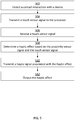
- Figure 5 is a flow chart of steps for performing another method for providing proximity-based haptic feedback.
- the steps in Figure 5 may be implemented in program code that is executable by a processor, for example, the processor in a general purpose computer, a mobile device, or a server. In some embodiments, these steps may be implemented by a group of processors. In some embodiments, one or more steps shown in Figure 5 may be omitted or performed in a different order. Similarly, in some embodiments, additional steps not shown in Figure 5 may also be performed. The steps below are described with reference to components described above with regard to the devices shown in Figure 1 .
- the method 500 begins at step 502 when the touch sensor 108 of the computing device 101 detects a user's finger contacting a touch-sensitive surface 116.
- the touch sensor 108 may be a capacitance sensor that senses a change in capacitance as the user's finger touches the sensor 108.
- the touch sensor 108 may be integrated with the proximity sensor 132 and/or with the haptic output device 118.
- the touch sensor 108 next transmits a touch sensor signal to the processor 102.
- the method continues at step 504, where the touch sensor 108 generates a signal and transmits the signal to the processor 102.
- the processor 102 receives the touch sensor signal.
- the method 500 continues at step 508 when the processor 102 determines a haptic effect based at least in part on the touch sensor signal and on the proximity signal.
- the processor 102 may be configured to output a particular haptic effect associated with a particular control on a user interface element displayed on the touch sensitive surface 116. Such a haptic effect may further be modified or combined with another haptic effect based on the proximity sensor signal.
- the haptic effect can include one or more haptic effects.
- the haptic effect can include a haptic effect meant to confirm "pushing" on a virtual button.
- the method continues at step 510 when the processor 102 transmits a haptic signal associated with the haptic effect to the haptic output device 118.
- the processor 102 may transmit one or more haptic signals to the haptic output device 118.
- the haptic effect generation module 128 causes the processor 102 to generate and transmit the haptic signal to the haptic output device 118.
- the method 500 continues at step 512 when haptic output device 118 outputs the haptic effect based on the availability and location of the display device 136.
- the haptic effect comprises a vibration, a surface deformation, a squeeze, a poke, and/or a puff of a solid, liquid, gas, or plasma.
- the haptic effect may comprise a change to the coefficient of friction of the device.
- the haptic effect may comprise a vibration.
- Embodiments of the present disclosure provide advantages in a variety of implementations. For example, as described above, an embodiment implemented in conjunction with a user interface in an automobile or any vehicle or equipment in which the user may wish to interact with a user interface while maintaining focus outside the vehicle provides the benefit of allowing the operator to focus on the road or any outside element while interacting with the user interface. For instance, a heavy equipment operator could continue to watch an implement on the equipment while simultaneously interacting with a user interface on the vehicle. Embodiments of the present disclosure may also be advantageous in small screen devices. For example, a watch incorporating proximity-based haptic feedback may allow the user to more accurately choose controls on the small screen.
- Such an implementation may allow a user to navigate the user interface without looking at the screen. For instance, if a user were running and holding a phone in the user's hand, the user may be able to navigate the user interface without looking at the screen.
- Another similar embodiment would include a game controller. With such an embodiment, the user is able to focus on the screen while simultaneously interacting with a user interface, without the need to look extensively at the user interface display on the game controller.
- configurations may be described as a process that is depicted as a flow diagram or block diagram. Although each may describe the operations as a sequential process, many of the operations can be performed in parallel or concurrently. In addition, the order of the operations may be rearranged. A process may have additional steps not included in the figure.
- examples of the methods may be implemented by hardware, software, firmware, middleware, microcode, hardware description languages, or any combination thereof. When implemented in software, firmware, middleware, or microcode, the program code or code segments to perform the necessary tasks may be stored in a non-transitory computer-readable medium such as a storage medium. Processors may perform the described tasks.
- a computer may comprise a processor or processors.
- the processor comprises or has access to a computer-readable medium, such as a random access memory (RAM) coupled to the processor.
- RAM random access memory
- the processor executes computer-executable program instructions stored in memory, such as executing one or more computer programs including a sensor sampling routine, selection routines, and other routines to perform the methods described above.
- Such processors may comprise a microprocessor, a digital signal processor (DSP), an application-specific integrated circuit (ASIC), field programmable gate arrays (FPGAs), and state machines.
- Such processors may further comprise programmable electronic devices such as PLCs, programmable interrupt controllers (PICs), programmable logic devices (PLDs), programmable read-only memories (PROMs), electronically programmable read-only memories (EPROMs or EEPROMs), or other similar devices.
- Such processors may comprise, or may be in communication with, media, for example tangible computer-readable media, that may store instructions that, when executed by the processor, can cause the processor to perform the steps described herein as carried out, or assisted, by a processor.
- Embodiments of computer-readable media may comprise, but are not limited to, all electronic, optical, magnetic, or other storage devices capable of providing a processor, such as the processor in a web server, with computer-readable instructions.
- Other examples of media comprise, but are not limited to, a floppy disk, CD-ROM, magnetic disk, memory chip, ROM, RAM, ASIC, configured processor, all optical media, all magnetic tape or other magnetic media, or any other medium from which a computer processor can read.
- various other devices may comprise computer-readable media, such as a router, private or public network, or other transmission device.
- the processor, and the processing, described may be in one or more structures, and may be dispersed through one or more structures.
- the processor may comprise code for carrying out one or more of the methods (or parts of methods) described herein.
Landscapes
- Engineering & Computer Science (AREA)
- General Engineering & Computer Science (AREA)
- Theoretical Computer Science (AREA)
- Human Computer Interaction (AREA)
- Physics & Mathematics (AREA)
- General Physics & Mathematics (AREA)
- Mechanical Engineering (AREA)
- User Interface Of Digital Computer (AREA)
- Telephone Function (AREA)
Applications Claiming Priority (1)
| Application Number | Priority Date | Filing Date | Title |
|---|---|---|---|
| US15/377,096 US11175738B2 (en) | 2016-12-13 | 2016-12-13 | Systems and methods for proximity-based haptic feedback |
Publications (1)
| Publication Number | Publication Date |
|---|---|
| EP3336680A1 true EP3336680A1 (fr) | 2018-06-20 |
Family
ID=60661800
Family Applications (1)
| Application Number | Title | Priority Date | Filing Date |
|---|---|---|---|
| EP17206294.5A Ceased EP3336680A1 (fr) | 2016-12-13 | 2017-12-08 | Systèmes et procédés de rétroaction haptique à base de proximité |
Country Status (5)
| Country | Link |
|---|---|
| US (1) | US11175738B2 (fr) |
| EP (1) | EP3336680A1 (fr) |
| JP (1) | JP2018116691A (fr) |
| KR (1) | KR20180068303A (fr) |
| CN (1) | CN108279770A (fr) |
Families Citing this family (9)
| Publication number | Priority date | Publication date | Assignee | Title |
|---|---|---|---|---|
| US20180074607A1 (en) * | 2016-09-11 | 2018-03-15 | Ace Zhang | Portable virtual-reality interactive system |
| CN109323782B (zh) * | 2018-10-26 | 2023-09-08 | 河北工业大学 | 一种非阵列式超级电容式触觉传感器及应用 |
| CN109799904A (zh) * | 2018-12-27 | 2019-05-24 | 西安交通大学 | 一种基于pvc凝胶驱动的触觉反馈结构及其制作方法和应用 |
| WO2021186665A1 (fr) * | 2020-03-19 | 2021-09-23 | 日本電信電話株式会社 | Dispositif de présentation de perception tactile, système de présentation de mouvement propre, procédé de présentation de perception tactile et programme |
| KR102378616B1 (ko) | 2020-07-31 | 2022-03-24 | 주식회사 다모아텍 | 모션 피드백 인터페이스를 위한 다중 영역 모션 센서 및 그 동작 방법 |
| KR102357722B1 (ko) | 2020-12-29 | 2022-02-08 | 주식회사 다모아텍 | 채널 스페이싱에 의하여 채널 간 간섭을 저감한 모션 피드백 인터페이스를 위한 근접 감지 센서 및 그 동작 방법 |
| KR102357724B1 (ko) | 2020-12-29 | 2022-02-08 | 주식회사 다모아텍 | 단일 채널 센싱에 기반하여 제스쳐, 터치, 및 터치 포스를 감지할 수 있는 하이브리드 제스쳐 센서 및 그 동작 방법 |
| CN115756215B (zh) * | 2023-01-04 | 2025-07-29 | 汕头超声显示器技术有限公司 | 一种表面可变屏体 |
| US12494115B2 (en) | 2023-08-15 | 2025-12-09 | Valve Corporation | Broadband haptic system |
Citations (5)
| Publication number | Priority date | Publication date | Assignee | Title |
|---|---|---|---|---|
| EP2141580A2 (fr) * | 2008-06-30 | 2010-01-06 | LG Electronics Inc. | Distinction de signaux d'entrée détectés par un terminal mobile |
| EP2209060A2 (fr) * | 2006-10-04 | 2010-07-21 | Immersion Corporation | Effets haptiques avec détection de proximité |
| US20130249859A1 (en) * | 2012-03-26 | 2013-09-26 | Electronics And Telecommunications Research Institute | Haptic actuating touch screen |
| EP2887187A1 (fr) * | 2013-12-13 | 2015-06-24 | LG Display Co., Ltd. | Écran tactile de type haptique monolithique, son procédé de fabrication et dispositif d'affichage comprenant celui-ci |
| EP2933709A2 (fr) * | 2014-04-15 | 2015-10-21 | Samsung Electronics Co., Ltd | Procédé de gestion d'informations haptiques et dispositif électronique permettant de mettre en oeuvre celui-ci |
Family Cites Families (31)
| Publication number | Priority date | Publication date | Assignee | Title |
|---|---|---|---|---|
| US5311175A (en) | 1990-11-01 | 1994-05-10 | Herbert Waldman | Method and apparatus for pre-identification of keys and switches |
| EP0556999B1 (fr) | 1992-02-18 | 1998-05-27 | NCR International, Inc. | Appareil de traitement de données doté d'une réaction (feedback) aux entrées de l'utilisateur |
| US6252583B1 (en) | 1997-11-14 | 2001-06-26 | Immersion Corporation | Memory and force output management for a force feedback system |
| JP3888099B2 (ja) * | 2001-08-17 | 2007-02-28 | 富士ゼロックス株式会社 | タッチパネル装置 |
| KR100980902B1 (ko) | 2002-05-16 | 2010-09-07 | 소니 주식회사 | 입력 방법 및 입력 장치 |
| JP4091871B2 (ja) | 2003-04-16 | 2008-05-28 | アルパイン株式会社 | データ処理装置 |
| TWI267021B (en) | 2005-06-06 | 2006-11-21 | Elan Microelectronics Corp | Touch panel supporting dual-surface operation |
| TWM290591U (en) | 2005-09-23 | 2006-05-11 | Elan Microelectronics Corp | Pushbutton touch panel module |
| JP2008123431A (ja) | 2006-11-15 | 2008-05-29 | Canon Inc | 接触提示装置及び方法 |
| US20080238886A1 (en) | 2007-03-29 | 2008-10-02 | Sony Ericsson Mobile Communications Ab | Method for providing tactile feedback for touch-based input device |
| JP2009134473A (ja) | 2007-11-29 | 2009-06-18 | Sony Corp | 押圧検知センサ、入力装置及び電子機器 |
| KR101474963B1 (ko) * | 2008-07-01 | 2014-12-19 | 엘지전자 주식회사 | 휴대 단말기 및 그 제어방법 |
| US10289199B2 (en) | 2008-09-29 | 2019-05-14 | Apple Inc. | Haptic feedback system |
| WO2010064387A1 (fr) | 2008-12-04 | 2010-06-10 | 三菱電機株式会社 | Dispositif de saisie sur écran |
| WO2010091276A2 (fr) | 2009-02-06 | 2010-08-12 | Pressure Profile Systems, Inc. | Capteur tactile capacitif de proximité |
| JP5088383B2 (ja) | 2010-01-25 | 2012-12-05 | 横河電機株式会社 | スイッチ |
| JP5847407B2 (ja) | 2010-03-16 | 2016-01-20 | イマージョン コーポレーションImmersion Corporation | プレタッチ及びトゥルータッチのためのシステム及び方法 |
| US20140312737A1 (en) * | 2011-03-07 | 2014-10-23 | Bayer Intellectual Property Gmbh | Layer composite comprising electroactive layers |
| US9235265B2 (en) * | 2012-05-17 | 2016-01-12 | Sharp Kabushiki Kaisha | Touch-screen device including tactile feedback actuator |
| US8736551B2 (en) | 2012-07-12 | 2014-05-27 | Atmel Corporation | Touch-sensor-controller sensor hub |
| KR20160019468A (ko) | 2013-06-11 | 2016-02-19 | 임머숀 코퍼레이션 | 압력 기반 햅틱 효과들을 위한 시스템들 및 방법들 |
| JP6086350B2 (ja) * | 2013-08-09 | 2017-03-01 | 株式会社デンソー | タッチパネル式入力装置、およびタッチパネル式入力方法 |
| EP3049900B1 (fr) | 2013-09-27 | 2020-11-18 | Sensel, Inc. | Systèmes de détecteur à capteur tactile et procédé |
| US9639158B2 (en) * | 2013-11-26 | 2017-05-02 | Immersion Corporation | Systems and methods for generating friction and vibrotactile effects |
| WO2015193804A2 (fr) * | 2014-06-16 | 2015-12-23 | Basf Se | Détecteur permettant de déterminer la position d'au moins un objet |
| DE202015006142U1 (de) | 2014-09-02 | 2015-12-09 | Apple Inc. | Elektronische Touch-Kommunikation |
| KR20160031334A (ko) * | 2014-09-12 | 2016-03-22 | 엘지전자 주식회사 | 이동단말기 및 그 제어방법 |
| AU2016100399B4 (en) | 2015-04-17 | 2017-02-02 | Apple Inc. | Contracting and elongating materials for providing input and output for an electronic device |
| US10664053B2 (en) * | 2015-09-30 | 2020-05-26 | Apple Inc. | Multi-transducer tactile user interface for electronic devices |
| WO2017165894A1 (fr) * | 2016-03-25 | 2017-09-28 | Sensel Inc. | Système et procédé de détection et de caractérisation d'entrées d'effort sur une surface |
| JP6728386B2 (ja) * | 2016-03-31 | 2020-07-22 | センセル インコーポレイテッドSensel,Inc. | 人間コンピュータインタフェースシステム |
-
2016
- 2016-12-13 US US15/377,096 patent/US11175738B2/en not_active Expired - Fee Related
-
2017
- 2017-12-08 EP EP17206294.5A patent/EP3336680A1/fr not_active Ceased
- 2017-12-11 JP JP2017236687A patent/JP2018116691A/ja active Pending
- 2017-12-12 CN CN201711322141.5A patent/CN108279770A/zh active Pending
- 2017-12-12 KR KR1020170170131A patent/KR20180068303A/ko not_active Ceased
Patent Citations (6)
| Publication number | Priority date | Publication date | Assignee | Title |
|---|---|---|---|---|
| EP2209060A2 (fr) * | 2006-10-04 | 2010-07-21 | Immersion Corporation | Effets haptiques avec détection de proximité |
| EP2141580A2 (fr) * | 2008-06-30 | 2010-01-06 | LG Electronics Inc. | Distinction de signaux d'entrée détectés par un terminal mobile |
| EP2141580B1 (fr) * | 2008-06-30 | 2018-05-16 | LG Electronics Inc. | Distinction de signaux d'entrée détectés par un terminal mobile |
| US20130249859A1 (en) * | 2012-03-26 | 2013-09-26 | Electronics And Telecommunications Research Institute | Haptic actuating touch screen |
| EP2887187A1 (fr) * | 2013-12-13 | 2015-06-24 | LG Display Co., Ltd. | Écran tactile de type haptique monolithique, son procédé de fabrication et dispositif d'affichage comprenant celui-ci |
| EP2933709A2 (fr) * | 2014-04-15 | 2015-10-21 | Samsung Electronics Co., Ltd | Procédé de gestion d'informations haptiques et dispositif électronique permettant de mettre en oeuvre celui-ci |
Also Published As
| Publication number | Publication date |
|---|---|
| KR20180068303A (ko) | 2018-06-21 |
| US20180164886A1 (en) | 2018-06-14 |
| JP2018116691A (ja) | 2018-07-26 |
| US11175738B2 (en) | 2021-11-16 |
| CN108279770A (zh) | 2018-07-13 |
Similar Documents
| Publication | Publication Date | Title |
|---|---|---|
| US11175738B2 (en) | Systems and methods for proximity-based haptic feedback | |
| US10319200B2 (en) | Systems and methods for haptic surface elements | |
| US10564729B2 (en) | Haptic feedback using a field of view | |
| US10551964B2 (en) | Systems and methods for manipulating a graphical user interface through gestures in real space and providing associated haptic effects | |
| US9836150B2 (en) | System and method for feedforward and feedback with haptic effects | |
| US10013063B2 (en) | Systems and methods for determining haptic effects for multi-touch input | |
| EP2796964B1 (fr) | Système et procédé pour surface déformable activée de manière haptique | |
| US9851805B2 (en) | Systems and methods for haptically-enabled holders | |
| JP2016219008A (ja) | ユーザ・インターフェースと対話するユーザに触覚効果を与えるためのシステムおよび方法 | |
| US20200192480A1 (en) | Systems and methods for providing haptic effects based on a user's motion or environment | |
| US20190265794A1 (en) | Haptic feedback for opportunistic displays |
Legal Events
| Date | Code | Title | Description |
|---|---|---|---|
| PUAI | Public reference made under article 153(3) epc to a published international application that has entered the european phase |
Free format text: ORIGINAL CODE: 0009012 |
|
| STAA | Information on the status of an ep patent application or granted ep patent |
Free format text: STATUS: THE APPLICATION HAS BEEN PUBLISHED |
|
| AK | Designated contracting states |
Kind code of ref document: A1 Designated state(s): AL AT BE BG CH CY CZ DE DK EE ES FI FR GB GR HR HU IE IS IT LI LT LU LV MC MK MT NL NO PL PT RO RS SE SI SK SM TR |
|
| AX | Request for extension of the european patent |
Extension state: BA ME |
|
| STAA | Information on the status of an ep patent application or granted ep patent |
Free format text: STATUS: REQUEST FOR EXAMINATION WAS MADE |
|
| 17P | Request for examination filed |
Effective date: 20181220 |
|
| RBV | Designated contracting states (corrected) |
Designated state(s): AL AT BE BG CH CY CZ DE DK EE ES FI FR GB GR HR HU IE IS IT LI LT LU LV MC MK MT NL NO PL PT RO RS SE SI SK SM TR |
|
| STAA | Information on the status of an ep patent application or granted ep patent |
Free format text: STATUS: EXAMINATION IS IN PROGRESS |
|
| 17Q | First examination report despatched |
Effective date: 20210203 |
|
| STAA | Information on the status of an ep patent application or granted ep patent |
Free format text: STATUS: THE APPLICATION HAS BEEN REFUSED |
|
| 18R | Application refused |
Effective date: 20221110 |