EP3336710B1 - I²c-brückenvorrichtung - Google Patents
I²c-brückenvorrichtung Download PDFInfo
- Publication number
- EP3336710B1 EP3336710B1 EP16204429.1A EP16204429A EP3336710B1 EP 3336710 B1 EP3336710 B1 EP 3336710B1 EP 16204429 A EP16204429 A EP 16204429A EP 3336710 B1 EP3336710 B1 EP 3336710B1
- Authority
- EP
- European Patent Office
- Prior art keywords
- module
- child
- bus
- parent
- bridge
- Prior art date
- Legal status (The legal status is an assumption and is not a legal conclusion. Google has not performed a legal analysis and makes no representation as to the accuracy of the status listed.)
- Active
Links
Images


Classifications
-
- G—PHYSICS
- G06—COMPUTING OR CALCULATING; COUNTING
- G06F—ELECTRIC DIGITAL DATA PROCESSING
- G06F13/00—Interconnection of, or transfer of information or other signals between, memories, input/output devices or central processing units
- G06F13/38—Information transfer, e.g. on bus
- G06F13/40—Bus structure
- G06F13/4004—Coupling between buses
- G06F13/4027—Coupling between buses using bus bridges
- G06F13/4045—Coupling between buses using bus bridges where the bus bridge performs an extender function
-
- G—PHYSICS
- G06—COMPUTING OR CALCULATING; COUNTING
- G06F—ELECTRIC DIGITAL DATA PROCESSING
- G06F13/00—Interconnection of, or transfer of information or other signals between, memories, input/output devices or central processing units
- G06F13/38—Information transfer, e.g. on bus
- G06F13/40—Bus structure
- G06F13/4004—Coupling between buses
- G06F13/4027—Coupling between buses using bus bridges
- G06F13/4031—Coupling between buses using bus bridges with arbitration
-
- G—PHYSICS
- G06—COMPUTING OR CALCULATING; COUNTING
- G06F—ELECTRIC DIGITAL DATA PROCESSING
- G06F13/00—Interconnection of, or transfer of information or other signals between, memories, input/output devices or central processing units
- G06F13/38—Information transfer, e.g. on bus
- G06F13/42—Bus transfer protocol, e.g. handshake; Synchronisation
- G06F13/4282—Bus transfer protocol, e.g. handshake; Synchronisation on a serial bus, e.g. I2C bus, SPI bus
- G06F13/4291—Bus transfer protocol, e.g. handshake; Synchronisation on a serial bus, e.g. I2C bus, SPI bus using a clocked protocol
-
- H—ELECTRICITY
- H04—ELECTRIC COMMUNICATION TECHNIQUE
- H04L—TRANSMISSION OF DIGITAL INFORMATION, e.g. TELEGRAPHIC COMMUNICATION
- H04L5/00—Arrangements affording multiple use of the transmission path
- H04L5/14—Two-way operation using the same type of signal, i.e. duplex
-
- G—PHYSICS
- G06—COMPUTING OR CALCULATING; COUNTING
- G06F—ELECTRIC DIGITAL DATA PROCESSING
- G06F2213/00—Indexing scheme relating to interconnection of, or transfer of information or other signals between, memories, input/output devices or central processing units
- G06F2213/0016—Inter-integrated circuit (I2C)
Definitions
- the present invention is generally related to the field of communication based on the I 2 C bus. More in particular, it relates to a bridge device for use in connection with such a bus.
- I 2 C inter-IC control
- I 2 C devices are very popular among designers of electronic systems because such devices offer an inexpensive way to provide distributed monitoring or control of a piece of equipment using a simple two wire serial communication bus.
- I 2 C devices are available to monitor voltage, temperature and other physical quantities, and provide non-volatile memory, parallel IO ports and a large variety of other specialized functions. Such devices are widely used in many types of electronic equipment from consumer electronics to computer systems.
- I 2 C bus Devices on an I 2 C bus are either masters or slaves.
- the master is always the device that drives the clock line.
- the slaves respond to the master.
- a slave device cannot initiate a transfer over the I 2 C bus, only a master can do that.
- both master and slave can transfer data over the I 2 C bus, but that transfer is always controlled by the master.
- SCL and SDA Communication over an I 2 C bus occurs over two wires, called SCL and SDA.
- the clock line SCL is used to synchronize all data transfers over the I 2 C bus.
- SDA is the data line.
- the SCL and SDA lines are connected to all devices on the I 2 C bus. There needs to be a third wire which is just the ground or 0 volt. There may also be a power supply wire to distribute power to the devices.
- Both SCL and SDA lines are "open drain" drivers, meaning that the chip can drive its output low, but it cannot drive it high. For the line to be able to go high pull-up resistors must be provided to the power supply wire. There should be a resistor from the SCL line to the power supply line and another from the SDA line to the power supply line. Only one set of pull-up resistors is needed for the whole I 2 C bus, not for each device.
- I 2 C protocol As described e.g. in I 2 C bus Specification, Version 6.0, 4 April 2014, I 2 C protocol is often used. There are, however, a number of problems and limitations related to the use of the I 2 C protocol.
- the I 2 C protocol does not specify voltage levels. Usually the I/O voltage at which a device operates, specifies the voltage levels that translate to a logical HIGH or LOW level. For example, in case a master uses 3.3V, it becomes impossible to connect a device which only expects 1.8V. In low-power designs though, devices are often powered with a voltage as low as possible in order to reduce power consumption. So in case not all devices share the same minimal voltage level, in order to achieve an optimal power consumption, they are likely to become I 2 C incompatible.
- the I 2 C protocol clock SCL is specified to run at varying maximum frequencies, e.g. 100kHz, 400kHz, 1MHz and 3.4MHz.
- maximum frequencies e.g. 100kHz, 400kHz, 1MHz and 3.4MHz.
- the bus must operate at the lowest supported speed of all devices, in order for all of them to interpret the communication correctly. Any device must indeed be able to correctly interpret all communication on the bus it is connected to, for it to know it should leave the bus untouched or respond.
- I 2 C is intended mostly as a low-speed protocol, it is often desired to use a communication speed as high as possible for longer data transfers, e.g. for programming a memory device.
- the controller and peripheral devices are not always physically connectable to the same I 2 C bus.
- a high speed serial link can be used to allow communication between the PCBs.
- Patent document US6874052 discloses an I 2 C bridge device which implements a communication protocol layered on top of a standard I 2 C protocol.
- the layered protocol used by the bridge device is named "Layered I 2 C Protocol" (LIP).
- LIP Layered I 2 C Protocol
- the LIP bridge device provides I 2 C address space extension, data integrity checking and fault detection and isolation when inserted between an I 2 C bus master and its intended target I 2 C device.
- Each LIP bridge device has at least two attached I 2 C busses-a parent bus and a child bus.
- the LIP bridge operates as a slave on its parent bus, and a master of its child bus.
- the Layered I 2 C protocol is specified to operate on a bus between one or more bus masters and the parent bus of one or more LIP bridge devices.
- the child bus is used for attaching multiple I 2 C devices and/or one or more LIP bridge devices.
- LIP custom protocol
- I 2 C sequences become in fact asynchronous: where in regular I 2 C, receiving an ACK from the slave device is a means for the master to know the data was received, in the LIP approach, data from the master is acknowledged immediately by the bridge, before the data from the master is sent to the slave.
- the invention relates to a bridge device operable between a master device and a slave device of a communication system, said master device and said slave device arranged for communicating with each other via a parent I 2 C bus and a child I 2 C bus and using the I 2 C protocol.
- the bridge device comprises
- the proposed solution indeed allows for overcoming the above-mentioned problems and achieving more reliable communication. Due to the fact that each module can hold the communication towards the I 2 C bus it is connected to, while waiting for a notification by the other side that the communication can continue, the communication system is never left in a falsely assumed correct state.
- the main benefit of the proposed bridge device lies in its full transparency.
- the internal bridge interfaces of the parent module and the child module are connected via a bidirectional communication link.
- the bidirectional communication link then advantageously comprises in each direction a First-In-First-Out buffer.
- the bidirectional communication link also contains an off-board link.
- the child module is arranged for connecting a plurality of child I 2 C busses.
- the child module then comprises an address-to-I 2 C child bus index table, said table comprising a list of the various I 2 C busses that are available.
- the message is caused by either an I 2 C start condition followed by an I 2 C device address, an I 2 C stop condition, an I 2 C acknowledge, an I 2 C not-acknowledge or an I 2 C byte.
- the bridge device of the invention is implemented using a field-programmable gate array, a complex programmable logic device or an application specific integrated circuit.
- the parent module comprises a digital input pin on which an external pulse can trigger the transmission of an error message to the child module and wherein the child module comprises a digital output pin to generate a pulse in response to receipt of the error message.
- the invention in another aspect relates to a communication system comprising at least one master device, at least one slave device and a bridge device as in any of the previous claims, wherein said at least one master device and said at least one slave device are arranged for communicating with each other via a parent I 2 C bus and a child I 2 C bus and using the I 2 C protocol.
- the present invention proposes a digital bridge device for use in a communication scheme which is fully transparent to all I 2 C host and slave devices.
- the transparent byte-level bridge joins at least two I 2 C buses, with at least one parent bus where an I 2 C master lives and at least one child bus where an I 2 C slave lives.
- the bridge operates as an I 2 C slave on the parent bus and as an I 2 C master on the child bus.
- Bridge messages are used to transfer I 2 C events and data internally between the bridge ends.
- Clock stretching is used to hold an I 2 C bus for which the bridge is awaiting a response, as detailed below.
- Neither any master nor slave device has to be adjusted to work with the bridge.
- Neither any master nor slave device is able to detect presence of the bridge device.
- the bridge buffers a single I 2 C byte (if preceded by an I 2 C start condition, this is the I 2 C slave device address) from the master and holds the communication on the master side by stretching SCLp (i.e. the clock line at the parent side) until the bridge has received a response from the slave side.
- SCLp i.e. the clock line at the parent side
- SCLc i.e. the clock line at the child side
- the bridge can operate as a router: a parent module linked with multiple child modules can choose to which child module it will route the I 2 C sequence. Similarly, a child module with multiple child I 2 C buses can choose to which child I 2 C bus to route the I 2 C sequence.
- the bridge device of this invention is fully transparent to both master device and slave device. Throughout the whole communication, neither the master or slave side needs to obey other than standard I 2 C protocol specifications. The proposed bridge does not have as much overhead as in US6874052 and is not affected by the complication that an acknowledgement is sent to the master before one knows there has been an acknowledgement at the slave side.
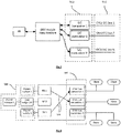
- a high-level scheme of an embodiment of the bridge is shown in Fig.1 .
- a parent I 2 C bus 50 is connected to the bridge via an I 2 C transmitter/receiver device (transceiver) 58 of a parent module 54 and a child I 2 C bus 52 is connected via an I 2 C transceiver 60 of a child module 56.
- the modules form two logical parts of the bridge device.
- Each I 2 C transceiver is in this embodiment connected to a corresponding state machine.
- the state machines of the two modules are connected via Internal Bridge Interfaces (IBIs) (66,68), with a bidirectional communication link 64 in between.
- IBIs and link in between thus connect the parent and the child side of the bridge.
- the implementation of this link can take different forms, e.g.
- the bridge thus comprises a parent module with a parent I 2 C transceiver to connect a parent I 2 C bus, a child module with a child I 2 C transceiver to connect a child I 2 C bus and is arranged for exchanging messages between the modules using internal bridge interfaces.
- the state machines of the two modules of the bridge present outgoing messages to the link using an outgoing Internal Bridge Interface (110, 162). This comprises an outgoing Internal Bridge Message IBIMo (114, 166) and an incoming ACK flag ACKi (116, 168).
- the state machines accept incoming messages from the link via an incoming Internal Bridge Interface (112, 164). This comprises an incoming Internal Bridge Message IBIMi (118, 170), and an outgoing ACK flag ACKo (120, 172).
- the combination of IBIMo, ACKi, IBIMi and ACKo is called an IBI.
- the link listens for an incoming Internal Bridge Interface Message on the IBIMi line 200 from a module and when the link has the capacity to accept the message, it asserts the ACKo flag 202 for one clock cycle to notify the module it can present the next message.
- the other module listens for an outgoing Internal Bridge Message on the IBIMo line 204, and when the latter module is ready to accept the message, the module asserts the ACK flag 206 for one clock cycle to notify the link it can present the next message. Since link-to-module and module-to-link are identical paths, the modules can be connected immediately, i.e. connecting one module's IBIMo to the other module's IBIMi and vice versa, as well connecting one module's ACKo to the other module's ACK.
- the link can take the form of two opposite direction FIFO buffers with an IBI-to-FIFO 250 and FIFO-to-IBI 252 interface on each end of each FIFO 254, as illustrated in Fig.5 .
- the link can also contain an off-board link, eventually allowing and I 2 C master on board A to communicate with an I 2 C slave on board B.
- the I 2 C transceiver of the parent module can be considered a virtual I 2 C slave, representing all I 2 C slave devices on the other side of the bridge device.
- the I 2 C transceiver of the child module can be considered a virtual I 2 C master, representing all I 2 C masters which have access to the child module.
- IBI Internal Bridge Interface
- Such an Internal Bridge Interface message 16 comprises an I 2 C event field 400 and an optional data byte field 402 (see Fig.6 ).
- IBI Internal Bridge Interface
- Table 1 seven events exist: TABLE 1 Event Data byte Description Direction NOP ignored Indicates no message is available on the IBI.
- the data byte is the byte the master sent out immediately following the start condition. This typically represents the I 2 C slave device address and a bit indicating if a read or write operation will follow.
- Every I 2 C transaction begins with a START condition and an address byte, which translates to a START message with that same address byte.
- a child module can be modified to have multiple I 2 C transceivers 500, providing access to different child I 2 C buses 502 as illustrated in Fig.7 .
- IBIM ⁇ START address ⁇ reaches the child module, it can then choose which child I 2 C bus to forward this I 2 C transaction to, based on the address.
- the child module then continues to use the same I 2 C child bus for forwarding messages to until another START message arrives. At that point, the child module again chooses which child I 2 C bus is used based on the address byte in the last received IBIM.
- I 2 C slave devices with the same address X exist in a system, they can be placed on two separate child buses connected to the child module, as described above.
- the child module can then translate a first address A received from a master module to that I 2 C slave address X and first child bus and a second address B received from a master module to the that same I 2 C slave address X and second child bus.
- a and B must be different, but A or B can be equal to X (see first two lines in Table 8).
- an I 2 C transaction is delimited by a START and STOP condition, which translates to a START and STOP message in terms of IBI, one can delimit a time slot in which a parent module controls a child module.
- This can be used in a so-called module multiplexer (illustrated in Fig.8 ), which connects a multitude of parent modules 550 to a multitude of child I 2 C buses 552.
- module multiplexer illustrated in Fig.8
- these accesses can overlap in time, as suggested by the lines 554.
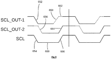
- Fig.9 shows a timing diagram illustrating clock-stretching.
- the timing diagram shows three representative waveforms: SCL_OUT-1 representing the driver output of the clock line of a first device; SCL_OUT-2 representing the driver output of the clock line of a second device; and SCL representing the actual signal that appears on the SCL clock line of an I 2 C-bus.
- the SCL signal represents the actual logic value on the line after the Wired-AND function-this is also the value read by the input buffer of all devices. Where either of the output buffer values differ from the resolved. SCL value, this is represented by a dotted line.
- the sequence in the timing diagram of Fig.9 is as follows:
- Example A an I 2 C write sequence
- an I 2 C start condition occurs.
- an I 2 C start condition has occurred followed by 8 bits incorporating the device address (here 0x1C, or 0x38 if the R/W bit is considered as an address bit) as well as whether the master wants to perform a read or write operation (here write, since SDA is '0' at the 8th rising SCL of the parent I 2 C bus 606).
- the master device which initiated the I 2 C operation on the parent bus now checks for an acknowledgement from the slave device.
- an acknowledgement is represented by the slave holding SDA low during the next rising edge on SCL.
- the parent module cannot yet give an appropriate "acknowledge” (ACK) or “not acknowledge” (NACK).
- ACK acknowledgeledge
- NACK not acknowledge
- the child module has received the IBIM message and in turn produces a START condition on the child bus, followed by the device address .
- the child module releases SDA to read its state on the 9th rising edge 614 of SCLc of the child I 2 C bus. In this case SDAc is low, so the child module presents IBIM ⁇ ACK ⁇ (452) to the link. If it were high, it would present IBIM ⁇ NACK ⁇ . After receiving the ACK on the child I 2 C bus, the child module keeps SCLp low to hold the child I 2 C bus while the child module awaits the next event from the link.
- the parent module has received IBIM ⁇ ACK ⁇ from the link and translates the received message to the parent bus by pulling SDAp low. It then releases SCLp 620 of the parent bus, so the master can continue the I 2 C sequence. Once the master has received the ACK signal, the parent module continues to receive the next byte.
- the parent module once again makes the master wait by stretching the clock as it presents IBIM ⁇ DATA, 0xB6 ⁇ (454) to the link.
- the child module has received the IBIM ⁇ DATA, 0xB6 ⁇ . It releases SCL and continues to generate a clock signal on SCLc, while sending the 8 data bits onto the child bus and receives the slave's ACK/NACK at 626. This results in the child bus being held (SCLc pulled low, 628) and an IBIM ⁇ ACK/NACK ⁇ (456) presented to the link, which results in an ACK/NACK to appear on the parent bus 630.
- the master generates a STOP condition, which makes the parent module send IBIM ⁇ STOP ⁇ (458) to the link.
- the parent module then becomes idle.
- this condition is repeated on the child bus 634.
- the child module is now again in the same IDLE state as it was before the start condition.
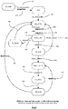
- the parent module has a state machine with 8 states (see Fig.12 ) : IDLE, RX_BYTE, AWAIT_ACK, TX_ACK, TX_NACK, AWAIT_BYTE, TX_BYTE, RX_ACK. From any state, if a start condition occurs, the state machine is forced to the RX_BYTE state 302. From any state, if a stop condition occurs, the state machine is forced to the IDLE state 304. Below is a state transition table. The state machine in the parent module is designed so that IBIMs for the link are generated upon state departure. For clarity, states where the state machine is waiting for a message from the link, have names starting with AWAIT.
- the state machine in the child module has nine states, as illustrated in Fig.13 . These states are: IDLE, TX_START, TX_BYTE, AWAIT_IBIM, RX_ACK, RX_BYTE, TX_ACK, TX_NACK, TX_STOP. Below is its state transition table. As in the parent module state machine, IBIM messages for the link are generated upon state departure. For uniformity, the state where the state machine is waiting for a message from the link, starts with AWAIT. States departure from which depends on an event on the parent I 2 C bus, have names starting with TX or RX (except for IDLE).
- both parent and child state machines are in the IDLE state. Both parent and child I 2 C bus are idle, i.e. no device on either bus is pulling SCL or SDA low.
- Example B description of an I 2 C read sequence
- lines 0 to 6 are identical to the I 2 C write sequence of the previous example, except that the DATA in the IBIM containing a START event would have an LSB equalling '1'. Steps 7 and further are shown in Table 5 and discussed below.
- the R/W bit in the device address stored in the is_reading register is checked. In this case this bit is '1', the master is reading and the child module transitions (356) to RX_BYTE.
- Example C I 2 C sequence where no ACK occurs on the child I 2 C bus
- the parent I 2 C bus locks up, since the parent I 2 C bus is being stretched while waiting for a response from the child I 2 C bus.
- This is similar to an I 2 C bus where no bridge is present. In such case, one would usually power cycle all I 2 C slave devices on the bus using a general purpose I/O pin on the I 2 C master, which is able to detect such condition.
- the parent module can be equipped with a reset input. The parent module state machine is then modified so as to generate an IBIM with an ERROR event. This is then sent to all child modules, which, equipped with a reset output, will cause a digital transition on that output. After detecting such reset condition, parent and child module will return to the IDLE state.
- a delay is inherent to the bridge. For every I 2 C event (START/STOP/ACK/NACK/DATA), the time it takes to occur, equals t parent I 2 ⁇ C bus + t link + t child I 2 ⁇ C bus where t parent I2C bus denotes the time taken on the parent I 2 C bus, t child I 2C bus the time taken on the child I 2 C bus and t link the time taken by the link to forward a message from one end to the other. For example, a DATA event takes 8 SCLp cycles on the parent bus, an internal delay of the link to propagate the IBIM, and 8 SCLc cycles on the child bus.
- the delay introduced by the link t link can be neglected.
- the address collision and voltage incompatibility problems are resolved in this invention by allowing multiple child I 2 C buses connecting on a child module and by having the child module look up to which child I 2 C bus to direct an I 2 C sequence based on the I 2 C device address and a look-up table as explained in step 4 in Example A.
- An address-to-child-bus-index look-up table may look like this TABLE 8 Device address Bus index Actual address 0x0D 0 0x0D 0x0E 1 0x0D [1] 0x14 2 0x14 0x15 2 0x15 ⁇ other> 1 ⁇ unchanged> [1] Note how the actual address is different from the device address used by the I 2 C master. This is device address translation. Notice how, when the I 2 C master device uses 0x0E for a device address, the child module translates this to 0x0D on bus 1. 0x0D is translated to 0x0D on bus 0. This allows for two I 2 C devices with the same address to be addressed by one and the same master.
- the bridge device according to this invention can be implemented with purely digital blocks, such as an FPGA, a complex programmable logic device (CPLD) or an ASIC.
- CPLD complex programmable logic device
- ASIC application specific integrated circuit
- An address-to-child-bus look-up table as used in certain embodiments can be implemented in several different ways. Some examples are :
- the invention relates to a communication system comprising at least one master device, at least one slave device and in between a bridge device as previously described.
- a communication system offers several advantages. It is sufficient to have only one central master device. Moreover, that master device is transparent and does not need to adapt, e.g. because of I 2 C slave devices that use another I/O voltage than the master, because it is impossible to bring SCL and SDA 'directly' (electrically) because of separated Printed Circuit Boards or because of distinct devices listening to the same address. Further, an 'ACK' keeps its full meaning : it is not needed to assume that an ACK will occur. This also implies that if an ACK is received, it indeed has been sent by the other side of the communication system. Further, the sender knows that the data effectively has been received.
- One exemplary embodiment of a communication system is a system where two separate PCBs exist, one master PCB with a microcontroller containing an I 2 C master, which is connected to an FPGA.
- the FPGA is configured to work as a parent module, listening on the parent I 2 C bus which is connected to the microcontroller's I 2 C master.
- the other PCB, the slave PCB is connected to the master PCB with a fast coaxial full-duplex link, which also provides power from the master to the slave PCB.
- the FPGA on the slave PCB is configured to work as slave module.
- the FPGAs on both PCBs are connected to this link, and use it to communicate with each other. This coax link can be used as bridge link between both modules, but can at the same time accommodate many other types of data streams.
Landscapes
- Engineering & Computer Science (AREA)
- Theoretical Computer Science (AREA)
- General Engineering & Computer Science (AREA)
- Physics & Mathematics (AREA)
- General Physics & Mathematics (AREA)
- Computer Hardware Design (AREA)
- Signal Processing (AREA)
- Computer Networks & Wireless Communication (AREA)
- Information Transfer Systems (AREA)
- Small-Scale Networks (AREA)
Claims (10)
- Brückengerät, betreibbar zwischen einem Master-Gerät und einem Slave-Gerät eines Kommunikationssystems, wobei das Master-Gerät und das Slave-Gerät für eine Kommunikation miteinander über einen übergeordneten I2C-Bus und einen untergeordneten I2C-Bus mit Hilfe des I2C-Protokolls angeordnet sind, wobei das Brückengerät Folgendes umfasst:- ein übergeordnetes Modul auf einer Seite des Brückengeräts, wobei das übergeordnete Modul dafür angeordnet ist, den übergeordneten I2C-Bus anzuschließen, und ein übergeordnetes I2C-Sende-/Empfangsgerät und eine Übergeordnetes-Modul-Zustandsmaschine umfasst,- ein untergeordnetes Modul auf der gegenüberliegenden Seite des Brückengeräts, wobei das untergeordnete Modul dafür angeordnet ist, den untergeordneten I2C-Bus anzuschließen, und ein untergeordnetes I2C-Sende-/Empfangsgerät und eine Untergeordnetes-Modul-Zustandsmaschine umfasst,wobei das übergeordnete Modul und das untergeordnete Modul jeweils eine interne Brückenschnittstelle umfassen, um Nachrichten zwischen dem übergeordneten Modul und dem untergeordneten Modul auszutauschen, wobei die Nachrichten durch die Übergeordnetes-Modul-Zustandsmaschine oder die Untergeordnetes-Modul-Zustandsmaschine in Reaktion auf eine Zustandsveränderung erzeugt werden, die durch ein Ereignis an ihren entsprechenden I2C-Bussen verursacht wird,
wobei das übergeordnete Modul und das untergeordnete Modul jeweils dafür angeordnet sind, ein I2C-Ereignis in eine Nachricht umzuwandeln und die Nachricht über die internen Brückenschnittstellen an das Modul auf der anderen Seite des Brückengeräts weiterzuleiten, wobei das Modul auf der anderen Seite dafür angeordnet ist, die Nachricht als ein I2C-Ereignis an den I2C-Bus auf der anderen Seite des Brückengeräts weiterzusenden, und
wobei das übergeordnete Modul und das untergeordnete Modul ferner jeweils dafür angeordnet sind, die Kommunikation zum entsprechenden I2C-Bus zu halten, indem eine Taktleitung an ihrem entsprechenden I2C-Bus verlängert wird, bis eine Nachricht, die auf einem Ereignis basiert, das an dem I2C-Bus auf der anderen Seite des Brückengeräts auftritt, und die ein Fortsetzen der Kommunikation anweist, über die internen Brückenschnittstellen von dem Modul auf der anderen Seite des Brückengeräts empfangen wird. - Brückengerät nach Anspruch 1, wobei die internen Brückenschnittstellen des übergeordneten Moduls und des untergeordneten Moduls über eine bidirektionale Kommunikationsverbindung angeschlossen sind.
- Brückengerät nach Anspruch 2, wobei die bidirektionale Kommunikationsverbindung in jeder Richtung einen First-In-First-Out-Pufferspeicher umfasst.
- Brückengerät nach Anspruch 2 oder 3, wobei die bidirektionale Kommunikationsverbindung außerdem eine Verbindung nach außen enthält.
- Brückengerät nach einem der vorhergehenden Ansprüche, wobei das untergeordnete Modul dafür angeordnet ist, mehrere untergeordnete I2C-Busse anzuschließen.
- Brückengerät nach einem der vorhergehenden Ansprüche, wobei das untergeordnete Modul eine Indextabelle für Adressen zu untergeordneten I2C-Bussen umfasst.
- Brückengerät nach einem der vorhergehenden Ansprüche, wobei die Nachricht entweder durch eine I2C-Startbedingung, gefolgt von einer I2C-Geräteadresse, einer I2C-Stoppbedingung, einer I2C-Bestätigung, einer I2C-Nichtbestätigung oder einem I2C-Byte verursacht wird.
- Brückengerät nach einem der vorhergehenden Ansprüche, umgesetzt mit Hilfe eines FPGA (Field-Programmable Gate Array), eines komplexen programmierbaren Logikgeräts oder einer anwendungsspezifischen integrierten Schaltung umgesetzt ist.
- Brückengerät nach einem der vorhergehenden Ansprüche, wobei das übergeordnete Modul einen digitalen Eingangspin umfasst, an dem ein externer Impuls das Senden einer Fehlernachricht an das untergeordnete Modul auslösen kann, und wobei das untergeordnete Modul einen digitalen Ausgangspin umfasst, um in Reaktion auf das Empfangen der Fehlernachricht einen Impuls zu erzeugen.
- Kommunikationssystem, mindestens ein Master-Gerät, mindestens ein Slave-Gerät und ein Brückengerät nach einem der vorhergehenden Ansprüche umfassend, wobei das mindestens eine Master-Gerät und das mindestens eine Slave-Gerät für die Kommunikation miteinander über einen übergeordneten I2C-Bus und einen untergeordneten I2C-Bus mit Hilfe des I2C-Protokolls angeordnet sind.
Priority Applications (3)
| Application Number | Priority Date | Filing Date | Title |
|---|---|---|---|
| EP16204429.1A EP3336710B1 (de) | 2016-12-15 | 2016-12-15 | I²c-brückenvorrichtung |
| US16/470,264 US11928066B2 (en) | 2016-12-15 | 2017-12-15 | I2C bridge device |
| PCT/EP2017/083003 WO2018109160A1 (en) | 2016-12-15 | 2017-12-15 | I2c bridge device |
Applications Claiming Priority (1)
| Application Number | Priority Date | Filing Date | Title |
|---|---|---|---|
| EP16204429.1A EP3336710B1 (de) | 2016-12-15 | 2016-12-15 | I²c-brückenvorrichtung |
Publications (2)
| Publication Number | Publication Date |
|---|---|
| EP3336710A1 EP3336710A1 (de) | 2018-06-20 |
| EP3336710B1 true EP3336710B1 (de) | 2019-10-02 |
Family
ID=57570312
Family Applications (1)
| Application Number | Title | Priority Date | Filing Date |
|---|---|---|---|
| EP16204429.1A Active EP3336710B1 (de) | 2016-12-15 | 2016-12-15 | I²c-brückenvorrichtung |
Country Status (3)
| Country | Link |
|---|---|
| US (1) | US11928066B2 (de) |
| EP (1) | EP3336710B1 (de) |
| WO (1) | WO2018109160A1 (de) |
Families Citing this family (8)
| Publication number | Priority date | Publication date | Assignee | Title |
|---|---|---|---|---|
| CN112286852B (zh) * | 2019-07-25 | 2022-08-12 | 杭州海康汽车技术有限公司 | 基于iic总线的数据通信方法和数据通信装置 |
| CN110489815B (zh) * | 2019-07-26 | 2020-09-29 | 广东高云半导体科技股份有限公司 | 基于i3c总线通信的验证方法及验证系统 |
| JP7697964B2 (ja) * | 2020-04-07 | 2025-06-24 | 深▲ジェン▼引望智能技術有限公司 | 相互集積回路プロトコルにしたがったデータ伝送方法及び伝送装置 |
| CN112131167B (zh) * | 2020-08-21 | 2022-06-21 | 山东云海国创云计算装备产业创新中心有限公司 | 一种基于lpc协议的i2c转发模块、系统及其使用方法 |
| CN112463662B (zh) * | 2020-12-16 | 2024-04-05 | 福州创实讯联信息技术有限公司 | 一种用户态控制i2c设备的方法与终端 |
| US12072821B2 (en) * | 2021-05-19 | 2024-08-27 | Sony Semiconductor Solutions Corporation | Communication device and communication system with encapsulation/de-encapsulation of data and commands |
| CN115080191B (zh) * | 2022-08-18 | 2023-01-06 | 苏州浪潮智能科技有限公司 | 一种管理i2c链路的方法、装置、设备及可读介质 |
| US12475069B2 (en) * | 2023-06-28 | 2025-11-18 | Texas Instruments Incorporated | Dynamic power gating using deterministic interconnect |
Family Cites Families (14)
| Publication number | Priority date | Publication date | Assignee | Title |
|---|---|---|---|---|
| TW362178B (en) * | 1997-01-30 | 1999-06-21 | Nxp Bv | Electronic apparatus |
| US6591322B1 (en) | 2000-08-01 | 2003-07-08 | Sun Microsystems, Inc. | Method and apparatus for connecting single master devices to a multimaster wired-and bus environment |
| US6874052B1 (en) | 2000-09-29 | 2005-03-29 | Lucent Technologies Inc. | Expansion bridge apparatus and method for an I2C bus |
| WO2002097642A1 (en) * | 2001-05-29 | 2002-12-05 | Sun Microsystems, Inc. | Method and apparatus for constructing and configuring multiple segment wired-and bus systems |
| US8433838B2 (en) * | 2010-09-17 | 2013-04-30 | International Business Machines Corporation | Remote multiplexing devices on a serial peripheral interface bus |
| EP2764443B1 (de) * | 2011-10-05 | 2022-11-30 | Analog Devices, Inc. | Zweidrahtübertragungssystem für hochgeschwindigkeitsdaten und stromverteilung |
| EP3103021B1 (de) * | 2014-02-07 | 2020-12-16 | Ascensia Diabetes Care Holdings AG | Verfahren und vorrichtung für ein mehrfachmasterbusprotokoll |
| US9904637B2 (en) * | 2014-11-26 | 2018-02-27 | Qualcomm Incorporated | In-band interrupt time stamp |
| US10102176B2 (en) * | 2015-02-06 | 2018-10-16 | Apple Inc. | Methods and apparatus for rapid switching of hardware configurations with a speed limited bus |
| US10875713B2 (en) * | 2016-03-04 | 2020-12-29 | Ubimax Gmbh | Method for technically supporting a manual order picking process |
| US20180260357A1 (en) * | 2017-03-08 | 2018-09-13 | Qualcomm Incorporated | I2c clock stretch over i3c bus |
| US20190171611A1 (en) * | 2017-12-05 | 2019-06-06 | Qualcomm Incorporated | Protocol-framed clock line driving for device communication over master-originated clock line |
| CN110659238A (zh) * | 2018-06-28 | 2020-01-07 | 鸿富锦精密电子(天津)有限公司 | 数据通信系统 |
| US20200201804A1 (en) * | 2018-12-21 | 2020-06-25 | Qualcomm Incorporated | I3c device timing adjustment to accelerate in-band interrupts |
-
2016
- 2016-12-15 EP EP16204429.1A patent/EP3336710B1/de active Active
-
2017
- 2017-12-15 WO PCT/EP2017/083003 patent/WO2018109160A1/en not_active Ceased
- 2017-12-15 US US16/470,264 patent/US11928066B2/en active Active
Non-Patent Citations (1)
| Title |
|---|
| None * |
Also Published As
| Publication number | Publication date |
|---|---|
| WO2018109160A1 (en) | 2018-06-21 |
| EP3336710A1 (de) | 2018-06-20 |
| US11928066B2 (en) | 2024-03-12 |
| US20200012611A1 (en) | 2020-01-09 |
Similar Documents
| Publication | Publication Date | Title |
|---|---|---|
| EP3336710B1 (de) | I²c-brückenvorrichtung | |
| EP0378426B1 (de) | Datenübertragung über Busadressleitungen | |
| US10169282B2 (en) | Bus serialization for devices without multi-device support | |
| CN104811273B (zh) | 一种高速单总线通信的实现方法 | |
| EP0378427B1 (de) | Hochgeschwindigkeitsdatenübertragung auf einem Rechnersystembus | |
| US5758073A (en) | Serial interface between DSP and analog front-end device | |
| US20100064083A1 (en) | Communications device without passive pullup components | |
| US5327121A (en) | Three line communications method and apparatus | |
| Trivedi et al. | Spi to i2c protocol conversion using verilog | |
| US6339806B1 (en) | Primary bus to secondary bus multiplexing for I2C and other serial buses | |
| CN102147778B (zh) | 基于半双工串行总线的数据传输系统及传输控制方法 | |
| CN101346708B (zh) | 全缓冲dimm读数据替代写确认 | |
| JP4773742B2 (ja) | 2線チップ間インターフェース | |
| US20090089538A1 (en) | Synchronous Address And Data Multiplexed Mode For SRAM | |
| WO2007124304A2 (en) | Serial communications bus with active pullup | |
| CN106168934A (zh) | 一种数据传输方法及装置 | |
| CN114925013B (zh) | 一种基于cpld的i2c信号透传方法、设备及介质 | |
| US20110219160A1 (en) | Fast two wire interface and protocol for transferring data | |
| WO2000002134A2 (en) | Improved inter-device serial bus protocol | |
| CN114911743B (zh) | Spi从机设备、spi主机设备和相关的通信方法 | |
| CN119248586B (zh) | 一种基于i2c接口ip验证的寻址模式可灵活配置的仿真验证模型 | |
| CN1282932C (zh) | 一种cpu访问小封装带电插拔光模块的方法 | |
| EP4246900B1 (de) | Verarbeitungssystem, zugehörige integrierte schaltung, vorrichtung und verfahren | |
| CN117370258B (zh) | 一种高速i2c总线的多路低速i2c扩展方法及装置 | |
| US20110007586A1 (en) | Memory interface control circuit |
Legal Events
| Date | Code | Title | Description |
|---|---|---|---|
| PUAI | Public reference made under article 153(3) epc to a published international application that has entered the european phase |
Free format text: ORIGINAL CODE: 0009012 |
|
| STAA | Information on the status of an ep patent application or granted ep patent |
Free format text: STATUS: THE APPLICATION HAS BEEN PUBLISHED |
|
| AK | Designated contracting states |
Kind code of ref document: A1 Designated state(s): AL AT BE BG CH CY CZ DE DK EE ES FI FR GB GR HR HU IE IS IT LI LT LU LV MC MK MT NL NO PL PT RO RS SE SI SK SM TR |
|
| AX | Request for extension of the european patent |
Extension state: BA ME |
|
| STAA | Information on the status of an ep patent application or granted ep patent |
Free format text: STATUS: REQUEST FOR EXAMINATION WAS MADE |
|
| 17P | Request for examination filed |
Effective date: 20181220 |
|
| RAV | Requested validation state of the european patent: fee paid |
Extension state: MD Effective date: 20181220 Extension state: MA Effective date: 20181220 |
|
| RAX | Requested extension states of the european patent have changed |
Extension state: ME Payment date: 20181220 Extension state: BA Payment date: 20181220 |
|
| RBV | Designated contracting states (corrected) |
Designated state(s): AL AT BE BG CH CY CZ DE DK EE ES FI FR GB GR HR HU IE IS IT LI LT LU LV MC MK MT NL NO PL PT RO RS SE SI SK SM TR |
|
| GRAP | Despatch of communication of intention to grant a patent |
Free format text: ORIGINAL CODE: EPIDOSNIGR1 |
|
| STAA | Information on the status of an ep patent application or granted ep patent |
Free format text: STATUS: GRANT OF PATENT IS INTENDED |
|
| INTG | Intention to grant announced |
Effective date: 20190429 |
|
| GRAS | Grant fee paid |
Free format text: ORIGINAL CODE: EPIDOSNIGR3 |
|
| GRAA | (expected) grant |
Free format text: ORIGINAL CODE: 0009210 |
|
| STAA | Information on the status of an ep patent application or granted ep patent |
Free format text: STATUS: THE PATENT HAS BEEN GRANTED |
|
| RIN1 | Information on inventor provided before grant (corrected) |
Inventor name: GROOTJANS, RIEMER Inventor name: LE CLEMENT DE SAINT-MARCQ, VIANNEY Inventor name: VAN BOURGOGNIE, JASPER Inventor name: VERSTRAETEN, PETER |
|
| AK | Designated contracting states |
Kind code of ref document: B1 Designated state(s): AL AT BE BG CH CY CZ DE DK EE ES FI FR GB GR HR HU IE IS IT LI LT LU LV MC MK MT NL NO PL PT RO RS SE SI SK SM TR |
|
| REG | Reference to a national code |
Ref country code: GB Ref legal event code: FG4D |
|
| REG | Reference to a national code |
Ref country code: CH Ref legal event code: EP Ref country code: AT Ref legal event code: REF Ref document number: 1186956 Country of ref document: AT Kind code of ref document: T Effective date: 20191015 |
|
| REG | Reference to a national code |
Ref country code: DE Ref legal event code: R096 Ref document number: 602016021598 Country of ref document: DE |
|
| REG | Reference to a national code |
Ref country code: IE Ref legal event code: FG4D |
|
| REG | Reference to a national code |
Ref country code: NL Ref legal event code: MP Effective date: 20191002 |
|
| REG | Reference to a national code |
Ref country code: LT Ref legal event code: MG4D |
|
| REG | Reference to a national code |
Ref country code: AT Ref legal event code: MK05 Ref document number: 1186956 Country of ref document: AT Kind code of ref document: T Effective date: 20191002 |
|
| PG25 | Lapsed in a contracting state [announced via postgrant information from national office to epo] |
Ref country code: LT Free format text: LAPSE BECAUSE OF FAILURE TO SUBMIT A TRANSLATION OF THE DESCRIPTION OR TO PAY THE FEE WITHIN THE PRESCRIBED TIME-LIMIT Effective date: 20191002 Ref country code: BG Free format text: LAPSE BECAUSE OF FAILURE TO SUBMIT A TRANSLATION OF THE DESCRIPTION OR TO PAY THE FEE WITHIN THE PRESCRIBED TIME-LIMIT Effective date: 20200102 Ref country code: PT Free format text: LAPSE BECAUSE OF FAILURE TO SUBMIT A TRANSLATION OF THE DESCRIPTION OR TO PAY THE FEE WITHIN THE PRESCRIBED TIME-LIMIT Effective date: 20200203 Ref country code: FI Free format text: LAPSE BECAUSE OF FAILURE TO SUBMIT A TRANSLATION OF THE DESCRIPTION OR TO PAY THE FEE WITHIN THE PRESCRIBED TIME-LIMIT Effective date: 20191002 Ref country code: LV Free format text: LAPSE BECAUSE OF FAILURE TO SUBMIT A TRANSLATION OF THE DESCRIPTION OR TO PAY THE FEE WITHIN THE PRESCRIBED TIME-LIMIT Effective date: 20191002 Ref country code: SE Free format text: LAPSE BECAUSE OF FAILURE TO SUBMIT A TRANSLATION OF THE DESCRIPTION OR TO PAY THE FEE WITHIN THE PRESCRIBED TIME-LIMIT Effective date: 20191002 Ref country code: PL Free format text: LAPSE BECAUSE OF FAILURE TO SUBMIT A TRANSLATION OF THE DESCRIPTION OR TO PAY THE FEE WITHIN THE PRESCRIBED TIME-LIMIT Effective date: 20191002 Ref country code: NO Free format text: LAPSE BECAUSE OF FAILURE TO SUBMIT A TRANSLATION OF THE DESCRIPTION OR TO PAY THE FEE WITHIN THE PRESCRIBED TIME-LIMIT Effective date: 20200102 Ref country code: ES Free format text: LAPSE BECAUSE OF FAILURE TO SUBMIT A TRANSLATION OF THE DESCRIPTION OR TO PAY THE FEE WITHIN THE PRESCRIBED TIME-LIMIT Effective date: 20191002 Ref country code: NL Free format text: LAPSE BECAUSE OF FAILURE TO SUBMIT A TRANSLATION OF THE DESCRIPTION OR TO PAY THE FEE WITHIN THE PRESCRIBED TIME-LIMIT Effective date: 20191002 Ref country code: AT Free format text: LAPSE BECAUSE OF FAILURE TO SUBMIT A TRANSLATION OF THE DESCRIPTION OR TO PAY THE FEE WITHIN THE PRESCRIBED TIME-LIMIT Effective date: 20191002 |
|
| PG25 | Lapsed in a contracting state [announced via postgrant information from national office to epo] |
Ref country code: CZ Free format text: LAPSE BECAUSE OF FAILURE TO SUBMIT A TRANSLATION OF THE DESCRIPTION OR TO PAY THE FEE WITHIN THE PRESCRIBED TIME-LIMIT Effective date: 20191002 Ref country code: IS Free format text: LAPSE BECAUSE OF FAILURE TO SUBMIT A TRANSLATION OF THE DESCRIPTION OR TO PAY THE FEE WITHIN THE PRESCRIBED TIME-LIMIT Effective date: 20200224 Ref country code: RS Free format text: LAPSE BECAUSE OF FAILURE TO SUBMIT A TRANSLATION OF THE DESCRIPTION OR TO PAY THE FEE WITHIN THE PRESCRIBED TIME-LIMIT Effective date: 20191002 Ref country code: HR Free format text: LAPSE BECAUSE OF FAILURE TO SUBMIT A TRANSLATION OF THE DESCRIPTION OR TO PAY THE FEE WITHIN THE PRESCRIBED TIME-LIMIT Effective date: 20191002 |
|
| PG25 | Lapsed in a contracting state [announced via postgrant information from national office to epo] |
Ref country code: AL Free format text: LAPSE BECAUSE OF FAILURE TO SUBMIT A TRANSLATION OF THE DESCRIPTION OR TO PAY THE FEE WITHIN THE PRESCRIBED TIME-LIMIT Effective date: 20191002 |
|
| REG | Reference to a national code |
Ref country code: DE Ref legal event code: R097 Ref document number: 602016021598 Country of ref document: DE |
|
| PG2D | Information on lapse in contracting state deleted |
Ref country code: IS |
|
| PG25 | Lapsed in a contracting state [announced via postgrant information from national office to epo] |
Ref country code: EE Free format text: LAPSE BECAUSE OF FAILURE TO SUBMIT A TRANSLATION OF THE DESCRIPTION OR TO PAY THE FEE WITHIN THE PRESCRIBED TIME-LIMIT Effective date: 20191002 Ref country code: DK Free format text: LAPSE BECAUSE OF FAILURE TO SUBMIT A TRANSLATION OF THE DESCRIPTION OR TO PAY THE FEE WITHIN THE PRESCRIBED TIME-LIMIT Effective date: 20191002 Ref country code: RO Free format text: LAPSE BECAUSE OF FAILURE TO SUBMIT A TRANSLATION OF THE DESCRIPTION OR TO PAY THE FEE WITHIN THE PRESCRIBED TIME-LIMIT Effective date: 20191002 Ref country code: IS Free format text: LAPSE BECAUSE OF FAILURE TO SUBMIT A TRANSLATION OF THE DESCRIPTION OR TO PAY THE FEE WITHIN THE PRESCRIBED TIME-LIMIT Effective date: 20200202 |
|
| REG | Reference to a national code |
Ref country code: CH Ref legal event code: PL |
|
| PLBE | No opposition filed within time limit |
Free format text: ORIGINAL CODE: 0009261 |
|
| STAA | Information on the status of an ep patent application or granted ep patent |
Free format text: STATUS: NO OPPOSITION FILED WITHIN TIME LIMIT |
|
| PG25 | Lapsed in a contracting state [announced via postgrant information from national office to epo] |
Ref country code: MC Free format text: LAPSE BECAUSE OF FAILURE TO SUBMIT A TRANSLATION OF THE DESCRIPTION OR TO PAY THE FEE WITHIN THE PRESCRIBED TIME-LIMIT Effective date: 20191002 Ref country code: IT Free format text: LAPSE BECAUSE OF FAILURE TO SUBMIT A TRANSLATION OF THE DESCRIPTION OR TO PAY THE FEE WITHIN THE PRESCRIBED TIME-LIMIT Effective date: 20191002 Ref country code: SM Free format text: LAPSE BECAUSE OF FAILURE TO SUBMIT A TRANSLATION OF THE DESCRIPTION OR TO PAY THE FEE WITHIN THE PRESCRIBED TIME-LIMIT Effective date: 20191002 Ref country code: SK Free format text: LAPSE BECAUSE OF FAILURE TO SUBMIT A TRANSLATION OF THE DESCRIPTION OR TO PAY THE FEE WITHIN THE PRESCRIBED TIME-LIMIT Effective date: 20191002 |
|
| 26N | No opposition filed |
Effective date: 20200703 |
|
| PG25 | Lapsed in a contracting state [announced via postgrant information from national office to epo] |
Ref country code: LU Free format text: LAPSE BECAUSE OF NON-PAYMENT OF DUE FEES Effective date: 20191215 Ref country code: IE Free format text: LAPSE BECAUSE OF NON-PAYMENT OF DUE FEES Effective date: 20191215 |
|
| PG25 | Lapsed in a contracting state [announced via postgrant information from national office to epo] |
Ref country code: SI Free format text: LAPSE BECAUSE OF FAILURE TO SUBMIT A TRANSLATION OF THE DESCRIPTION OR TO PAY THE FEE WITHIN THE PRESCRIBED TIME-LIMIT Effective date: 20191002 Ref country code: LI Free format text: LAPSE BECAUSE OF NON-PAYMENT OF DUE FEES Effective date: 20191231 Ref country code: CH Free format text: LAPSE BECAUSE OF NON-PAYMENT OF DUE FEES Effective date: 20191231 |
|
| PG25 | Lapsed in a contracting state [announced via postgrant information from national office to epo] |
Ref country code: CY Free format text: LAPSE BECAUSE OF FAILURE TO SUBMIT A TRANSLATION OF THE DESCRIPTION OR TO PAY THE FEE WITHIN THE PRESCRIBED TIME-LIMIT Effective date: 20191002 |
|
| PG25 | Lapsed in a contracting state [announced via postgrant information from national office to epo] |
Ref country code: GR Free format text: LAPSE BECAUSE OF FAILURE TO SUBMIT A TRANSLATION OF THE DESCRIPTION OR TO PAY THE FEE WITHIN THE PRESCRIBED TIME-LIMIT Effective date: 20191002 |
|
| PG25 | Lapsed in a contracting state [announced via postgrant information from national office to epo] |
Ref country code: MT Free format text: LAPSE BECAUSE OF FAILURE TO SUBMIT A TRANSLATION OF THE DESCRIPTION OR TO PAY THE FEE WITHIN THE PRESCRIBED TIME-LIMIT Effective date: 20191002 Ref country code: HU Free format text: LAPSE BECAUSE OF FAILURE TO SUBMIT A TRANSLATION OF THE DESCRIPTION OR TO PAY THE FEE WITHIN THE PRESCRIBED TIME-LIMIT; INVALID AB INITIO Effective date: 20161215 |
|
| PG25 | Lapsed in a contracting state [announced via postgrant information from national office to epo] |
Ref country code: TR Free format text: LAPSE BECAUSE OF FAILURE TO SUBMIT A TRANSLATION OF THE DESCRIPTION OR TO PAY THE FEE WITHIN THE PRESCRIBED TIME-LIMIT Effective date: 20191002 |
|
| PG25 | Lapsed in a contracting state [announced via postgrant information from national office to epo] |
Ref country code: MK Free format text: LAPSE BECAUSE OF FAILURE TO SUBMIT A TRANSLATION OF THE DESCRIPTION OR TO PAY THE FEE WITHIN THE PRESCRIBED TIME-LIMIT Effective date: 20191002 |
|
| PGFP | Annual fee paid to national office [announced via postgrant information from national office to epo] |
Ref country code: DE Payment date: 20251211 Year of fee payment: 10 |
|
| PGFP | Annual fee paid to national office [announced via postgrant information from national office to epo] |
Ref country code: GB Payment date: 20251219 Year of fee payment: 10 |
|
| PGFP | Annual fee paid to national office [announced via postgrant information from national office to epo] |
Ref country code: FR Payment date: 20251229 Year of fee payment: 10 |
|
| PGFP | Annual fee paid to national office [announced via postgrant information from national office to epo] |
Ref country code: BE Payment date: 20251219 Year of fee payment: 10 |