EP3336754A2 - Appareil de traitement d'informations, appareil photographique, système de commande d'objet mobile, objet mobile, procédé de traitement d'informations et programme - Google Patents
Appareil de traitement d'informations, appareil photographique, système de commande d'objet mobile, objet mobile, procédé de traitement d'informations et programme Download PDFInfo
- Publication number
- EP3336754A2 EP3336754A2 EP17201979.6A EP17201979A EP3336754A2 EP 3336754 A2 EP3336754 A2 EP 3336754A2 EP 17201979 A EP17201979 A EP 17201979A EP 3336754 A2 EP3336754 A2 EP 3336754A2
- Authority
- EP
- European Patent Office
- Prior art keywords
- candidate
- unit
- disparity
- road surface
- image
- Prior art date
- Legal status (The legal status is an assumption and is not a legal conclusion. Google has not performed a legal analysis and makes no representation as to the accuracy of the status listed.)
- Ceased
Links
Images








Classifications
-
- G—PHYSICS
- G06—COMPUTING OR CALCULATING; COUNTING
- G06V—IMAGE OR VIDEO RECOGNITION OR UNDERSTANDING
- G06V20/00—Scenes; Scene-specific elements
- G06V20/50—Context or environment of the image
- G06V20/56—Context or environment of the image exterior to a vehicle by using sensors mounted on the vehicle
- G06V20/58—Recognition of moving objects or obstacles, e.g. vehicles or pedestrians; Recognition of traffic objects, e.g. traffic signs, traffic lights or roads
-
- G—PHYSICS
- G06—COMPUTING OR CALCULATING; COUNTING
- G06V—IMAGE OR VIDEO RECOGNITION OR UNDERSTANDING
- G06V10/00—Arrangements for image or video recognition or understanding
- G06V10/40—Extraction of image or video features
- G06V10/46—Descriptors for shape, contour or point-related descriptors, e.g. scale invariant feature transform [SIFT] or bags of words [BoW]; Salient regional features
-
- G—PHYSICS
- G06—COMPUTING OR CALCULATING; COUNTING
- G06V—IMAGE OR VIDEO RECOGNITION OR UNDERSTANDING
- G06V20/00—Scenes; Scene-specific elements
- G06V20/50—Context or environment of the image
- G06V20/56—Context or environment of the image exterior to a vehicle by using sensors mounted on the vehicle
Definitions
- the present invention relates to an information processing apparatus, a photographing apparatus, a moving object control system, a moving object, an information processing method, and a program.
- a disparity image is generated on the basis of disparity of the object appearing in a photographed luminance image. Then, pixels having similar disparity values are collected in the disparity image, and the object is recognized.
- the disparity of a road surface appearing in the luminance image is detected, and the height of the road surface is calculated depending on the distance from the vehicle that includes the stereo camera. Then, the object such as another vehicle or a pedestrian above the road surface is detected (for example, see Japanese Unexamined Patent Application Publication No. 2016-062356 ) .
- An object of the present disclosure is, for example, providing technology with which it is possible to prevent an object moving surface such as a road surface on which a moving object moves from being erroneously detected as an object other than an object moving surface.
- An information processing apparatus has a detecting unit configured to detect a candidate for an object on the basis of information of a position of an object in a vertical direction, a position of the object in a horizontal direction, and a position of the object in a depth direction which are associated with each other; and a determining unit configured to determine whether the candidate for an object detected by the detecting unit is an object moving surface on the basis of a shape of the candidate for an object, wherein the object moving surface is a surface on which a moving object moves.
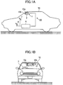
- FIGs. 1A and 1B illustrate one example where a vehicle control system 60 according to an embodiment is installed in a vehicle 70.
- the vehicle 70 is one example of a moving object
- the vehicle control system 60 is one example of a moving object control system.
- FIG. 1A is a side elevational view of the vehicle 70 including the vehicle control system 60
- FIG. 1B is a front elevational view of the vehicle 70.
- the vehicle control system 60 includes an object recognition apparatus 1 installed in a vehicle interior that is a space in the vehicle 70 accommodating occupants, a vehicle control apparatus 6, a steering wheel 7, and a brake pedal 8.
- the object recognition apparatus 1 has a function of photographing the forward direction of the vehicle 70.
- the object recognition apparatus 1 is installed on an inner surface of a windshield of the vehicle 70 near a rearview mirror. A configuration and operations of the object recognition apparatus 1 will be described later in detail.
- the object recognition apparatus 1 includes a body unit 2, one example of a photographing apparatus, and photographing units 10a and 10b fixed to the body unit 2.
- the photographing units 10a and 10b are fixed to the body unit 2 in such a manner as to be able to photograph a photographing target in the forward direction of the vehicle 70.
- the vehicle control apparatus 6 one example of a control unit, is an ECU (Electronic Control Unit) that carries out various vehicle control processes on the basis of recognition information received from the object recognition apparatus 1.
- ECU Electronic Control Unit
- the vehicle control apparatus 6 carries out, as examples of vehicle control processes, a steering control process of controlling a steering system (a control target) including the steering wheel 7 to avoid a collision with an obstacle; and a brake control process of controlling the brake pedal 8 (a control target) to cause the vehicle 70 to reduce the traveling speed or to stop on the basis of recognition information received from the object recognition apparatus 1.
- the object recognition apparatus 1 photographs the forward direction of the vehicle 70.
- embodiments are not limited to this manner.
- the object recognition apparatus 1 is installed in such a manner as to photograph the rearward direction or the sideward directions.
- the object recognition apparatus 1 can detect a subsequent vehicle or a pedestrian in the rearward direction, or another vehicle or a pedestrian in a sideward direction.
- the vehicle control apparatus 6 thus predicts a hazard at a time of lane change or lane merging, to carry out the above-mentioned vehicle control processes. Also, at a time of rearward traveling for parking the vehicle 70, the vehicle control apparatus 6 can carry out the above-mentioned vehicle control processes on the basis of recognized information that is output from the object recognition apparatus 1 for a rearward obstacle for a case of having determined that there is a likelihood of a collision with the rearward obstacle.
- FIG. 2 illustrates one example of a hardware configuration of the object recognition apparatus 1 according to the embodiment. With reference to FIG. 2 , the hardware configuration of the object recognition apparatus 1 will be described.
- the object recognition apparatus 1 includes a disparity value deriving unit 3 and a recognizing processing unit 5 inside the body unit 2.
- the disparity value deriving unit 3 derives a disparity value dp representing disparity concerning an object E from a plurality of images acquired from photographing the object E, and outputs a disparity image that represents the disparity value dp for each pixel.
- the disparity image is one example of "information of a position in a vertical direction, a position in a horizontal direction, and a position in a depth direction which are associated with each other".
- the recognizing processing unit 5 carries out an object recognizing process, and so forth, concerning an object such as a vehicle or a pedestrian appearing in a photographed image on the basis of the disparity image that is output from the disparity value deriving unit 3. Then, the recognizing processing unit 5 outputs recognition information that is a result of the object recognizing process to the vehicle control apparatus 6.
- image simply means a collection of information pieces that will be or will not be displayed on a display or the like.
- the disparity value deriving unit 3 includes the photographing unit 10a, the photographing unit 10b, a signal converting unit 20a, a signal converting unit 20b, and an image processing unit 30.
- the photographing unit 10a photographs a photographing target in the forward direction, to output an analog image signal.
- the photographing unit 10a includes a photographing lens 11a, a stop 12a, and an image sensor 13a.
- the photographing lens 11a refracts incident light to form an image of an object on the image sensor 13a.
- the stop 12a partially shuts off light that has passed through the photographing lens 11a, to adjust the light quantity that is input to the image sensor 13a.
- the image sensor 13a is a semiconductor device that converts light that has been incident on and has passed through the photographing lens 11a and has passed through the stop 12a, into an electric analog image signal.
- the image sensor 13a is implemented by, for example, a solid imaging device such as a CCD (Charge Coupled Device) or a CMOS (Complementary Metal Oxide Semiconductor).
- the photographing unit 10b photographs a photographing target in the forward direction, to generate an analog image signal.
- the photographing unit 10b includes a photographing lens 11b, a stop 12b, and an image sensor 13b.
- the photographing lens 11b, the stop 12b, and the image sensor 13b have functions the same as or similar to the functions of the photographing lens 11a, the stop 12a, and the image sensor 13a described above.
- the photographing lens 11a and the photographing lens 11b are installed in such a manner that the respective lens surfaces of the right camera (i.e., the photographing unit 10a) and the left camera (i.e., the photographing unit 10b) are on the same plane so as to be able to carry out photographing operations under the same conditions.
- the signal converting unit 20a converts the analog image signal generated by the photographing unit 10a into digital image data.
- the signal converting unit 20a includes a CDS (Correlated Double Sampling) circuit 21a, an AGC (Auto Gain Control) circuit 22a, an ADC (Analog Digital Converter) 23a, and a frame memory 24a.
- CDS Correlated Double Sampling
- AGC Auto Gain Control
- ADC Analog Digital Converter
- the CDS circuit 21a removes noise from the analog image signal generated by the image sensor 13a using a correlated double sampling circuit, a traverse differential filter, a longitudinal smoothing filter or the like.
- the AGC circuit 22a carries out gain control to control the intensity of the analog image signal from which the CDS circuit 21a has removed noise.
- the ADC 23a converts the analog image signal for which the AGC circuit 22a has carried out gain control into digital image data.
- the frame memory 24a stores the image data that is output from the ADC 23a.
- the signal converting unit 20b converts the analog image signal generated by the photographing unit 10b into digital image data.
- the signal converting unit 20b includes a CDS (Correlated Double Sampling) circuit 21b, an AGC (Auto Gain Control) circuit 22b, an ADC (Analog Digital Converter) 23b, and a frame memory 24b.
- the CDS circuit 21b, the AGC circuit 22b, the ADC 23b, and the frame memory 24b have functions the same as or similar to the functions of the CDS circuit 21a, the AGC circuit 22a, the ADC 23a, and the frame memory 24a described above.
- the image processing unit 30 carries out image processing on the image data that is output by the signal converting unit 20a, and carries out image processing on the image data that is output by the signal converting unit 20b.
- the image processing unit 30 includes a FPGA (Field Programmable Gate Array) 31, a CPU (Central Processing Unit) 32, a ROM (Read-Only Memory) 33, a RAM (Random Access Memory) 34, an I/F (InterFace) 35, and a bus line 39.
- FPGA Field Programmable Gate Array
- CPU Central Processing Unit
- ROM Read-Only Memory
- RAM Random Access Memory
- I/F InterFace
- the FPGA 31 is an integrated circuit, and carries out a process of deriving a disparity value dp in an image based on image data.
- the CPU 32 controls the functions of the disparity value deriving unit 3.
- the ROM 33 stores an image processing program to be executed by the CPU 32 to control the functions of the disparity value deriving unit 3.
- the RAM 34 is used as a work area of the CPU 32.
- the I/F 35 is an interface used for carrying out communications with an I/F 55 of the recognizing processing unit 5 via a communications line 4.
- the bus line 39 includes an address bus, a data bus, and so forth, and connects the FPGA 31, the CPU 32, the ROM 33, the RAM 34, and the I/F 35 as illustrated in FIG. 2 so that these circuits can carry out communications with each other, as illustrated in FIG. 2 .
- the image processing unit 30 includes the FPGA 31 as an integrated circuit used to derive disparity values dp.
- the image processing unit 30 is not limited to such a configuration. It is also possible that the image processing unit 30 includes another type of an integrated circuit such as an ASIC (Application Specific Integrated Circuit).
- ASIC Application Specific Integrated Circuit
- the recognizing processing unit 5 includes a FPGA 51, a CPU 52, a ROM 53, a RAM 54, the I/F 55, a CAN (Controller Area Network) I/F 58, and a bus line 59.
- the FPGA 51 is an integrated circuit, and carries out an object recognizing process for an object on the basis of the disparity image received from the image processing unit 30.
- the CPU 52 controls the functions of the recognizing processing unit 5.
- the ROM 53 stores an object recognizing processing program to be executed by the CPU 52 to carry out the object recognizing process of the recognizing processing unit 5.
- the RAM 54 is used as a work area of the CPU 52.
- the I/F 55 is an interface for implementing data communications with the I/F 35 of the image processing unit 30 via the communications line 4.
- the CAN I/F 58 is an interface for implementing communications with an external controller (for example, the vehicle control apparatus 6 illustrated in FIG. 2 ).
- the bus line 59 is connected to, for example, a CAN of the vehicle 70, or the like, and includes an address bus, a data bus, and so forth, to connect the FPGA 51, the CPU 52, the ROM 53, the RAM 54, the I/F 55, and the CAN I/F 58 in such a manner that these circuits can carry out communications with each other, as illustrated in FIG. 2 .
- the FPGA 51 in response to the disparity image being transmitted from the I/F 35 to the recognizing processing unit 5 via the communications line 4, the FPGA 51 carries out an object recognizing process for an object such as a pedestrian or a vehicle appearing in the photographed image on the basis of the disparity image, according to instructions sent from the CPU 52 of the recognizing processing unit 5.
- the above-mentioned programs are installable or executable files, which may be recorded in computer-readable recording media and may be circulated.
- These recording media are CD-ROMs (Compact Disc Read-Only Memories), SD (Secure Digital) memory cards, or the like.
- FIG. 3 illustrates one example of a functional block configuration of the object recognition apparatus 1 according to the embodiment.
- FIG. 3 a configuration and operations of functional blocks of the object recognition apparatus 1 will now be described.
- the object recognition apparatus 1 includes the disparity value deriving unit 3 and the recognizing processing unit 5.
- the disparity value deriving unit 3 includes an image acquiring unit 100a (a first photographing means), an image acquiring unit 100b (a second photographing means), converting units 200a and 200b, and a disparity value calculating processing unit 300, one example of a generating unit.
- At least some of the functional units of the object recognition apparatus 1 may be implemented by the FPGA 31 or the FPGA 51, or may be implemented as a result of a program being executed by the CPU 32 or the CPU 52.
- the image acquiring unit 100a and the image acquiring unit 100b are respective functional units that acquire luminance images from images taken by the right camera (the photographing unit 10a) and the left camera (the photographing unit 10b).
- the converting unit 200a is a functional unit that removes noise from the image data of the luminance image acquired by the image acquiring unit 100a, converts the noise-removed image data into digital image data, and outputs the digital image data.
- the converting unit 200a may be implemented by the signal converting unit 20a illustrated in FIG. 2 .
- the converting unit 200b is a functional unit that removes noise from the image data of the luminance image acquired by the image acquiring unit 100b, converts the noise-removed image data into digital image data, and outputs the digital image data.
- the converting unit 200b may be implemented by the signal converting unit 20b illustrated in FIG. 2 .
- the converting units 200a and 200b output respective sets of image data of the two luminance images.
- the respective sets of image data of the two luminance images may be simply referred to as luminance images.
- the luminance image photographed by the image acquiring unit 100a that is the right camera (the photographing unit 10a) is used as image data of a reference image Ia.
- the image data of the reference image Ia may be simply referred to as a reference image Ia.
- the luminance image photographed by the image acquiring unit 100b that is the left camera (the photographing unit 10b) is used as image data of a comparison image Ib.
- the image data of the comparison image Ib will be simply referred to as a comparison image Ib.
- the converting units 200a and 200b output the reference image Ia and the comparison image Ib, respectively, on the basis of the two luminance images that are output from the image acquiring units 100a and 100b, respectively.
- the disparity value calculating processing unit 300 derives the disparity values of the respective pixels of the reference image Ia on the basis of the reference image Ia and the comparison image Ib received from the converting units 200a and 200b, respectively, and generates a disparity image where the disparity values are associated with the respective pixels of the reference image Ia.
- FIG. 4 illustrates one example of a functional block configuration of the recognizing processing unit 5 of the object recognition apparatus 1 according to the embodiment. With reference to FIG. 4 , a configuration and operations of functional blocks of the recognizing processing unit 5 will now be described.
- the recognizing processing unit 5 includes a second generating unit 500, a clustering processing unit 510, and a tracking unit 530.
- the second generating unit 500 is a functional unit that receives the disparity image from the disparity value calculating processing unit 300, and receives the reference image Ia from the disparity value deriving unit 3, to generate a V-disparity map, a U-disparity map, a real U-disparity map, and so forth.
- the V-disparity map is one example of "information of a position in a vertical direction and a position in a depth direction which are associated with each other".
- Each of the U-disparity map and the real U-disparity map is one example of "information of a position in a horizontal direction and a position in a depth direction which are associated with each other".
- the second generating unit 500 includes a third generating unit 501, one example of an object moving surface estimating unit, a fourth generating unit 502, and a fifth generating unit 503.
- a configuration and operations of the second generating unit 500 of the recognizing processing unit 5 will now be described.
- FIG. 5 illustrates one example of a V-map VM generated from a disparity image.
- FIG. 6 illustrates examples UM and UM_H of a U-map generated from a disparity image.
- FIGs. 7A and 7B illustrate respective examples RM_H and RM of a real U-map generated from a U-map.
- the third generating unit 501 is a functional unit that generates a V-map VM that is a V-disparity map illustrated in FIG. 5 for detecting a road surface (one example of an object moving surface) from a disparity image received from the disparity value calculating processing unit 300.
- the V-disparity map is a two-dimensional histogram indicating the frequency distribution of the disparity values dp where the vertical axis corresponds to the y-axis (the vertical axis) of the reference image Ia such as an image illustrated in FIG. 5 , and the horizontal axis corresponds to the disparity values dp in the disparity image or the depth-direction distances.
- a road surface 600, a power pole 601, and an automobile 602 appear.
- the road surface 600 in the reference image Ia corresponds to a road surface part 600a in the V-map VM;
- the power pole 601 corresponds to a power pole part 601a;
- the automobile 602 corresponds to an automobile part 602a.
- the third generating unit 501 carries out straight-line approximation on positions estimated as a road surface in the generated V-map VM. If the road surface is flat, it is possible to approximate the positions of the road surface with a single straight line. However, if the road surface has various gradients, a corresponding section in the V-map VM is divided to implement straight-line approximation with high accuracy.
- the known Hough transform or a least squares method can be used.
- the power pole part 601a and the automobile part 602a which are the respective pixel blocks above the road surface part 600a, correspond to the power pole 601 and the automobile 602 that are respective objects on the road surface 600.
- the fourth generating unit 502 generates a U-disparity map as will be described later, only the information above the road surface is used for excluding noise.
- the height of the road surface is acquired.
- the heights of the objects above the road surface can be determined.
- a known method can be used to acquire the heights of the objects above the road surface.
- the V-map VM is converted into an image where the y-coordinates are converted into y-coordinates corresponding to actual heights. Then, the equation of a straight line expressing the estimated road surface is acquired.
- the symbol "f” denotes a value acquired from converting the focal length of the photographing units 10a and 10b into the same unit as the unit of (y' - y0).
- the symbol BF denotes a value acquired from multiplying the base length B of the photographing units 10a and 10b with the focal length f.
- the symbol "offset” denotes the disparity for a case where an object at an infinite distance is photographed.
- the fourth generating unit 502 is a functional unit that generates a U-map UM (a U-disparity map or a second frequency image) illustrated in FIG. 6 for recognizing objects.
- the fourth generating unit 502 uses only information concerning objects above a road surface detected from a V-map VM, i.e., uses information of a disparity image corresponding to a left-hand guard rail 611, a right-hand guard rail 612, an automobile 613, and an automobile 614 appearing in a reference image Ia illustrated in FIG. 6 , for example, to generate a U-map UM.
- the U-map UM is a two-dimensional histogram indicating a frequency distribution of disparity values dp where the horizontal axis corresponds to the x-axis (the positions in the horizontal direction) of the reference image Ia, and the vertical axis corresponds to the disparity values dp or the depth-direction distances in the disparity image.
- the left-hand guard rail 611 appearing in the reference image Ia illustrated in FIG. 6 corresponds to a left-hand guard rail part 611a in the U-map UM illustrated in FIG. 6 .
- the right-hand guard rail 612 corresponds to a right-hand guard rail part 612a;
- the automobile 613 corresponds to an automobile part 613a;
- the automobile 614 corresponds to an automobile part 614a.
- the fourth generating unit 502 generates a height U-map UM_H (that is another example of a U-disparity map) illustrated in FIG. 6 , for recognizing objects, with the use of only the information concerning the objects above the road surface detected from the V-map VM, i.e., with the use of the information of the disparity image corresponding to the left-hand guard rail 611, the right-hand guard rail 612, the automobile 613, and the automobile 614 appearing in the reference image Ia illustrated in FIG. 6 , for example.
- a height U-map UM_H that is another example of a U-disparity map
- the height U-map UM_H is an image where the horizontal axis corresponds to the x-axis (the positions in the horizontal direction) of the reference image Ia, the vertical axis corresponds to the disparity values dp or the depth-direction distances in the disparity image, and the pixel values correspond to the heights of the objects from the road surface. As the heights of the objects, the greatest heights of the respective objects from the road surface are used in the height U-map UM_H.
- the left-hand guard rail 611 appearing in the reference image Ia illustrated in FIG. 6 corresponds to a left-hand guard rail part 611b in the height U-map UM_H.
- the right-hand guard rail 612 corresponds to a right-hand guard rail part 612b;
- the automobile 613 corresponds to the automobile part 613b;
- the automobile 614 corresponds to the automobile part 614b.
- the fifth generating unit 503 generates a real height U-map RM_H, which is one example of a real U-disparity map, where the horizontal axis has been converted into the actual distance, as illustrated in FIG. 7A , from the height U-map UM_H generated by the fourth generating unit 502.
- the fifth generating unit 503 generates a real U-map RM, which is another example of a real U-disparity map, where the horizontal axis has been converted into the actual distance, as illustrated in FIG. 7B , from the U-map UM generated by the fourth generating unit 502.
- This process is carried out for generating a bird's-eye map (a bird's-eye image) for the purpose that an object can be easily detected. Therefore, the horizontal axis need not be an actual distance, and may be a measurement at least corresponding to an actual distance.
- the real height U-map RM_H and the real U-map RM are histograms where the horizontal axis indicates the actual distance in the direction (the horizontal direction) from the photographing unit 10b (the left camera) toward the photographing unit 10a (the right camera), and the vertical axis indicates the disparity values dp of the disparity image (or the depth-direction distances acquired from the disparity values dp being converted).
- the left-hand guard rail part 611b illustrated in the real height U-map RM_H of FIG. 7A corresponds to the left-hand guard rail part 611c in the real U-map RM of FIG. 7B .
- the right-hand guard rail part 612b corresponds to the right-hand guard rail part 612c
- the automobile part 613b corresponds to the automobile part 613c
- the automobile part 614b corresponds to the automobile part 614c.
- the fifth generating unit 503 generates the real height U-map RM_H and the real U-map RM that are bird's eye images.
- the fifth generating unit 503 does not thin out pixels for a distant location (where the disparity value dp is smaller). This is because, at a distant location, an object appears with a smaller size, therefore the information amount of the disparity information is smaller, and the resolution of the distance value is lower.
- the fifth generating unit 503 thins out pixels for a near location (where the disparity value dp is greater). This is because, at a near location, an object appears with a greater size, therefore the information amount of the disparity information is greater, and the resolution of the distance value is greater.
- An actual method of generating the real height U-map RM_H by the fifth generating unit 503 is not limited to the above-mentioned method using the height U-map UM_H. It is also possible that the fifth generating unit 503 generates the real height U-map RM_H directly from the disparity image.
- the second generating unit 500 can determine the position and width (i.e., xmin and xmax) of an object in the x-axis direction in the disparity image and the reference image Ia, from the generated height U-map UM_H or real height U-map RM_H. Also, the second generating unit 500 can acquire the actual depth of the object from the horizontal-axis information (i.e., dmin and dmax) of the height U-map UM_H or the real height U-map RM_H.
- the horizontal-axis information i.e., dmin and dmax
- the second generating unit 500 can determine the position and height of the object (i.e., ymin: "the y coordinate corresponding to the greatest height of the object from the road surface at the position at which the object has the greatest disparity value", and ymax: “the y coordinate indicating the height of the road surface at the position at which the greatest disparity value of the object is acquired”) in the y-axis direction in the disparity image and the reference image Ia, from the generated V-map VM.
- ymin the y coordinate corresponding to the greatest height of the object from the road surface at the position at which the object has the greatest disparity value
- ymax the y coordinate indicating the height of the road surface at the position at which the greatest disparity value of the object is acquired
- the second generating unit 500 can determine the actual size of the object in the x-axis direction and in the y-axis direction from the width (i.e., xmin and xmax) of the object in the x-axis direction, the height (i.e., ymin and ymax) of the object in the y-axis direction, and the corresponding disparity values dp determined from the disparity images.
- the second generating unit 500 uses the V-map VM, the height U-map UM_H, and the real height U-map RM_H, to determine the position, the actual width, height, and depth of an object appearing in the reference image Ia.
- the second generating unit 500 can determine the position of an object appearing in the reference image Ia, and therefore, the second generating unit 500 can determine the position of the object in the disparity image, and can determine the distance to the object.
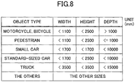
- FIG. 8 illustrates a method of determining an object type.
- the second generating unit 500 can determine the type of an object (an object type) with the use of the thus determined actual size of the object (the width, the height, and the depth) with reference to a table such as that illustrated in FIG. 8 .
- an object type the type of an object
- the object can be determined as a "standard-size car”.
- information such as a table illustrated in FIG. 8 where widths, heights, depths, and object types are associated together may be stored in the RAM 54, or the like.
- the clustering processing unit 510 illustrated in FIG. 4 is a functional unit of detecting an object such as a vehicle on the basis of each map that is input by the second generating unit 500. As illustrated in FIG. 4 , the clustering processing unit 510 includes an estimating unit 511, an object area detecting unit 512 (one example of a detecting unit), a determining unit 513, and a frame generating unit 514.
- the estimating unit 511 estimates an area that has a disparity corresponding to a road surface from a U-disparity map or a real U-disparity map.
- the reason why the estimating unit 511 thus carries out estimation is that there may be a case where the accuracy of detecting a road surface by the third generating unit 501 with the use of the V-map VM is not sufficiently high.
- the estimating unit 511 carries out the estimation with the use of a small real U-map acquired from reducing the size of a real U-disparity map by, for example, thinning out pixels will be described.
- the estimating unit 511 carries out the estimation with the use of a real U-disparity map.
- the estimating unit 511 carries out the estimation with the use of a U-disparity map. In this case, for example, it is possible that the estimating unit 511 carries out the process of converting the x coordinates in a U-disparity map into the actual distance in the horizontal direction or the like.
- the object area detecting unit 512 detects the depth, the width, and so forth of an object such as a vehicle above a road surface that is detected by the third generating unit 501 on the basis of a V-map VM.
- the object area detecting unit 512 uses a real U-disparity map, to carry out the detection.
- the object area detecting unit 512 uses a U-disparity map, to carry out the detection.
- the object area detecting unit 512 carries out a process of converting the x coordinates in the U-disparity map into the actual distance in the horizontal direction or the like.
- the determining unit 513 determines an object that is a road surface with the use of the estimation result of the estimating unit 511, from among the objects detected by the object area detecting unit 512. Then, the determining unit 513 removes the object that is thus determined as a road surface from among the objects detected by the object area detecting unit 512.
- the process that the determining unit 513 removes an object means a process that the determining unit 513 excludes the object from being processed in a subsequent process (for example, a tracking process) by, for example, setting a "remove flag" for the object.
- the frame generating unit 514 generates a detection frame for each of areas (recognized areas) in a disparity image Ip (or a reference image Ia) corresponding to objects other than the object determined as a road surface from among the objects detected by the object area detecting unit 512.
- the term "detection frame" represents a position and a size of a recognized object.
- a detection frame is information where the coordinates of the corners, the height, and the width of a rectangle that surrounds the object are associated together.
- the frame generating unit 514 outputs the generated detection frames to the tracking unit 530.
- the tracking unit 530 is a functional unit of carrying out a tracking process of tracking an object on the basis of recognized area information that is information concerning the object recognized by the clustering processing unit 510.
- recognized area information means information concerning an object recognized by the clustering processing unit 510.
- recognized area information includes the position and the size of a recognized object in a V-disparity map, a U-disparity map, a real U-disparity map, or the like, an identification number concerning a labelling process that will be described later, the above-described remove flag, and so forth.
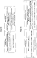
- FIG. 9 is a flowchart illustrating one example of a process of the clustering processing unit 510.
- step S11 the estimating unit 511 of the clustering processing unit 510 carries out a road surface area estimating process.
- the road surface area estimating process will be described later in detail.
- the object area detecting unit 512 of the clustering processing unit 510 carries out an object area detecting process (step S12).
- the "road surface area estimating process” and the “object area detecting process” may be carried out in parallel, or either one of the “road surface area estimating process” and the “object area detecting process” may be carried out first.
- the object area detecting process will be described later in detail.
- step S13 the determining unit 513 of clustering processing unit 510 carries out a road surface area removing process.
- the road surface area removing process will be described later in detail.
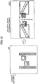
- FIG. 10 illustrates a process of generating detection frames. Using an object area that has been detected through the object area detecting process and that has not been removed through the road surface area removing process, as illustrated in FIG. 10 , a detection frame is generated for an area (a recognized area) corresponding to an object area in a disparity image Ip (or a reference image Ia).
- the determining unit 513 of the clustering processing unit 510 carries out a removing process (step S15). For example, in the removing process of step S15, it is possible that the objects that are classified as "THE OTHERS" in FIG. 8 in the object type classifying method illustrated in FIG. 8 from among the detected objects are removed.
- FIG. 11 is a flowchart illustrating one example of the road surface area estimating process.
- step S101 the estimating unit 511 generates a small real U-map that is an image acquired from thinning out pixels from a real U-map RM generated by the fifth generating unit 503.
- the small real U-map is generated by the fifth generating unit 503.
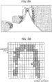
- FIGs. 12A-12C illustrate a labelling process.
- FIG. 12A illustrates one example of a reference image Ia.
- FIG. 12B illustrates one example of a small real U-map for a case where the reference image Ia is an image illustrated in FIG. 12A .
- a small real U-map is generated.
- the estimating unit 511 carries out a 4-neighborhood labelling process where, in the small real U-map, the same IDs are given to pixels (the disparity points) adjacent in the vertical directions (the depth directions) and in the horizontal directions, each of the pixels having a pixel value (a disparity frequency) greater than or equal to a predetermined value (for example, "1") (step S102).
- a predetermined value for example, "1"
- FIG. 12C illustrates an example where IDs are given to disparity points in the small real U-map.
- IDs (“1" or "2") are given to the disparity points adjacent in the vertical direction and in the horizontal direction in the small real U-map of FIG. 12B .
- An area where the respective pixels of each disparity point group to which the same IDs have been given are present may be referred to as an "isolated area (an object candidate)".
- the estimating unit 511 determines whether the currently photographed image relates to a curved environment (step S103). An example of a case for which the estimating unit 511 can determine that the currently photographed image relates to a curved environment will now be described.
- the left and right ends and the midpoint between the left and right ends are detected for each horizontal row of pixels included in each disparity point group (each isolated area) where the same IDs have been given to the pixels in step S102. Then, it is determined whether the difference in the average positions of the midpoints between a nearer zone and a farther zone is greater than or equal to a threshold, and it is determined whether the varying direction of the left ends and the varying direction of the right ends along the depth direction are the same as one another. For a case where both the determination results are affirmative, the estimating unit 511 determines that the currently photographed image relates to a curved environment, in this example.
- the estimating unit 511 can determine whether the currently photographed image relates to a curved environment in consideration of the respective determination results concerning the isolated areas comprehensively, for example.
- the estimating unit 511 determines that the currently photographed image relates to a curved environment for a case where, in the small real U-map, image processing is carried out on the currently photographed image to recognize a white line that separates lanes, for example, and the curving degree of the detected white line is greater than or equal to a threshold. It is also possible that the estimating unit 511 determines that the currently photographed image relates to a curved environment on the basis of the steering angle of the steering wheel acquired from an ECU of the vehicle.
- step S103 When the currently photographed image relates to a curved environment (YES in step S103), the process ends. Also, in the current process of the clustering processing unit 510 of FIG. 9 , the road surface area removing process (step S13) will be skipped. This is because when the currently photographed image relates to a curved environment, the remaining process of the road surface area estimating process (step S11 illustrated in FIG. 11 ) and the entirety of the road surface area removing process (step S13 illustrated in FIG. 18 ) may be inadequate for the currently photographed image.
- the estimating unit 511 extracts one or more disparity point groups to be processed, from the disparity point groups in each of which the same IDs have been given to the pixels, on the basis of the widths and the depths of the disparity point groups (step S104). Note that steps S104-S110 are carried out for each isolated area.
- FIG. 13 illustrates one example of thresholds to be used to thus extract disparity point groups to be processed.
- a disparity point group having the width (the length in the horizontal direction) greater than or equal to an amount corresponding to one lane (for example, 3 m), and the depth greater than or equal to a predetermined value (for example, 10 m) is extracted as a disparity point group to be processed.
- step S13 Each of the disparity point groups thus extracted to be processed will be processed in the road surface area removing process (step S13 illustrated in FIG. 18 ) of determining whether the disparity point group corresponds to a road surface.
- the disparity point groups that have not been extracted in step S104 will be removed from being further processed in the road surface estimating process of FIG. 11 , and also, will be removed from being processed in the road surface area removing process (step S13).
- a disparity point group having the width greater than or equal to, for example, 3 m, and the depth greater than or equal to, for example, 10 m is too large to be an object such as a vehicle. Therefore, such a disparity point group can be estimated as an object other than a vehicle, and can be estimated as a road surface, or the like.
- a vehicle or the like having the depth, for example, greater than or equal to 10 m occurs in the forward direction. This is because a vehicle or the like has a back face and a side face each extending approximately upright with respect to a road surface, and the body of the vehicle or the like extending from the back face and the side face is not photographed. Therefore, there is a very small likelihood that, in a bird's eye image such as a small real U-map, a vehicle or the like having such a depth is detected. Therefore, as mentioned above, an isolated area having the width greater than or equal to 3 m and the depth greater than or equal to 10 m, for example, is extracted as a disparity point group to be processed.
- the estimating unit 511 determines whether the currently photographed image relates to a narrow road environment (step S105).
- a rectangle that circumscribes each disparity point group where the same IDs have been given to the pixels is generated. Then, it is determined whether each of the respective depths of the two areas acquired from dividing the rectangle in such a manner that the rectangle is divided by a centerline between the left and right ends of the rectangle is greater than or equal to a predetermined value. For a case where the determination result is affirmative, the estimating unit 511 determines that the currently photographed image relates to a narrow road environment, in this example.
- disparity points corresponding to roadside objects such as plants are joined to disparity points corresponding to a road surface that, for example, slopes upward in the forward direction (i.e., these disparity points are given the same IDs) in a bird's eye image such as a small real U-map.
- a road surface may be erroneously detected as an object other than a road surface.
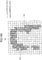
- a disparity point group where the same IDs have been given to the pixels may have a horseshoe shape (or a U-shape) in a bird's eye image such as a small real U-map as illustrated in FIG. 12B .
- the above-mentioned determination method of dividing a rectangle that circumscribes each disparity point group at a centerline between the left and right ends of the rectangle, and using the respective depths of the two areas acquired from dividing the rectangle is advantageous.
- step S105 is used widely for an environment where the width of a location where a vehicle is traveling is narrow and objects such as plants occur in a row at each of the left and right sides.
- the estimating unit 511 determines whether each disparity point group is a road surface candidate (whether there are road surface candidates). In more detail, for each disparity point group where the same IDs have been given to the pixels, the estimating unit 511 calculates the horizontal dimension of the consecutive disparity points that have a horizontal dimension greater than or equal to a predetermined value. Then, the disparity point groups each having a large horizontal dimension with respect to a predetermined amount are determined as road surface candidates (step S106).
- the estimating unit 511 extracts only disparity point groups each continuing horizontally on the order of a certain amount (i.e., extracts only isolated areas each extending in a horizontal direction on the order of a certain amount), and thus, uses such determination conditions to determine whether a disparity point group is a road surface candidate.
- FIGs. 14A and 14B illustrate a process of calculating widths of disparity point groups branched into left and right portions.
- the estimating unit 511 extracts a horizontal consecutive disparity point row extending for the greatest amount.
- the horizontal disparity point row is regarded as consecutive because there is a likelihood that such a break occurs due to noise.
- the estimating unit 511 removes the horizontal disparity point rows each having a width (a length in the horizontal direction) smaller than or equal to a predetermined value (for example, corresponding to two pixels) from among the extracted horizontal disparity point rows, as illustrated in FIG. 14B . Then, from among the remaining horizontal disparity point rows, horizontal disparity point rows consecutive in the vertical direction are collected together to belong to a single common group.
- a predetermined value for example, corresponding to two pixels
- the same IDs 701, 702, or 703 are given to each of the thus acquired groups 701, 702, and 703.
- the average of the widths is calculated. For a case where any one of the calculated averages is greater than or equal to a predetermined threshold, the estimating unit 511 can determine that a road surface candidate occurs in the currently photographed image, for example.
- step S107 the estimating unit 511 determines a processing type concerning a road surface area removing process (that will be described later with reference to FIG. 18 ) on the basis of whether the currently photographed image relates to a narrow road (determined in step S105) and of whether a road surface candidate occurs in the currently photographed image (determined in step S106).
- a processing type concerning the road surface area removing process is determined on the basis of the shapes of the isolated areas determined as object candidates.
- Determination of a processing type in step S107 on the basis of determination results includes determination of thresholds to be used to determine a processing type (step S107A), and determination of a processing type for each isolated area on the basis of the thus determined thresholds (step S107B).
- FIG. 15 illustrates one example of thresholds to be used to determine a processing type.
- relatively moderate depth thresholds are selected.
- the relatively moderate depth thresholds include a first threshold 10 m and a second threshold 5 m.
- relatively strict depth thresholds are selected.
- the relatively strict depth thresholds include a first threshold 20 m and a second threshold 10 m.
- the relatively moderate depth thresholds are used.
- a processing type such that a processing result of an "object area detecting process" (described later in detail) can be easily removed (i.e., an object area is easily detected as a road surface and therefore, can be easily removed from being further processed) is selected.
- the shape is determined as a road surface candidate in step S106, and relatively moderate (small) thresholds are selected as illustrate in FIG. 15 .
- relatively moderate (small) thresholds are selected as illustrate in FIG. 15 .
- the estimating unit 511 determines in step S107B a processing type to be used for each isolated area on the basis of the thus determined thresholds.
- FIG. 16 illustrates one example of determining a processing type.
- the estimating unit 511 determines to select a processing type (hereinafter, referred to as "processing A") such that, for the area of the disparity point group, the processing result of the object area detecting process of FIG. 17 will be removed from being further processed without a check of the processing result.
- processing A a processing type
- the estimating unit 511 determines to select a processing type (hereinafter, referred to as "processing B") such that, for the area of the disparity point group, the processing result of the object area detecting process of FIG. 17 will be checked.
- processing B a processing type
- the thresholds of one type i.e., the relatively moderate depth thresholds or the relatively strict depth thresholds
- selecting a different process using the selected thresholds it is possible to select a suitable process depending on a likelihood as to whether a road surface has been erroneously detected as an object other than a road surface.
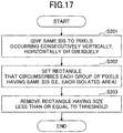
- FIG. 17 is a flowchart illustrating one example of the object area detecting process.
- an object area is extracted from a real height U-map RM_H.
- an object area can be extracted with the use of disparity points having heights from a road surface greater than or equal to a predetermined value from among the disparity points included in a real U-map RM. It is also possible to carry out the same process as will now be described with the use of any type of information (a bird's eye image) in which horizontal positions are associated with depth-direction positions.
- step S201 the object area detecting unit 512 carries out a 8-neighborhood labelling process of giving the same IDs to the pixels adjacent in the vertical directions, the horizontal directions, and the oblique directions in a real height U-map RM_H, each of the pixels having a pixel value greater than or equal to a predetermined value.
- this labelling process a known process can be used.
- step S202 the object area detecting unit 512 sets a rectangle that circumscribes each of the pixel groups in each of which the same IDs have been given to the pixels (each of the isolated areas).
- the object area detecting unit 512 removes the pixel groups each having the rectangle that has a size less than or equal to a predetermined value (step S203). This is because the pixel groups each having the rectangle that has the size less than or equal to the predetermined value can be determined as noise.
- the object area detecting process is not limited to the process described above with reference to FIG. 17 . As long as it is possible to detect an area representing an object based on a disparity image, any other known technology may be used.
- FIG. 18 is a flowchart illustrating one example of the road surface area removing process. Note that, the process that will now be described with reference to FIG. 18 is carried out for each of the isolated areas detected in the object area detecting process described above with reference to FIG. 17 . Below, areas to be processed from among the respective isolated areas detected in the object area detecting process will be referred to as "target areas”.
- step S301 the determining unit 513 calculates an area value for overlap (an overlap area value) between the rectangle that circumscribes the target area and a rectangle (hereinafter, which may be referred to as a "road surface estimated area") that circumscribes the area in the real U-map RM corresponding to each of the isolated areas that have been extracted from the small real U-map in steps S102, further extracted in step S104 as the disparity point groups to be processed, and have the processing type determined in step S107 of the road surface area estimating process of FIG. 11 .
- an area value for overlap an overlap area value between the rectangle that circumscribes the target area and a rectangle (hereinafter, which may be referred to as a "road surface estimated area") that circumscribes the area in the real U-map RM corresponding to each of the isolated areas that have been extracted from the small real U-map in steps S102, further extracted in step S104 as the disparity point groups to be processed, and have the processing type determined in step S107 of the road surface area estimating process of FIG.
- FIG. 19 illustrates a method of calculating an area value of an area where rectangles overlap.
- the determining unit 513 calculates the number of pixels where the rectangle 711 that circumscribes the target area overlaps with the rectangle 712 that circumscribes each "road surface estimated area" mentioned above.
- the overlap area value is calculated as a result of the number of pixels 714 in the horizontal direction of the overlap area 713 being multiplied by the number of pixels 715 in the vertical direction of the overlap area 713.
- the greatest area value of the respective area values of the overlap areas 713 corresponding to the plurality of rectangles 712 will be used as the overlap area value for the target area.
- step S302 the determining unit 513 acquires the processing type determined in step S107 of FIG. 11 for the road surface estimated area corresponding to the greatest area value calculated in step S301.
- the determining unit 513 determines whether the area value of the target area and the overlap area value satisfy predetermined conditions (step S303). In step S303, for example, the determining unit 513 determines whether the overlap area value is greater than or equal to a predetermined percentage of the area value of the target area.
- the determining unit 513 removes the target area from being further processed (step S304), and ends the process for this target area.
- the determining unit 513 ends the process for this target area.
- the determining unit 513 need not carry out such a determination process as step S303 described above using a relationship between the area value of the target area and the overlap area value.
- the point of a case of the processing A is that the target area can be removed from being further processed in step S304 without a process of checking the processing result of the object area detecting process of FIG. 17 that is carried out for a case of the processing B of step S302.
- An example of the process of checking the processing result of the object area detecting process is a process of determining whether the object corresponds to an object of a predetermined type such as a vehicle.
- the determining unit 513 first determines whether the target area corresponds to a vehicle or the like. In more detail, the determining unit 513 determines whether the size of the target area and an adjacent disparity distribution of the target area satisfy predetermined conditions (step S305).
- the determining unit 513 can determine that the predetermined conditions are satisfied.
- the determining unit 513 can determine that the predetermined conditions are satisfied.
- the determining unit 513 can determine that the predetermined conditions are satisfied.
- step S305 For a case where the determining unit 513 determines that the size of the target area and the adjacent disparity distribution satisfy the predetermined conditions (Yes in step S305), the determining unit 513 proceeds to step S304.
- the determining unit 513 determines that the size of the target area and the adjacent disparity distribution do not satisfy the predetermined conditions (No in step S305).
- the determining unit 513 ends the process.
- FIG. 20 illustrates a result of the above-described road surface area removing process. Note that although two detection frames 721 and 722 are illustrated in FIG. 20 , the detection frame 721 is not actually displayed, and is illustrated for the explanation purpose, as will now be described.
- FIG. 20 illustrates a case as if, concerning the reference image Ia of FIG. 12A , the frame generating unit 514 were to generate the detection frames 721 and 722 for areas (recognized areas) in a disparity image Ip (or a reference image Ia) corresponding to object areas detected by the object area detecting unit 512.
- the detection frame 721 corresponding to the area determined as corresponding to a road surface by the determining unit 513 is not actually generated in step S14 of FIG. 9 due to the above-described road surface area removing process of FIG. 18 (i.e., step S13 of FIG. 9 ) .
- recognized area information concerning the detection frame 721 that may be otherwise generated on the basis of disparity of the road surface in the forward direction is not actually output to the tracking unit 530 of FIG. 4 from the frame generating unit 514.
- the recognized area information concerning the detection frame 721 (corresponding to the road surface) is excluded from being processed in a tracking process of tracking an object carried out by the tracking unit 530.
- the third generating unit 501 may erroneously estimate the height of the road surface through straight approximation or the like carried out on a V-map VM, and as a result, disparity points according to the road surface may undesirably appear in a U-map UM.
- the object is determined as a road surface, and as a result, the object is removed from being further processed according to FIGs. 15 and 16 described above.
- the object is prevented from being further processed according to FIGs. 15 and 16 described above.
- a disparity image is used as one example of a distance image according to the embodiment.
- an actual method of acquiring a distance image is not limited to this manner.
- a distance image by integrating a disparity image acquired with the use of a stereo camera with distance information generated with the use of a detection apparatus such as millimeter radar, laser radar, or the like.
- a stereo camera and a detection apparatus such as millimeter radar, laser radar, or the like together, and combining the object detection result of the stereo camera with the object detection result of the detection apparatus.
- functional parts that implement at least some processes of the respective functional parts of the disparity value calculating processing unit 300, the second generating unit 500, the clustering processing unit 510, the tracking unit 530, and so forth of the object recognition apparatus 1 may be implemented by cloud computing configured by one or more computers.
- the object recognition apparatus 1 is installed in the vehicle 70 that is an automobile.
- the object recognition apparatus 1 may be installed in another vehicle such as a motorcycle, a bicycle, a wheelchair, an agricultural cultivator, or the like.
- the object recognition apparatus 1 may be installed not only in a vehicle as one example of a moving object but also in another moving object such as a robot.
- the program is provided after being stored in a ROM or the like.
- the programs executed in the object recognition apparatuses 1 may be files of an installable or executable type which may be provided after being recorded in computer-readable recording media such as CD-ROMs, flexible disks (FD), CD-Rs, DVDs, or the like.
- the programs executed in the object recognition apparatuses 1 according to the above-described embodiments may be provided in such a manner of being stored in computers connected to a network such as the Internet, and of being downloaded via the network.
- the programs executed in the object recognition apparatuses 1 according to the above-described embodiments may be provided or delivered via a network such as the Internet.
- the programs executed in the object recognition apparatuses 1 according to the above-described embodiments are configured with modules that include at least some of the above-described functional units.
- the CPU 52 and the CPU 32 as actual hardware read the programs from the ROM 53 and the ROM 33, and execute the programs so that the above-described functional units are loaded and generated in the main storages (the RAM 54, the RAM 34, and so forth).
Landscapes
- Engineering & Computer Science (AREA)
- Physics & Mathematics (AREA)
- General Physics & Mathematics (AREA)
- Multimedia (AREA)
- Theoretical Computer Science (AREA)
- Computer Vision & Pattern Recognition (AREA)
- Image Analysis (AREA)
- Length Measuring Devices By Optical Means (AREA)
- Traffic Control Systems (AREA)
- Image Processing (AREA)
Applications Claiming Priority (2)
| Application Number | Priority Date | Filing Date | Title |
|---|---|---|---|
| JP2016229467 | 2016-11-25 | ||
| JP2017181108A JP6992356B2 (ja) | 2016-11-25 | 2017-09-21 | 情報処理装置、撮像装置、機器制御システム、移動体、情報処理方法およびプログラム |
Publications (2)
| Publication Number | Publication Date |
|---|---|
| EP3336754A2 true EP3336754A2 (fr) | 2018-06-20 |
| EP3336754A3 EP3336754A3 (fr) | 2018-09-05 |
Family
ID=60473289
Family Applications (1)
| Application Number | Title | Priority Date | Filing Date |
|---|---|---|---|
| EP17201979.6A Ceased EP3336754A3 (fr) | 2016-11-25 | 2017-11-16 | Appareil de traitement d'informations, appareil photographique, système de commande d'objet mobile, objet mobile, procédé de traitement d'informations et programme |
Country Status (1)
| Country | Link |
|---|---|
| EP (1) | EP3336754A3 (fr) |
Cited By (4)
| Publication number | Priority date | Publication date | Assignee | Title |
|---|---|---|---|---|
| CN108960096A (zh) * | 2018-06-22 | 2018-12-07 | 杭州晶智能科技有限公司 | 基于立体视觉和红外成像的人体识别方法 |
| CN110132288A (zh) * | 2019-05-08 | 2019-08-16 | 南京信息工程大学 | 一种等宽路面的微型车视觉导航方法 |
| US20230351638A1 (en) * | 2022-04-29 | 2023-11-02 | Nvidia Corporation | Detecting hazards based on disparity maps using computer vision for autonomous machine systems and applications |
| US12676008B2 (en) | 2022-04-29 | 2026-07-07 | Nvidia Corporation | Detecting hazards based on disparity maps using machine learning for autonomous machine systems and applications |
Citations (1)
| Publication number | Priority date | Publication date | Assignee | Title |
|---|---|---|---|---|
| JP2016062356A (ja) | 2014-09-18 | 2016-04-25 | トヨタ自動車株式会社 | 立体物検出装置 |
Family Cites Families (1)
| Publication number | Priority date | Publication date | Assignee | Title |
|---|---|---|---|---|
| JP6550881B2 (ja) * | 2014-07-14 | 2019-07-31 | 株式会社リコー | 立体物検出装置、立体物検出方法、立体物検出プログラム、及び移動体機器制御システム |
-
2017
- 2017-11-16 EP EP17201979.6A patent/EP3336754A3/fr not_active Ceased
Patent Citations (1)
| Publication number | Priority date | Publication date | Assignee | Title |
|---|---|---|---|---|
| JP2016062356A (ja) | 2014-09-18 | 2016-04-25 | トヨタ自動車株式会社 | 立体物検出装置 |
Cited By (6)
| Publication number | Priority date | Publication date | Assignee | Title |
|---|---|---|---|---|
| CN108960096A (zh) * | 2018-06-22 | 2018-12-07 | 杭州晶智能科技有限公司 | 基于立体视觉和红外成像的人体识别方法 |
| CN108960096B (zh) * | 2018-06-22 | 2021-08-17 | 深圳市恒天伟焱科技股份有限公司 | 基于立体视觉和红外成像的人体识别方法 |
| CN110132288A (zh) * | 2019-05-08 | 2019-08-16 | 南京信息工程大学 | 一种等宽路面的微型车视觉导航方法 |
| US20230351638A1 (en) * | 2022-04-29 | 2023-11-02 | Nvidia Corporation | Detecting hazards based on disparity maps using computer vision for autonomous machine systems and applications |
| US12482137B2 (en) * | 2022-04-29 | 2025-11-25 | Nvidia Corporation | Detecting hazards based on disparity maps using computer vision for autonomous machine systems and applications |
| US12676008B2 (en) | 2022-04-29 | 2026-07-07 | Nvidia Corporation | Detecting hazards based on disparity maps using machine learning for autonomous machine systems and applications |
Also Published As
| Publication number | Publication date |
|---|---|
| EP3336754A3 (fr) | 2018-09-05 |
Similar Documents
| Publication | Publication Date | Title |
|---|---|---|
| US10580155B2 (en) | Image processing apparatus, imaging device, device control system, frequency distribution image generation method, and recording medium | |
| EP3382639B1 (fr) | Dispositif de traitement d'images, dispositif de capture d'images, système de commande d'appareil, procédé de génération de données de distribution, et programme | |
| JP6795027B2 (ja) | 情報処理装置、物体認識装置、機器制御システム、移動体、画像処理方法およびプログラム | |
| EP3545464B1 (fr) | Dispositif de traitement d'informations, dispositif d'imagerie, système de commande d'équipement, objet mobile, procédé de traitement d'informations et support d'enregistrement lisible par ordinateur | |
| US10885351B2 (en) | Image processing apparatus to estimate a plurality of road surfaces | |
| JP6705496B2 (ja) | 画像処理装置、撮像装置、移動体機器制御システム、移動体、画像処理方法、及びプログラム | |
| US10832431B2 (en) | Image processing apparatus, object recognition apparatus, equipment control system, image processing method, and computer-readable recording medium | |
| US11691585B2 (en) | Image processing apparatus, imaging device, moving body device control system, image processing method, and program product | |
| JP6705497B2 (ja) | 画像処理装置、撮像装置、移動体機器制御システム、画像処理方法、プログラム、及び移動体 | |
| JP6816401B2 (ja) | 画像処理装置、撮像装置、移動体機器制御システム、画像処理方法、及びプログラム | |
| EP3392830B1 (fr) | Dispositif de traitement d'images, dispositif de reconnaissance d'objets, système de commande d'appareil, procédé de traitement d'images et programme | |
| JP6855325B2 (ja) | 画像処理装置、ステレオカメラシステム、移動体、路面形状検出方法およびプログラム | |
| US10628960B2 (en) | Information processing apparatus, imaging apparatus, device control system, moving object, information processing method, and recording medium | |
| EP3389009B1 (fr) | Dispositif de traitement d'image, dispositif de reconnaissance d'objet, système de commande d'appareil, procédé de traitement d'image et programme | |
| US11527075B2 (en) | Information processing apparatus, imaging apparatus, apparatus control system, movable object, information processing method, and computer-readable recording medium | |
| JP6992356B2 (ja) | 情報処理装置、撮像装置、機器制御システム、移動体、情報処理方法およびプログラム | |
| EP3540643A1 (fr) | Appareil de traitement d'images et procédé de traitement d'images | |
| JP6711128B2 (ja) | 画像処理装置、撮像装置、移動体機器制御システム、画像処理方法、及びプログラム | |
| EP3287948B1 (fr) | Appareil de traitement d'images, système de commande d'appareil de corps mobile, procédé de traitement d'images et programme | |
| JP6763198B2 (ja) | 画像処理装置、撮像装置、移動体機器制御システム、画像処理方法、及びプログラム | |
| EP3327696B1 (fr) | Appareil de traitement d'informations, dispositif d'imagerie, système de commande de dispositif, corps mobile, procédé de traitement d'informations et programme | |
| EP3540642A1 (fr) | Dispositif de traitement d'images, dispositif de reconnaissance d'objets, système de commande de dispositifs, objet mobile, procédé de traitement d'images et support d'enregistrement lisible sur ordinateur | |
| WO2018097269A1 (fr) | Dispositif de traitement d'informations, dispositif d'imagerie, système de commande d'équipement, objet mobile, procédé de traitement d'informations et support d'enregistrement lisible par ordinateur | |
| JP6943092B2 (ja) | 情報処理装置、撮像装置、機器制御システム、移動体、情報処理方法、及び、情報処理プログラム |
Legal Events
| Date | Code | Title | Description |
|---|---|---|---|
| PUAI | Public reference made under article 153(3) epc to a published international application that has entered the european phase |
Free format text: ORIGINAL CODE: 0009012 |
|
| STAA | Information on the status of an ep patent application or granted ep patent |
Free format text: STATUS: REQUEST FOR EXAMINATION WAS MADE |
|
| 17P | Request for examination filed |
Effective date: 20171116 |
|
| AK | Designated contracting states |
Kind code of ref document: A2 Designated state(s): AL AT BE BG CH CY CZ DE DK EE ES FI FR GB GR HR HU IE IS IT LI LT LU LV MC MK MT NL NO PL PT RO RS SE SI SK SM TR |
|
| AX | Request for extension of the european patent |
Extension state: BA ME |
|
| PUAL | Search report despatched |
Free format text: ORIGINAL CODE: 0009013 |
|
| AK | Designated contracting states |
Kind code of ref document: A3 Designated state(s): AL AT BE BG CH CY CZ DE DK EE ES FI FR GB GR HR HU IE IS IT LI LT LU LV MC MK MT NL NO PL PT RO RS SE SI SK SM TR |
|
| AX | Request for extension of the european patent |
Extension state: BA ME |
|
| RIC1 | Information provided on ipc code assigned before grant |
Ipc: G06K 9/00 20060101AFI20180731BHEP |
|
| STAA | Information on the status of an ep patent application or granted ep patent |
Free format text: STATUS: EXAMINATION IS IN PROGRESS |
|
| 17Q | First examination report despatched |
Effective date: 20200122 |
|
| RAP1 | Party data changed (applicant data changed or rights of an application transferred) |
Owner name: RICOH COMPANY, LTD. |
|
| STAA | Information on the status of an ep patent application or granted ep patent |
Free format text: STATUS: THE APPLICATION HAS BEEN REFUSED |
|
| 18R | Application refused |
Effective date: 20210201 |