EP3336859B1 - Procédé pour prédire une résistance d'un joint de soudure ultrasonique - Google Patents
Procédé pour prédire une résistance d'un joint de soudure ultrasonique Download PDFInfo
- Publication number
- EP3336859B1 EP3336859B1 EP16204392.1A EP16204392A EP3336859B1 EP 3336859 B1 EP3336859 B1 EP 3336859B1 EP 16204392 A EP16204392 A EP 16204392A EP 3336859 B1 EP3336859 B1 EP 3336859B1
- Authority
- EP
- European Patent Office
- Prior art keywords
- wire
- cable
- contaminant
- weight
- accordance
- Prior art date
- Legal status (The legal status is an assumption and is not a legal conclusion. Google has not performed a legal analysis and makes no representation as to the accuracy of the status listed.)
- Active
Links
Images

Classifications
-
- B—PERFORMING OPERATIONS; TRANSPORTING
- B23—MACHINE TOOLS; METAL-WORKING NOT OTHERWISE PROVIDED FOR
- B23K—SOLDERING OR UNSOLDERING; WELDING; CLADDING OR PLATING BY SOLDERING OR WELDING; CUTTING BY APPLYING HEAT LOCALLY, e.g. FLAME CUTTING; WORKING BY LASER BEAM
- B23K31/00—Processes relevant to this subclass, specially adapted for particular articles or purposes, but not covered by any single one of main groups B23K1/00 - B23K28/00
- B23K31/12—Processes relevant to this subclass, specially adapted for particular articles or purposes, but not covered by any single one of main groups B23K1/00 - B23K28/00 relating to investigating the properties, e.g. the weldability, of materials
- B23K31/125—Weld quality monitoring
-
- H—ELECTRICITY
- H01—ELECTRIC ELEMENTS
- H01R—ELECTRICALLY-CONDUCTIVE CONNECTIONS; STRUCTURAL ASSOCIATIONS OF A PLURALITY OF MUTUALLY-INSULATED ELECTRICAL CONNECTING ELEMENTS; COUPLING DEVICES; CURRENT COLLECTORS
- H01R43/00—Apparatus or processes specially adapted for manufacturing, assembling, maintaining, or repairing of line connectors or current collectors or for joining electric conductors
- H01R43/02—Apparatus or processes specially adapted for manufacturing, assembling, maintaining, or repairing of line connectors or current collectors or for joining electric conductors for soldered or welded connections
-
- G—PHYSICS
- G01—MEASURING; TESTING
- G01N—INVESTIGATING OR ANALYSING MATERIALS BY DETERMINING THEIR CHEMICAL OR PHYSICAL PROPERTIES
- G01N5/00—Analysing materials by weighing, e.g. weighing small particles separated from a gas or liquid
- G01N5/02—Analysing materials by weighing, e.g. weighing small particles separated from a gas or liquid by absorbing or adsorbing components of a material and determining change of weight of the adsorbent, e.g. determining moisture content
-
- B—PERFORMING OPERATIONS; TRANSPORTING
- B23—MACHINE TOOLS; METAL-WORKING NOT OTHERWISE PROVIDED FOR
- B23K—SOLDERING OR UNSOLDERING; WELDING; CLADDING OR PLATING BY SOLDERING OR WELDING; CUTTING BY APPLYING HEAT LOCALLY, e.g. FLAME CUTTING; WORKING BY LASER BEAM
- B23K20/00—Non-electric welding by applying impact or other pressure, with or without the application of heat, e.g. cladding or plating
- B23K20/10—Non-electric welding by applying impact or other pressure, with or without the application of heat, e.g. cladding or plating making use of vibrations, e.g. ultrasonic welding
-
- G—PHYSICS
- G01—MEASURING; TESTING
- G01G—WEIGHING
- G01G19/00—Weighing apparatus or methods adapted for special purposes not provided for in the preceding groups
- G01G19/40—Weighing apparatus or methods adapted for special purposes not provided for in the preceding groups with provisions for indicating, recording, or computing price or other quantities dependent on the weight
- G01G19/413—Weighing apparatus or methods adapted for special purposes not provided for in the preceding groups with provisions for indicating, recording, or computing price or other quantities dependent on the weight using electromechanical or electronic computing means
- G01G19/414—Weighing apparatus or methods adapted for special purposes not provided for in the preceding groups with provisions for indicating, recording, or computing price or other quantities dependent on the weight using electromechanical or electronic computing means using electronic computing means only
-
- G—PHYSICS
- G01—MEASURING; TESTING
- G01N—INVESTIGATING OR ANALYSING MATERIALS BY DETERMINING THEIR CHEMICAL OR PHYSICAL PROPERTIES
- G01N1/00—Sampling; Preparing specimens for investigation
- G01N1/28—Preparing specimens for investigation including physical details of (bio-)chemical methods covered elsewhere, e.g. G01N33/50, C12Q
- G01N1/34—Purifying; Cleaning
-
- G—PHYSICS
- G01—MEASURING; TESTING
- G01N—INVESTIGATING OR ANALYSING MATERIALS BY DETERMINING THEIR CHEMICAL OR PHYSICAL PROPERTIES
- G01N5/00—Analysing materials by weighing, e.g. weighing small particles separated from a gas or liquid
- G01N5/04—Analysing materials by weighing, e.g. weighing small particles separated from a gas or liquid by removing a component, e.g. by evaporation, and weighing the remainder
-
- H—ELECTRICITY
- H01—ELECTRIC ELEMENTS
- H01R—ELECTRICALLY-CONDUCTIVE CONNECTIONS; STRUCTURAL ASSOCIATIONS OF A PLURALITY OF MUTUALLY-INSULATED ELECTRICAL CONNECTING ELEMENTS; COUPLING DEVICES; CURRENT COLLECTORS
- H01R43/00—Apparatus or processes specially adapted for manufacturing, assembling, maintaining, or repairing of line connectors or current collectors or for joining electric conductors
- H01R43/02—Apparatus or processes specially adapted for manufacturing, assembling, maintaining, or repairing of line connectors or current collectors or for joining electric conductors for soldered or welded connections
- H01R43/0207—Ultrasonic-, H.F.-, cold- or impact welding
-
- B—PERFORMING OPERATIONS; TRANSPORTING
- B23—MACHINE TOOLS; METAL-WORKING NOT OTHERWISE PROVIDED FOR
- B23K—SOLDERING OR UNSOLDERING; WELDING; CLADDING OR PLATING BY SOLDERING OR WELDING; CUTTING BY APPLYING HEAT LOCALLY, e.g. FLAME CUTTING; WORKING BY LASER BEAM
- B23K2101/00—Articles made by soldering, welding or cutting
- B23K2101/32—Wires
-
- B—PERFORMING OPERATIONS; TRANSPORTING
- B23—MACHINE TOOLS; METAL-WORKING NOT OTHERWISE PROVIDED FOR
- B23K—SOLDERING OR UNSOLDERING; WELDING; CLADDING OR PLATING BY SOLDERING OR WELDING; CUTTING BY APPLYING HEAT LOCALLY, e.g. FLAME CUTTING; WORKING BY LASER BEAM
- B23K2101/00—Articles made by soldering, welding or cutting
- B23K2101/36—Electric or electronic devices
- B23K2101/38—Conductors
-
- G—PHYSICS
- G01—MEASURING; TESTING
- G01N—INVESTIGATING OR ANALYSING MATERIALS BY DETERMINING THEIR CHEMICAL OR PHYSICAL PROPERTIES
- G01N1/00—Sampling; Preparing specimens for investigation
- G01N1/28—Preparing specimens for investigation including physical details of (bio-)chemical methods covered elsewhere, e.g. G01N33/50, C12Q
- G01N1/40—Concentrating samples
- G01N1/4055—Concentrating samples by solubility techniques
- G01N2001/4061—Solvent extraction
-
- G—PHYSICS
- G01—MEASURING; TESTING
- G01N—INVESTIGATING OR ANALYSING MATERIALS BY DETERMINING THEIR CHEMICAL OR PHYSICAL PROPERTIES
- G01N2203/00—Investigating strength properties of solid materials by application of mechanical stress
- G01N2203/02—Details not specific for a particular testing method
- G01N2203/026—Specifications of the specimen
- G01N2203/0296—Welds
-
- H—ELECTRICITY
- H01—ELECTRIC ELEMENTS
- H01R—ELECTRICALLY-CONDUCTIVE CONNECTIONS; STRUCTURAL ASSOCIATIONS OF A PLURALITY OF MUTUALLY-INSULATED ELECTRICAL CONNECTING ELEMENTS; COUPLING DEVICES; CURRENT COLLECTORS
- H01R2201/00—Connectors or connections adapted for particular applications
- H01R2201/20—Connectors or connections adapted for particular applications for testing or measuring purposes
-
- H—ELECTRICITY
- H01—ELECTRIC ELEMENTS
- H01R—ELECTRICALLY-CONDUCTIVE CONNECTIONS; STRUCTURAL ASSOCIATIONS OF A PLURALITY OF MUTUALLY-INSULATED ELECTRICAL CONNECTING ELEMENTS; COUPLING DEVICES; CURRENT COLLECTORS
- H01R2201/00—Connectors or connections adapted for particular applications
- H01R2201/26—Connectors or connections adapted for particular applications for vehicles
Definitions
- This disclosure generally relates to the field of ultrasonic weld-joints, and more particularly it relates to a method to predict a strength of the ultrasonic weld-joint.
- a method for evaluating a welded part is disclosed in document US-A-2004187596 . This method comprises applying a compressive load for inspection on the welded part, measuring an amount of strain and evaluating the welding condition by judging whether or not the amount of strain is included in a predetermined range.
- a method used to predict a strength of an ultrasonic weld-joint of a wire-cable is provided.
- the method is comprised of the steps of providing a wire-cable, determining a combined-weight, removing a contaminant, removing a solvent, determining a weight, determining a percentage-by-weight of the contaminant, and determining whether the percentage-by-weight of contaminant is less than a threshold.
- the step of providing a wire-cable may include providing a sample of a wire-cable containing an organic contaminant.
- the step of determining a combined-weight may include determining a combined-weight of the wire-cable and the contaminant.
- the step of removing a contaminant may include removing the contaminant from a surface of the wire-cable using a solvent.
- the step of removing a solvent may include removing the solvent from the surface of the wire-cable.
- the step of determining a weight may include determining a weight of the wire-cable.
- the step of determining a percentage-by-weight of the contaminant may include determining a percentage-by-weight of the contaminant removed from the wire-cable based on a formula [(Mb-Ma)/Mb] ⁇ 100, wherein Mb is the combined-weight of the wire-cable and the contaminant and Ma is the weight of the wire-cable.
- the step of determining whether the percentage-by-weight of the contaminant is less than a threshold may include determining whether the percentage-by-weight of the contaminant is less than a predetermined threshold, wherein said threshold correlates to the strength of the ultrasonic weld-joint.
- Ultrasonic welding is a known process for terminating a wire-cable 10.
- Wire-cable 10 and typically a stranded-wire-core 12, is used for automotive applications including, but not limited to, battery-cables, for example.
- USW imparts a high-frequency vibration into the wire-cable 10 and into a mating terminal 14, which are held together by a clamping-force, to generate friction between the external surface 16 of the wire-cable 10 and the terminal 14. The friction creates a sufficiently high temperature to metallurgically bond the wire-cable 10 and the terminal 14 together without creating a pool of molten metal.
- the invention described herein quantifies a threshold 24 of the contaminant 18 that may predict the strength 20 of the weld-joint 22.
- the wire-cable 10 may be formed from an aluminum-based material 26 or a copper-based material 28, both of which may be plated with a conductive material including, but not limited to, tin 30.
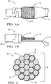
- Fig. 1A illustrates a non-limiting example of a top-view of the weld-joint 22 where the stranded-wire-core 12 is welded to the terminal 14.
- Fig. 1B illustrates a non-limiting example of a side-view of the weld-joint 22 of Fig. 1A where the stranded-wire-core 12 is welded to the terminal 14. Note that a cut-end 32 of the stranded-wire-core 12 is deformed due to the USW process, as will be recognized by one skilled in the art.
- Fig. 2 illustrates a non-limiting example of a cross-section 34 of the stranded-wire-core 12 containing the contaminant 18 on the surface 16 of the individual wire-strands 36.
- the contaminant 18 may be a vanishing oil or other organic compound that may be used as a lubricant during the wire manufacturing process.
- Fig. 3 illustrates a cleaning apparatus 38, such as a Soxhlet extractor 38A, that may be used to remove the contaminant 18 from the surface 16 of the wire-cable 10.
- a sample of the wire-cable 10 containing the contaminant 18 is weighed using a scale, after removing any insulation, to determine a combined-weight 40 ( Fig. 2 ) of the wire-cable 10 and the contaminant 18 prior to removing the contaminant 18 from the wire-cable 10.
- the sample of the wire-cable 10 may be placed inside the cleaning apparatus 38 and the sample is rinsed by a solvent 42 that is heating to a boiling-point 44 of the solvent 42 causing the solvent 42 to reflux, as will be recognized by one skilled in the art.
- the solvent 42 used in the cleaning apparatus 38 may be any solvent 42 compatible with the materials of the wire-cable 10 and may include diethyl ether 46, trichloromethane 48, and 2-propanone 50. Other solvents 42 that may be used are envisioned, but not listed.
- the solvent 42 is removed from the surface 16 of the wire-cable 10 by placing the wire-cable 10 in a desiccator-device 52, such as a desiccator that contains a desiccant, as will be recognized by one skilled in the art.
- a desiccator-device 52 such as a desiccator that contains a desiccant
- the wire-cable 10 should remain in the desiccator-device 52 for a minimum of twelve-hours (12-hours) at a temperature of between 15°C and 30°C and at a pressure of between 50 kilopascal (kPa) and 150 kPa.
- the wire-cable 10 is then weighed using the scale to determine a weight 54 of the wire-cable 10 without the contaminant 18, as illustrated in Fig. 4 .
- a percentage-by-weight 56 of the contaminant 18 removed from the wire-cable 10 may be determined based on a formula [(Mb-Ma)/Mb]*100, where Mb is defined as the combined-weight 40 of the wire-cable 10 and the contaminant 18 ( Fig. 2 ), and Ma is defined as the weight 54 of the wire-cable 10 with the contaminant 18 removed ( Fig. 4 ).
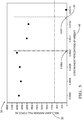
- Fig. 5 is a graph 58 that illustrates a relationship between the percentage-by-weight 56 of the contaminant 18 removed from the wire-cable 10 and the strength 20 of the weld-joint 22.
- the strength 20 of the weld-joint 22 may be characterized by a pull-force.
- the pull-force is defined as the tensile-force required to separate the bond between the wire-cable 10 and the terminal 14.
- Fig. 5 also illustrates the threshold 24 of the percentage-by-weight 56 of the contaminant 18 removed from the wire-cable 10, below which is determined to provide a weld-joint 22 of sufficient strength 20 to be applicable for automotive applications.
- the threshold 24 is set sufficiently low to provide for a controllable USW process.
- a threshold 24 of less than 0.021% may be indicative of a durable weld-joint 22.
- the threshold 24 may be further reduced to less than 0.0055% to further increase the strength 20 of the weld-joint 22, as also indicated in Fig. 5 .
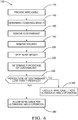
- Fig. 6 illustrates a non-limiting example of a method 100 used to predict the strength 20 of the ultrasonic weld-joint 22 of the wire-cable 10.
- Step 120 may include the step of providing the sample of the wire-cable 10 containing the organic contaminant 18.
- a length of wire-cable 10 is cut from a spool and any insulation is removed from the wire-cable 10 prior to placing the sample on the scale.
- the length of wire-cable 10 with a corresponding mass of between 50 grams (50 g) to 310 g provides a detectable amount of the contaminant 18.
- Step 140 DETERMINE COMBINED-WEIGHT
- Step 140 may include the step of determining the combined-weight 40 of the sample of wire-cable 10 and the contaminant 18 by weighing the sample using the scale.
- Any scale, and preferably an analytical balance, with a capacity sufficient for the mass of the sample and a resolution of 0.1 milligrams (0.1 mg) may be used, such as the Model AS 310.R2 Manufactured by RADWAG Balances and Scales of Radom, Poland.
- Step 160 REMOVE CONTAMINANT, may include the step of removing the contaminant 18 from the surface 16 of the wire-cable 10 using the solvent 42.
- Step 180 REMOVE SOLVENT, may include the step of removing the solvent 42 from the surface 16 of the wire-cable 10.
- Step 200 DETERMINE WEIGHT, may include the step of determining the weight 54 of the wire-cable 10 with the contaminant 18 removed and the solvent 42 removed.
- Step 220 DETERMINE PERCENTAGE OF CONTAMINANT, may include the step of determining the percentage-by-weight 56 of the contaminant 18 removed from the wire-cable 10 based on the formula [(Mb-Ma)/Mb]*100, wherein Mb is the combined-weight 40 of the wire-cable 10 and the contaminant 18 and Ma is the weight 54 of the wire-cable 10.
- Step 240 DETERMINE IF PERCENTAGE OF CONTAMINANT LESS THAN THRESHOLD, may include the step of determining whether the percentage-by-weight 56 of the contaminant 18 is less than the predetermined threshold 24, wherein the threshold 24 correlates to the strength 20 of the ultrasonic weld-joint 22.
- Step 260 EXCLUDE WIRE-CABLE FROM ULTRASONIC WELD OPERATION, may include the step of excluding a batch of the wire-cable 10 from the USW process if the percentage-by-weight 56 of the contaminant 18 is not less than the predetermined threshold 24.
- Step 280 ALLOW WIRE-CABLE FOR ULTRASONIC WELD OPERATION, may include the step of allowing a batch of wire-cable 10 to the USW process if the percentage-by-weight 56 of the contaminant 18 is less than the predetermined threshold 24.
- a method 100 used to predict the strength 20 of the ultrasonic weld-joint 22 of a wire-cable 10 is provided.
- the percentage-by-weight 56 of the contaminant 18 on the wire-cable 10 that is ultrasonically welded has found that there is a correlation between the percentage-by-weight 56 of the contaminant 18 on the wire-cable 10 that is ultrasonically welded, and the strength 20 of the weld-joint 22.
- the level of the threshold 24 of the percentage-by-weight 56 of the contaminant 18 also impacts the stability of the USW process.
Landscapes
- Engineering & Computer Science (AREA)
- Physics & Mathematics (AREA)
- Life Sciences & Earth Sciences (AREA)
- General Physics & Mathematics (AREA)
- Health & Medical Sciences (AREA)
- Mechanical Engineering (AREA)
- General Health & Medical Sciences (AREA)
- Pathology (AREA)
- Analytical Chemistry (AREA)
- Biochemistry (AREA)
- Chemical & Material Sciences (AREA)
- Immunology (AREA)
- Manufacturing & Machinery (AREA)
- Mathematical Physics (AREA)
- Theoretical Computer Science (AREA)
- Quality & Reliability (AREA)
- Biomedical Technology (AREA)
- Molecular Biology (AREA)
- Investigating Or Analyzing Materials By The Use Of Ultrasonic Waves (AREA)
- Cleaning And De-Greasing Of Metallic Materials By Chemical Methods (AREA)
- Testing Of Devices, Machine Parts, Or Other Structures Thereof (AREA)
- Pressure Welding/Diffusion-Bonding (AREA)
Claims (10)
- Procédé (100) pour prédire une résistance (20) d'un joint de soudure par ultrasons (22) d'un câble de fils (10), comprenant les étapes consistant à :fournir un échantillon d'un câble de fils (10) contenant un contaminant organique (18) ;déterminer un poids combiné (40) du câble de fils (10) et du contaminant (18);supprimer le contaminant (18) depuis une surface (16) du câble de fils (10) en utilisant un solvant (42) ;supprimer le solvant (42) depuis la surface (16) du câble de fils (10) ;déterminer un poids (54) du câble de fils (10) ;déterminer un pourcentage pondéral (56) du contaminant (18) supprimé du câble de fils (10) en se basant sur une formule [(Mb-Ma)/Mb]*100, dans laquelle Mb est le poids combiné (40) du câble de fils (10) et du contaminant (18) et Ma est le poids (54) du câble de fils (10) ; etcaractérisé parl'étape consistant à déterminer si le pourcentage pondéral (54) du contaminant (18) est inférieur à un seuil prédéterminé (24), dans lequel ledit seuil (24) est en corrélation avec la résistance (20) du joint de soudure par ultrasons (22).
- Procédé (100) selon la revendication 1, dans lequel le câble de fils (10) est un coeur à fils en forme de brins (12).
- Procédé (100) selon l'une des revendications précédentes, dans lequel le câble de fils (10) est formé d'un matériau sélectionné parmi la liste comprenant des matériaux à base d'aluminium (26) et des matériaux à base de cuivre (28).
- Procédé (100) selon l'une des revendications précédentes, dans lequel le câble de fils (10) est plaqué avec de l'étain (30).
- Procédé (100) selon l'une des revendications précédentes, dans lequel le solvant (42) est sélectionné parmi la liste comprenant du diéthyl éther (46), du trichlorométhane (48) et du 2-propanone (50).
- Procédé (100) selon l'une des revendications précédentes, comprenant en outre l'étape consistant à chauffer le solvant (42) jusqu'à un point d'ébullition (44).
- Procédé (100) selon l'une des revendications précédentes, comprenant en outre les étapes consistant à :placer l'échantillon à l'intérieur d'un extracteur de Soxhlet (38A) ; etrincer l'échantillon avec le solvant (42) à l'intérieur de l'extracteur de Soxhlet (38A).
- Procédé (100) selon l'une des revendications précédentes, dans lequel l'étape consistant à supprimer le solvant (42) depuis la surface (16) du câble de fils (10) est exécutée en utilisant un dispositif dessicateur (52).
- Procédé (100) selon l'une des revendications précédentes, dans lequel le câble de fils (10) est maintenu dans le dispositif dessicateur (52) pendant plus de 12 heures.
- Procédé (100) selon l'une des revendications précédentes, dans lequel ledit seuil (24) est un pourcentage pondéral de 0,021 (56).
Priority Applications (5)
| Application Number | Priority Date | Filing Date | Title |
|---|---|---|---|
| EP16204392.1A EP3336859B1 (fr) | 2016-12-15 | 2016-12-15 | Procédé pour prédire une résistance d'un joint de soudure ultrasonique |
| US15/698,907 US10569367B2 (en) | 2016-12-15 | 2017-09-08 | Method to predict a strength of an ultrasonic weld-joint |
| CN201711305186.1A CN108233143B (zh) | 2016-12-15 | 2017-12-11 | 用于预测超声波焊接接头的强度的方法 |
| KR1020170169922A KR102370199B1 (ko) | 2016-12-15 | 2017-12-12 | 초음파 용접-조인트의 강도를 예측하는 방법 |
| JP2017239683A JP7438652B2 (ja) | 2016-12-15 | 2017-12-14 | 超音波溶接継手の強度を予測するための方法 |
Applications Claiming Priority (1)
| Application Number | Priority Date | Filing Date | Title |
|---|---|---|---|
| EP16204392.1A EP3336859B1 (fr) | 2016-12-15 | 2016-12-15 | Procédé pour prédire une résistance d'un joint de soudure ultrasonique |
Publications (2)
| Publication Number | Publication Date |
|---|---|
| EP3336859A1 EP3336859A1 (fr) | 2018-06-20 |
| EP3336859B1 true EP3336859B1 (fr) | 2019-10-09 |
Family
ID=57681287
Family Applications (1)
| Application Number | Title | Priority Date | Filing Date |
|---|---|---|---|
| EP16204392.1A Active EP3336859B1 (fr) | 2016-12-15 | 2016-12-15 | Procédé pour prédire une résistance d'un joint de soudure ultrasonique |
Country Status (5)
| Country | Link |
|---|---|
| US (1) | US10569367B2 (fr) |
| EP (1) | EP3336859B1 (fr) |
| JP (1) | JP7438652B2 (fr) |
| KR (1) | KR102370199B1 (fr) |
| CN (1) | CN108233143B (fr) |
Families Citing this family (2)
| Publication number | Priority date | Publication date | Assignee | Title |
|---|---|---|---|---|
| EP3335827B1 (fr) * | 2016-12-15 | 2019-10-09 | Aptiv Technologies Limited | Procédé pour prédire une résistance d'un joint de soudure ultrasonique |
| CN110785894B (zh) * | 2017-06-21 | 2020-12-29 | 古河电气工业株式会社 | 电线连接结构体 |
Family Cites Families (18)
| Publication number | Priority date | Publication date | Assignee | Title |
|---|---|---|---|---|
| US3192474A (en) * | 1961-03-30 | 1965-06-29 | Texas Instruments Inc | Method and apparatus for determining the quality of a weld or solder joint by measurement of the dynamic resistance of the joint |
| US3916304A (en) * | 1974-01-17 | 1975-10-28 | Univ Akron | Method for nondestructive testing of weld clusters |
| US4503392A (en) * | 1981-07-21 | 1985-03-05 | Rizhsky Politekhnichesky Institut | Apparatus for non-destructive testing of spot welds using an electromagnetic field |
| US5412997A (en) * | 1992-12-11 | 1995-05-09 | Industrial Technology Research Institute | Nondestructive testing apparatus and method |
| CA2119061C (fr) * | 1994-03-15 | 1999-06-01 | Frederick H.G. Simmons | Methode et appareil pour essai de soudure |
| US5415047A (en) * | 1994-06-09 | 1995-05-16 | The United States Of America As Represented By The Secretary Of The Navy | Diffusion weld test fixture |
| US6393924B1 (en) * | 1997-11-10 | 2002-05-28 | Schunk Ultraschalltechnik Gmbh | Testing method for non-destructive testing of a welded connector, a testing device and an ultrasonic welding apparatus having such a device |
| JP4064828B2 (ja) * | 2003-01-15 | 2008-03-19 | 矢崎総業株式会社 | 溶接部の評価方法 |
| DE102009059307A1 (de) * | 2009-12-23 | 2011-06-30 | Schunk Sonosystems GmbH, 35435 | Verfahren zum elektrisch leitenden Verbinden von Drähten |
| JP5680379B2 (ja) * | 2010-11-12 | 2015-03-04 | 大京化学株式会社 | ポリエステル系繊維ニット用精練剤組成物とこれを用いる精練方法 |
| US8549928B2 (en) * | 2011-09-07 | 2013-10-08 | Schlumberger Technology Corporation | Weld strength test |
| JP2014032819A (ja) * | 2012-08-02 | 2014-02-20 | Swcc Showa Cable Systems Co Ltd | アルミ電線 |
| CN203179923U (zh) * | 2013-04-10 | 2013-09-04 | 海南英利新能源有限公司 | 粘接强度检测装置 |
| US20140374466A1 (en) * | 2013-06-19 | 2014-12-25 | Branson Ultrasonics Corporation | Method of ultrasonically welding multi-stranded malleable wires together |
| CN205081263U (zh) * | 2015-11-19 | 2016-03-09 | 黄胜正 | 接线端子快速测试接头 |
| CN105842030A (zh) * | 2016-04-13 | 2016-08-10 | 远东电缆有限公司 | 一种导线拉断力测试方法 |
| EP3335827B1 (fr) * | 2016-12-15 | 2019-10-09 | Aptiv Technologies Limited | Procédé pour prédire une résistance d'un joint de soudure ultrasonique |
| US20190271669A1 (en) * | 2018-03-01 | 2019-09-05 | Battelle Memorial Institute | Characterization of ultrasonic consolidation bond quality |
-
2016
- 2016-12-15 EP EP16204392.1A patent/EP3336859B1/fr active Active
-
2017
- 2017-09-08 US US15/698,907 patent/US10569367B2/en active Active
- 2017-12-11 CN CN201711305186.1A patent/CN108233143B/zh active Active
- 2017-12-12 KR KR1020170169922A patent/KR102370199B1/ko active Active
- 2017-12-14 JP JP2017239683A patent/JP7438652B2/ja active Active
Non-Patent Citations (1)
| Title |
|---|
| None * |
Also Published As
| Publication number | Publication date |
|---|---|
| US10569367B2 (en) | 2020-02-25 |
| KR102370199B1 (ko) | 2022-03-04 |
| CN108233143A (zh) | 2018-06-29 |
| US20180169795A1 (en) | 2018-06-21 |
| CN108233143B (zh) | 2019-07-05 |
| KR20180069711A (ko) | 2018-06-25 |
| EP3336859A1 (fr) | 2018-06-20 |
| JP2018111131A (ja) | 2018-07-19 |
| JP7438652B2 (ja) | 2024-02-27 |
Similar Documents
| Publication | Publication Date | Title |
|---|---|---|
| US10569367B2 (en) | Method to predict a strength of an ultrasonic weld-joint | |
| KR101526313B1 (ko) | 피로수명 예측방법 | |
| US10578534B2 (en) | Method to predict a strength of an ultrasonic weld-joint | |
| JP2010223945A (ja) | 材料への水素チャージ方法および材料の水素脆化特性の評価方法 | |
| Kumbár et al. | Oils degradation in agricultural machinery | |
| JP7388201B2 (ja) | 応力評価方法、曲げ加工性評価方法、および金属部材の製造方法 | |
| JP5356164B2 (ja) | 亀裂発生寿命予測装置および亀裂発生寿命予測方法 | |
| Lall et al. | Prognostication of copper-aluminum wirebond reliability under high temperature storage and temperature-humidity | |
| US7658538B2 (en) | Method for evaluating solder joint portion | |
| Kang et al. | Evaluation of the characteristics of 305SAC lead-free solder joints between a chip electrode and a Cu-pad in automotive electronics | |
| JP4669424B2 (ja) | 接合評価方法及びその装置 | |
| Lis et al. | Finite element-assisted assessment of the thermo-cyclic characteristics of leads soldered with SnAgCu (+ Bi, In) alloys | |
| JP4168090B2 (ja) | はんだ接合部の疲労評価方法 | |
| George et al. | Study on the interdependence of soldering profile, ageing conditions and intermetallic layer thickness in large area solder joints and its influence on reliability | |
| WO2024135188A1 (fr) | Procédé d'évaluation et dispositif d'évaluation de fragilisation par l'hydrogène | |
| KR101456868B1 (ko) | 냉간 가공된 금속의 충격인성에너지 예측방법 | |
| JP2011169635A (ja) | クリープ特性評価方法 | |
| JP5867191B2 (ja) | コネクタ端子用ばね材料の評価方法 | |
| Ilca et al. | Determination of proper parameters for ultrasonic welding of copper plate with copper wire strands | |
| RU2506564C1 (ru) | Способ оценки стойкости сварных изделий из низкоуглеродистых сталей к коррозионному растрескиванию под напряжением | |
| Llorente | New concept for the ground connection in scania’s trucks and buses | |
| Gorji et al. | Experimental based crack failure criterion and its application in deep drawing operations | |
| JP4443346B2 (ja) | 電子部品の試験評価方法、及び電子部品の試験評価装置 | |
| Lall et al. | Prognostic indicators for Cu-Al wirebond degradation under operation at elevated temperature and combined temperature humidity | |
| Lall et al. | High Temperature Storage and HAST Reliability of Copper-Aluminum Wirebond Interconnects |
Legal Events
| Date | Code | Title | Description |
|---|---|---|---|
| PUAI | Public reference made under article 153(3) epc to a published international application that has entered the european phase |
Free format text: ORIGINAL CODE: 0009012 |
|
| STAA | Information on the status of an ep patent application or granted ep patent |
Free format text: STATUS: THE APPLICATION HAS BEEN PUBLISHED |
|
| AK | Designated contracting states |
Kind code of ref document: A1 Designated state(s): AL AT BE BG CH CY CZ DE DK EE ES FI FR GB GR HR HU IE IS IT LI LT LU LV MC MK MT NL NO PL PT RO RS SE SI SK SM TR |
|
| AX | Request for extension of the european patent |
Extension state: BA ME |
|
| RAP1 | Party data changed (applicant data changed or rights of an application transferred) |
Owner name: APTIV TECHNOLOGIES LIMITED |
|
| STAA | Information on the status of an ep patent application or granted ep patent |
Free format text: STATUS: REQUEST FOR EXAMINATION WAS MADE |
|
| 17P | Request for examination filed |
Effective date: 20181220 |
|
| RBV | Designated contracting states (corrected) |
Designated state(s): AL AT BE BG CH CY CZ DE DK EE ES FI FR GB GR HR HU IE IS IT LI LT LU LV MC MK MT NL NO PL PT RO RS SE SI SK SM TR |
|
| RIC1 | Information provided on ipc code assigned before grant |
Ipc: B23K 31/12 20060101ALI20190306BHEP Ipc: H01B 13/00 20060101AFI20190306BHEP Ipc: G01G 19/414 20060101ALI20190306BHEP Ipc: B23K 20/10 20060101ALI20190306BHEP Ipc: G01N 5/04 20060101ALI20190306BHEP Ipc: B23K 101/38 20060101ALI20190306BHEP Ipc: H01R 43/02 20060101ALI20190306BHEP Ipc: G01N 1/40 20060101ALI20190306BHEP Ipc: G01N 33/20 20190101ALI20190306BHEP Ipc: B23K 101/32 20060101ALI20190306BHEP |
|
| GRAP | Despatch of communication of intention to grant a patent |
Free format text: ORIGINAL CODE: EPIDOSNIGR1 |
|
| STAA | Information on the status of an ep patent application or granted ep patent |
Free format text: STATUS: GRANT OF PATENT IS INTENDED |
|
| INTG | Intention to grant announced |
Effective date: 20190424 |
|
| GRAS | Grant fee paid |
Free format text: ORIGINAL CODE: EPIDOSNIGR3 |
|
| GRAA | (expected) grant |
Free format text: ORIGINAL CODE: 0009210 |
|
| STAA | Information on the status of an ep patent application or granted ep patent |
Free format text: STATUS: THE PATENT HAS BEEN GRANTED |
|
| AK | Designated contracting states |
Kind code of ref document: B1 Designated state(s): AL AT BE BG CH CY CZ DE DK EE ES FI FR GB GR HR HU IE IS IT LI LT LU LV MC MK MT NL NO PL PT RO RS SE SI SK SM TR |
|
| REG | Reference to a national code |
Ref country code: GB Ref legal event code: FG4D |
|
| REG | Reference to a national code |
Ref country code: CH Ref legal event code: EP |
|
| REG | Reference to a national code |
Ref country code: IE Ref legal event code: FG4D |
|
| REG | Reference to a national code |
Ref country code: DE Ref legal event code: R096 Ref document number: 602016022039 Country of ref document: DE |
|
| REG | Reference to a national code |
Ref country code: AT Ref legal event code: REF Ref document number: 1189767 Country of ref document: AT Kind code of ref document: T Effective date: 20191115 |
|
| REG | Reference to a national code |
Ref country code: NL Ref legal event code: MP Effective date: 20191009 |
|
| REG | Reference to a national code |
Ref country code: LT Ref legal event code: MG4D |
|
| REG | Reference to a national code |
Ref country code: AT Ref legal event code: MK05 Ref document number: 1189767 Country of ref document: AT Kind code of ref document: T Effective date: 20191009 |
|
| PG25 | Lapsed in a contracting state [announced via postgrant information from national office to epo] |
Ref country code: FI Free format text: LAPSE BECAUSE OF FAILURE TO SUBMIT A TRANSLATION OF THE DESCRIPTION OR TO PAY THE FEE WITHIN THE PRESCRIBED TIME-LIMIT Effective date: 20191009 Ref country code: NO Free format text: LAPSE BECAUSE OF FAILURE TO SUBMIT A TRANSLATION OF THE DESCRIPTION OR TO PAY THE FEE WITHIN THE PRESCRIBED TIME-LIMIT Effective date: 20200109 Ref country code: BG Free format text: LAPSE BECAUSE OF FAILURE TO SUBMIT A TRANSLATION OF THE DESCRIPTION OR TO PAY THE FEE WITHIN THE PRESCRIBED TIME-LIMIT Effective date: 20200109 Ref country code: LT Free format text: LAPSE BECAUSE OF FAILURE TO SUBMIT A TRANSLATION OF THE DESCRIPTION OR TO PAY THE FEE WITHIN THE PRESCRIBED TIME-LIMIT Effective date: 20191009 Ref country code: PL Free format text: LAPSE BECAUSE OF FAILURE TO SUBMIT A TRANSLATION OF THE DESCRIPTION OR TO PAY THE FEE WITHIN THE PRESCRIBED TIME-LIMIT Effective date: 20191009 Ref country code: LV Free format text: LAPSE BECAUSE OF FAILURE TO SUBMIT A TRANSLATION OF THE DESCRIPTION OR TO PAY THE FEE WITHIN THE PRESCRIBED TIME-LIMIT Effective date: 20191009 Ref country code: SE Free format text: LAPSE BECAUSE OF FAILURE TO SUBMIT A TRANSLATION OF THE DESCRIPTION OR TO PAY THE FEE WITHIN THE PRESCRIBED TIME-LIMIT Effective date: 20191009 Ref country code: ES Free format text: LAPSE BECAUSE OF FAILURE TO SUBMIT A TRANSLATION OF THE DESCRIPTION OR TO PAY THE FEE WITHIN THE PRESCRIBED TIME-LIMIT Effective date: 20191009 Ref country code: PT Free format text: LAPSE BECAUSE OF FAILURE TO SUBMIT A TRANSLATION OF THE DESCRIPTION OR TO PAY THE FEE WITHIN THE PRESCRIBED TIME-LIMIT Effective date: 20200210 Ref country code: GR Free format text: LAPSE BECAUSE OF FAILURE TO SUBMIT A TRANSLATION OF THE DESCRIPTION OR TO PAY THE FEE WITHIN THE PRESCRIBED TIME-LIMIT Effective date: 20200110 Ref country code: NL Free format text: LAPSE BECAUSE OF FAILURE TO SUBMIT A TRANSLATION OF THE DESCRIPTION OR TO PAY THE FEE WITHIN THE PRESCRIBED TIME-LIMIT Effective date: 20191009 Ref country code: AT Free format text: LAPSE BECAUSE OF FAILURE TO SUBMIT A TRANSLATION OF THE DESCRIPTION OR TO PAY THE FEE WITHIN THE PRESCRIBED TIME-LIMIT Effective date: 20191009 |
|
| PG25 | Lapsed in a contracting state [announced via postgrant information from national office to epo] |
Ref country code: IS Free format text: LAPSE BECAUSE OF FAILURE TO SUBMIT A TRANSLATION OF THE DESCRIPTION OR TO PAY THE FEE WITHIN THE PRESCRIBED TIME-LIMIT Effective date: 20200224 Ref country code: HR Free format text: LAPSE BECAUSE OF FAILURE TO SUBMIT A TRANSLATION OF THE DESCRIPTION OR TO PAY THE FEE WITHIN THE PRESCRIBED TIME-LIMIT Effective date: 20191009 Ref country code: RS Free format text: LAPSE BECAUSE OF FAILURE TO SUBMIT A TRANSLATION OF THE DESCRIPTION OR TO PAY THE FEE WITHIN THE PRESCRIBED TIME-LIMIT Effective date: 20191009 |
|
| PG25 | Lapsed in a contracting state [announced via postgrant information from national office to epo] |
Ref country code: AL Free format text: LAPSE BECAUSE OF FAILURE TO SUBMIT A TRANSLATION OF THE DESCRIPTION OR TO PAY THE FEE WITHIN THE PRESCRIBED TIME-LIMIT Effective date: 20191009 |
|
| REG | Reference to a national code |
Ref country code: DE Ref legal event code: R097 Ref document number: 602016022039 Country of ref document: DE |
|
| PG2D | Information on lapse in contracting state deleted |
Ref country code: IS |
|
| PG25 | Lapsed in a contracting state [announced via postgrant information from national office to epo] |
Ref country code: CZ Free format text: LAPSE BECAUSE OF FAILURE TO SUBMIT A TRANSLATION OF THE DESCRIPTION OR TO PAY THE FEE WITHIN THE PRESCRIBED TIME-LIMIT Effective date: 20191009 Ref country code: DK Free format text: LAPSE BECAUSE OF FAILURE TO SUBMIT A TRANSLATION OF THE DESCRIPTION OR TO PAY THE FEE WITHIN THE PRESCRIBED TIME-LIMIT Effective date: 20191009 Ref country code: EE Free format text: LAPSE BECAUSE OF FAILURE TO SUBMIT A TRANSLATION OF THE DESCRIPTION OR TO PAY THE FEE WITHIN THE PRESCRIBED TIME-LIMIT Effective date: 20191009 Ref country code: RO Free format text: LAPSE BECAUSE OF FAILURE TO SUBMIT A TRANSLATION OF THE DESCRIPTION OR TO PAY THE FEE WITHIN THE PRESCRIBED TIME-LIMIT Effective date: 20191009 Ref country code: IS Free format text: LAPSE BECAUSE OF FAILURE TO SUBMIT A TRANSLATION OF THE DESCRIPTION OR TO PAY THE FEE WITHIN THE PRESCRIBED TIME-LIMIT Effective date: 20200209 |
|
| REG | Reference to a national code |
Ref country code: CH Ref legal event code: PL |
|
| PLBE | No opposition filed within time limit |
Free format text: ORIGINAL CODE: 0009261 |
|
| STAA | Information on the status of an ep patent application or granted ep patent |
Free format text: STATUS: NO OPPOSITION FILED WITHIN TIME LIMIT |
|
| REG | Reference to a national code |
Ref country code: BE Ref legal event code: MM Effective date: 20191231 |
|
| PG25 | Lapsed in a contracting state [announced via postgrant information from national office to epo] |
Ref country code: MC Free format text: LAPSE BECAUSE OF FAILURE TO SUBMIT A TRANSLATION OF THE DESCRIPTION OR TO PAY THE FEE WITHIN THE PRESCRIBED TIME-LIMIT Effective date: 20191009 Ref country code: IT Free format text: LAPSE BECAUSE OF FAILURE TO SUBMIT A TRANSLATION OF THE DESCRIPTION OR TO PAY THE FEE WITHIN THE PRESCRIBED TIME-LIMIT Effective date: 20191009 Ref country code: SM Free format text: LAPSE BECAUSE OF FAILURE TO SUBMIT A TRANSLATION OF THE DESCRIPTION OR TO PAY THE FEE WITHIN THE PRESCRIBED TIME-LIMIT Effective date: 20191009 Ref country code: SK Free format text: LAPSE BECAUSE OF FAILURE TO SUBMIT A TRANSLATION OF THE DESCRIPTION OR TO PAY THE FEE WITHIN THE PRESCRIBED TIME-LIMIT Effective date: 20191009 |
|
| 26N | No opposition filed |
Effective date: 20200710 |
|
| PG25 | Lapsed in a contracting state [announced via postgrant information from national office to epo] |
Ref country code: LU Free format text: LAPSE BECAUSE OF NON-PAYMENT OF DUE FEES Effective date: 20191215 Ref country code: IE Free format text: LAPSE BECAUSE OF NON-PAYMENT OF DUE FEES Effective date: 20191215 |
|
| PG25 | Lapsed in a contracting state [announced via postgrant information from national office to epo] |
Ref country code: BE Free format text: LAPSE BECAUSE OF NON-PAYMENT OF DUE FEES Effective date: 20191231 Ref country code: SI Free format text: LAPSE BECAUSE OF FAILURE TO SUBMIT A TRANSLATION OF THE DESCRIPTION OR TO PAY THE FEE WITHIN THE PRESCRIBED TIME-LIMIT Effective date: 20191009 Ref country code: CH Free format text: LAPSE BECAUSE OF NON-PAYMENT OF DUE FEES Effective date: 20191231 Ref country code: LI Free format text: LAPSE BECAUSE OF NON-PAYMENT OF DUE FEES Effective date: 20191231 |
|
| PG25 | Lapsed in a contracting state [announced via postgrant information from national office to epo] |
Ref country code: CY Free format text: LAPSE BECAUSE OF FAILURE TO SUBMIT A TRANSLATION OF THE DESCRIPTION OR TO PAY THE FEE WITHIN THE PRESCRIBED TIME-LIMIT Effective date: 20191009 |
|
| PG25 | Lapsed in a contracting state [announced via postgrant information from national office to epo] |
Ref country code: HU Free format text: LAPSE BECAUSE OF FAILURE TO SUBMIT A TRANSLATION OF THE DESCRIPTION OR TO PAY THE FEE WITHIN THE PRESCRIBED TIME-LIMIT; INVALID AB INITIO Effective date: 20161215 Ref country code: MT Free format text: LAPSE BECAUSE OF FAILURE TO SUBMIT A TRANSLATION OF THE DESCRIPTION OR TO PAY THE FEE WITHIN THE PRESCRIBED TIME-LIMIT Effective date: 20191009 |
|
| PG25 | Lapsed in a contracting state [announced via postgrant information from national office to epo] |
Ref country code: TR Free format text: LAPSE BECAUSE OF FAILURE TO SUBMIT A TRANSLATION OF THE DESCRIPTION OR TO PAY THE FEE WITHIN THE PRESCRIBED TIME-LIMIT Effective date: 20191009 |
|
| PG25 | Lapsed in a contracting state [announced via postgrant information from national office to epo] |
Ref country code: MK Free format text: LAPSE BECAUSE OF FAILURE TO SUBMIT A TRANSLATION OF THE DESCRIPTION OR TO PAY THE FEE WITHIN THE PRESCRIBED TIME-LIMIT Effective date: 20191009 |
|
| P01 | Opt-out of the competence of the unified patent court (upc) registered |
Effective date: 20230424 |
|
| REG | Reference to a national code |
Ref country code: DE Ref legal event code: R081 Ref document number: 602016022039 Country of ref document: DE Owner name: APTIV TECHNOLOGIES AG, CH Free format text: FORMER OWNER: APTIV TECHNOLOGIES LIMITED, ST. MICHAEL, BB |
|
| PGFP | Annual fee paid to national office [announced via postgrant information from national office to epo] |
Ref country code: DE Payment date: 20251117 Year of fee payment: 10 |
|
| PGFP | Annual fee paid to national office [announced via postgrant information from national office to epo] |
Ref country code: GB Payment date: 20251107 Year of fee payment: 10 |
|
| PGFP | Annual fee paid to national office [announced via postgrant information from national office to epo] |
Ref country code: FR Payment date: 20251112 Year of fee payment: 10 |