EP3336868A1 - Schaltgerät - Google Patents
Schaltgerät Download PDFInfo
- Publication number
- EP3336868A1 EP3336868A1 EP16204367.3A EP16204367A EP3336868A1 EP 3336868 A1 EP3336868 A1 EP 3336868A1 EP 16204367 A EP16204367 A EP 16204367A EP 3336868 A1 EP3336868 A1 EP 3336868A1
- Authority
- EP
- European Patent Office
- Prior art keywords
- current
- gas tube
- switching apparatus
- electrical connection
- terminals
- Prior art date
- Legal status (The legal status is an assumption and is not a legal conclusion. Google has not performed a legal analysis and makes no representation as to the accuracy of the status listed.)
- Granted
Links
Images
Classifications
-
- H—ELECTRICITY
- H01—ELECTRIC ELEMENTS
- H01H—ELECTRIC SWITCHES; RELAYS; SELECTORS; EMERGENCY PROTECTIVE DEVICES
- H01H9/00—Details of switching devices, not covered by groups H01H1/00 - H01H7/00
- H01H9/30—Means for extinguishing or preventing arc between current-carrying parts
- H01H9/40—Multiple main contacts for the purpose of dividing the current through, or potential drop along, the arc
-
- H—ELECTRICITY
- H01—ELECTRIC ELEMENTS
- H01H—ELECTRIC SWITCHES; RELAYS; SELECTORS; EMERGENCY PROTECTIVE DEVICES
- H01H33/00—High-tension or heavy-current switches with arc-extinguishing or arc-preventing means
- H01H33/02—Details
- H01H33/59—Circuit arrangements not adapted to a particular application of the switch and not otherwise provided for, e.g. for ensuring operation of the switch at a predetermined point in the AC cycle
- H01H33/596—Circuit arrangements not adapted to a particular application of the switch and not otherwise provided for, e.g. for ensuring operation of the switch at a predetermined point in the AC cycle for interrupting DC
-
- Y—GENERAL TAGGING OF NEW TECHNOLOGICAL DEVELOPMENTS; GENERAL TAGGING OF CROSS-SECTIONAL TECHNOLOGIES SPANNING OVER SEVERAL SECTIONS OF THE IPC; TECHNICAL SUBJECTS COVERED BY FORMER USPC CROSS-REFERENCE ART COLLECTIONS [XRACs] AND DIGESTS
- Y02—TECHNOLOGIES OR APPLICATIONS FOR MITIGATION OR ADAPTATION AGAINST CLIMATE CHANGE
- Y02E—REDUCTION OF GREENHOUSE GAS [GHG] EMISSIONS, RELATED TO ENERGY GENERATION, TRANSMISSION OR DISTRIBUTION
- Y02E60/00—Enabling technologies; Technologies with a potential or indirect contribution to GHG emissions mitigation
- Y02E60/60—Arrangements for transfer of electric power between AC networks or generators via a high voltage DC link [HVCD]
Definitions
- This invention relates to a switching apparatus, preferably for use in high voltage direct current (HVDC) applications.
- HVDC high voltage direct current
- a switching apparatus comprising a plurality of current-conductive branches connected in parallel between first and second terminals, each current-conductive branch including at least one respective electrical connection member in series connection with at least one respective gas tube switch between the first and second terminals, wherein the inductance value of each electrical connection member is configured to balance the inductance values of the current-conductive branches.
- each current-conductive branch may include a single gas tube switch or a plurality of gas tube switches (e.g. a plurality of series-connected gas tube switches).
- each current-conductive branch may include a single electrical connection member or a plurality of electrical connection members (e.g. a plurality of series-connected electrical connection members).
- each electrical connection member may take the form of any type of electrically conductive component (e.g. an electrical lead or wiring) capable of connecting a gas tube switch to either of the first and second terminals.
- electrically conductive component e.g. an electrical lead or wiring
- the current rating of a given gas tube switch may be too low to meet the current rating requirements of the switching application.
- the parallel connection of the current-conductive branches in the switching apparatus of the invention provides a "gas tube switch"-based switching apparatus with a combined current rating that is higher than the current rating of the individual gas tube switch, and thereby enables the use of gas tube switches in switching applications with higher current rating requirements.
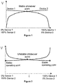
- the positive slope resistances of the power semiconductor switches are such that current sharing between the parallel-connected power semiconductor switches occurs naturally to a degree, especially if the temperature coefficient is positive.
- Figure 1 illustrates the stable current sharing between parallel-connected power semiconductor switches (which are referred to as Device 1 and Device 2 respectively), where there is a stable crossover point between their voltage-current characteristics.
- gate control can be employed to control the states of the parallel-connected power semiconductor switches in order to rebalance the currents flowing through the parallel-connected power semiconductor switches.
- Configuring the inductance values of the electrical connection members to balance the inductance values of the current-conductive branches advantageously improves the sharing of current between the current-conductive branches based on gas tube switches, thus beneficially improving the reliability of the "gas tube switch"-based switching apparatus.
- the switching apparatus may vary in configuration in order to configure the inductance value of each electrical connection member so as to balance the inductance values of the current-conductive branches.
- At least one of the electrical connection members may be or may include a reactor, wherein the inductance value of the or each reactor is configured to balance the inductance values of the current-conductive branches.
- the or each reactor may be arranged as a coil, and the number of coil turns in the or each reactor may be defined to configure the inductance value of the or each reactor so as to balance the inductance values of the current-conductive branches.
- the number of coil turns in the or each reactor arranged as a coil may range from a single coil turn to a plurality of coil turns.
- the electrical connection members may be dimensioned to configure their respective inductance values so as to balance the inductance values of the current-conductive branches.
- the lengths of the electrical connection members may be dimensioned to configure their respective stray inductance values.
- the gas tube switches may be positioned relative to the terminals to simplify the configuration of the inductance value of each electrical connection member to balance the inductance values of the current-conductive branches.
- the gas tube switches may be positioned relative to the terminals to simplify the configuration of the inductance value of the or each reactor and/or the dimensioning of the electrical connection members required to configure the inductance value of each electrical connection member so as to balance the inductance values of the current-conductive branches.
- Such positioning of the gas tube switches may be carried out in a number of different ways, non-limiting examples of which are described as follows.
- the gas tube switches may be positioned in a symmetrical arrangement about a reference axis extending through the terminals.
- the gas tube switches may be positioned in a circular arrangement about a reference axis extending through the terminals.
- the gas tube switches may be positioned in a radial arrangement about a reference axis extending through the terminals.
- the gas tube switches may be arranged to be equidistant from a reference axis extending through the terminals.
- the gas tube switches may be arranged to be equidistant from the first terminal, and the gas tube switches are arranged to be equidistant from the second terminal.
- the switching apparatus of the invention may be used in a wide range of switching applications.
- the switching apparatus may be configured for use in a HVDC application.
- the number of current-conductive branches of the switching apparatus may be configured so that the switching apparatus has a current rating suitable for a HVDC application.
- the ability of the switching apparatus of the invention to control the distribution of current between the current-conductive branches improves the compatibility of gas tube switches with the high current rating requirements of HVDC applications.
- first and second in this patent specification is merely intended to help distinguish between similar features (e.g. the first and second terminals), and is not intended to indicate the relative importance of one feature over another feature, unless otherwise specified.
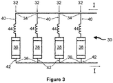
- a switching apparatus according to a first embodiment of the invention is shown in Figure 3 and is designated generally by the reference numeral 30.
- the switching apparatus 30 comprises a plurality of current-conductive branches 32 that are connected in parallel between first and second terminals 34,36.
- Each current-conductive branch 32 includes a respective gas tube switch 38.
- Each gas tube switch 38 includes a chamber enclosing an ionizable gas, and is configured to generate a plasma of ionized gas to facilitate a controlled current flow through the gas tube switch 38.
- there are four current-conductive branches 32 in the embodiment shown, there are four current-conductive branches 32, but it will be appreciated that the number of current-conductive branches 32 of the switching apparatus 30 may vary.
- Each current-conductive branch 32 includes a first electrical connection member 40 that connects an electrode of the gas tube switch 38 to the first terminal 34, and a second electrical connection member 42 that connects another electrode of the gas tube switch 38 to the second terminal 36.
- the first electrical connection member 40 includes electrically conductive wiring and a series reactor 44, while the second electrical connection member 42 includes electrically conductive wiring.
- Each series reactor 44 is arranged as a coil.
- the number of coil turns in each reactor 44 is defined to configure the inductance value of each reactor 44 so as to balance the inductance values of the current-conductive branches 32. More particularly, the number of coil turns in each reactor 44 is defined by taking into consideration the stray inductance present in the respective electrical connection member 40,42 so as to achieve a balance between the overall inductance values of the current-conductive branches 32.
- Configuring the inductance values of the reactors 44 to balance the inductance values of the current-conductive branches 32 advantageously improves the sharing of current I between the current-conductive branches 32 based on gas tube switches 38, thus beneficially improving the reliability of the "gas tube switch"-based switching apparatus 30.
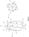
- a switching apparatus according to a second embodiment of the invention is shown in Figure 4 and is designated generally by the reference numeral 130.
- the switching apparatus 130 comprises a plurality of current-conductive branches 32 that are connected in parallel between first and second terminals 34,36.
- Each current-conductive branch 32 includes a respective gas tube switch 38.
- Each gas tube switch 38 includes a chamber enclosing an ionizable gas, and is configured to generate a plasma of ionized gas to facilitate a controlled current flow through the gas tube switch 38.
- there are four current-conductive branches 32 but it will be appreciated that the number of current-conductive branches 32 of the switching apparatus 130 may vary.
- Each current-conductive branch 32 includes a first electrical connection member 40 that connects an electrode of the gas tube switch 38 to the first terminal 34, and a second electrical connection member 42 that connects another electrode of the gas tube switch 38 to the second terminal 36.
- Each of the first and second electrical connection members 40,42 includes electrically conductive wiring.
- the gas tube switches 38 are positioned in a symmetrical, radial arrangement about a reference axis 46 extending through the terminals 34,36, such that the gas tube switches 38 are arranged to be equidistant from the reference axis 46, equidistant from the first terminal 34, and equidistant from the second terminal 36. Meanwhile the lengths of the electrical connection members 40,42 are dimensioned to configure their respective inductance values so as to balance the stray inductances present in the electrical connection members 40,42 and therefore balance the overall inductance values of the current-conductive branches 32.
- the above symmetrical, radial arrangement of the gas tube switches 38 makes it easier to define the lengths of the electrical connection members 40,42 to configure the inductance value of each electrical connection member 40,42 so as to balance the overall inductance values of the current-conductive branches 32, while at the same time providing a compact arrangement of the gas tube switches 38.
- Arranging the gas tube switches 38 in the above symmetrical, radial arrangement and dimensioning the electrical connection members 40,42 to balance the inductance values of the current-conductive branches 32 advantageously improves the sharing of current I between the current-conductive branches 32 based on gas tube switches 38, thus beneficially improving the reliability of the "gas tube switch"-based switching apparatus.
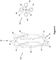
- a switching apparatus according to a third embodiment of the invention is shown in Figure 5 and is designated generally by the reference numeral 230.
- the switching apparatus 230 comprises a plurality of current-conductive branches 32 that are connected in parallel between first and second terminals 34,36.
- Each current-conductive branch 32 includes a respective gas tube switch 38.
- Each gas tube switch 38 includes a chamber enclosing an ionizable gas, and is configured to generate a plasma of ionized gas to facilitate a controlled current flow through the gas tube switch 38.
- there are eight current-conductive branches 32 in the embodiment shown, there are eight current-conductive branches 32, but it will be appreciated that the number of current-conductive branches 32 of the switching apparatus 230 may vary.
- Each current-conductive branch 32 includes a first electrical connection member 40 that connects an electrode of the gas tube switch 38 to the first terminal 34, and a second electrical connection member 42 that connects another electrode of the gas tube switch 38 to the second terminal 36.
- Each of the first and second electrical connection members 40,42 includes electrically conductive wiring.
- the gas tube switches 38 are positioned in a symmetrical, circular arrangement (and therefore also a radial arrangement) about a reference axis 46 extending through the terminals 34,36, such that the gas tube switches 38 are arranged to be equidistant from the reference axis 46, equidistant from the first terminal 34, and equidistant from the second terminal 36.
- the lengths of the electrical connection members 40,42 are dimensioned to configure their respective inductance values so as to balance the stray inductances present in the electrical connection members 40,42 and therefore balance the overall inductance values of the current-conductive branches 32.
- the above symmetrical, circular arrangement of the gas tube switches 38 makes it easier to define the lengths of the electrical connection members 40,42 to configure the inductance value of each electrical connection member 40,42 so as to balance the overall inductance values of the current-conductive branches 32, while at the same time providing a compact arrangement of the gas tube switches 38.
- Arranging the gas tube switches 38 in the above symmetrical, circular arrangement and dimensioning the electrical connection members 40,42 to balance the inductance values of the current-conductive branches 32 advantageously improves the sharing of current I between the current-conductive branches 32 based on gas tube switches 38, thus beneficially improving the reliability of the "gas tube switch"-based switching apparatus.
Landscapes
- Engineering & Computer Science (AREA)
- Power Engineering (AREA)
- Chemical Vapour Deposition (AREA)
- Gas-Filled Discharge Tubes (AREA)
- Gas-Insulated Switchgears (AREA)
- Physical Or Chemical Processes And Apparatus (AREA)
Priority Applications (4)
| Application Number | Priority Date | Filing Date | Title |
|---|---|---|---|
| EP16204367.3A EP3336868B1 (de) | 2016-12-15 | 2016-12-15 | Schaltgerät |
| PCT/EP2017/082131 WO2018108768A1 (en) | 2016-12-15 | 2017-12-11 | Switching apparatus |
| US16/470,043 US11387060B2 (en) | 2016-12-15 | 2017-12-11 | Switching apparatus |
| CN201780077493.0A CN110050318B (zh) | 2016-12-15 | 2017-12-11 | 开关设备 |
Applications Claiming Priority (1)
| Application Number | Priority Date | Filing Date | Title |
|---|---|---|---|
| EP16204367.3A EP3336868B1 (de) | 2016-12-15 | 2016-12-15 | Schaltgerät |
Publications (2)
| Publication Number | Publication Date |
|---|---|
| EP3336868A1 true EP3336868A1 (de) | 2018-06-20 |
| EP3336868B1 EP3336868B1 (de) | 2023-05-17 |
Family
ID=57749677
Family Applications (1)
| Application Number | Title | Priority Date | Filing Date |
|---|---|---|---|
| EP16204367.3A Active EP3336868B1 (de) | 2016-12-15 | 2016-12-15 | Schaltgerät |
Country Status (4)
| Country | Link |
|---|---|
| US (1) | US11387060B2 (de) |
| EP (1) | EP3336868B1 (de) |
| CN (1) | CN110050318B (de) |
| WO (1) | WO2018108768A1 (de) |
Families Citing this family (1)
| Publication number | Priority date | Publication date | Assignee | Title |
|---|---|---|---|---|
| EP3336872B1 (de) * | 2016-12-15 | 2019-10-23 | General Electric Technology GmbH | Schaltvorrichtung |
Citations (4)
| Publication number | Priority date | Publication date | Assignee | Title |
|---|---|---|---|---|
| FR1566251A (de) * | 1967-01-12 | 1969-05-09 | ||
| US4262215A (en) * | 1979-05-10 | 1981-04-14 | Tokyo Shibaura Denki Kabushiki Kaisha | Direct current interrupter |
| DE102008015437B3 (de) * | 2008-03-22 | 2009-07-30 | Moeller Gmbh | Symmetrierungsanordnung für parallele Strombahnen |
| WO2010060476A1 (en) * | 2008-11-26 | 2010-06-03 | Abb Technology Ag | High voltage direct current circuit breaker arrangement and method |
Family Cites Families (3)
| Publication number | Priority date | Publication date | Assignee | Title |
|---|---|---|---|---|
| JPH0950743A (ja) * | 1995-08-08 | 1997-02-18 | Mitsubishi Electric Corp | 直流遮断装置 |
| US7574312B2 (en) * | 2004-11-08 | 2009-08-11 | Panasonic Corporation | Semiconductor device and communications terminal and automobile having the same |
| US9748857B2 (en) * | 2015-08-12 | 2017-08-29 | General Electric Company | Method and system for a gas tube-based current source high voltage direct current transmission system |
-
2016
- 2016-12-15 EP EP16204367.3A patent/EP3336868B1/de active Active
-
2017
- 2017-12-11 WO PCT/EP2017/082131 patent/WO2018108768A1/en not_active Ceased
- 2017-12-11 CN CN201780077493.0A patent/CN110050318B/zh not_active Expired - Fee Related
- 2017-12-11 US US16/470,043 patent/US11387060B2/en active Active
Patent Citations (4)
| Publication number | Priority date | Publication date | Assignee | Title |
|---|---|---|---|---|
| FR1566251A (de) * | 1967-01-12 | 1969-05-09 | ||
| US4262215A (en) * | 1979-05-10 | 1981-04-14 | Tokyo Shibaura Denki Kabushiki Kaisha | Direct current interrupter |
| DE102008015437B3 (de) * | 2008-03-22 | 2009-07-30 | Moeller Gmbh | Symmetrierungsanordnung für parallele Strombahnen |
| WO2010060476A1 (en) * | 2008-11-26 | 2010-06-03 | Abb Technology Ag | High voltage direct current circuit breaker arrangement and method |
Also Published As
| Publication number | Publication date |
|---|---|
| US11387060B2 (en) | 2022-07-12 |
| CN110050318B (zh) | 2022-08-12 |
| EP3336868B1 (de) | 2023-05-17 |
| WO2018108768A1 (en) | 2018-06-21 |
| US20200013571A1 (en) | 2020-01-09 |
| CN110050318A (zh) | 2019-07-23 |
Similar Documents
| Publication | Publication Date | Title |
|---|---|---|
| US20170025866A1 (en) | Electrical energy storage system | |
| CN102947902B (zh) | 有载分接开关 | |
| CN104247251B (zh) | 调节变压器 | |
| KR20130063505A (ko) | 부하시 탭 전환기 | |
| US9287036B2 (en) | Supplementary transformer winding | |
| CN114127878A (zh) | 有载分接开关 | |
| CN103282986A (zh) | 具有真空开关管的分接开关 | |
| KR102014225B1 (ko) | 온-부하 탭-절환 장치가 있는 변압기 | |
| US10614974B2 (en) | Switching device | |
| US11373816B2 (en) | Circuit breaker | |
| JP2014504808A (ja) | タップ切換装置 | |
| RU2011145275A (ru) | Ступенчатый переключатель с полупроводниковыми переключательными элементами | |
| US11387060B2 (en) | Switching apparatus | |
| US20200013570A1 (en) | Switching apparatus | |
| US20130293010A1 (en) | Current supply arrangement with a first and a second current supply device, wherein the second current supply device is connected to the first current supply device | |
| CN105580099B (zh) | 分接开关、可调变压器和用于转换相应预选器的方法 | |
| EP3301695A1 (de) | Überbrückungsstreifen und umschaltvorrichtungsanordnung | |
| US11972915B2 (en) | Breaking device | |
| US20160248337A1 (en) | Power Conversion Apparatus | |
| EP2560274A2 (de) | Kondensatorschaltung mit temperaturveränderlicher Kapazität in einem Wandler und Lade-/Entladeverfahren | |
| US12170179B2 (en) | High-voltage circuit disconnection | |
| CN114758875A (zh) | 一种单相自耦变压器及调压方法 | |
| US20130027019A1 (en) | Power supply with means for increasing a voltage | |
| Ishikawa et al. | Dependence of current interruption performance on the element patterns of etched fuses | |
| Liu et al. | Switching strategy of electronic divider for hybrid on-load tap changers based on zero-crossing signal |
Legal Events
| Date | Code | Title | Description |
|---|---|---|---|
| PUAI | Public reference made under article 153(3) epc to a published international application that has entered the european phase |
Free format text: ORIGINAL CODE: 0009012 |
|
| STAA | Information on the status of an ep patent application or granted ep patent |
Free format text: STATUS: THE APPLICATION HAS BEEN PUBLISHED |
|
| AK | Designated contracting states |
Kind code of ref document: A1 Designated state(s): AL AT BE BG CH CY CZ DE DK EE ES FI FR GB GR HR HU IE IS IT LI LT LU LV MC MK MT NL NO PL PT RO RS SE SI SK SM TR |
|
| AX | Request for extension of the european patent |
Extension state: BA ME |
|
| STAA | Information on the status of an ep patent application or granted ep patent |
Free format text: STATUS: REQUEST FOR EXAMINATION WAS MADE |
|
| 17P | Request for examination filed |
Effective date: 20181220 |
|
| RBV | Designated contracting states (corrected) |
Designated state(s): AL AT BE BG CH CY CZ DE DK EE ES FI FR GB GR HR HU IE IS IT LI LT LU LV MC MK MT NL NO PL PT RO RS SE SI SK SM TR |
|
| STAA | Information on the status of an ep patent application or granted ep patent |
Free format text: STATUS: EXAMINATION IS IN PROGRESS |
|
| 17Q | First examination report despatched |
Effective date: 20200403 |
|
| GRAP | Despatch of communication of intention to grant a patent |
Free format text: ORIGINAL CODE: EPIDOSNIGR1 |
|
| STAA | Information on the status of an ep patent application or granted ep patent |
Free format text: STATUS: GRANT OF PATENT IS INTENDED |
|
| INTG | Intention to grant announced |
Effective date: 20221207 |
|
| GRAS | Grant fee paid |
Free format text: ORIGINAL CODE: EPIDOSNIGR3 |
|
| GRAA | (expected) grant |
Free format text: ORIGINAL CODE: 0009210 |
|
| STAA | Information on the status of an ep patent application or granted ep patent |
Free format text: STATUS: THE PATENT HAS BEEN GRANTED |
|
| AK | Designated contracting states |
Kind code of ref document: B1 Designated state(s): AL AT BE BG CH CY CZ DE DK EE ES FI FR GB GR HR HU IE IS IT LI LT LU LV MC MK MT NL NO PL PT RO RS SE SI SK SM TR |
|
| REG | Reference to a national code |
Ref country code: GB Ref legal event code: FG4D |
|
| REG | Reference to a national code |
Ref country code: CH Ref legal event code: EP |
|
| REG | Reference to a national code |
Ref country code: DE Ref legal event code: R096 Ref document number: 602016079469 Country of ref document: DE |
|
| REG | Reference to a national code |
Ref country code: IE Ref legal event code: FG4D |
|
| REG | Reference to a national code |
Ref country code: AT Ref legal event code: REF Ref document number: 1568751 Country of ref document: AT Kind code of ref document: T Effective date: 20230615 |
|
| REG | Reference to a national code |
Ref country code: SE Ref legal event code: TRGR |
|
| P01 | Opt-out of the competence of the unified patent court (upc) registered |
Effective date: 20230522 |
|
| REG | Reference to a national code |
Ref country code: LT Ref legal event code: MG9D |
|
| REG | Reference to a national code |
Ref country code: NL Ref legal event code: MP Effective date: 20230517 |
|
| REG | Reference to a national code |
Ref country code: AT Ref legal event code: MK05 Ref document number: 1568751 Country of ref document: AT Kind code of ref document: T Effective date: 20230517 |
|
| PG25 | Lapsed in a contracting state [announced via postgrant information from national office to epo] |
Ref country code: PT Free format text: LAPSE BECAUSE OF FAILURE TO SUBMIT A TRANSLATION OF THE DESCRIPTION OR TO PAY THE FEE WITHIN THE PRESCRIBED TIME-LIMIT Effective date: 20230918 Ref country code: NO Free format text: LAPSE BECAUSE OF FAILURE TO SUBMIT A TRANSLATION OF THE DESCRIPTION OR TO PAY THE FEE WITHIN THE PRESCRIBED TIME-LIMIT Effective date: 20230817 Ref country code: NL Free format text: LAPSE BECAUSE OF FAILURE TO SUBMIT A TRANSLATION OF THE DESCRIPTION OR TO PAY THE FEE WITHIN THE PRESCRIBED TIME-LIMIT Effective date: 20230517 Ref country code: ES Free format text: LAPSE BECAUSE OF FAILURE TO SUBMIT A TRANSLATION OF THE DESCRIPTION OR TO PAY THE FEE WITHIN THE PRESCRIBED TIME-LIMIT Effective date: 20230517 Ref country code: AT Free format text: LAPSE BECAUSE OF FAILURE TO SUBMIT A TRANSLATION OF THE DESCRIPTION OR TO PAY THE FEE WITHIN THE PRESCRIBED TIME-LIMIT Effective date: 20230517 |
|
| PG25 | Lapsed in a contracting state [announced via postgrant information from national office to epo] |
Ref country code: RS Free format text: LAPSE BECAUSE OF FAILURE TO SUBMIT A TRANSLATION OF THE DESCRIPTION OR TO PAY THE FEE WITHIN THE PRESCRIBED TIME-LIMIT Effective date: 20230517 Ref country code: PL Free format text: LAPSE BECAUSE OF FAILURE TO SUBMIT A TRANSLATION OF THE DESCRIPTION OR TO PAY THE FEE WITHIN THE PRESCRIBED TIME-LIMIT Effective date: 20230517 Ref country code: LV Free format text: LAPSE BECAUSE OF FAILURE TO SUBMIT A TRANSLATION OF THE DESCRIPTION OR TO PAY THE FEE WITHIN THE PRESCRIBED TIME-LIMIT Effective date: 20230517 Ref country code: LT Free format text: LAPSE BECAUSE OF FAILURE TO SUBMIT A TRANSLATION OF THE DESCRIPTION OR TO PAY THE FEE WITHIN THE PRESCRIBED TIME-LIMIT Effective date: 20230517 Ref country code: IS Free format text: LAPSE BECAUSE OF FAILURE TO SUBMIT A TRANSLATION OF THE DESCRIPTION OR TO PAY THE FEE WITHIN THE PRESCRIBED TIME-LIMIT Effective date: 20230917 Ref country code: HR Free format text: LAPSE BECAUSE OF FAILURE TO SUBMIT A TRANSLATION OF THE DESCRIPTION OR TO PAY THE FEE WITHIN THE PRESCRIBED TIME-LIMIT Effective date: 20230517 Ref country code: GR Free format text: LAPSE BECAUSE OF FAILURE TO SUBMIT A TRANSLATION OF THE DESCRIPTION OR TO PAY THE FEE WITHIN THE PRESCRIBED TIME-LIMIT Effective date: 20230818 |
|
| PG25 | Lapsed in a contracting state [announced via postgrant information from national office to epo] |
Ref country code: FI Free format text: LAPSE BECAUSE OF FAILURE TO SUBMIT A TRANSLATION OF THE DESCRIPTION OR TO PAY THE FEE WITHIN THE PRESCRIBED TIME-LIMIT Effective date: 20230517 |
|
| PG25 | Lapsed in a contracting state [announced via postgrant information from national office to epo] |
Ref country code: SK Free format text: LAPSE BECAUSE OF FAILURE TO SUBMIT A TRANSLATION OF THE DESCRIPTION OR TO PAY THE FEE WITHIN THE PRESCRIBED TIME-LIMIT Effective date: 20230517 |
|
| PGFP | Annual fee paid to national office [announced via postgrant information from national office to epo] |
Ref country code: GB Payment date: 20231124 Year of fee payment: 8 |
|
| PG25 | Lapsed in a contracting state [announced via postgrant information from national office to epo] |
Ref country code: SM Free format text: LAPSE BECAUSE OF FAILURE TO SUBMIT A TRANSLATION OF THE DESCRIPTION OR TO PAY THE FEE WITHIN THE PRESCRIBED TIME-LIMIT Effective date: 20230517 Ref country code: SK Free format text: LAPSE BECAUSE OF FAILURE TO SUBMIT A TRANSLATION OF THE DESCRIPTION OR TO PAY THE FEE WITHIN THE PRESCRIBED TIME-LIMIT Effective date: 20230517 Ref country code: RO Free format text: LAPSE BECAUSE OF FAILURE TO SUBMIT A TRANSLATION OF THE DESCRIPTION OR TO PAY THE FEE WITHIN THE PRESCRIBED TIME-LIMIT Effective date: 20230517 Ref country code: EE Free format text: LAPSE BECAUSE OF FAILURE TO SUBMIT A TRANSLATION OF THE DESCRIPTION OR TO PAY THE FEE WITHIN THE PRESCRIBED TIME-LIMIT Effective date: 20230517 Ref country code: DK Free format text: LAPSE BECAUSE OF FAILURE TO SUBMIT A TRANSLATION OF THE DESCRIPTION OR TO PAY THE FEE WITHIN THE PRESCRIBED TIME-LIMIT Effective date: 20230517 Ref country code: CZ Free format text: LAPSE BECAUSE OF FAILURE TO SUBMIT A TRANSLATION OF THE DESCRIPTION OR TO PAY THE FEE WITHIN THE PRESCRIBED TIME-LIMIT Effective date: 20230517 |
|
| PGFP | Annual fee paid to national office [announced via postgrant information from national office to epo] |
Ref country code: SE Payment date: 20231121 Year of fee payment: 8 Ref country code: FR Payment date: 20231122 Year of fee payment: 8 Ref country code: DE Payment date: 20231121 Year of fee payment: 8 |
|
| REG | Reference to a national code |
Ref country code: DE Ref legal event code: R097 Ref document number: 602016079469 Country of ref document: DE |
|
| PLBE | No opposition filed within time limit |
Free format text: ORIGINAL CODE: 0009261 |
|
| STAA | Information on the status of an ep patent application or granted ep patent |
Free format text: STATUS: NO OPPOSITION FILED WITHIN TIME LIMIT |
|
| 26N | No opposition filed |
Effective date: 20240220 |
|
| PG25 | Lapsed in a contracting state [announced via postgrant information from national office to epo] |
Ref country code: SI Free format text: LAPSE BECAUSE OF FAILURE TO SUBMIT A TRANSLATION OF THE DESCRIPTION OR TO PAY THE FEE WITHIN THE PRESCRIBED TIME-LIMIT Effective date: 20230517 |
|
| PG25 | Lapsed in a contracting state [announced via postgrant information from national office to epo] |
Ref country code: SI Free format text: LAPSE BECAUSE OF FAILURE TO SUBMIT A TRANSLATION OF THE DESCRIPTION OR TO PAY THE FEE WITHIN THE PRESCRIBED TIME-LIMIT Effective date: 20230517 Ref country code: IT Free format text: LAPSE BECAUSE OF FAILURE TO SUBMIT A TRANSLATION OF THE DESCRIPTION OR TO PAY THE FEE WITHIN THE PRESCRIBED TIME-LIMIT Effective date: 20230517 |
|
| REG | Reference to a national code |
Ref country code: CH Ref legal event code: PL |
|
| PG25 | Lapsed in a contracting state [announced via postgrant information from national office to epo] |
Ref country code: LU Free format text: LAPSE BECAUSE OF NON-PAYMENT OF DUE FEES Effective date: 20231215 |
|
| PG25 | Lapsed in a contracting state [announced via postgrant information from national office to epo] |
Ref country code: MC Free format text: LAPSE BECAUSE OF FAILURE TO SUBMIT A TRANSLATION OF THE DESCRIPTION OR TO PAY THE FEE WITHIN THE PRESCRIBED TIME-LIMIT Effective date: 20230517 |
|
| REG | Reference to a national code |
Ref country code: BE Ref legal event code: MM Effective date: 20231231 |
|
| PG25 | Lapsed in a contracting state [announced via postgrant information from national office to epo] |
Ref country code: MC Free format text: LAPSE BECAUSE OF FAILURE TO SUBMIT A TRANSLATION OF THE DESCRIPTION OR TO PAY THE FEE WITHIN THE PRESCRIBED TIME-LIMIT Effective date: 20230517 Ref country code: LU Free format text: LAPSE BECAUSE OF NON-PAYMENT OF DUE FEES Effective date: 20231215 |
|
| REG | Reference to a national code |
Ref country code: IE Ref legal event code: MM4A |
|
| PG25 | Lapsed in a contracting state [announced via postgrant information from national office to epo] |
Ref country code: IE Free format text: LAPSE BECAUSE OF NON-PAYMENT OF DUE FEES Effective date: 20231215 |
|
| PG25 | Lapsed in a contracting state [announced via postgrant information from national office to epo] |
Ref country code: BE Free format text: LAPSE BECAUSE OF NON-PAYMENT OF DUE FEES Effective date: 20231231 |
|
| PG25 | Lapsed in a contracting state [announced via postgrant information from national office to epo] |
Ref country code: CH Free format text: LAPSE BECAUSE OF NON-PAYMENT OF DUE FEES Effective date: 20231231 |
|
| PG25 | Lapsed in a contracting state [announced via postgrant information from national office to epo] |
Ref country code: IE Free format text: LAPSE BECAUSE OF NON-PAYMENT OF DUE FEES Effective date: 20231215 Ref country code: CH Free format text: LAPSE BECAUSE OF NON-PAYMENT OF DUE FEES Effective date: 20231231 Ref country code: BE Free format text: LAPSE BECAUSE OF NON-PAYMENT OF DUE FEES Effective date: 20231231 |
|
| PG25 | Lapsed in a contracting state [announced via postgrant information from national office to epo] |
Ref country code: BG Free format text: LAPSE BECAUSE OF FAILURE TO SUBMIT A TRANSLATION OF THE DESCRIPTION OR TO PAY THE FEE WITHIN THE PRESCRIBED TIME-LIMIT Effective date: 20230517 |
|
| PG25 | Lapsed in a contracting state [announced via postgrant information from national office to epo] |
Ref country code: BG Free format text: LAPSE BECAUSE OF FAILURE TO SUBMIT A TRANSLATION OF THE DESCRIPTION OR TO PAY THE FEE WITHIN THE PRESCRIBED TIME-LIMIT Effective date: 20230517 |
|
| REG | Reference to a national code |
Ref country code: DE Ref legal event code: R119 Ref document number: 602016079469 Country of ref document: DE |
|
| PG25 | Lapsed in a contracting state [announced via postgrant information from national office to epo] |
Ref country code: CY Free format text: LAPSE BECAUSE OF FAILURE TO SUBMIT A TRANSLATION OF THE DESCRIPTION OR TO PAY THE FEE WITHIN THE PRESCRIBED TIME-LIMIT; INVALID AB INITIO Effective date: 20161215 |
|
| REG | Reference to a national code |
Ref country code: SE Ref legal event code: EUG |
|
| PG25 | Lapsed in a contracting state [announced via postgrant information from national office to epo] |
Ref country code: HU Free format text: LAPSE BECAUSE OF FAILURE TO SUBMIT A TRANSLATION OF THE DESCRIPTION OR TO PAY THE FEE WITHIN THE PRESCRIBED TIME-LIMIT; INVALID AB INITIO Effective date: 20161215 |
|
| GBPC | Gb: european patent ceased through non-payment of renewal fee |
Effective date: 20241215 |
|
| PG25 | Lapsed in a contracting state [announced via postgrant information from national office to epo] |
Ref country code: DE Free format text: LAPSE BECAUSE OF NON-PAYMENT OF DUE FEES Effective date: 20250701 |
|
| PG25 | Lapsed in a contracting state [announced via postgrant information from national office to epo] |
Ref country code: GB Free format text: LAPSE BECAUSE OF NON-PAYMENT OF DUE FEES Effective date: 20241215 |
|
| PG25 | Lapsed in a contracting state [announced via postgrant information from national office to epo] |
Ref country code: FR Free format text: LAPSE BECAUSE OF NON-PAYMENT OF DUE FEES Effective date: 20241231 |
|
| PG25 | Lapsed in a contracting state [announced via postgrant information from national office to epo] |
Ref country code: TR Free format text: LAPSE BECAUSE OF FAILURE TO SUBMIT A TRANSLATION OF THE DESCRIPTION OR TO PAY THE FEE WITHIN THE PRESCRIBED TIME-LIMIT Effective date: 20230517 |