EP3336983A1 - Niederspannungs-stromverteilungsanlage - Google Patents
Niederspannungs-stromverteilungsanlage Download PDFInfo
- Publication number
- EP3336983A1 EP3336983A1 EP17200714.8A EP17200714A EP3336983A1 EP 3336983 A1 EP3336983 A1 EP 3336983A1 EP 17200714 A EP17200714 A EP 17200714A EP 3336983 A1 EP3336983 A1 EP 3336983A1
- Authority
- EP
- European Patent Office
- Prior art keywords
- insulating
- supports
- installation according
- insulating support
- bars
- Prior art date
- Legal status (The legal status is an assumption and is not a legal conclusion. Google has not performed a legal analysis and makes no representation as to the accuracy of the status listed.)
- Granted
Links
Images





Classifications
-
- H—ELECTRICITY
- H02—GENERATION; CONVERSION OR DISTRIBUTION OF ELECTRIC POWER
- H02B—BOARDS, SUBSTATIONS OR SWITCHING ARRANGEMENTS FOR THE SUPPLY OR DISTRIBUTION OF ELECTRIC POWER
- H02B1/00—Frameworks, boards, panels, desks, casings; Details of substations or switching arrangements
- H02B1/015—Boards, panels, desks; Parts thereof or accessories therefor
- H02B1/04—Mounting thereon of switches or of other devices in general, the switch or device having, or being without, casing
-
- H—ELECTRICITY
- H02—GENERATION; CONVERSION OR DISTRIBUTION OF ELECTRIC POWER
- H02B—BOARDS, SUBSTATIONS OR SWITCHING ARRANGEMENTS FOR THE SUPPLY OR DISTRIBUTION OF ELECTRIC POWER
- H02B1/00—Frameworks, boards, panels, desks, casings; Details of substations or switching arrangements
- H02B1/20—Bus-bar or other wiring layouts, e.g. in cubicles, in switchyards
-
- H—ELECTRICITY
- H02—GENERATION; CONVERSION OR DISTRIBUTION OF ELECTRIC POWER
- H02B—BOARDS, SUBSTATIONS OR SWITCHING ARRANGEMENTS FOR THE SUPPLY OR DISTRIBUTION OF ELECTRIC POWER
- H02B1/00—Frameworks, boards, panels, desks, casings; Details of substations or switching arrangements
- H02B1/20—Bus-bar or other wiring layouts, e.g. in cubicles, in switchyards
- H02B1/21—Bus-bar arrangements for rack-mounted devices with withdrawable units
-
- H—ELECTRICITY
- H02—GENERATION; CONVERSION OR DISTRIBUTION OF ELECTRIC POWER
- H02B—BOARDS, SUBSTATIONS OR SWITCHING ARRANGEMENTS FOR THE SUPPLY OR DISTRIBUTION OF ELECTRIC POWER
- H02B1/00—Frameworks, boards, panels, desks, casings; Details of substations or switching arrangements
- H02B1/56—Cooling; Ventilation
-
- H—ELECTRICITY
- H02—GENERATION; CONVERSION OR DISTRIBUTION OF ELECTRIC POWER
- H02B—BOARDS, SUBSTATIONS OR SWITCHING ARRANGEMENTS FOR THE SUPPLY OR DISTRIBUTION OF ELECTRIC POWER
- H02B13/00—Arrangement of switchgear in which switches are enclosed in, or structurally associated with, a casing, e.g. cubicle
-
- H—ELECTRICITY
- H02—GENERATION; CONVERSION OR DISTRIBUTION OF ELECTRIC POWER
- H02G—INSTALLATION OF ELECTRIC CABLES OR LINES, OR OF COMBINED OPTICAL AND ELECTRIC CABLES OR LINES
- H02G5/00—Installations of bus-bars
- H02G5/02—Open installations
- H02G5/025—Supporting structures
Definitions
- the present invention relates to the field of functional electrical panels for providing electrical power distribution on equipment or functional units.
- the present invention relates more particularly to a low-voltage electrical distribution installation comprising at least one set of bars electrically connected on the one hand to a power supply busbar or an upstream protective equipment, and on the other hand to equipment of an electrical equipment.
- the electrical distribution in low-voltage electrical panels is achieved using bare copper busbars with no special protection, which requires the installation of protective screen.
- the sets of bars are held in the cabinets using several insulating supports.
- the number of supports required is defined according to the electrodynamic resistance level of the busbar and the rated current for a short time to be respected in the electrical installation in question, and all of these supports restrict accessibility to perform the connections on the busbar. These busbar supports are therefore troublesome during wiring and disturb the current distribution.
- these supports are in the form of insulating crosspieces consisting of two parts screwed together, these sleepers being perpendicular to the busbars and having notches for housing a portion of the bars and for blocking the bars to the desired distance.
- the document is also known EP0360237 describing a low-voltage electrical distribution installation comprising vertical conductors electrically connected on the one hand to a power bar game and, on the other hand, to electrical equipment apparatus.
- Each vertical conductor is a section section having the shape of an H, comprising a first and a second parallel branch joined by a transverse branch, the ends of said parallel branches being provided with projections facing each other in pairs.
- the conductors are isolated from each other and with the rest of the installation by ducts. All these conductors are aligned in the same vertical plane.
- the electrical connection technique requires the use of a specific flange adding an additional element to the connection generating risks heating.
- the solution of the above patent generates a non-flush connection well not allowing the easy use of standard lugs on the market. This solution does not provide the compactness required for installations and the proposed insulation provides only a small resistance to the short-circuit current.
- the present invention solves these problems and proposes a busbar without intermediate support, isolated, compact, modular, adaptable, robust and can be equipped with accessories.
- the subject of the present invention is a low voltage electrical distribution installation of the kind mentioned above, this installation being characterized in that it comprises, for each of at least two bars, an insulating support intended to house said bar over substantially its entire length, each insulating support having means for attachment to another insulating support adjacent to the first, the number of insulating supports being adaptable to the request, each insulating support located at the end of a group of insulating supports , being intended to be fixed to at least one upright belonging to a housing device device, via at least one cross member extending substantially perpendicular to the longitudinal direction of said corresponding bar, said at least one cross member being on the one hand to the amount (s), and on the other hand, to said insulating support in a manner to provide a total accessibility to the connection surface of the bar and so that the assembly comprising the (the) uprights, the (the) crossing (s) and the insulating supports housing the bars, form a rigid assembly.
- this installation comprises two so-called upper and lower crosspieces respectively intended to be fixed along their length, at the ends of the bars and their respective insulating supports, and by their two opposite ends, respectively to two amounts belonging to the aforementioned housing device.
- this installation comprises at least one set of two intermediate crosspieces, or fixing lugs, fixed respectively by one of their ends, to the two insulating supports located respectively at the two ends of a group of insulating supports, and by their opposite end, respectively, to two amounts belonging to the aforementioned housing device.
- the aforementioned fixing means comprise a clip or a slide provided on an insulating support cooperating with respectively a slide or a clip provided on an insulating support adjacent to the first, said clips and slides being designed to hold the bars one compared to others, and to obtain the level of electrodynamic resistance required by the installation.
- the means for fixing the insulating supports to the intermediate sleepers comprise a clip or a slide provided on the insulating support cooperating with respectively a slide or a clip provided on the intermediate web.
- the clip or slide, provided on the insulating support extends substantially over the entire length of said insulating support.
- the or each insulating support comprises a profile having a substantially U-shaped cross-section, said profile comprising a base intended to receive the corresponding bar positioned flat, and two sidewalls extending substantially perpendicular to said bar.
- the aforementioned flanks comprise the aforementioned fastening means.
- one of the flanks comprises a clip while the other flanks has a slide.
- the bars and their associated insulating supports are arranged flat substantially in the same plane.
- the sleepers comprise means for fixing the position of the bars relative to each other in a staged mode.
- this installation comprises at least one insulating support housing an insulating plug so as to define two different busbar portions in the same insulating support.
- the or each cross member comprises at the connection to a bar, a marking area capable of specifying the value of the current distribution.
- this installation comprises a so-called square busbar comprising two sets of two insulating supports fixed to one another by one of their lateral faces or flanks, these two assemblies being arranged back to back by to form a square.
- this installation comprises a first and a second set, the two supports of one of the sets being arranged back to back, these two sets being oriented in the same way but the two supports of the second set being separated the one of the other by a distance substantially corresponding to the height of the two united supports of the first set.
- At least four insulating supports have on one of their flanks both a clip and a slide, said clip and slide extending in a substantially direction. perpendicular to each other, and in that these four supports are fixed to one another so as to form a cross.
- this installation comprises at least one spacer in the form of an accessory, said spacer extending substantially on the same length as the bars, being able to be placed between two adjacent insulating supports and to be fixed to the two insulating supports by means of the same fastening means as if it were an insulating support.
- the insulating material of which the or each insulating support is constituted is designed to promote the heat dissipation related to the passage of the current.
- the insulating supports are pressed against a metal shell wall promoting the heat exchange towards the outside of the envelope.
- this installation comprises at least one energy dissipation radiator placed inside an insulating support, at one end of a bar.
- this installation comprises means for fixing to a breakable lid and / or to one or more cable management accessories.
- this installation comprises at least one insulating support housing a system for managing the communication inside the aforementioned housing device or a cable
- this installation comprises eight insulating support locations each adapted to receive an insulating support for housing a bar, a cable or an accessory, said bar being intended to convey either a phase, or the neutral, or the earth, so as to allow the realization of a unipolar or bipolar or tripolar or tetra polar installation, said bars and their associated support being able to be arranged on the left, at the center, to the right or spread over the width of the location, said installation may include a double neutral or a double distribution or a doubling of the capacity of the busbar or a mix of the current typology.
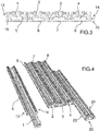
- the installation I is composed of several bars 1,2,3,4 intended to be aligned in the same plane, each of the bars being housed in an insulating support 5,6, 7,8, and two end cross members 9,10 extending perpendicularly to the bars, said crosspieces being made of an insulating material, these crosspieces being intended to be fixed along their length at one end of the bars and to their supports by any appropriate means, and being intended to be fixed by their two opposite ends respectively on two uprights 11,12 belonging to a device for housing an electrical equipment such as a cabinet or an electrical cabinet.
- the insulating support of each of the conductive bars has a V-shaped cross section and is designed to hold the bars in their housing whatever the value of the current.
- This insulating support has on its lateral faces 13,14 respectively a clip 15 and a slide 16 over the entire length thereof. This clip 15 and this slide 16 allow, when several supports are assembled, to hold the bars together, and to obtain the necessary electrodynamic resistance to the required level of the installation.
- this system of clip and slide along the entire length makes it possible to avoid the repetition of the transverse supports t several times over the entire length of the bars, such as this is the case for the busbars of the prior art, which allows to obtain full accessibility to the connection surface on the bar.
- each support is constituted by a U-shaped cross section piece, comprising a bottom wall intended to receive a bar flat and two side walls or flanks comprising the aforementioned fixing means.
- these high 9 and low 10 crossbars can be replaced by lateral fastening lugs 19 fixed by a clip or a slide to the supports, these clip and slide cooperating respectively with a slide or a clip provided in a side wall of the insulating supports bars.
- fastening tabs can be used to reinforce the electrodynamic resistance of the assembly.
- the bars 1,2,3,4 can be arranged in different ways for example flat, as illustrated on the figure 6 , or in a staged manner as described in figure 7 , in order to allow easy distribution to the left side g or to the right side d of the busbar.
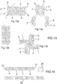
- the insulating support is shaped so as to receive bars of different sections, 1a, 1b, 1c, 1d, 1e, 1f, 1g, 1h, as illustrated respectively on the Figures 8,9 and 10 as well as different types of bars 1i, 1j, 1k, 11, such as a copper bar, an aluminum bar, a coated aluminum bar or others.
- an insulating plug 20 may be introduced into an insulating support 5 of bars, so as to define two different busbars 1.1 'in order to respond to different cases of electrical distribution such as, for example, arrival and departure with protection between, the source inverters, etc.
- one of the cross members 9, 10 has one or more registration zones 21 in order to specify characteristic values of the current distribution.
- these supports 5, 6, 7, 8 can be associated in different ways to form, for example, a set of flat bars, square bars or other types of bar association, depending on the type of installation in which they are likely to be arranged.
- the busbar according to the invention is constituted by example of two sets e, f of bars arranged back to back, each set being constituted by two bars 1,2 and 3,4 and their respective supports 5,6 and 7,8 associated laterally, the two sets e, f s' extending parallel to each other, this assembly being arranged horizontally.
- the busbar comprises a first set g of two bars 1,2 and their respective supports 5,6 arranged back to back, and a second set h comprising two other bars 3,4 arranged respectively on either side of the above set g and below.
- this set of bars consists of four bars 1, 2, 3, 4 in their support 5 to 8 arranged in a star.
- each insulating support comprises on either side of the bar disposed flat, or the base 22 of the aforementioned U, fastening means to another support, this allowing an arrangement of the bars next to each other, parallel to each other.
- This fixing in this position is achieved by means of two longitudinal sidewalls 23,24 respectively belonging respectively to two supports arranged side by side, these sidewalls comprising the aforementioned clips and slides.
- these clips have a cross section comprising a semicircular portion connected to the main part of the insulating support by a rectangular portion.
- each insulating support 5 to 8 comprises at one of its ends both a clip and a slide, these two elements extending in two directions substantially perpendicular to one another.
- spacers 25 in the form of an accessory can be used between two insulating supports and use the clips 15 or side slides 16 of the insulating supports 5 to 8 for their attachment, so as to achieve different between position axis bars between them in order to allow the use of these according to different standards.
- the insulation obtained thanks to the insulating support 5 to 8 of each of the bars 1 to 4 makes it possible to avoid excessive distances in the air and thus makes it possible to improve the compactness of the solution.
- the flat association of the insulating supports 5 to 8 makes it possible to keep a minimum space requirement to a minimum because of the complete insulation of the bars.
- the busbar supports are traditionally positioned transverse to the busbars and are defined to leave a distance in the air and a distance of sufficient path currents between the bare busbars itself and with respect to the outside environment.
- the complete insulation of the busbars and the integration of the fixing of the insulating supports between them makes it possible to minimize the distances in the air and the tracking currents making it possible to obtain a compact solution that eliminates the risks of an electric arc.
- This insulator of which the supports are constituted, can be put in contact with metal parts 26 of an envelope E.
- This insulating material is designed so as to promote the heat dissipation associated with the passage of the current, it facilitates the heat exchange and these supports, once pressed against this wall of metal casing 26 or other, promote the heat exchange towards the outside of the envelope E.
- dissipation radiators 27 may be placed inside the insulating supports 5 to 8, at one or both ends of each bar 1 to 4.
- a chimney system can be associated with the bars, so as to allow the flow of air flow to optimize the cooling of the conductors.
- These same chimneys can be associated with zones of air clearance or arrival during the installation in an envelope. These chimneys allow the circulation of up and down the air over the entire length of the bar to help the natural or forced circulation of ambient air.
- particular shapes may be defined on the conductor or on the insulating supports in order to promote circulation.
- the insulating support 5 is designed to be equipped with a breakable cover 28 to make the entire conductor bar completely protected from the electrical contacts and let only the connections necessary for the operation of the installation.
- this insulating support comprises clipping means 29 of the cover 28.
- one or more supports 5 are used without a conductive bar inside so as to be able to install instead systems 30 for managing the communication inside the boards or for managing cables vertically knowing that the insulating support can also be equipped with a screen 32 to preserve disturbances related to electromagnetic compatibility.
- the clipping area of the cover is also used to receive bracelets 33 or other type of hold management accessories.
- the installation made according to the invention is designed to be able to receive several m bar locations to make a unipolar, bipolar, tripolar or tetra polar distribution, knowing that each of the solutions can be variegated according to configurations and any type of diagram electric.
- the figure 20a illustrates the fact that the installation can be unipolar, bipolar, tripolar or tetra polar type.
- the figure 20b illustrates that the installation can be installed on the left, center, right or distributed in relation to the transverse support.
- the figure 20c illustrates an installation with a double neutral.
- the figure 20d illustrates a dual distribution for source inverters.
- the figure 20e illustrates a two-by-two installation of bars for each phase type, which doubles the capacity of the busbar in the same size.
- the figure 20f illustrates an installation in which a mixing of the current typology is performed, said installation comprising a polar tetra busbar AC with a bi-polar DC busbar.
- the figure 20g illustrates an installation according to the invention, comprising only a ground bar.
- marking zones can also be provided on the profile of the support.
Landscapes
- Engineering & Computer Science (AREA)
- Power Engineering (AREA)
- Patch Boards (AREA)
- Installation Of Bus-Bars (AREA)
Applications Claiming Priority (1)
| Application Number | Priority Date | Filing Date | Title |
|---|---|---|---|
| FR1662402A FR3060224B1 (fr) | 2016-12-14 | 2016-12-14 | Installation de distribution electrique a basse tension |
Publications (2)
| Publication Number | Publication Date |
|---|---|
| EP3336983A1 true EP3336983A1 (de) | 2018-06-20 |
| EP3336983B1 EP3336983B1 (de) | 2026-04-15 |
Family
ID=58501512
Family Applications (1)
| Application Number | Title | Priority Date | Filing Date |
|---|---|---|---|
| EP17200714.8A Active EP3336983B1 (de) | 2016-12-14 | 2017-11-09 | Niederspannungs-stromverteilungsanlage |
Country Status (4)
| Country | Link |
|---|---|
| US (1) | US10340670B2 (de) |
| EP (1) | EP3336983B1 (de) |
| CN (1) | CN108233188B (de) |
| FR (1) | FR3060224B1 (de) |
Families Citing this family (3)
| Publication number | Priority date | Publication date | Assignee | Title |
|---|---|---|---|---|
| FR3090094B1 (fr) * | 2018-12-12 | 2020-11-20 | Sagemcom Energy & Telecom Sas | Compteur électrique ayant un accès à la connectique situé sur la face arrière |
| CA3064104A1 (en) * | 2018-12-14 | 2020-06-14 | Eaton Intelligent Power Limited | Conductor for a power distribution system |
| CN110957652B (zh) * | 2019-12-09 | 2021-12-28 | 江阴市天马电源制造有限公司 | 一种模块化电源装配方法 |
Citations (3)
| Publication number | Priority date | Publication date | Assignee | Title |
|---|---|---|---|---|
| EP2086077A2 (de) * | 2008-02-02 | 2009-08-05 | Weidmüller Interface GmbH & Co. KG | Montagesystem für elektrische und/oder mechanische Komponenten |
| EP2164136A2 (de) * | 2008-09-15 | 2010-03-17 | Bticino S.P.A. | Lamellenkontaktkäfig |
| WO2014064617A2 (en) * | 2012-10-24 | 2014-05-01 | Elsteel (Pvt) Ltd | Plug & power motherboard |
Family Cites Families (16)
| Publication number | Priority date | Publication date | Assignee | Title |
|---|---|---|---|---|
| US4030794A (en) * | 1974-10-07 | 1977-06-21 | Square D Company | Bus bar and switchboard assemblage |
| FR2598562B1 (fr) | 1986-05-07 | 1988-07-29 | Merlin Gerin | Tableau basse tension, notamment d'un poste de distribution publique |
| FR2636786B1 (fr) | 1988-09-21 | 1990-11-16 | Alsthom Gec | Systeme de distribution electrique a basse tension |
| US6888066B1 (en) * | 2003-10-14 | 2005-05-03 | Siemens Energy & Automation, Inc. | Channel bus splice assembly |
| US6934147B2 (en) * | 2004-01-26 | 2005-08-23 | General Electric Company | Switchgear conductors and connections therefore |
| DE102005003199A1 (de) * | 2004-08-24 | 2006-03-02 | Weidmüller Interface GmbH & Co. KG | Montage- und Anschluß-System für elektrische Geräte |
| CN101499629B (zh) * | 2008-01-29 | 2012-03-28 | 北京基业达电气有限公司 | 配电箱母排及绝缘支撑防护系统 |
| DE202008015309U1 (de) * | 2008-02-02 | 2009-08-13 | Weidmüller Interface GmbH & Co. KG | Montagesystem für elektrische und/oder mechanische Komponenten |
| US8379374B2 (en) * | 2010-07-16 | 2013-02-19 | Rockwell Automation Technologies, Inc. | Bus to bus power interconnect |
| US8619411B2 (en) * | 2011-11-03 | 2013-12-31 | Schneider Electric, USA, Inc. | Switchgear bus assembly having reduced power loss, material and temperature |
| US8829346B2 (en) * | 2012-02-24 | 2014-09-09 | Siemens Industry, Inc. | Bus bar retention snaps for a base pan assembly |
| CN202454907U (zh) * | 2012-03-06 | 2012-09-26 | 厦门磐晟电气设备有限公司 | 低压开关柜顶水平母排系统 |
| US8921701B2 (en) * | 2012-09-04 | 2014-12-30 | General Electric Copany | Modular insulator for busbar support and method of assembling |
| EP2806517B1 (de) * | 2013-05-20 | 2023-04-12 | ABB S.p.A. | Sammelschiene für Stromverteilung |
| CN204144691U (zh) * | 2014-11-04 | 2015-02-04 | 中骏电气(厦门)有限公司 | 断路器进线柜的铜排安装结构 |
| CN105610055B (zh) * | 2016-01-29 | 2018-07-17 | 南京大全电气有限公司 | 低压配电柜主母排搭接装置和搭接方法 |
-
2016
- 2016-12-14 FR FR1662402A patent/FR3060224B1/fr active Active
-
2017
- 2017-11-09 EP EP17200714.8A patent/EP3336983B1/de active Active
- 2017-11-17 US US15/816,273 patent/US10340670B2/en active Active
- 2017-12-14 CN CN201711338476.6A patent/CN108233188B/zh active Active
Patent Citations (3)
| Publication number | Priority date | Publication date | Assignee | Title |
|---|---|---|---|---|
| EP2086077A2 (de) * | 2008-02-02 | 2009-08-05 | Weidmüller Interface GmbH & Co. KG | Montagesystem für elektrische und/oder mechanische Komponenten |
| EP2164136A2 (de) * | 2008-09-15 | 2010-03-17 | Bticino S.P.A. | Lamellenkontaktkäfig |
| WO2014064617A2 (en) * | 2012-10-24 | 2014-05-01 | Elsteel (Pvt) Ltd | Plug & power motherboard |
Also Published As
| Publication number | Publication date |
|---|---|
| FR3060224A1 (fr) | 2018-06-15 |
| EP3336983B1 (de) | 2026-04-15 |
| US20180166865A1 (en) | 2018-06-14 |
| FR3060224B1 (fr) | 2020-10-02 |
| CN108233188A (zh) | 2018-06-29 |
| CN108233188B (zh) | 2021-03-19 |
| US10340670B2 (en) | 2019-07-02 |
Similar Documents
| Publication | Publication Date | Title |
|---|---|---|
| EP2779334B1 (de) | Schaltschrank mit verbesserter mechanischer Anordnung | |
| EP0330525B1 (de) | Vorgefertigte elektrische Kanalisation, anwendbar auf mehrere Nennströme vom Typ bestehend aus einem flachen kannelierten Isolationsträger für Leiterschienen | |
| EP0681355B1 (de) | Sammelschienenanordnung, insbesondere für eine Energieverteilungsschrank | |
| FR2824429A1 (fr) | Bloc modulaire a fusibles pour bornes | |
| EP0109881B1 (de) | Profilschiene zur Befestigung von Apparaten für einen elektrischen Niederspannungsverteilerkasten oder eine Niederspannungsverteilertafel | |
| EP3336983B1 (de) | Niederspannungs-stromverteilungsanlage | |
| EP1376638B1 (de) | Elektromagnetischer Schutz und Steuereinheit | |
| FR2806519A1 (fr) | Dispositif d'assemblage et de raccordement electrique d'appareils electriques modulaires | |
| EP0396437A1 (de) | Leistungsverteilervorrichtung für elektrische Einrichtung | |
| EP1903647A1 (de) | Verteilereinheit, die elektrische Geräte im Modulformat umfasst | |
| EP0837534A1 (de) | Trag- und Stromeinspeisungsvorrichtung für elektrisches Gerät | |
| FR2847732A1 (fr) | Dispositif de distribution d'energie pour appareillages electriques disposes sur des rangees paralleles d'un tableau ou d'une armoire electrique | |
| EP2383849A1 (de) | Vertikale elektrisch leitenden Verbindungsvorrichtung | |
| EP3503318B1 (de) | Stromverteilungsvorrichtung, insbesondere in einem elektrischen schaltschrank oder einer elektrischen schalttafel | |
| EP0161984B1 (de) | Anschlussblock für ein elektrisches Schaltfeld | |
| EP0360237B1 (de) | Elektrisches Niederspannungsverteilsystem | |
| FR2807578A1 (fr) | Montant de chassis formant simultanement conduit de distribution et de repartition de l'energie electrique a differents niveaux de branchement d'appareillages | |
| EP0335756B1 (de) | Anschlussvorrichtung zum Verbinden von zwei Kabelkanalenden | |
| EP4072007A1 (de) | Modulares fotovoltaiksystem | |
| FR2791478A1 (fr) | Systeme de distribution d'energie electrique dans les etages d'un immeuble | |
| WO2026037920A1 (fr) | Interface de raccordement universel pour inverseur de source ou armoire électrique de puissance | |
| WO2024110696A1 (fr) | Ensemble d'assemblage d'au moins un appareil electrique modulaire a un rail de montage pour un coffret de distribution, appareil electrique modulaire, rail de montage et coffret de distribution electrique associes, | |
| FR2684246A1 (fr) | Installation de commutation isolee par un gaz. | |
| FR3029346A1 (fr) | Enveloppe metallique pour dispositif de commutation electrique | |
| FR2962604A1 (fr) | "grille de fausse coupure de reseau electrique et grille multi-fonctionnelle comprenant une telle grille ainsi qu'une grille optionnelle". |
Legal Events
| Date | Code | Title | Description |
|---|---|---|---|
| PUAI | Public reference made under article 153(3) epc to a published international application that has entered the european phase |
Free format text: ORIGINAL CODE: 0009012 |
|
| STAA | Information on the status of an ep patent application or granted ep patent |
Free format text: STATUS: THE APPLICATION HAS BEEN PUBLISHED |
|
| AK | Designated contracting states |
Kind code of ref document: A1 Designated state(s): AL AT BE BG CH CY CZ DE DK EE ES FI FR GB GR HR HU IE IS IT LI LT LU LV MC MK MT NL NO PL PT RO RS SE SI SK SM TR |
|
| AX | Request for extension of the european patent |
Extension state: BA ME |
|
| STAA | Information on the status of an ep patent application or granted ep patent |
Free format text: STATUS: REQUEST FOR EXAMINATION WAS MADE |
|
| 17P | Request for examination filed |
Effective date: 20180628 |
|
| RBV | Designated contracting states (corrected) |
Designated state(s): AL AT BE BG CH CY CZ DE DK EE ES FI FR GB GR HR HU IE IS IT LI LT LU LV MC MK MT NL NO PL PT RO RS SE SI SK SM TR |
|
| STAA | Information on the status of an ep patent application or granted ep patent |
Free format text: STATUS: EXAMINATION IS IN PROGRESS |
|
| 17Q | First examination report despatched |
Effective date: 20200511 |
|
| GRAP | Despatch of communication of intention to grant a patent |
Free format text: ORIGINAL CODE: EPIDOSNIGR1 |
|
| STAA | Information on the status of an ep patent application or granted ep patent |
Free format text: STATUS: GRANT OF PATENT IS INTENDED |
|
| INTG | Intention to grant announced |
Effective date: 20251201 |
|
| GRAS | Grant fee paid |
Free format text: ORIGINAL CODE: EPIDOSNIGR3 |
|
| GRAA | (expected) grant |
Free format text: ORIGINAL CODE: 0009210 |
|
| STAA | Information on the status of an ep patent application or granted ep patent |
Free format text: STATUS: THE PATENT HAS BEEN GRANTED |
|
| AK | Designated contracting states |
Kind code of ref document: B1 Designated state(s): AL AT BE BG CH CY CZ DE DK EE ES FI FR GB GR HR HU IE IS IT LI LT LU LV MC MK MT NL NO PL PT RO RS SE SI SK SM TR |
|
| REG | Reference to a national code |
Ref country code: CH Ref legal event code: F10 Free format text: ST27 STATUS EVENT CODE: U-0-0-F10-F00 (AS PROVIDED BY THE NATIONAL OFFICE) Effective date: 20260415 Ref country code: GB Ref legal event code: FG4D Free format text: NOT ENGLISH |
|
| REG | Reference to a national code |
Ref country code: IE Ref legal event code: FG4D Free format text: LANGUAGE OF EP DOCUMENT: FRENCH |
|
| REG | Reference to a national code |
Ref country code: DE Ref legal event code: R096 Ref document number: 602017094797 Country of ref document: DE |