EP3336986B1 - Dispositif destiné à guider au moins deux conduites ainsi que matière de raccordement comprenant un tel dispositif - Google Patents
Dispositif destiné à guider au moins deux conduites ainsi que matière de raccordement comprenant un tel dispositif Download PDFInfo
- Publication number
- EP3336986B1 EP3336986B1 EP17204341.6A EP17204341A EP3336986B1 EP 3336986 B1 EP3336986 B1 EP 3336986B1 EP 17204341 A EP17204341 A EP 17204341A EP 3336986 B1 EP3336986 B1 EP 3336986B1
- Authority
- EP
- European Patent Office
- Prior art keywords
- lines
- basic body
- section
- slide
- material according
- Prior art date
- Legal status (The legal status is an assumption and is not a legal conclusion. Google has not performed a legal analysis and makes no representation as to the accuracy of the status listed.)
- Active
Links
Images


Classifications
-
- H—ELECTRICITY
- H02—GENERATION; CONVERSION OR DISTRIBUTION OF ELECTRIC POWER
- H02G—INSTALLATION OF ELECTRIC CABLES OR LINES, OR OF COMBINED OPTICAL AND ELECTRIC CABLES OR LINES
- H02G1/00—Methods or apparatus specially adapted for installing, maintaining, repairing or dismantling electric cables or lines
- H02G1/06—Methods or apparatus specially adapted for installing, maintaining, repairing or dismantling electric cables or lines for laying cables, e.g. laying apparatus on vehicle
- H02G1/08—Methods or apparatus specially adapted for installing, maintaining, repairing or dismantling electric cables or lines for laying cables, e.g. laying apparatus on vehicle through tubing or conduit, e.g. rod or draw wire for pushing or pulling
- H02G1/085—Methods or apparatus specially adapted for installing, maintaining, repairing or dismantling electric cables or lines for laying cables, e.g. laying apparatus on vehicle through tubing or conduit, e.g. rod or draw wire for pushing or pulling using portable tools
-
- H—ELECTRICITY
- H02—GENERATION; CONVERSION OR DISTRIBUTION OF ELECTRIC POWER
- H02G—INSTALLATION OF ELECTRIC CABLES OR LINES, OR OF COMBINED OPTICAL AND ELECTRIC CABLES OR LINES
- H02G3/00—Installations of electric cables or lines or protective tubing therefor in or on buildings, equivalent structures or vehicles
- H02G3/02—Details
- H02G3/04—Protective tubing or conduits, e.g. cable ladders or cable troughs
- H02G3/0462—Tubings, i.e. having a closed section
- H02G3/0481—Tubings, i.e. having a closed section with a circular cross-section
Definitions
- the present invention relates to a connection material for transmitting a broadband powerline signal via a power supply network.
- an energy supply network is used to exchange communication signals between the participants in the system.
- the signals or data to be transmitted are modulated in the higher frequency range on one or more lines of the power supply network, for example on one phase relative to the neutral conductor or between two phases.
- BPL Powerline Communication - broadband powerline
- the lines of the connection material that is used to couple a BPL signal in or out of an electrical system it is necessary to route them in as exact an alignment as possible. This is problematic insofar as, in particular, the section of the connection material that is coupled to an electrical system, for example a street distributor, is present as individually routed, separate lines. Since the lines in this section do not run in a defined position to one another, the wave impedance of the lines increases, which sometimes leads to strong attenuation of the BPL signal.
- the US 2007/0277995 A1 shows a double cable for headphones, a first cable being surrounded by slotted insulation.
- a second cable can be introduced into the slot with the aid of a slider and removed from it.
- the CH 384 355 A , WO 02/052686 A2 and DE 10 2007 038 327 A1 also describe devices for guiding a cable. Furthermore, the documents concern WO 2005/074214 A1 and EP 2 437 074 A2 the transmission of a broadband powerline signal.
- the present invention is based on the object of specifying a connection material in which the lines can be guided at a defined distance from one another using structurally simple means.
- the disclosure further relates to a device for guiding at least two lines, in particular for data transmission, specified, comprising a base body for receiving the lines, the base body having at least in some areas a slot extending in the longitudinal direction, a slide being arranged on the base body, wherein the slide can be moved along the longitudinal direction of the base body and wherein at least one of the lines can be introduced into the base body and / or removed from the base body by means of the slide through the slot.
- the arrangement of a base body accommodating the lines allows the lines to be guided in a simple manner in a defined position to one another. Furthermore, the base body has a slot running in the longitudinal direction of the base body, through which at least one of the lines can be introduced into the base body or removed from it.
- a slide is provided for this purpose, which can be moved along the longitudinal direction of the base body and via which at least one of the lines is pushed into and / or pulled out of the base body through the slot, depending on the direction in which the slide is moved.
- the device is very easy to handle even in a confined space and with protective gloves.
- lines can be led extremely easily to one another in a defined position and also removed from one another or detached again, so that the device can be used extremely flexibly and multiple use is also possible.
- Another advantage is that the line in contact with the slide is at least slightly secured by the slide against further withdrawal and / or introduction into the base body.
- the base body is advantageously designed in one piece.
- the base body consists of several individual parts. It is essential that the lines located in the main body are guided to one another in a defined position and that at least one of the lines can be introduced through the slot into the main body or a cavity formed in the main body and can be removed from it.
- a slot is to be understood as an opening which is sufficiently large to allow a line to pass through.
- the edges of the slot can be at least slightly pretensioned so that they are essentially against one another when the line has passed the slot. It is thereby achieved that the opening made by the slot is at least substantially closed and the line is securely received in the base body.
- a line is to be understood as an electrical conductor for transmitting a signal, in particular a BPL signal, which has an insulating sheath.
- a single-core cable comprises only a single conductor.
- One multi-core cable is formed by at least two mutually insulated, combined conductors.
- the lines advantageously run essentially parallel to one another within the base body. This ensures that the wave impedance of the lines is minimized, so that the attenuation of the signal to be transmitted is reduced. In particular, it is advantageous if the lines run with the smallest possible spacing from one another.
- the base body has an elongated shape.
- the base body can, for example, be designed to be essentially straight.
- the geometry of the base body is adapted to the installation situation, the base body is designed, for example, curved. It is essential that the lines within the base body run in a defined orientation - preferably parallel - to one another.
- the base body is designed as a tube, the tube not necessarily having to have a round cross section.
- the pipe can for example consist of a non-conductive material, in particular polyvinyl chloride (PVC).
- PVC polyvinyl chloride
- the lines can be introduced into the pipe through the slot extending in the longitudinal direction, at least one of the lines being able to be introduced into the pipe and / or out of the pipe by means of the slide which can be moved along the pipe.
- two slots are formed on the base body.
- the slots can be implemented, for example, on opposite sides of the base body, so that the electrical lines can each be introduced into and removed from the base body through their own, separate slot. It is conceivable that two cavities which are separate from one another run in the base body, one of the slots in each case realizing a passage to one of the cavities. As a result, the conductors can be received in separate cavities in the base body.
- the term cavity is to be understood in the broadest sense in relation to the device according to the invention, namely it is only necessary that one or more lines can be arranged within the base body.
- the base body can consist of an elastic material and be essentially solid or filled with an elastic material, so that the required cavity is created by the introduction of the line.
- the slide can at least partially enclose the base body - in the circumferential direction.
- the slide is securely arranged on the base body and can be moved along the longitudinal direction of the base body.
- the slide can be a ring that is pushed over the base body.
- the line can be pushed into or pulled out of the base body by moving the ring.
- the slide partially encloses the base body in the circumferential direction, so that the slide is connected to the base body in a fixed manner and movable in the longitudinal direction. Any form-fitting and / or non-positive connection between the base body and slide is conceivable, which enables the slide to be moved in the longitudinal direction of the base body.
- the slide can be fixed at least in a defined position on the base body, for example it can be clamped or latched, so that a movement in the longitudinal direction is prevented.
- the position is defined in which it penetrates the base body or exits it.
- the slide has at least one passage through which the line is passed.
- the line is pulled out of or inserted into the base body, depending on the direction of movement of the slide.
- the slide has several passages, corresponding to the number of electrical lines, so that each of the lines can be passed through a separate passage.
- several lines can be passed through a single passage.
- the slide is made of a non-conductive or poorly conductive material.
- This can be a plastic, for example polyvinyl chloride.
- the base body is at least partially filled with an insulating material, in particular polyvinyl chloride.
- the lines are insulated again by the insulating material and it is also possible to route the lines more precisely, namely due to the reduced cavity within the base body.
- a slot extending in the longitudinal direction of the base body is formed in the insulating material at least in some areas. A line can be passed through the slot and thus introduced into the base body.
- connection material for the transmission of a broadband powerline signal via a power supply network with a first section consisting of a multi-core, in particular three-core, line and a second section consisting of two separate, in particular single-core, lines, the first section and the second Section are connected to each other, wherein a connection element for connecting to a broadband powerline modem is formed at a free end of the multi-core line of the first section, and at least at a free end of the lines of the second section a connection element for connecting to a connection means electrical system is formed, characterized in that a base body is arranged for receiving at least one area of the lines of the second section, that the base body has at least in some areas a slot extending in the longitudinal direction of the base body, that a Slide is arranged on the base body, that the slide can be moved along the longitudinal direction of the base body and has at least one passage for at least one line, that at least one of the lines can be introduced into the base body and
- a connecting element for connecting to an electrical device is formed at the free end of the multi-core line of the first section.
- This can be, for example, a plug connector that is designed to be connected to a broadband powerline modem.
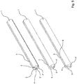
- the Fig. 1 and 2 show a schematic representation of a first exemplary embodiment of part of a connection material according to the invention.
- This has a base body 1 for receiving at least two lines 2, 2 '.
- a slide 3, which can be displaced along the longitudinal direction of the base body 1, is arranged on the base body 1.
- the base body 1 has a slot 4, which likewise extends in the longitudinal direction of the base body 1.
- the line 2 can be introduced into the cavity 5 of the base body 1 through the slot 4.
- the slide 2 has a passage 6 through which the line 2 is passed.
- the line 2 - depending on the direction of movement - is pressed or inserted into the base body 1 or pulled out of the base body 1 or brought out.
- the slide 2 can also be very easily operate when the fitter is wearing protective gloves and there is little space available for handling the device.
- a second cavity 5 ' is formed, which is used to receive the second line 2'.
- the cavities 5, 5 ' are separated from one another by an insulating material 7, for example PVC.
- the base body 1 is designed in one piece.
- the insulating material 7 also has a slot running in the longitudinal direction in order to introduce the second line 2 'through the slot into the cavity 5'.
- a further slot can be formed on the base body 1, through which the second line 2 'can be introduced into the cavity 5' or removed from it.
- the line 2 ' is essentially fixedly arranged in the cavity 5' and only the line 2 can be removed from the cavity 5 and thus from the base body 1 and can be reintroduced.
- edges 8 of the slot 4 almost touch each other, so that the cavity 5 is essentially closed when the line 2 is brought in or out.
- the edges 8 can be pretensioned in such a way that they touch each other when the line 2 is inserted or removed.
- Fig. 3 and 4th is the slide 3 of the in the Fig. 1 and 2 shown embodiment.
- the slide 3 has a radially inwardly extending projection 9 with which it engages in the slot 4 of the base body 1.
- the projection 9 prevents the slide 3 from rotating relative to the base body 2.
- the projection 9 spreads the edges 8 apart so that the line 1 can be brought in or out more easily.
- Fig. 5 several configurations of the base body 1 are shown. This can accommodate, for example, two or three lines 2, 2 ', 2 ". Depending on how many cavities 5, 5', 5" have a slot 4, the slide 3 is to be adapted accordingly, namely according to the figure shown in FIG Fig. 2 and 3 illustrated embodiment.
- FIG. 6 to 9 a further embodiment of a part of a connection material according to the invention is shown.
- This comprises a base body 1 for receiving two lines 2, 2 '.
- the line 2 can be introduced into and removed from the base body 1 through a slider 3 through the slot 4.
- the slide 3 surrounds the base body 1 and has a projection 9 with which it engages in the slot 4.
- the slide 3 can be made from a bent wire.
- the slide 3 is made of a plastic.
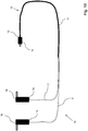
- Fig. 10 shows a schematic representation of part of a connection material according to the invention.
- the connection material has a first section 10, which consists of a three-wire line 11.
- the first section 10 is connected to the second section 12.
- the second section 12 consists of two separate, single-core lines 2, 2 '.
- a plug connector 14 for coupling to a broadband powerline modem is formed.
- the free ends 15 of the lines 2, 2 'of the second section each have a connection element 16 for connecting to a connection means of an electrical system, in particular a low-voltage high-performance load strip.
- the lines 2, 2' are arranged or guided at least in some areas in a device according to the invention. It is thereby achieved that the conductors 2, 2 'are guided at a defined, small distance from one another, the distance at most varying slightly over the length of the lines 2, 2'. With such an arrangement, the wave impedance of the conductors is minimized, which leads to an improvement in the signal transmission.
Landscapes
- Engineering & Computer Science (AREA)
- Architecture (AREA)
- Civil Engineering (AREA)
- Structural Engineering (AREA)
- Electric Cable Arrangement Between Relatively Moving Parts (AREA)
- Connector Housings Or Holding Contact Members (AREA)
Claims (12)
- Matériel de raccordement pour la transmission d'un signal de ligne électrique à large bande via un réseau d'alimentation, comportant une première section (10) constituée d'une ligne multiconducteur, notamment à trois conducteurs (11) et une deuxième section (12) constituée de deux lignes séparées, notamment à conducteur unique (2, 2'), dans lequel la première section (10) et la deuxième section (12) sont reliées l'une à l'autre, dans lequel un élément de connexion pour la connexion à un modem de ligne électrique à large bande est réalisé à une extrémité libre (14) de la ligne multiconducteur (11) de la première section (10), et dans lequel un élément de connexion (16) pour la connexion à un moyen de connexion d'un système électrique est réalisé au moins à une extrémité libre (15) des lignes de la deuxième section (12), dans lequel un corps de base (1) est agencé pour recevoir au moins une zone des lignes (2, 2') de la deuxième section (12), le corps de base (1) présente au moins par endroits une fente (4) s'étendant dans la direction longitudinale du corps de base (1), un coulisseau (3) est disposé sur le corps de base (1), le coulisseau (3) peut être déplacé le long de la direction longitudinale du corps de base (1) et comporte au moins un passage (6) pour au moins une ligne (2, 2'), au moins une des lignes (2, 2') au moyen du coulisseau (3) peut être introduite à travers la fente (4) dans le corps de base (1) et/ou retirée du corps de base (1) et que le coulisseau présente une saillie (9) s'étendant radialement vers l'intérieur, avec laquelle il s'engage dans la fente (4) du corps de base (1).
- Matériel de raccordement selon la revendication 1, dans lequel à l'extrémité libre (14) de la ligne multiconducteur (11) de la première section (10) est réalisé un connecteur (14) pour la connexion à un modem de ligne électrique à large bande.
- Matériel de raccordement selon la revendication 1 ou 2, dans lequel à au moins une des extrémités libres (15) des lignes de la deuxième section (12) est réalisé un élément de connexion (16) pour la connexion à un moyen de connexion d'un système électrique, à savoir une barrette de charge basse tension haute performance.
- Matériel de raccordement selon une des revendications 1 à 3, dans lequel les lignes (2,2') s'étendent essentiellement parallèlement les unes aux autres à l'intérieur du corps de base (1).
- Matériel de raccordement selon une des revendications 1 à 4, dans lequel le corps de base (1) présente une forme allongée
- Matériel de raccordement selon une des revendications 1 à 5, dans lequel le corps de base (1) est réalisé sous la forme d'un tube, notamment en un matériau non conducteur, par exemple en polychlorure de vinyle.
- Matériel de raccordement selon une des revendications 1 à 6, dans lequel le corps de base (1) présente deux fentes (4), de préférence sur des côtés opposés du corps de base (1).
- Matériel de raccordement selon une des revendications 1 à 7, dans lequel le coulisseau (3) enserre au moins partiellement le corps de base (1).
- Matériel de raccordement selon une des revendications 1 à 8, dans lequel deux passages (6) sont ménagés sur le coulisseau (3).
- Matériel de raccordement selon une des revendications 1 à 9, dans lequel le coulisseau (3) est réalisé en un matériau non conducteur, notamment en matière plastique, de préférence en polychlorure de vinyle.
- Matériel de raccordement selon une des revendications 1 à 10, dans lequel le corps de base (1) est rempli partiellement avec un matériau isolant (7), notamment une matière plastique, par exemple du polychlorure de vinyle.
- Matériel de raccordement selon la revendication 11, dans lequel une fente s'étendant dans la direction longitudinale du corps de base (1) est réalisée dans le matériau isolant (7), au moins par endroits.
Applications Claiming Priority (2)
| Application Number | Priority Date | Filing Date | Title |
|---|---|---|---|
| DE102016225322 | 2016-12-16 | ||
| DE102017204245.1A DE102017204245A1 (de) | 2016-12-16 | 2017-03-14 | Vorrichtung zum Führen von mindestens zwei Leitungen sowie ein Anschlussmaterial umfassend eine solche Vorrichtung |
Publications (2)
| Publication Number | Publication Date |
|---|---|
| EP3336986A1 EP3336986A1 (fr) | 2018-06-20 |
| EP3336986B1 true EP3336986B1 (fr) | 2021-10-20 |
Family
ID=60515191
Family Applications (1)
| Application Number | Title | Priority Date | Filing Date |
|---|---|---|---|
| EP17204341.6A Active EP3336986B1 (fr) | 2016-12-16 | 2017-11-29 | Dispositif destiné à guider au moins deux conduites ainsi que matière de raccordement comprenant un tel dispositif |
Country Status (1)
| Country | Link |
|---|---|
| EP (1) | EP3336986B1 (fr) |
Families Citing this family (1)
| Publication number | Priority date | Publication date | Assignee | Title |
|---|---|---|---|---|
| DE102022105851A1 (de) * | 2022-03-14 | 2023-09-14 | Lisa Dräxlmaier GmbH | Vorrichtung und verfahren zum umhüllen eines kabels mit einem selbstschliessenden schutzschlauch |
Citations (3)
| Publication number | Priority date | Publication date | Assignee | Title |
|---|---|---|---|---|
| WO2005074214A1 (fr) * | 2004-01-30 | 2005-08-11 | Skynetglobal Limited | Passerelle d'acces large bande a ligne de puissance |
| DE102007038327A1 (de) * | 2007-05-29 | 2008-12-04 | Sdk Company Ltd. | Elektrisches Kabel und tragbare Audiovorrichtung mit einem solchen Kabel |
| EP2437074A2 (fr) * | 2010-10-01 | 2012-04-04 | Broadcom Corporation | Dispositif de modem de réseau électrique |
Family Cites Families (3)
| Publication number | Priority date | Publication date | Assignee | Title |
|---|---|---|---|---|
| CH384355A (de) * | 1960-06-25 | 1964-11-15 | Vockenhuber Karl | Tragriemen für elektrische Geräte |
| WO2002052686A2 (fr) * | 2000-12-22 | 2002-07-04 | Perez Delgado Maria De Los Ang | Gaine aerienne flexible pour cables electriques |
| JP2007323847A (ja) * | 2006-05-30 | 2007-12-13 | Sdk Kk | 配線コード及びそれを用いた携帯用音響機器 |
-
2017
- 2017-11-29 EP EP17204341.6A patent/EP3336986B1/fr active Active
Patent Citations (3)
| Publication number | Priority date | Publication date | Assignee | Title |
|---|---|---|---|---|
| WO2005074214A1 (fr) * | 2004-01-30 | 2005-08-11 | Skynetglobal Limited | Passerelle d'acces large bande a ligne de puissance |
| DE102007038327A1 (de) * | 2007-05-29 | 2008-12-04 | Sdk Company Ltd. | Elektrisches Kabel und tragbare Audiovorrichtung mit einem solchen Kabel |
| EP2437074A2 (fr) * | 2010-10-01 | 2012-04-04 | Broadcom Corporation | Dispositif de modem de réseau électrique |
Also Published As
| Publication number | Publication date |
|---|---|
| EP3336986A1 (fr) | 2018-06-20 |
Similar Documents
| Publication | Publication Date | Title |
|---|---|---|
| DE1911315C3 (de) | Elektrisches Stromverteilungssystem | |
| EP2577804B1 (fr) | Répartiteur électrique | |
| EP3152809B1 (fr) | Appareil électrique | |
| EP2684253B1 (fr) | Dispositif et procédé de connexion pour signaux digitaux à haute fréquence | |
| DE4402837A1 (de) | Flachkabel | |
| EP2286489B1 (fr) | Connecteur d'une connexion enfichable | |
| DE102010017265A1 (de) | Kabelanschlusseinrichtung und Verfahren zum Anschließen eines Kabels an eine Kabelanschlusseinrichtung | |
| DE19604564C1 (de) | Anschlußdose für ein Datennetz | |
| EP3336986B1 (fr) | Dispositif destiné à guider au moins deux conduites ainsi que matière de raccordement comprenant un tel dispositif | |
| DE2712723A1 (de) | Elektrischer verteiler | |
| DE102009010326A1 (de) | Vorrichtung zur Aufnahme einer Leitung | |
| DE102017204245A1 (de) | Vorrichtung zum Führen von mindestens zwei Leitungen sowie ein Anschlussmaterial umfassend eine solche Vorrichtung | |
| DE3210223C2 (de) | Knieförmig gestaltete, steckbare Kabelgarnitur | |
| DE8213407U1 (de) | Kabelführungsaggregat | |
| DE102011004873B4 (de) | Flachbandkabelmantel für AS-Interface Systeme | |
| WO2000030218A1 (fr) | Dispositif de derivation pour cable | |
| WO2015140240A1 (fr) | Connecteur enfichable insensible aux interférences | |
| DE102017131062B3 (de) | Steckdose | |
| DE102012009405B4 (de) | Vorrichtung zum elektrischen Verbinden von Hauptleitern eines Energieversorgungskabels mit jeweils mindestens einem Abzweigleiter | |
| WO2018046576A1 (fr) | Elément de connexion électrique et dispositif formant pont transversal pour bornes électriques | |
| DE9113317U1 (de) | Anschlußdose für elektrische Leiter von Kabeln und/oder Schnüren der Telekommunikationstechnik | |
| WO2016058689A1 (fr) | Unité d'installation électrique ainsi que procédé pour le raccordement d'au moins une unité d'installation électrique à un câble, en particulier à un câble rond, à un câble en nappe ou à un fil plat | |
| EP2804267B1 (fr) | Décharge de traction pour connecteur à fiches | |
| DE60200782T2 (de) | Kamm und Verfahren zur Abzweigung für eine bestehende Leitung | |
| EP3176882A1 (fr) | Élément de couplage ayant une conduite électrique raccordée |
Legal Events
| Date | Code | Title | Description |
|---|---|---|---|
| PUAI | Public reference made under article 153(3) epc to a published international application that has entered the european phase |
Free format text: ORIGINAL CODE: 0009012 |
|
| STAA | Information on the status of an ep patent application or granted ep patent |
Free format text: STATUS: THE APPLICATION HAS BEEN PUBLISHED |
|
| AK | Designated contracting states |
Kind code of ref document: A1 Designated state(s): AL AT BE BG CH CY CZ DE DK EE ES FI FR GB GR HR HU IE IS IT LI LT LU LV MC MK MT NL NO PL PT RO RS SE SI SK SM TR |
|
| AX | Request for extension of the european patent |
Extension state: BA ME |
|
| STAA | Information on the status of an ep patent application or granted ep patent |
Free format text: STATUS: REQUEST FOR EXAMINATION WAS MADE |
|
| 17P | Request for examination filed |
Effective date: 20181018 |
|
| RBV | Designated contracting states (corrected) |
Designated state(s): AL AT BE BG CH CY CZ DE DK EE ES FI FR GB GR HR HU IE IS IT LI LT LU LV MC MK MT NL NO PL PT RO RS SE SI SK SM TR |
|
| STAA | Information on the status of an ep patent application or granted ep patent |
Free format text: STATUS: EXAMINATION IS IN PROGRESS |
|
| 17Q | First examination report despatched |
Effective date: 20191002 |
|
| GRAP | Despatch of communication of intention to grant a patent |
Free format text: ORIGINAL CODE: EPIDOSNIGR1 |
|
| STAA | Information on the status of an ep patent application or granted ep patent |
Free format text: STATUS: GRANT OF PATENT IS INTENDED |
|
| INTG | Intention to grant announced |
Effective date: 20210506 |
|
| GRAS | Grant fee paid |
Free format text: ORIGINAL CODE: EPIDOSNIGR3 |
|
| GRAA | (expected) grant |
Free format text: ORIGINAL CODE: 0009210 |
|
| STAA | Information on the status of an ep patent application or granted ep patent |
Free format text: STATUS: THE PATENT HAS BEEN GRANTED |
|
| AK | Designated contracting states |
Kind code of ref document: B1 Designated state(s): AL AT BE BG CH CY CZ DE DK EE ES FI FR GB GR HR HU IE IS IT LI LT LU LV MC MK MT NL NO PL PT RO RS SE SI SK SM TR |
|
| REG | Reference to a national code |
Ref country code: GB Ref legal event code: FG4D Free format text: NOT ENGLISH |
|
| REG | Reference to a national code |
Ref country code: CH Ref legal event code: EP |
|
| REG | Reference to a national code |
Ref country code: IE Ref legal event code: FG4D Free format text: LANGUAGE OF EP DOCUMENT: GERMAN |
|
| REG | Reference to a national code |
Ref country code: DE Ref legal event code: R096 Ref document number: 502017011768 Country of ref document: DE |
|
| REG | Reference to a national code |
Ref country code: AT Ref legal event code: REF Ref document number: 1440707 Country of ref document: AT Kind code of ref document: T Effective date: 20211115 |
|
| REG | Reference to a national code |
Ref country code: LT Ref legal event code: MG9D |
|
| REG | Reference to a national code |
Ref country code: NL Ref legal event code: MP Effective date: 20211020 |
|
| PG25 | Lapsed in a contracting state [announced via postgrant information from national office to epo] |
Ref country code: RS Free format text: LAPSE BECAUSE OF FAILURE TO SUBMIT A TRANSLATION OF THE DESCRIPTION OR TO PAY THE FEE WITHIN THE PRESCRIBED TIME-LIMIT Effective date: 20211020 Ref country code: LT Free format text: LAPSE BECAUSE OF FAILURE TO SUBMIT A TRANSLATION OF THE DESCRIPTION OR TO PAY THE FEE WITHIN THE PRESCRIBED TIME-LIMIT Effective date: 20211020 Ref country code: FI Free format text: LAPSE BECAUSE OF FAILURE TO SUBMIT A TRANSLATION OF THE DESCRIPTION OR TO PAY THE FEE WITHIN THE PRESCRIBED TIME-LIMIT Effective date: 20211020 Ref country code: BG Free format text: LAPSE BECAUSE OF FAILURE TO SUBMIT A TRANSLATION OF THE DESCRIPTION OR TO PAY THE FEE WITHIN THE PRESCRIBED TIME-LIMIT Effective date: 20220120 |
|
| PG25 | Lapsed in a contracting state [announced via postgrant information from national office to epo] |
Ref country code: IS Free format text: LAPSE BECAUSE OF FAILURE TO SUBMIT A TRANSLATION OF THE DESCRIPTION OR TO PAY THE FEE WITHIN THE PRESCRIBED TIME-LIMIT Effective date: 20220220 Ref country code: SE Free format text: LAPSE BECAUSE OF FAILURE TO SUBMIT A TRANSLATION OF THE DESCRIPTION OR TO PAY THE FEE WITHIN THE PRESCRIBED TIME-LIMIT Effective date: 20211020 Ref country code: PT Free format text: LAPSE BECAUSE OF FAILURE TO SUBMIT A TRANSLATION OF THE DESCRIPTION OR TO PAY THE FEE WITHIN THE PRESCRIBED TIME-LIMIT Effective date: 20220221 Ref country code: PL Free format text: LAPSE BECAUSE OF FAILURE TO SUBMIT A TRANSLATION OF THE DESCRIPTION OR TO PAY THE FEE WITHIN THE PRESCRIBED TIME-LIMIT Effective date: 20211020 Ref country code: NO Free format text: LAPSE BECAUSE OF FAILURE TO SUBMIT A TRANSLATION OF THE DESCRIPTION OR TO PAY THE FEE WITHIN THE PRESCRIBED TIME-LIMIT Effective date: 20220120 Ref country code: NL Free format text: LAPSE BECAUSE OF FAILURE TO SUBMIT A TRANSLATION OF THE DESCRIPTION OR TO PAY THE FEE WITHIN THE PRESCRIBED TIME-LIMIT Effective date: 20211020 Ref country code: LV Free format text: LAPSE BECAUSE OF FAILURE TO SUBMIT A TRANSLATION OF THE DESCRIPTION OR TO PAY THE FEE WITHIN THE PRESCRIBED TIME-LIMIT Effective date: 20211020 Ref country code: HR Free format text: LAPSE BECAUSE OF FAILURE TO SUBMIT A TRANSLATION OF THE DESCRIPTION OR TO PAY THE FEE WITHIN THE PRESCRIBED TIME-LIMIT Effective date: 20211020 Ref country code: GR Free format text: LAPSE BECAUSE OF FAILURE TO SUBMIT A TRANSLATION OF THE DESCRIPTION OR TO PAY THE FEE WITHIN THE PRESCRIBED TIME-LIMIT Effective date: 20220121 Ref country code: ES Free format text: LAPSE BECAUSE OF FAILURE TO SUBMIT A TRANSLATION OF THE DESCRIPTION OR TO PAY THE FEE WITHIN THE PRESCRIBED TIME-LIMIT Effective date: 20211020 |
|
| REG | Reference to a national code |
Ref country code: CH Ref legal event code: PL |
|
| REG | Reference to a national code |
Ref country code: DE Ref legal event code: R097 Ref document number: 502017011768 Country of ref document: DE |
|
| PG25 | Lapsed in a contracting state [announced via postgrant information from national office to epo] |
Ref country code: SM Free format text: LAPSE BECAUSE OF FAILURE TO SUBMIT A TRANSLATION OF THE DESCRIPTION OR TO PAY THE FEE WITHIN THE PRESCRIBED TIME-LIMIT Effective date: 20211020 Ref country code: SK Free format text: LAPSE BECAUSE OF FAILURE TO SUBMIT A TRANSLATION OF THE DESCRIPTION OR TO PAY THE FEE WITHIN THE PRESCRIBED TIME-LIMIT Effective date: 20211020 Ref country code: RO Free format text: LAPSE BECAUSE OF FAILURE TO SUBMIT A TRANSLATION OF THE DESCRIPTION OR TO PAY THE FEE WITHIN THE PRESCRIBED TIME-LIMIT Effective date: 20211020 Ref country code: MC Free format text: LAPSE BECAUSE OF FAILURE TO SUBMIT A TRANSLATION OF THE DESCRIPTION OR TO PAY THE FEE WITHIN THE PRESCRIBED TIME-LIMIT Effective date: 20211020 Ref country code: LU Free format text: LAPSE BECAUSE OF NON-PAYMENT OF DUE FEES Effective date: 20211129 Ref country code: EE Free format text: LAPSE BECAUSE OF FAILURE TO SUBMIT A TRANSLATION OF THE DESCRIPTION OR TO PAY THE FEE WITHIN THE PRESCRIBED TIME-LIMIT Effective date: 20211020 Ref country code: DK Free format text: LAPSE BECAUSE OF FAILURE TO SUBMIT A TRANSLATION OF THE DESCRIPTION OR TO PAY THE FEE WITHIN THE PRESCRIBED TIME-LIMIT Effective date: 20211020 Ref country code: CZ Free format text: LAPSE BECAUSE OF FAILURE TO SUBMIT A TRANSLATION OF THE DESCRIPTION OR TO PAY THE FEE WITHIN THE PRESCRIBED TIME-LIMIT Effective date: 20211020 Ref country code: BE Free format text: LAPSE BECAUSE OF NON-PAYMENT OF DUE FEES Effective date: 20211130 |
|
| REG | Reference to a national code |
Ref country code: BE Ref legal event code: MM Effective date: 20211130 |
|
| PLBE | No opposition filed within time limit |
Free format text: ORIGINAL CODE: 0009261 |
|
| STAA | Information on the status of an ep patent application or granted ep patent |
Free format text: STATUS: NO OPPOSITION FILED WITHIN TIME LIMIT |
|
| 26N | No opposition filed |
Effective date: 20220721 |
|
| GBPC | Gb: european patent ceased through non-payment of renewal fee |
Effective date: 20220120 |
|
| PG25 | Lapsed in a contracting state [announced via postgrant information from national office to epo] |
Ref country code: IE Free format text: LAPSE BECAUSE OF NON-PAYMENT OF DUE FEES Effective date: 20211129 Ref country code: GB Free format text: LAPSE BECAUSE OF NON-PAYMENT OF DUE FEES Effective date: 20220120 Ref country code: AL Free format text: LAPSE BECAUSE OF FAILURE TO SUBMIT A TRANSLATION OF THE DESCRIPTION OR TO PAY THE FEE WITHIN THE PRESCRIBED TIME-LIMIT Effective date: 20211020 |
|
| PG25 | Lapsed in a contracting state [announced via postgrant information from national office to epo] |
Ref country code: SI Free format text: LAPSE BECAUSE OF FAILURE TO SUBMIT A TRANSLATION OF THE DESCRIPTION OR TO PAY THE FEE WITHIN THE PRESCRIBED TIME-LIMIT Effective date: 20211020 Ref country code: FR Free format text: LAPSE BECAUSE OF NON-PAYMENT OF DUE FEES Effective date: 20211220 |
|
| PG25 | Lapsed in a contracting state [announced via postgrant information from national office to epo] |
Ref country code: IT Free format text: LAPSE BECAUSE OF FAILURE TO SUBMIT A TRANSLATION OF THE DESCRIPTION OR TO PAY THE FEE WITHIN THE PRESCRIBED TIME-LIMIT Effective date: 20211020 Ref country code: HU Free format text: LAPSE BECAUSE OF FAILURE TO SUBMIT A TRANSLATION OF THE DESCRIPTION OR TO PAY THE FEE WITHIN THE PRESCRIBED TIME-LIMIT; INVALID AB INITIO Effective date: 20171129 |
|
| PG25 | Lapsed in a contracting state [announced via postgrant information from national office to epo] |
Ref country code: CY Free format text: LAPSE BECAUSE OF FAILURE TO SUBMIT A TRANSLATION OF THE DESCRIPTION OR TO PAY THE FEE WITHIN THE PRESCRIBED TIME-LIMIT Effective date: 20211020 |
|
| PG25 | Lapsed in a contracting state [announced via postgrant information from national office to epo] |
Ref country code: LI Free format text: LAPSE BECAUSE OF NON-PAYMENT OF DUE FEES Effective date: 20220630 Ref country code: CH Free format text: LAPSE BECAUSE OF NON-PAYMENT OF DUE FEES Effective date: 20220630 |
|
| REG | Reference to a national code |
Ref country code: AT Ref legal event code: MM01 Ref document number: 1440707 Country of ref document: AT Kind code of ref document: T Effective date: 20221129 |
|
| PG25 | Lapsed in a contracting state [announced via postgrant information from national office to epo] |
Ref country code: AT Free format text: LAPSE BECAUSE OF NON-PAYMENT OF DUE FEES Effective date: 20221129 |
|
| PG25 | Lapsed in a contracting state [announced via postgrant information from national office to epo] |
Ref country code: MK Free format text: LAPSE BECAUSE OF FAILURE TO SUBMIT A TRANSLATION OF THE DESCRIPTION OR TO PAY THE FEE WITHIN THE PRESCRIBED TIME-LIMIT Effective date: 20211020 |
|
| PG25 | Lapsed in a contracting state [announced via postgrant information from national office to epo] |
Ref country code: TR Free format text: LAPSE BECAUSE OF FAILURE TO SUBMIT A TRANSLATION OF THE DESCRIPTION OR TO PAY THE FEE WITHIN THE PRESCRIBED TIME-LIMIT Effective date: 20211020 |
|
| PG25 | Lapsed in a contracting state [announced via postgrant information from national office to epo] |
Ref country code: MT Free format text: LAPSE BECAUSE OF FAILURE TO SUBMIT A TRANSLATION OF THE DESCRIPTION OR TO PAY THE FEE WITHIN THE PRESCRIBED TIME-LIMIT Effective date: 20211020 |
|
| P01 | Opt-out of the competence of the unified patent court (upc) registered |
Free format text: CASE NUMBER: UPC_APP_1754_3336986/2025 Effective date: 20250731 |
|
| PGFP | Annual fee paid to national office [announced via postgrant information from national office to epo] |
Ref country code: DE Payment date: 20251118 Year of fee payment: 9 |