EP3337395B1 - System zur überwachung der gehirnaktivität und zur ermöglichung, das gehirn wieder ins gleichgewicht zu bringen - Google Patents
System zur überwachung der gehirnaktivität und zur ermöglichung, das gehirn wieder ins gleichgewicht zu bringen Download PDFInfo
- Publication number
- EP3337395B1 EP3337395B1 EP16837629.1A EP16837629A EP3337395B1 EP 3337395 B1 EP3337395 B1 EP 3337395B1 EP 16837629 A EP16837629 A EP 16837629A EP 3337395 B1 EP3337395 B1 EP 3337395B1
- Authority
- EP
- European Patent Office
- Prior art keywords
- lobe
- subrange
- frequencies
- channel
- channels
- Prior art date
- Legal status (The legal status is an assumption and is not a legal conclusion. Google has not performed a legal analysis and makes no representation as to the accuracy of the status listed.)
- Active
Links
Images


Classifications
-
- A—HUMAN NECESSITIES
- A61—MEDICAL OR VETERINARY SCIENCE; HYGIENE
- A61M—DEVICES FOR INTRODUCING MEDIA INTO, OR ONTO, THE BODY; DEVICES FOR TRANSDUCING BODY MEDIA OR FOR TAKING MEDIA FROM THE BODY; DEVICES FOR PRODUCING OR ENDING SLEEP OR STUPOR
- A61M21/00—Other devices or methods to cause a change in the state of consciousness; Devices for producing or ending sleep by mechanical, optical, or acoustical means, e.g. for hypnosis
-
- A—HUMAN NECESSITIES
- A61—MEDICAL OR VETERINARY SCIENCE; HYGIENE
- A61B—DIAGNOSIS; SURGERY; IDENTIFICATION
- A61B5/00—Measuring for diagnostic purposes; Identification of persons
- A61B5/24—Detecting, measuring or recording bioelectric or biomagnetic signals of the body or parts thereof
- A61B5/25—Bioelectric electrodes therefor
- A61B5/279—Bioelectric electrodes therefor specially adapted for particular uses
- A61B5/291—Bioelectric electrodes therefor specially adapted for particular uses for electroencephalography [EEG]
-
- A—HUMAN NECESSITIES
- A61—MEDICAL OR VETERINARY SCIENCE; HYGIENE
- A61B—DIAGNOSIS; SURGERY; IDENTIFICATION
- A61B5/00—Measuring for diagnostic purposes; Identification of persons
- A61B5/24—Detecting, measuring or recording bioelectric or biomagnetic signals of the body or parts thereof
- A61B5/316—Modalities, i.e. specific diagnostic methods
- A61B5/369—Electroencephalography [EEG]
- A61B5/372—Analysis of electroencephalograms
- A61B5/374—Detecting the frequency distribution of signals, e.g. detecting delta, theta, alpha, beta or gamma waves
-
- A—HUMAN NECESSITIES
- A61—MEDICAL OR VETERINARY SCIENCE; HYGIENE
- A61B—DIAGNOSIS; SURGERY; IDENTIFICATION
- A61B5/00—Measuring for diagnostic purposes; Identification of persons
- A61B5/24—Detecting, measuring or recording bioelectric or biomagnetic signals of the body or parts thereof
- A61B5/316—Modalities, i.e. specific diagnostic methods
- A61B5/369—Electroencephalography [EEG]
- A61B5/375—Electroencephalography [EEG] using biofeedback
-
- A—HUMAN NECESSITIES
- A61—MEDICAL OR VETERINARY SCIENCE; HYGIENE
- A61B—DIAGNOSIS; SURGERY; IDENTIFICATION
- A61B5/00—Measuring for diagnostic purposes; Identification of persons
- A61B5/48—Other medical applications
- A61B5/4836—Diagnosis combined with treatment in closed-loop systems or methods
-
- A—HUMAN NECESSITIES
- A61—MEDICAL OR VETERINARY SCIENCE; HYGIENE
- A61B—DIAGNOSIS; SURGERY; IDENTIFICATION
- A61B5/00—Measuring for diagnostic purposes; Identification of persons
- A61B5/68—Arrangements of detecting, measuring or recording means, e.g. sensors, in relation to patient
- A61B5/6801—Arrangements of detecting, measuring or recording means, e.g. sensors, in relation to patient specially adapted to be attached to or worn on the body surface
- A61B5/6813—Specially adapted to be attached to a specific body part
- A61B5/6814—Head
-
- A—HUMAN NECESSITIES
- A61—MEDICAL OR VETERINARY SCIENCE; HYGIENE
- A61B—DIAGNOSIS; SURGERY; IDENTIFICATION
- A61B5/00—Measuring for diagnostic purposes; Identification of persons
- A61B5/74—Details of notification to user or communication with user or patient; User input means
- A61B5/7405—Details of notification to user or communication with user or patient; User input means using sound
- A61B5/7415—Sound rendering of measured values, e.g. by pitch or volume variation
-
- A—HUMAN NECESSITIES
- A61—MEDICAL OR VETERINARY SCIENCE; HYGIENE
- A61B—DIAGNOSIS; SURGERY; IDENTIFICATION
- A61B5/00—Measuring for diagnostic purposes; Identification of persons
- A61B5/16—Devices for psychotechnics; Testing reaction times ; Devices for evaluating the psychological state
- A61B5/165—Evaluating the state of mind, e.g. depression, anxiety
-
- A—HUMAN NECESSITIES
- A61—MEDICAL OR VETERINARY SCIENCE; HYGIENE
- A61B—DIAGNOSIS; SURGERY; IDENTIFICATION
- A61B5/00—Measuring for diagnostic purposes; Identification of persons
- A61B5/72—Signal processing specially adapted for physiological signals or for diagnostic purposes
- A61B5/7235—Details of waveform analysis
- A61B5/7246—Details of waveform analysis using correlation, e.g. template matching or determination of similarity
-
- A—HUMAN NECESSITIES
- A61—MEDICAL OR VETERINARY SCIENCE; HYGIENE
- A61M—DEVICES FOR INTRODUCING MEDIA INTO, OR ONTO, THE BODY; DEVICES FOR TRANSDUCING BODY MEDIA OR FOR TAKING MEDIA FROM THE BODY; DEVICES FOR PRODUCING OR ENDING SLEEP OR STUPOR
- A61M21/00—Other devices or methods to cause a change in the state of consciousness; Devices for producing or ending sleep by mechanical, optical, or acoustical means, e.g. for hypnosis
- A61M2021/0005—Other devices or methods to cause a change in the state of consciousness; Devices for producing or ending sleep by mechanical, optical, or acoustical means, e.g. for hypnosis by the use of a particular sense, or stimulus
- A61M2021/0027—Other devices or methods to cause a change in the state of consciousness; Devices for producing or ending sleep by mechanical, optical, or acoustical means, e.g. for hypnosis by the use of a particular sense, or stimulus by the hearing sense
-
- A—HUMAN NECESSITIES
- A61—MEDICAL OR VETERINARY SCIENCE; HYGIENE
- A61M—DEVICES FOR INTRODUCING MEDIA INTO, OR ONTO, THE BODY; DEVICES FOR TRANSDUCING BODY MEDIA OR FOR TAKING MEDIA FROM THE BODY; DEVICES FOR PRODUCING OR ENDING SLEEP OR STUPOR
- A61M2205/00—General characteristics of the apparatus
- A61M2205/33—Controlling, regulating or measuring
- A61M2205/3303—Using a biosensor
-
- A—HUMAN NECESSITIES
- A61—MEDICAL OR VETERINARY SCIENCE; HYGIENE
- A61M—DEVICES FOR INTRODUCING MEDIA INTO, OR ONTO, THE BODY; DEVICES FOR TRANSDUCING BODY MEDIA OR FOR TAKING MEDIA FROM THE BODY; DEVICES FOR PRODUCING OR ENDING SLEEP OR STUPOR
- A61M2230/00—Measuring parameters of the user
- A61M2230/08—Other bio-electrical signals
- A61M2230/10—Electroencephalographic signals
Definitions
- the present disclosure relates to the field of monitoring and balancing brain waves.
- EEG electroencephalogram
- a subject due to the ability of the brain to associate sounds with brain waves and then change its own behavior, a subject is able to develop a relationship between the process of bringing his or her brain to a balanced state and an ambient sound, whereby the ambient sound adds a dimension for the brain to remember moving toward balance. As a result of this relationship, during times of imbalance, one may rebalance that subject's brain functioning.
- the brain is a complex and active organ, and there remains a need for new and nonobvious technologies and methods for observing and analyzing brain activity and for using mirroring to balance brain activity without requiring the mindful attention of the user.
- Such technologies are presented in US 2009/054801 A1 and FINGELKURTS ALEXANDER A ET AL: "Altered Structure of Dynamic Electroencephalogram Oscillatory Pattern in Major Depression", BIOLOGICAL PSYCHIATRY, ELSEVIER SCIENCE, NEW YORK, NY; US, vol. 77, no. 12, (2014-12-19), pages 1050-1060, DOI: 10.1016/J.BIOPSYCH.2014.12.011 .
- Various embodiments of the present disclosure are directed to one or both of those needs.
- Various embodiments of the present disclosure provide technologies and methods for one or both of detecting asymmetries in activity of corresponding lobes of the brain and balancing bi-hemispheric regions of the brain.
- pairs of channels are used to measure brain electromagnetic energy by detecting changes in electric potentials.
- the measurements are translated from analog to digital and used to calculate brain rhythms.
- One may analyze these brain rhythms in order to determine when there are threshold asymmetries between corresponding lobes of the brain of a user of these technologies.
- identifying condition states e.g., stress states
- brain mirroring technologies reducing or eradicating the asymmetry.
- the present disclosure provides a system for measuring asymmetry of brain activity, wherein said system comprises: (a) a device, wherein the device is configured to rest on a user's head and said device comprises a set of channels, wherein the set of channels comprises (i) a first pair of corresponding lobe channels, wherein the first pair of corresponding lobe channels comprises a right first lobe channel and a left first lobe channel, wherein the right first lobe channel and the left first lobe channel are located on opposite halves of the device, and (ii) a second pair of corresponding lobe channels, wherein the second pair of corresponding lobe channels comprises a right second lobe channel and a left second lobe channel, wherein the right second lobe channel and the left second lobe channel are located on opposite halves of the device, wherein each channel is configured to measure electromagnetic energy in a region of a brain of a user and to generate a measurement of electromagnetic energy and wherein the first pair of
- the present disclosure provides a method for identifying a condition state comprising: (a) measuring brain activity and creating a data message through a system of the present disclosure; (b) activating a computer protocol that correlates (and thus is capable of correlating) asymmetries in brain activity with a condition state, e.g ., one or more stress states; (c) retrieving the identity of at least one condition state; and (d) generating an output in either or both of computer readable form and human readable form, wherein the output comprises information that corresponds to the at least one condition state.
- the computer protocol may, for example, access a local or remote database that associates asymmetry profiles with stress states or other condition states.
- the present disclosure provides a system for restoring symmetry in a brain comprising another system of the present disclosure disclosed herein, including but not limited to the system of the first embodiment described above, wherein the device of the system further comprises at least one speaker and the system further comprises: (a) a correlation algorithm, wherein the correlation algorithm correlates (or accesses a database that correlates and is thus capable of correlating) each of a plurality of frequencies from a set of brain wave frequencies with an acoustical stimulus such as a tone or musical note; and (b) a playback computer program product, wherein the playback computer program product is stored in a tangible medium and is configured (i) to be activated when there is material asymmetry in activity between the measurements from a subrange of frequencies of either the right first lobe channel and the left first lobe channel or the right second lobe channel and the left second lobe channel; (ii) to apply an algorithm that translates a plurality of dominant frequency brain waves from the second subrange of the lob
- the asymmetry determination computer program product may be further configured such that upon occurrence of a trigger event (e.g., a predetermined change in asymmetry level in any pair of subranges of corresponding lobes or at regular intervals), it dynamically switches the lobes from which the asymmetry determination computer program product obtains the dominant frequencies.
- a trigger event e.g., a predetermined change in asymmetry level in any pair of subranges of corresponding lobes or at regular intervals
- the present disclosure provides a method for restoring brain symmetry comprising: (a) simultaneously measuring electromagnetic activity of a user's brain through a set of channels, wherein the set of channels comprises (or consists of or consists essentially of) (i) a first pair of corresponding lobe channels, wherein the first pair of corresponding lobe channels comprises a right first lobe channel and a left first lobe channel, wherein the right first lobe channel and the left first lobe channel are located on opposite halves of a device, and (ii) a second pair of corresponding lobe channels, wherein the second pair of corresponding lobe channels comprises a right second lobe channel and a left second lobe channel, wherein the right second lobe channel and the left second lobe channel are located on opposite halves of the device, wherein each channel is configured to measure electromagnetic energy in a region of a brain of a user and to generate a measurement of electromagnetic energy and wherein each pair of corresponding lobe channels
- variable sequence of acoustical stimuli may vary with respect to pitch and/or timing.
- a "variable sequence of acoustical stimuli" (which also may be referred to as a "varying sequence of acoustical stimuli”) is a sequence of sounds that change over time; however, over time, the same sound may be repeated once or a plurality of times depending on the instructions of the relevant algorithm. Thus, although variable, it is not random and any given sequence may be unique.
- the variable sequence of acoustical stimuli is played in real time while the channels continue to monitor for asymmetries and in some embodiments, the method further comprises dynamically switching the channels from which the dominant frequencies are used to create the varying sequence of acoustical stimuli. The switching may occur automatically upon a triggering event.
- Various embodiments of the present disclosure may be used to measure asymmetry in brain activity and optionally to identify condition states, including but not limited to stress states. Additional various embodiments of the present disclosure may be used to restore (or to allow the brain itself to restore or to move toward restoration of) brain balance that may be compromised in association with a number of undesirable states, including but not limited to undesirable stress levels.
- the technologies disclosed herein support the brain to recover more optimal oscillatory dynamics with respect both to relatively symmetrical activity between the hemispheres and proportionation of energy along the brain electrical activity frequency spectrum. These embodiments may make use of improved support of closed-loop neurotechnology.
- Various embodiments of the present disclosure provide one or more of devices, systems, and methods for one or more of detecting asymmetries in brain activity, identification of condition states, e.g., stress states and supporting self-balance of brain activity. These embodiments may be used in a user's home or at another location that is convenient for the user.
- the present disclosure provides a system for measuring asymmetry of brain activity that comprises: (a) a device; (b) an asymmetry determination computer program product; and (c) a central processing unit.
- the device may be used to identify a condition state and/or to allow the brain to rebalance itself.
- each condition state may be one that is characterized by or correlated with a profile of observable brain activity, e.g., a stress state or balanced state and any given profile may be correlated with one or more condition states.
- Each of the components of the system is operable coupled to one or more other components so as to allow each component to performed its intended function.
- the devices are configured to rest on or to be associated with a user's head.
- a device may, for example, be in the form of a headband, a hat, a visor or a helmet.
- the device contains padding or cushioning over part or all of the surface area that will come in contact with the user's head.
- the device may comprise a shell or housing for one or more other elements or pieces of hardware, and the shell may have an outer surface that is rigid, e.g ., plastic or soft, e.g ., mesh or a combination thereof.
- the overall structure of the device is symmetrical between the right and left sides, which may be referred to as right and left halves.
- the device is considered to be symmetrical between the right half and the left half if the gross morphology is the same between the right half and the left half, regardless of whether there is any small device or structure in only one half, for example, one or more of a transmitter or receiver or computer chip, or there are components on both halves but they are oriented differently, e.g ., turned any number of degrees relative to the corresponding component on the other half, and/or they are located a few millimeters away from the exact mirror location of the corresponding component on the other half of the device.
- the device is configured as a headband, wherein the headband is in the form of a visor that is designed to stretch from ear-to-ear around and across the forehead of the user when in use.
- the device comprises a set of channels, which are the structures that are configured to detect brain activity.
- the channels may be arranged in pairs of corresponding lobe channels.
- the phrase "a pair of corresponding lobe channels" refers to two channels that are located on opposite halves of the device, i.e ., right and left sides, preferably at or close to mirror image locations of each other and in the same or similar orientations.
- the device is described as having four channels that are arranged to collect data from two sets of corresponding lobes, e.g ., the left frontal lobe, the right frontal lobe, the left temporal lobe and the right temporal lobe.
- the device could exist with different numbers of channels for each lobe and multiple pairs of channels for different lobes. For example, 1, 2, 3, 4, 5, 6, 7, 8, 9, 10 or more pairs of channels may be present for each lobe.
- the number of pairs of channels may be different or the same for different corresponding lobes, and the number of sets of corresponding lobes may be two, three or four, e.g ., frontal and temporal; frontal and parietal; frontal and occipital; parietal and occipital; parietal and temporal; occipital and temporal; frontal, parietal and occipital; frontal, parietal and temporal; frontal, occipital and temporal; parietal, occipital and temporal; and frontal, parietal, occipital and temporal.
- frontal lobe includes the frontal lobe itself and the frontal pole lobes.
- Corresponding channels are preferably located at mirror image locations of each other, i.e ., equidistant from the center of the device, at the same height along the device and at the same distance from the front of the device. Furthermore, preferably the first lobe and the second lobe are different lobes.
- Each channel comprises at least one sensor and is configured to measure electromagnetic energy in a region of a brain of a user.
- the sensors can detect changes in electric potential and generate a measurement of electromagnetic energy.
- the sensors may comprise electrodes and for each channel of data to be read there may be one or more electrodes.
- the electrode may form or be part of the electronic read device that sits against the skin.
- each electrode may be a brain rhythm read device for a particular channel.
- the channels are configured to measure electromagnetic energy simultaneously.
- EEG amplifiers there are EEG amplifiers.
- Each channel also comprises one or more circuits to transmit data directly or indirectly through hardware wires and/or circuits and/or wirelessly to a common location on the device.
- the common location may, for example, be a central location, i.e ., at or along a line of symmetry of the device (near the top, the base or in between) or the common location may be at a location that is not central and thus is in only one of the halves of the device ( e.g ., the right half or the left half).
- the right first lobe channel is positioned to measure electromagnetic energy from the right frontal lobe
- the left first lobe channel is positioned to measure electromagnetic energy from the left frontal lobe
- the right second lobe channel is positioned to measure electromagnetic energy from the right temporal lobe
- the left second lobe channel is positioned to measure electromagnetic energy from the left temporal lobe.
- the right first lobe channel is positioned to measure electromagnetic energy from the right temporal lobe
- the left first lobe channel is positioned to measure electromagnetic energy from the left temporal lobe
- the right second lobe channel is positioned to measure electromagnetic energy from the right frontal lobe
- the left second lobe channel is positioned to measure electromagnetic energy from the left frontal lobe.
- each sensor may, for example, be positioned within the device so that when the device is in use, there is a reference sensor at or near each of the user's ears. When there is only one reference sensor and the device is in use, it may be located at or near either the left ear or the right ear.
- the system is configured such that it can dynamically switch which sensors are used as reference sensors.
- one or more channels may be configured to serve as a references sensor and there may or may not be separate references sensors located at or near one or both ears. The dynamic switching may, for example, occur at preprogrammed regular or irregular time intervals.
- the device further comprises a data storage unit, wherein the data storage unit is configured to store measurements of electromagnetic energy.
- the data storage unit is located at or near the common location and is associated with a device processing unit, e.g ., a computing device in the form of a chip that is configured to receive information from the channels and to coordinate processing and/or storage of the information.
- a device processing unit e.g ., a computing device in the form of a chip that is configured to receive information from the channels and to coordinate processing and/or storage of the information.
- the device has a USB port and/or a microUSB port and/or an HDMI port that allows for the transfer of data to a thumb drive or other portable data transfer structure that is capable of being inserted into a portal of a computer.
- the device further comprises a transmitter.
- the transmitter may be located at or near the common location, and it may be capable of wirelessly or through wired connections, transmitting one or more data packages from the device processing unit to a central processing unit.
- the one or more data packages comprise information that corresponds to the measurement of electromagnetic energy.
- Each data package may comprise information from a single channel, information from a pair of channels for the same time period(s), or information from a plurality of pairs of channels for the same time periods(s).
- the device is portable and lacks wired connections to the central processing unit. In these embodiments, the device communicates wirelessly with the central processing unit. In other embodiments, the device is portable and is capable of communicating with the central processing unit either wirelessly or through wired connections that are removable. In other embodiments, the device is capable of communicating with the central processing unit only through wired connections.
- the asymmetry determination computer program product comprises an algorithm that determines whether the difference in brain activity in corresponding lobes is at an undesirable level. This undesirable level may be referred to herein as a threshold or material difference in energy between the lobes.
- the asymmetry determination computer program product may be stored in a tangible medium or stored in or accessed through the cloud or a network.
- the asymmetry determination computer program product determines whether during one or more time periods there is a threshold difference in energy between: (1) energy measured within any one or more of a first subrange of frequencies, a second subrange of frequencies, and a third subrange of frequencies from a right lobe channel; and (2) energy measured within a corresponding subrange of a corresponding left lobe channel, wherein the second subrange consists of frequencies greater than the frequencies in the first subrange, and the second subrange consists of frequencies smaller than the frequencies in the third subrange.
- the computer program product may be configured to compare energies from:
- the asymmetry determination computer program product is configured to determine whether there is a threshold difference in energy by comparing a calculated energy of the frequencies within each subrange from the right first lobe channel with a calculated energy of the frequencies within each subrange from the left first lobe channel over a plurality of predetermined time periods, and simultaneously comparing a calculated energy of the frequencies within each subrange from the right second lobe channel with a calculated energy of the frequencies within each subrange from the left second lobe channel over a plurality of predetermined time periods.
- the predetermined time periods may overlap or may be non-overlapping.
- the subranges are divided as follows: the first subrange is frequencies from about .005 hertz to about 15 hertz; the second subrange is from about greater than 15 hertz to about 30 hertz and the third subrange is from greater than about 30 hertz to about 48.50 hertz.
- the aforementioned dividing points are used for illustrative purposes and changes in these points are within the scope of the disclosure.
- the first subrange is from about .005 hertz to about 6.5 hertz
- the second subrange is from about greater than 6.5 hertz to 16.5 hertz
- the third subrange is from about greater than 16.5 hertz to about 48.5 hertz.
- the ranges are determined for each individual by looking for their dominant frequency range, which becomes the second subrange.
- the dominant frequency range may be the range when the person is most at rest, e.g ., between 0.005 Hz and 36 Hz or between 16 and 23 Hertz.
- all systems could use either of these as the second subrange for one of both sets of corresponding lobes.
- the computer program product may be configured to calculate the energy from each subrange within each of a plurality of predetermined time periods for data from each channel and compare these energies to those measured from the same subrange of the corresponding lobe in the other hemisphere for the same time periods. Thus, one may calculate the average energy in a subrange. In order to do this, one may make use of digital signaling processors and band-pass filters. Additionally, the device may make use of Fast Fourier Transformation protocols to transform signals from time to frequency domains.
- the threshold difference of a subrange between hemispheres of a set of lobes is at least 3%, at least 10%, at least 20%, at least 30%, at least 40%, at least 50%, at least 60%, at least 70%, at least 80%, at least 90%, at least 100%, at least 150% or at least 200% difference in energy over each of at least 5, at least 10, at least 20, at least 30, at least 40, at least 50, at least 60, at least 70, at least 80, or at least 100 consecutive time periods, wherein the time periods are 0.001 to 50 seconds or 5 to 30 seconds in length.
- the threshold difference is at least 3%, at least 10%, at least 20%, at least 30%, at least 40%, at least 50%, at least 60%, at least 70%, at least 80%, at least 90%, at least 100%, at least 150% or at least 200% difference in energy over at least 60%, at least 70%, at least 80% or at least 90% of at least 5, at least 10, at least 20, at least 30, at least 40, at least 50, at least 60, at least 70, at least 80, or at least 100 consecutive time periods, wherein the time periods are 0.001 to 50 seconds or 5 to 30 seconds in length.
- the threshold difference between hemispheres of the temporal lobe is 3% or more over each of at least 5%, at least 10%, at least 20%, at least 30%, at least 40%, at least 50%, at least 60%, at least 70%, at least 80%, at least 90% or 100% of at least 5, at least 10, at least 20, at least 30, at least 40, at least 50, at least 60, at least 70, at least 80, or 100 consecutive time periods, wherein the time periods are 0.001 to 50 seconds or 5 to 30 seconds in length.
- the threshold difference between hemispheres of the frontal lobe is 3% or more over each of at least 5%, at least 10%, at least 20%, at least 30%, at least 40%, at least 50%, at least 60%, at least 70%, at least 80%, at least 90% or 100% of at least 5, at least 10, at least 20, at least 30, at least 40, at least 50, at least 60, at least 70, at least 80, or at least 100 consecutive time periods, wherein the time periods are 0.001 to 50 seconds or 5 to 30 seconds in length.
- the energy profile of each subrange of each channel is summarized over an epoch, which is a time period between 0.002 and 30 seconds.
- the most recently processed summaries are stored in a revolving area of computer memory, e.g., the most recent 3-25 are processed and stored or the most recent 5-15 are processed and stored e.g ., the most recent 5. These may be stored on one or both of the devices and a remote data storage unit that is within or associated with or in communication with the central processing unit.
- the low (first), middle (second), and high (third) subranges of the corresponding channels are compared to each other. These comparisons determine whether the threshold asymmetry has been crossed, and for example, the eligibility of corresponding lobes to initiate or to continue the balancing process or to be the basis for an identification of a condition state.
- the lower bound of the midrange may, for example, be 3.5 hertz, 4 hertz, 4.5 hertz, 5 hertz, 5.5 hertz, 6 hertz, 6.5 hertz, 7 hertz, 7.5 hertz, 8 hertz, 8.5 hertz, 9 hertz, 9.5 hertz, 10 hertz, 10.5 hertz, 11 hertz, 11.5 hertz, 12 hertz, 15 hertz, 18 hertz or 20 hertz and the upper bound may be 12 hertz, 13 hertz, 14 hertz, 15 hertz, 18 hertz, 20 hertz, 22 hertz, 24 hertz, 26 hertz, 28 hertz, 30 hertz or 32 hertz.
- Table 1 Example Number First Subrange (Hz) Second Subrange (Hz) Third Subrange (Hz) 1 0.125-10 10.1-25 25.1-48.50 2 0.125-15 15.1-20 20.1-48.50 3 1.0-8 12-30 30.1-45 4 2-12 15-19 32-40 5 0.125-12.5 12.6-22.4 22.5-48.50 6 0.125-.3.4 3.5-20 32.1-48.50 7 2.8 8.1-32 32.1-37
- the central processing is configured to receive the measurements of electromagnetic activity from the device and to execute the asymmetry determination computer program product.
- the central processing unit may, for example, be located in a computer, which may, for example, be in the form of a tablet, a smart phone, a personal computer, or a networked computer.
- the computer is not connected to the device through any wires. Thus, it is configured to communicate wirelessly with the device. In other embodiments, it is connected to the device through wires.
- the central processing unit may be within the device and its functions are part of the device processing unit. Furthermore, the central processing unit may be configured to execute computer program products automatically upon the receipt of instructions or data that may be used as input for the computer program product.
- a computer that houses the central processing unit comprises one or more of a graphic user interface, memory in the form of a data storage structure, an input device (e.g ., a keyboard and/or mouse), a transmitter for transmitting information, and a receiver for receiving information. In some embodiments, the transmitter and/or receiver may be designed to send and to receive information that is communicated wirelessly through 3G, 4G, or Bluetooth technology or combinations thereof.
- the central processing unit is capable of generating a data message, wherein the data message contains information that indicates an observation of a material asymmetry in activity between one or both of: (i) the measurements from one or more subranges of the right first lobe channel and the measurements of corresponding subranges of the left first lobe channel; and (ii) the measurements from one or more subranges of the right second lobe channel and one or more subranges of the measurements from the left second lobe channel.
- the systems described above may be used to measure asymmetry.
- Methods for detecting asymmetry may begin by measuring brain activity. Through sensors, one may detect changes in electric potentials and then digitize the information. This digitized information is sent to the central processing unit. As noted above, sensors from different sets of corresponding lobes may be monitored at the same time. Consequently, different stress states that are present at the same time may be identified from different subranges of frequencies from different sets of corresponding lobes.
- the data may be used to identify a condition state by activating a computer protocol that accesses a computer file that associates asymmetries in brain activity with one or more condition states.
- the set of condition states may comprise, consist essentially or consist of stress. As persons of ordinary skill in the art will recognize, these stress states may correlate with one or more of arousal, hyper-arousal, hypo-arousal, pleasure, confusion, depression, fear, anxiety, risk, maladaptive behavior, or anger.
- each of the steps necessary for carrying out that purpose occurs in response to the applicable data that is transmitted or received and generates the applicable output and/or initiates the next step in the method.
- the systems of the present disclosure may be configured to allow for rebalancing of asymmetry.
- These systems comprise: (a) a device; (b) an asymmetry determination computer program product; and (c) a central processing unit, as described above and further comprise (a) at least one speaker within the device; (b) a correlation algorithm; and (c) a playback computer program product.
- the at least one speaker is configured to play a variable sequence of acoustical stimuli.
- the at least one speaker is a set of two speakers, e.g., a left speaker and a right speaker. These speakers may, for example, be located in earbuds or configured as the earpieces of headphones.
- the at least one speaker comprises a right speaker and a left speaker and the right speaker is configured to be situated at or near the right ear of the user and the left speaker is configured to be situated at or near the left ear of the user when the device is in use.
- the set of speakers contains or is operably coupled to elements that contain the requisite hardware and connections in order to receive digital data that corresponds to a variable sequence of acoustical stimuli, and to convert the data into sound to play the variable sequence of acoustical stimuli.
- the correlation algorithm correlates each of a plurality of frequencies from a set of brain wave frequencies with an acoustical stimulus to form a variable sequence of acoustical stimuli.
- the correlation algorithm comprises a database and computer code instructions for retrieving information from the database.
- the variable sequence of acoustical stimuli may provide a real time mirror of said plurality of dominant frequency brain waves from the second subrange.
- dominant frequencies may be preassigned to sounds such as tone or musical notes or cords. These sounds may be assigned randomly or systematically, e.g ., when using musical notes, higher frequencies may be associated with notes that are higher on a scale within the range of human hearing.
- a "variable sequence of acoustical stimuli" may be a set of sounds or tones, e.g ., musical notes that are played in sequence.
- a plurality or each of the sounds has the same duration or different durations and the same or different pitches.
- the sounds may, for example, be selected from a scale.
- a scale is the set of notations that have been accredited by human experience.
- the variable sequences of acoustical stimuli are not based on exact frequencies but instead are based on a relationship between frequencies, or based on the scale of a brain.
- variable sequence of acoustical stimuli is received by the speakers directly or indirectly from the central processing unit.
- the variable sequence of acoustical stimuli is received in a plurality of data packets that is played in real time as they are received.
- real time refers to the time that it takes to receive, to process, and to transmit data. For the human experience, this time may be negligible, e.g ., milliseconds or shorter or longer.
- the present disclosure refers to a sequence of sounds, because they are being generated and played in real time, the playback begins before the complete sequence has been generated.
- variable sequence of acoustical stimuli is created only after the threshold asymmetry described above is detected.
- a variable sequence of acoustical stimuli is played to support the balance of whichever corresponding lobe or set of lobes have the greater asymmetry in a subrange, regardless of whether it has crossed a threshold level is used.
- the method begins with a user selected corresponding set of lobes from which to create the starting variable sequence of acoustical stimuli or a preprogrammed default corresponding set of lobes.
- the method looks to the middle range of the applicable lobe(s) and determines the dominant frequencies in each which formulate a basis for selecting the acoustical stimulus for the playback sequence.
- the playback computer program product is stored in a tangible medium or in the cloud or on a network and is configured: (i) to be activated when there is said material asymmetry in activity between the measurements from a subrange of frequencies of either the right first lobe channel and the left first lobe channel or the right second lobe channel and the left second lobe channel (and in some embodiments to be activated when there is no asymmetry but the device has nonetheless been activated or turned on for use); (ii) to apply an algorithm (e.g ., a correlation algorithm) that translates a plurality of dominant frequency brain waves from the second subrange of the lobe for which there is said material asymmetry into acoustical stimuli (and in some embodiments, to look to a dominant frequency of a second subrange even if there is no threshold asymmetry); and (iii) to control playing said acoustical stimuli through said at least one speaker, wherein said acoustical stimuli provide a real time mirror of said plurality
- the playback computer program product may be stored on the device or at a location other than on the device.
- the correlation algorithm may be distinct from the playback computer program product, e.g ., separate file, or a module located within it or within a computer program product that contains both it and a module for the playback computer program.
- each of the pairs of corresponding channels continues to be monitored and to collect data.
- the system may be designed to start with a particular default set of corresponding lobes and at regular intervals switch between sets of corresponding lobes until a threshold difference in energy is detected.
- the present disclosure provides a method for restoring brain symmetry.
- the method begins with simultaneously measuring electromagnetic activity of a user's brain through a set of channels.
- the set of channels may comprise, consist essentially of, or consist of: (i) a right first lobe channel and a left first lobe channel that form a first pair of lobe channels, wherein the right first lobe channel and the left first lobe channel are located on opposite halves of a device, and (ii) a right second lobe channel and a left second lobe channel that form a second pair of lobe channels, wherein the right second lobe channel and the left second lobe channel are located on opposite halves of the device, wherein each channel is configured to measure electromagnetic energy in a region of a brain of a user and to generate a measurement of electromagnetic energy.
- the first pair of lobe channels and the second pair of lobe channels are oriented to measure brain activity from different lobes of the brain.
- the present disclosure when referring to halves of the device, the present disclosure means the right half and the left half.
- the asymmetry determination computer program product may be stored locally or on a smartphone, tablet or other computer, or on a network in a tangible medium or exist in a computing cloud.
- the asymmetry determination computer program product upon receipt of the measurements of brain activity, it determines whether there is a threshold difference in energy between energies measured within any one or more of a first subrange of frequencies, a second subrange of frequencies, and a third subrange of frequencies of corresponding lobe channels.
- the method may automatically activate or access a correlation algorithm.
- the correlation algorithm looks for dominant brain wave frequencies from, e.g ., the second subrange. For each of a plurality of frequencies over time from the set of dominant brain wave frequencies from the lobe for which there has been a determination of a threshold difference in energy, the correlation algorithm identifies an acoustical sound, e.g ., a musical note.
- the dominant frequency for identifying the sound is formulated or taken from the set of frequencies for the left and right sides of the lobes in which the imbalance was detected.
- the dominant brain wave frequency may, for example, be the dominant frequency between the subranges of the two lobes for which the threshold asymmetry was detected or an average of the dominant frequency between them. If during mirroring, the imbalance gets worse and it is in the high or low subranges, then the dominant frequency of the middle subrange may be taken exclusively from only one side of the pair of lobes. The imbalance might be due to one side being much greater in amplitude than the other. In these cases, to address worsening imbalances, the methods may be designed to obtain dominant frequencies exclusively from the side that is less or least optimized.
- the method does not look for asymmetries prior to creating the initial variable sequence of acoustical stimuli. Instead, it looks for the greatest asymmetry regardless of threshold comparison or has a default setting for the lobe from which to begin creating the variable sequence of acoustical stimuli.
- a trigger event for example a predetermined level or degree of change in asymmetry, is capable of dynamically switching to the middle range of another set of corresponding lobes channels as a source of dominant frequencies from which to generate the variable sequence of acoustical stimuli.
- variable sequence of acoustical stimuli is created by playing or combining each acoustical stimulus.
- the variable sequence of acoustical stimuli is played through a sound output device such as one or more speakers.
- the variable sequence of acoustical stimuli is created to address an asymmetry in one set of lobes by playing stimuli that are associated with dominant frequency or frequencies of the middle range from the same set of lobes in which the asymmetry was detected.
- the method will automatically look for the dominant frequencies in the middle range of the frontal lobes, activate the correlation algorithm to determine which stimulus corresponds to that frequency and through the playback computer product, cause an output of that stimulus.
- variable sequence of acoustical stimuli As the dominant frequency or frequencies change in the middle range, the stimuli to play will change and the variable sequence of acoustical stimuli will be developed.
- the variable sequence of acoustical stimuli is developed and played back in near real time.
- the variable sequence of acoustical stimuli is described as referring to the complete set of stimuli played back, but playback begins before the complete sequence is created.
- the variable sequence of acoustical stimuli may be played in both speakers or only in the speaker on one side of the head, e.g., the side for which the frequencies of the asymmetric subrange was larger or on the side for which the frequencies of the asymmetric subrange was smaller.
- variable sequence of acoustical stimuli As the variable sequence of acoustical stimuli is being played back, each of the pairs of corresponding channels continues to be monitored. If the asymmetry is reduced to a subthreshold level or eradicated, the variable sequence of acoustical stimuli may continue until the end of the user's session.
- the middle range of the same set of corresponding lobes may be used for the source of the variable sequence of acoustical stimuli until the end of the session; or if asymmetry is detected in the other corresponding set of lobes, the middle range of that set of lobes may be used as the source or the variable sequence of acoustical stimuli; or if no asymmetry is detected in the other corresponding set of lobes, after a predetermined amount of time, the system may nonetheless switch to the other set of lobes as the source of the variable sequence of acoustical stimuli.
- the threshold difference in energy between energies measured is determined for each of a plurality of epochs, e.g., 5 to100 or 10 to 50, wherein each epoch ranges from 5 to 30 seconds.
- the asymmetry must exist for at least a certain amount of time to be considered actionable.
- the measurements are made at a rate of at least 500 samples per second or at least 1000 samples per second. In some embodiments, 500 to 1000 samples per second are collected.
- the channels are configured to measure frequencies up to about 98.5 hertz.
- Coherence qualification test for bi-hemisphere acoustical mirroring is performed in each of the regions. Coherence is calculated as the square magnitude of the cross-spectral density of two signals divided by the product of their auto spectral densities at a given frequency.
- Coherence Function f Magnitude Averaged S AB f 2 Averaged S AA f ⁇ Averaged S BB f
- a zero for the coherence value indicates no correlation between the two signals in terms of signal phase and amplitude.
- a value of one for the coherence indicates an exact match between the two signals (signal phase and amplitude).
- One method for calculating coherence is based on the MATLAB (matrix laboratory) mscohere function. This involves overlapping segments that are windowed, the resulting windowed values being used to calculate the cross spectrum and power spectra. By way of a non-limiting example, one may use a segment size that is four times the sample rate, a window segment size is the sample rate, a Hamming window, and an overlap is 75%.
- the signals are divided into overlapping segments that are then windowed.
- FFTs Fast Fourier Transforms
- the coherence is determined by averaging the coherence value from each segment.
- the asymmetry determination computer program products may be configured to determine whether or one or both of a threshold level of asymmetry and/or a threshold level of lack of coherence exists during rebalancing.
- a method of the present disclosure may be further understood by reference to figure 1 .
- An input signal is received from a client 100.
- the brain is constantly active. Therefore, even if asymmetries are detected in one pair of lobes, the brain may at the same time or at other times, have asymmetry in other lobes.
- a threshold difference is detected between measurements from channels of both the first pair of corresponding lobe channels and the second pair of corresponding lobe channels.
- the dominant brain wave frequencies may be selected from the second subrange of frequencies of the lobes for which a subrange had the greater asymmetry or a user may select which lobe he or she would prefer to balance first and then when balance is below the threshold level, the system may automatically switch to the other lobes.
- the asymmetry is detected from between corresponding subranges of the first lobe, and the dominant frequency from which the variable sequence of acoustical stimuli is generated is from the middle subrange of the first set of corresponding lobes.
- the method may further comprise continuing to search for asymmetries during playing of the variable sequence of acoustical stimuli, and if greater asymmetry is detected in another set of lobes, e.g ., a switching threshold asymmetry in energies is detected from at least one of the corresponding subranges measured from the second corresponding lobes, then the method further comprises creating a new variable sequence of acoustical stimuli, wherein the new variable sequence of acoustical stimuli comprises stimuli for each of a set of dominant frequencies from the second pair of lobes; and playing the new variable sequence of acoustical stimuli.
- a switching threshold is an asymmetry that is either a threshold asymmetry as described above provided that it is greater than the greatest asymmetry in the other corresponding set of lobes or is at least 3%, at least 5%, at least 10%, at least 20%, at least 40%, at least 60%, or at least 80% greater than the greatest asymmetry in the other corresponding set of lobes.
- the asymmetry is detected from between corresponding subranges of the second corresponding lobes and the dominant frequency from which the variable sequence of acoustical stimuli is generated is also from the second pair of lobes.
- the method may further comprise continuing to search for asymmetries during playing of the variable sequence of acoustical stimuli, and if greater asymmetry is detected in another lobe, e.g ., a switching threshold asymmetry in energies is detected from at least one of the corresponding subranges measured from the first pair of lobes, then the method further comprises creating a new variable sequence of acoustical stimuli, wherein the new variable sequence of acoustical stimuli comprises an acoustical stimulus for each of a set of dominant frequencies from the first lobes; and playing the new variable sequence of acoustical stimuli.
- Dynamic rebalancing may occur after there has been a trigger event.
- a trigger event may be a predetermined increase in a difference in energy between energies measured within any one or more of a first subrange of frequencies, a second subrange of frequencies, and a third subrange of frequencies of corresponding lobe channels from which either the dominant frequency was measured or the dominant frequency was not measured.
- the trigger event is a predetermined decrease in a difference in energy between energies measured within any one or more of a first subrange of frequencies, a second subrange of frequencies, and a third subrange of frequencies of corresponding lobe channels from which either the dominant frequency was measured or the dominant frequency was not measured.
- the predetermined increase or decrease may be an absolute number or a percentage, e.g ., at least 2%, at least 5%, at least 10%, at least 20% or at least 30%.
- the devices of the present disclosure contain all of the electronics for acquiring data, including sensors (which may be wet or dry), a Bluetooth wireless data link to a phone or tablet, a rechargeable battery, and a microUSB jack for charging between uses.
- sensors which may be wet or dry
- a Bluetooth wireless data link to a phone or tablet a rechargeable battery
- a microUSB jack for charging between uses.
- An example of a configuration of the hardware that may be used on or in connection with a device is illustrated by reference to figures 2A and 2B .
- the system's ADC (Analog-to-Digital-Converter) 229 (which is an amplifier) on a device 210 of the present disclosure may, for example, be an ADS1294 chip from Texas Instruments.
- ADC Analog-to-Digital-Converter
- Four channels of data are simultaneously-acquired at a 500-sample-per-second rate, providing a frequency spectrum resolvable up to almost 250 Hz.
- a 24-bit ADC there is a theoretical amplitude resolution of 145 dB (decibels).
- This new BST system yields over 120 dB dynamic range with ADC inputs shorted, and typically over 90 dB dynamic range with-respect-to the sensor inputs.
- the ear sensor is a standard reference. As persons of ordinary skill in the art are aware, electrical potential is determined as it exists as a difference between two points.
- the ear sensor is depicted as the reference point, but in other embodiments, one may use a dynamic reference in order to find the difference between any two points.
- the scalp sensors use active FET buffers with Schottky diodes to clamp transient events such as static discharge, and use a "balanced-driver" from each scalp sensor.
- This balanced-driver inverts each sensor signal to provide a differential cable drive as is typically used, for example, on balanced microphone and other pro-audio applications.
- An EEG system is comprised of a number of sensors that are placed at specific locations on the scalp.
- a "reference” sensor is typically clipped onto an earlobe, which is an electrically-quiet location on the head.
- the signals of interest are measured differentially: sensor with-respect-to reference.
- the signals of interest are in the microvolt-to-millivolt range, but they are summed with larger "common-mode" signals that exist in unison on the reference and sensor signals.
- the differential measurement removes most of the common-mode signal, however, the sensor amplifier inputs have a maximum allowed common-mode range, which is only a few volts. If this range is exceeded, the desired signals cannot be measured.
- the human body acts as an antenna capacitively-coupled to Earth ground, and immersed in the electromagnetic fields of surrounding AC power lines and other noise sources. The largest contribution is from the 50-Hz or 60-Hz power system.
- the body will have a certain potential with respect to Earth ground, and the EEG amplifier system, which is also capacitively-coupled to Earth ground, will likely have a different potential with respect to Earth ground.
- the amplifier sensors are connected to the body, the difference between the body and amplifier potentials (due to capacitive coupling of each) results in potentials of 50-Hz or 60-Hz and other noise being added as common-mode signals to the reference and sensor amplifier inputs, which is generally in levels far in excess of the amplifier's allowable common-mode range.
- ground is the point of zero potential in the amplifier circuitry, and when connected to the body, shorts-out the body and amplifier capacitive-coupling paths to Earth ground, thereby eliminating much of the common mode signal.
- the ground connection may be located at any convenient point on the body.
- test frequency that is to be applied to the ground electrode at a low amplitude.
- Each of the sensors are digitized (with-respect-to the reference sensor) by an analog-to-digital converter. This results in a time-domain data stream for each sensor channel.
- the time-domain data is converted to frequency-domain data by a Fast Fourier Transform, and once the frequency-domain data is obtained, the system monitors the amplitude of the test frequency. This test signal needs to be above the band of interest so as not to affect the normal operation of the system.
- power line frequencies at 50-Hz or 60-Hz may have harmonics at 100-Hz or 120-Hz
- power line noise itself can be measured before powerline filters are applied to the input signal of each channel when the device is first turned on. The levels of the power line noise can then be monitored to determine if the noise levels are relative to each other and then, after the device session has begun, to determine if the noise level of each channel remains consistent to the relative measure of it to the noise level of each of the other sensors. Should noise levels of any channel(s) be extremely differentiated, for example differentiated at an unacceptable level, from the other channels of the device at the time, then a lead-off indication is noted to the user.
- the common-mode gain is increased as the series impedance of the two sensors (signal and reference) differ in magnitude. For example, if both sensors have an effective 5,000-ohm series impedance, or both have an effective 50,000-ohm series impedance, the common-mode gain is much the same. However, if one sensor is about 5,000-ohms and the other about 50,000-ohms, then the common-mode gain increases substantially. One consequence of this is the increasing amplitude of power line components.
- the test frequency applied to the ground electrode will appear as a common-mode signal to all sensors. If the sensors are all making good contact with the scalp, their effective series impedances will be reasonably low.
- the reference sensor on the ear-clip should also be making good contact. When the system measures the amplitude of the test frequency, it should be rather low as well (on the order of 40-dB or more down). When one of the scalp sensors starts to make poorer contact, the amplitude of the test frequency will increase, rising to a maximum when the sensor is completely off of the scalp.
- the system can determine electrode status. If all sensors have a test frequency amplitude below the threshold, then they should all be making acceptable contact, and operation is normal. If one of the sensors has a test frequency amplitude above the threshold, a fault condition, the system can alert the user or practitioner to check and correct the sensor contact. If all of the sensors show a fault condition, then the system can alert that the reference sensor on the ear-clip is likely needing to be checked and corrected.
- the sensors contain differential driver circuitry that is configured to transmit differential signals.
- a "differential" (a.k.a. "balanced”) signal is one that, instead of sending the signal with-respect-to (WRT) a fixed ground, sends both the signal and the inverted signal down a pair of wires (which may, for example, be a twisted-pair of conductors or parallel conductors).
- WRT signal with-respect-to
- This design allows a "common-mode” signal to ride on both wires of the signal pair and substantially be reduced by the differential receiving circuitry, before analog-to-digital conversion.
- the differential sensor drive not only minimizes common-mode pickup (power line and other ambient signals), but also reduces inter-channel crosstalk.
- Sensor differential driver circuitry also provides a pre-amplification gain of a factor of ten, 216.
- the sensors of the device interconnect via a flexible-circuit to one small electronics module on the left-rear section of the headset, and a second electronics module on the right-rear section.
- the right-rear electronics module provides power to the system through voltage regulators 285 , containing a lithium-polymer battery 290 , a microUSB jack 275 and charging electronics, and a minimal microcontroller 280 to monitor a power 260 pushbutton 265 and charging state, 270 .
- the system may be configured not to operate during charge 280 .
- the left-rear electronics module contains sensor differential receiving circuitry, band-limiting inputs, the ADS1294 ADC chip, a microcontroller, and a Bluetooth wireless transceiver circuit.
- the microcontroller e.g ., a 32-bit ARM variant, manages commands sent from the phone/tablet, acquisition of data from the ADS1294 chip, and the streaming of digitized sensor data to the phone/tablet over the wireless link.
- the system may use a pre-built Bluetooth module, or embedded Bluetooth circuitry directly on the main circuit board, and transmission may occur through an integral antenna 250 .
- the system may incorporate a user awareness of headset connectivity to the scalp delivered via spoken instructions. This is advantageous because the user is invited to close his or her eyes during use.
- the system may also be configured to monitor regularly the connection state of each scalp sensor, and to alert the individual using the audio system that a sensor may not be making adequate contact with the skin. This provides the individual with an opportunity to correct the situation by pressing on the device at the sensor location, or removing and re-installing the device on the head or changing the appropriate sensor insert. Impedance testing ensures that the data being acquired by the system is of a quality level consistent with the goal of providing a quality brain monitoring and circadian regulation function.
- the device's physical form factor may be a custom design similar to an eyeglass frame, and it may use injection-molded technology for its production. Ergonomic engineering considerations as appropriate materials of construction may be used as well.
- the primary section of the device is formed from a thermoplastic or thermosetting polymer, and optionally, there may be sections formed from an elastomer or conductive elastomer.
- the custom device design provides not only encapsulation of the flexible circuitry connectivity and miniaturized electronic components, but also a unit that is attractive and comfortable to wear.
- Various embodiments of the present disclosure may be used in connection with groundwork for allostatic neuro-education ("GANE").
- GANE allostatic neuro-education
- Allostasis refers to stability through change, and the GANE perspective views learners in terms of their neurodevelopment trajectories. Its objective is to support authentic freedom, mediated by competent, integrated, and expansive executive functionality. Its strategy calls for being attuned to rhythms in various forms so as to enable experiential excitement for learning.
- a student uses a device or system of the present disclosure according to a method of the present disclosure at least 2, e . g ., 2 to 28 or 3 to 21 or 3 to 15 or 2-6 or 3-5 times per week for at least 2, e . g ., 3-6 or 4-5 weeks.
- the sessions are from 45 minutes to 2 hours in duration.
- the student uses a device (or system) and method of the present disclosure at least 9 times, at least 12 times or at least 15 times.
- the usage is from 6 to 60 minutes one or more times per day. In some embodiments, the usage is at least twenty hours over a five week period.
- This improvement may include one or more of an increase in I.Q. testing scores or other testing scores, an increase in an ability to maintain attention, and a decrease in undesirable emotional states.
- the student participated in fourteen sessions that range from 64-84 minutes long, with a median of 76 minutes. The sessions were spread out over 40 days.
- the mother reported the following benefits: a greater degree of calm, being "not so wound up,” and being more open. Additionally, within nine months after the initial sessions, the student demonstrated both a faster speed for processing information and a decrease in enuresis.
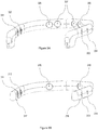
- FIG. 3A An example of a head-mounted frame is shown in figure. 3A .
- the T3 temporal electrodes at 301 and 302 are connected in parallel, providing fit for various head sizes by using a conductive insert in one electrode snap, and a non-conductive insert in the other snap.
- the T4 temporal electrodes at 303 and 304 are also connected in parallel. Small heads will have the conductive T3 and T4 inserts located at the front-most positions, and large heads will have the conductive inserts located at the rear-most positions.
- the FP1 frontal electrode is located at 305 , and the FP2 frontal electrode at 306 . Two ground electrodes are provided at 307 .
- a unique reference scheme is employed in this design: T3 is the reference signal for both FP1 and FP2 channels, and FP1 is the reference signal for both T3 and T4 channels. This design eliminates the need for a separate reference sensor.
- FIG. 3B An alternate embodiment of the head-mounted frame is shown in figure 3B .
- the frame is shorter at the rear ends to allow more clearance.
- Conductive rubber strips are added on the lower part of the frame at 317 and 318 to contact the tops of the ears.
- the T3 temporal electrodes at 311 and 312 , the T4 temporal electrodes at 313 and 314 , the FP1 frontal electrode at 315 , and the FP2 frontal electrode at 316 are located in the same positions as the first embodiment.
- the ground electrodes have been removed from the front of the frame, allowing better forehead contact to the FP1 and FP2 electrodes.
- the ground connection is now located at 317 , the conductive rubber strip contacting the top of the left ear.
- a primary electrical change in this embodiment is the addition of an independent reference connection at 318 , the conductive rubber strip contacting the top of the right ear.
- Each of the four channels, FP1, FP2, T3, and T4 are differential measurements with respect to the reference channel, to minimize common-mode signals.
- the measuring of electromagnetic energy of each sensor is charted into 11 subranges. Comparison between ranges of corresponding lobes indicates the degree of symmetry of that corresponding lobe and range. The greatest asymmetry is then indicated in real time and is used to indicate the range or ranges used as the range for mirroring the brain based on the dominant frequency in the middle range or ranges indicated. For example the middle range may be designated in subrange "7,” if the greatest asymmetry is in the lower frequency subranges, but may be designated in subrange "2 thru 3" if the greatest asymmetry is in an upper frequency range.
- subrange with the greatest asymmetry after determining the subrange with the greatest asymmetry, one could look to another predetermined subrange (e.g ., 4, 5, 6, 7, or 8), or groupings of subranges ( e.g ., 5-7 or 4-8) for the dominant frequencies for the source of input for the correlation with sounds that will be played when establishing rebalance.
- another predetermined subrange e.g ., 4, 5, 6, 7, or 8
- groupings of subranges e.g 5-7 or 4-8 for the dominant frequencies for the source of input for the correlation with sounds that will be played when establishing rebalance.
- Table 2 Example Subrange in Hz 1 2 3 4 5 6 7 8 9 10 11 1 0.1-0.5 .5-2 2-4 4-8 8-16 16-24 24-30 30-34 34-38 38-44 44-98 2 0.2-0.8 .8-2 2-5 5-10 10-15 15-20 20-25 25-30 30-36 36-46 36-96 3 0.4-1.2 1.2-3 3-6 6-12 12-18 18-24 24-30 30-35 35-40 40-45 45-95 4 0.5-1.5 1.5-3 3-7 7-12 12-18 18-25 25-32 32-39 39-46 46-49 49-99 5 0.8-1.8 1.8-4 4-10 10-16 16-24 24-30 30-36 36-42 42-48 48-62 62-98 6 0.9-2 2-4 4-7 7-11 11-16 16-22 22-28 28-35 35-43 43-52 52-92
Landscapes
- Health & Medical Sciences (AREA)
- Life Sciences & Earth Sciences (AREA)
- Engineering & Computer Science (AREA)
- General Health & Medical Sciences (AREA)
- Animal Behavior & Ethology (AREA)
- Veterinary Medicine (AREA)
- Biomedical Technology (AREA)
- Heart & Thoracic Surgery (AREA)
- Public Health (AREA)
- Physics & Mathematics (AREA)
- Molecular Biology (AREA)
- Surgery (AREA)
- Pathology (AREA)
- Medical Informatics (AREA)
- Biophysics (AREA)
- Psychology (AREA)
- Psychiatry (AREA)
- Anesthesiology (AREA)
- Hematology (AREA)
- Acoustics & Sound (AREA)
- Measurement And Recording Of Electrical Phenomena And Electrical Characteristics Of The Living Body (AREA)
- Artificial Intelligence (AREA)
- Computer Vision & Pattern Recognition (AREA)
- Physiology (AREA)
- Signal Processing (AREA)
Claims (14)
- System zur Wiederherstellung der Symmetrie in einem Gehirn, wobei das System umfasst:(a) eine Vorrichtung (210), wobei die Vorrichtung konfiguriert ist, um auf dem Kopf eines Benutzers zu ruhen und die Vorrichtung einen Satz von Kanälen umfasst, wobei der Satz von Kanälen umfasst:(i) ein erstes Paar von korrespondierenden Lappenkanälen, wobei das erste Paar von korrespondierenden Lappenkanälen einen rechten ersten Lappenkanal und einen linken ersten Lappenkanal umfasst, wobei der rechte erste Lappenkanal und der linke erste Lappenkanal auf gegenüberliegenden Hälften der Vorrichtung angeordnet sind, und(ii) ein zweites Paar von korrespondierenden Lappenkanälen, wobei das zweite Paar von korrespondierenden Lappenkanälen einen rechten zweiten Lappenkanal und einen linken zweiten Lappenkanal umfasst, wobei der rechte zweite Lappenkanal und der linke zweite Lappenkanal auf gegenüberliegenden Hälften der Vorrichtung angeordnet sind,wobei jeder Kanal mindestens einen Sensor (211, 212, 213, 214) umfasst und konfiguriert ist, um elektromagnetische Energie in einem Bereich eines Gehirns eines Benutzers zu messen und um eine Messung elektromagnetischer Energie zu erzeugen, wobei die Kanäle konfiguriert sind, um die elektromagnetische Energie gleichzeitig zu messen und das erste Paar von korrespondierenden Lappenkanälen konfiguriert ist, um elektromagnetische Energie von einem ersten Lappen zu messen, und das zweite Paar von korrespondierenden Lappenkanälen konfiguriert ist, um elektromagnetische Energie von einem zweiten Lappen zu messen, wobei der erste Lappen nicht derselbe wie der zweite Lappen ist;(b) ein Asymmetriebestimmungs-Computerprogrammprodukt, wobei das Asymmetriebestimmungs-Computerprogrammprodukt in einem konkreten Medium gespeichert ist und bei Anwendung bestimmt, ob während einer oder mehreren Zeitdauern eine Schwellendifferenz der Energie zwischen der Energie, die in einem oder mehreren eines ersten Teilbereichs gemessenen wird, einem zweiten Teilbereich von Frequenzen, und einem dritten Teilbereich von Frequenzen von einem rechten Lappenkanal vorliegt und in einem korrespondierenden Teilbereich eines korrespondierenden linken Lappenkanals, wobei der zweite Teilbereich aus Frequenzen besteht, die größer als die Frequenzen im ersten Teilbereich sind und der zweite Teilbereich aus Frequenzen besteht, die kleiner als die Frequenzen im dritten Teilbereich sind; und(c) eine zentrale Verarbeitungseinheit, wobei die zentrale Verarbeitung konfiguriert ist, um die Messungen der elektromagnetischen Aktivität von der Vorrichtung zu empfangen und das Asymmetriebestimmung-Computerprogrammprodukt auszuführen,(d) einen Sender, wobei der Sender ein oder mehrere Datenpakete drahtlos an die zentrale Verarbeitungseinheit senden kann, wobei jedes der einen oder mehreren Datenpakete Informationen umfasst, die der Messung elektromagnetischer Energie entsprechen, und die zentrale Verarbeitungseinheit eine Datennachricht erzeugen kann, wobei die Datennachricht Informationen enthält, die eine Beobachtung einer Material-Aktivitätsasymmetrie zwischen einem oder beiden der folgenden Elemente anzeigen:(i) den Messungen von einem Teilbereich des rechten ersten Lappenkanals und den Messungen eines korrespondierenden Teilbereichs des linken ersten Lappenkanals; und(ii) den Messungen von einem Teilbereich des rechten zweiten Lappenkanals und der Messungen eines korrespondierenden Teilbereichs des linken zweiten Lappenkanals,wobei die Vorrichtung weiter mindestens einen Lautsprecher (190) umfasst und das System weiter umfasst:(e) einen Korrelationsalgorithmus, wobei der Korrelationsalgorithmus jede einer Vielzahl von Frequenzen aus einem Satz von Gehirnwellenfrequenzen mit einem akustischen Stimulus korreliert; und(f) ein Wiedergabe-Computerprogrammprodukt, wobei das Wiedergabe-Computerprogrammprodukt auf einem konkreten Medium gespeichert und so konfiguriert ist, dasswobei das Asymmetriebestimmungs-Computerprogrammprodukt weiter konfiguriert ist, um die Lappen dynamisch zu schalten, von denen das Asymmetriebestimmungs-Computerprogrammprodukt die dominanten Frequenzen beim Auftreten eines Auslöseereignisses erhält.(i)(a) wenn es eine wesentliche Material-Aktivitätsasymmetrie zwischen den Messungen aus einem Teilbereich von Frequenzen entweder des rechten ersten Lappenkanals und des linken ersten Lappenkanals oder des rechten zweiten Lappenkanals und des linken zweiten Lappenkanals gibt, das Computerprogrammprodukt eine Vielzahl von Gehirnwellen mit dominanter Frequenz aus dem zweiten Teilbereich der Lappen, für die die Materialasymmetrie vorliegt, in akustische Reize übersetzt; und(b) wenn es keine wesentliche Material-Aktivitätsasymmetrie zwischen den Messungen aus einem Teilbereich von Frequenzen entweder des rechten ersten Lappenkanals und des linken ersten Lappenkanals oder des rechten zweiten Lappenkanals und des linken zweiten Lappenkanals gibt, das Computerprogrammprodukt eine Vielzahl von Gehirnwellen mit dominanter Frequenz aus dem zweiten Teilbereich von entweder dem ersten Satz von Lappenkanälen oder dem zweiten Satz von Lappenkanälen in akustische Reize zu übersetzt; und(ii) das Wiedergabe-Computerprogrammprodukt das Wiedergeben der akustischen Reize durch den mindestens einen Lautsprecher steuert, wobei die akustischen Reize einen Echtzeitspiegel der Vielzahl von Gehirnwellen mit domanter Frequenz aus dem zweiten Teilbereich bereitstellen, und
- System nach Anspruch 1, wobei der mindestens eine Lautsprecher (190) einen rechten Lautsprecher und einen linken Lautsprecher umfasst und der rechte Lautsprecher konfiguriert ist, um sich am oder nahe dem rechten Ohr des Benutzers zu befinden, und der linke Lautsprecher konfiguriert ist, um sich am oder nahe dem linken Ohr des Benutzers zu befinden, wenn die Vorrichtung verwendet wird.
- System nach Anspruch 1 oder Anspruch 2, wobei der rechte erste Lappenkanal positioniert ist, um elektromagnetische Energie von dem rechten Frontallappen zu messen, der linke erste Lappenkanal positioniert ist, um elektromagnetische Energie von der linken Frontallappen zu messen, der rechte zweite Lappenkanal positioniert ist, um elektromagnetische Energie von dem rechten Temporallappen zu messen, und der linke zweite Lappenkanal positioniert ist, um elektromagnetische Energie von dem linken Temporallappen zu messen;
das System optional weiter einen Referenzsensor (215) umfassend. - System nach einem der Ansprüche 1 bis 3, wobei das System konfiguriert ist, um Daten bis zu mindestens 1000 Proben pro Sekunde zu verarbeiten;
optional, wobei das System konfiguriert ist, um Energie entlang einer Außenfläche jedes Sensors zu liefern und Impedanz zu messen. - System nach einem der Ansprüche 1 bis 4, wobei das Auslöseereignis eine vorbestimmte Zunahme einer Energiedifferenz zwischen Energien ist, die innerhalb eines oder mehrerer eines ersten Teilbereichs von Frequenzen, eines zweiten Teilbereichs von Frequenzen und eines dritten Teilbereichs von Frequenzen gemessen werden.
- System nach einem der Ansprüche 1 bis 4, wobei das Auslöseereignis eine vorbestimmte Abnahme einer Energiedifferenz zwischen Energien ist, die innerhalb eines oder mehrerer eines ersten Teilbereichs von Frequenzen, eines zweiten Teilbereichs von Frequenzen und eines dritten Teilbereichs von Frequenzen gemessen werden.
- System nach einem der Ansprüche 1 bis 6, wobei das Asymmetriebestimmungs-Computerprogrammprodukt konfiguriert ist, um zu bestimmen, ob es eine Schwellendifferenz in der Energie gibt, indem eine berechnete Energie der Frequenzen innerhalb jedes Teilbereichs vom rechten ersten Lappenkanal mit einer berechneten Energie der Frequenzen des entsprechenden Teilbereichs vom linken ersten Lappenkanal über eine vorbestimmte Zeitdauer verglichen wird.
- System nach einem der Ansprüche 1 bis 6, wobei das Asymmetriebestimmungs-Computerprogrammprodukt konfiguriert ist, um zu bestimmen, ob es eine Schwellendifferenz in der Energie gibt, indem eine berechnete Energie der Frequenzen innerhalb jedes Teilbereichs vom rechten ersten Lappenkanal mit einer berechneten Energie der Frequenzen innerhalb jedes Teilbereichs vom linken ersten Lappenkanal über eine Vielzahl von vorbestimmten Zeitdauern verglichen wird;
optional wobei vorbestimmte Zeitdauern sich überlappen. - System nach einem der Ansprüche 1 bis 8, wobei die Vorrichtung als Stirnband konfiguriert ist, wobei das Stirnband die Form eines Visiers hat, das sich im Gebrauch von Ohr zu Ohr über die Stirn erstreckt.
- System nach einem der Ansprüche 1 bis 8, wobei die Vorrichtung als ein Hut oder Helm konfiguriert ist.
- System nach einem der Ansprüche 1 bis 10, wobei die Vorrichtung weiter eine Datenspeichereinheit umfasst, wobei die Datenspeichereinheit konfiguriert ist, um Messungen von elektromagnetischer Energie zu speichern.
- System nach einem der Ansprüche 1 bis 11, wobei die Schwellendifferenz in der Energie zwischen gemessenen Energien für jede einer Vielzahl von Epochen bestimmt wird, wobei jede Epoche im Bereich von 5 bis 30 Sekunden liegt.
- System nach Anspruch 12, wobei Messungen der Schwellendifferenz in der Energie mit einer Rate von 500 Proben pro Sekunde durchgeführt werden.
- System nach Anspruch 13, wobei die Kanäle konfiguriert sind, um Frequenzen bis zu ungefähr 100 Hertz zu messen.
Applications Claiming Priority (3)
| Application Number | Priority Date | Filing Date | Title |
|---|---|---|---|
| US201562207233P | 2015-08-19 | 2015-08-19 | |
| US201562242673P | 2015-10-16 | 2015-10-16 | |
| PCT/US2016/046970 WO2017031028A1 (en) | 2015-08-19 | 2016-08-15 | Devices, systems and methods for monitoring brain activity and for enabling brain to rebalance |
Publications (3)
| Publication Number | Publication Date |
|---|---|
| EP3337395A1 EP3337395A1 (de) | 2018-06-27 |
| EP3337395A4 EP3337395A4 (de) | 2019-04-17 |
| EP3337395B1 true EP3337395B1 (de) | 2019-10-16 |
Family
ID=58051424
Family Applications (1)
| Application Number | Title | Priority Date | Filing Date |
|---|---|---|---|
| EP16837629.1A Active EP3337395B1 (de) | 2015-08-19 | 2016-08-15 | System zur überwachung der gehirnaktivität und zur ermöglichung, das gehirn wieder ins gleichgewicht zu bringen |
Country Status (5)
| Country | Link |
|---|---|
| US (1) | US10029067B2 (de) |
| EP (1) | EP3337395B1 (de) |
| CA (1) | CA2993636C (de) |
| DK (1) | DK3337395T3 (de) |
| WO (1) | WO2017031028A1 (de) |
Families Citing this family (10)
| Publication number | Priority date | Publication date | Assignee | Title |
|---|---|---|---|---|
| WO2017031028A1 (en) | 2015-08-19 | 2017-02-23 | Brain State Technologies, Llc | Devices, systems and methods for monitoring brain activity and for enabling brain to rebalance |
| US10532183B2 (en) * | 2017-09-06 | 2020-01-14 | Arenar Group B.V. | Sleep improvement device and method for improving sleep |
| US10866638B2 (en) * | 2018-03-23 | 2020-12-15 | Abl Ip Holding Llc | Neural control of controllable device |
| US10682069B2 (en) * | 2018-03-23 | 2020-06-16 | Abl Ip Holding Llc | User preference and user hierarchy in an electroencephalography based control system |
| US10551921B2 (en) * | 2018-03-23 | 2020-02-04 | Abl Ip Holding Llc | Electroencephalography control of controllable device |
| US10682099B2 (en) * | 2018-03-23 | 2020-06-16 | Abl Ip Holding Llc | Training of an electroencephalography based control system |
| EP3972687B1 (de) * | 2019-05-21 | 2024-04-24 | Brain State Technologies, LLC | Rebalance des gehirns durch akustische und elektrische spiegelung |
| US11786694B2 (en) | 2019-05-24 | 2023-10-17 | NeuroLight, Inc. | Device, method, and app for facilitating sleep |
| KR20210074601A (ko) * | 2019-12-12 | 2021-06-22 | 현대자동차주식회사 | 뇌파 신호를 이용한 긴급 주행 상황 제어 장치 및 방법 |
| TWI819919B (zh) * | 2022-12-08 | 2023-10-21 | 國立陽明交通大學 | 過動症早期輔助診斷系統 |
Family Cites Families (13)
| Publication number | Priority date | Publication date | Assignee | Title |
|---|---|---|---|---|
| US7460903B2 (en) | 2002-07-25 | 2008-12-02 | Pineda Jaime A | Method and system for a real time adaptive system for effecting changes in cognitive-emotive profiles |
| US20060116600A1 (en) * | 2004-11-30 | 2006-06-01 | Vesely Michael A | Brain balancing by binaural beat |
| US20070185533A1 (en) | 2006-02-03 | 2007-08-09 | Brainstate Technologies, Inc. | Neurofeedback conditioning method |
| US8249699B2 (en) * | 2006-02-03 | 2012-08-21 | Brain State Technologies, Llc | Method of affecting balanced brain function with relational ambient sound |
| CA2969849C (en) | 2007-03-27 | 2019-04-30 | Dignity Health | Urgent eeg net with transmission capabilities |
| US8244341B2 (en) | 2007-08-23 | 2012-08-14 | Tallinn University Of Technology | Method and device for determining depressive disorders by measuring bioelectromagnetic signals of the brain |
| US8239030B1 (en) | 2010-01-06 | 2012-08-07 | DJ Technologies | Transcranial stimulation device and method based on electrophysiological testing |
| US20140058189A1 (en) | 2012-02-20 | 2014-02-27 | William F. Stubbeman | Systems and methods using brain stimulation for treating disorders |
| US9427581B2 (en) | 2013-04-28 | 2016-08-30 | ElectroCore, LLC | Devices and methods for treating medical disorders with evoked potentials and vagus nerve stimulation |
| US9265943B2 (en) | 2013-09-13 | 2016-02-23 | Ybrain Inc. | Method for stimulating living body more accurately and apparatus using the same |
| WO2015131093A1 (en) | 2014-02-27 | 2015-09-03 | Thync, Inc. | Methods and apparatuses for user control of neurostimulation |
| TWM488322U (zh) | 2014-03-14 | 2014-10-21 | Contour Optik Inc | 跨顱電刺激裝置 |
| WO2017031028A1 (en) | 2015-08-19 | 2017-02-23 | Brain State Technologies, Llc | Devices, systems and methods for monitoring brain activity and for enabling brain to rebalance |
-
2016
- 2016-08-15 WO PCT/US2016/046970 patent/WO2017031028A1/en not_active Ceased
- 2016-08-15 EP EP16837629.1A patent/EP3337395B1/de active Active
- 2016-08-15 DK DK16837629.1T patent/DK3337395T3/da active
- 2016-08-15 US US15/550,200 patent/US10029067B2/en active Active
- 2016-08-15 CA CA2993636A patent/CA2993636C/en active Active
Non-Patent Citations (1)
| Title |
|---|
| None * |
Also Published As
| Publication number | Publication date |
|---|---|
| US10029067B2 (en) | 2018-07-24 |
| US20180154104A1 (en) | 2018-06-07 |
| CA2993636C (en) | 2022-06-14 |
| EP3337395A4 (de) | 2019-04-17 |
| WO2017031028A1 (en) | 2017-02-23 |
| DK3337395T3 (da) | 2020-01-13 |
| EP3337395A1 (de) | 2018-06-27 |
| CA2993636A1 (en) | 2017-02-23 |
Similar Documents
| Publication | Publication Date | Title |
|---|---|---|
| EP3337395B1 (de) | System zur überwachung der gehirnaktivität und zur ermöglichung, das gehirn wieder ins gleichgewicht zu bringen | |
| Billings et al. | Predicting perception in noise using cortical auditory evoked potentials | |
| Krause et al. | Effects of electromagnetic field emitted by cellular phones on the EEG during an auditory memory task: a double blind replication study | |
| CN110947076B (zh) | 一种可进行精神状态调节的智能脑波音乐可穿戴设备 | |
| Cartocci et al. | Mental workload estimations in unilateral deafened children | |
| GB2608690A (en) | Personalized mental state adjustment system and method based on brainwave music | |
| ES2763851T3 (es) | Procedimiento para la cuantificación de la capacidad cognitiva de una persona | |
| Looney et al. | Ear-EEG: user-centered and wearable BCI | |
| US12023222B2 (en) | Vestibular stimulation device, dizziness treatment device, and health promotion device | |
| CN110051347A (zh) | 一种用户睡眠检测方法及系统 | |
| Crum | Hearables: Here come the: Technology tucked inside your ears will augment your daily life | |
| Bellier et al. | Speech auditory brainstem response through hearing aid stimulation | |
| Easwar et al. | Phase‐locked responses to the vowel envelope vary in scalp‐recorded amplitude due to across‐frequency response interactions | |
| KR102140834B1 (ko) | 개인 청력상태에 따른 이명 자가 치료 시스템 | |
| MacDougall et al. | μVEMP: a portable interface to record vestibular evoked myogenic potentials (VEMPs) with a smart phone or tablet | |
| Tseng et al. | Comparison of bone-conducted vibration for eliciting ocular vestibular-evoked myogenic potentials: forehead versus mastoid tapping | |
| Han et al. | Noise-induced change of cortical temporal processing in cochlear implant users | |
| Ferracuti et al. | Auditory paradigm for a P300 BCI system using spatial hearing | |
| CN103099625B (zh) | 一种听觉时间调制传递函数的测试方法及系统 | |
| EP3972687B1 (de) | Rebalance des gehirns durch akustische und elektrische spiegelung | |
| Jarollahi et al. | Sound-field speech evoked auditory brainstem response in cochlear-implant recipients | |
| KR20210020314A (ko) | 비교 소리의 인지 반응 평가 장치 및 방법 | |
| Thornton et al. | Comparison of linear and nonlinear methods for decoding selective attention to speech from ear-EEG recordings | |
| Abrams et al. | Rapid acoustic processing in the auditory brainstem is not related to cortical asymmetry for the syllable rate of speech | |
| Comoglio et al. | Real-life ear-EEG Recordings of Auditory Responses to Ambient Sounds |
Legal Events
| Date | Code | Title | Description |
|---|---|---|---|
| STAA | Information on the status of an ep patent application or granted ep patent |
Free format text: STATUS: THE INTERNATIONAL PUBLICATION HAS BEEN MADE |
|
| PUAI | Public reference made under article 153(3) epc to a published international application that has entered the european phase |
Free format text: ORIGINAL CODE: 0009012 |
|
| STAA | Information on the status of an ep patent application or granted ep patent |
Free format text: STATUS: REQUEST FOR EXAMINATION WAS MADE |
|
| 17P | Request for examination filed |
Effective date: 20180126 |
|
| AK | Designated contracting states |
Kind code of ref document: A1 Designated state(s): AL AT BE BG CH CY CZ DE DK EE ES FI FR GB GR HR HU IE IS IT LI LT LU LV MC MK MT NL NO PL PT RO RS SE SI SK SM TR |
|
| AX | Request for extension of the european patent |
Extension state: BA ME |
|
| DAV | Request for validation of the european patent (deleted) | ||
| DAX | Request for extension of the european patent (deleted) | ||
| A4 | Supplementary search report drawn up and despatched |
Effective date: 20190315 |
|
| RIC1 | Information provided on ipc code assigned before grant |
Ipc: A61B 5/16 20060101ALN20190311BHEP Ipc: A61B 5/04 20060101AFI20190311BHEP Ipc: A61B 5/0482 20060101ALI20190311BHEP Ipc: A61B 5/00 20060101ALI20190311BHEP Ipc: A61N 1/08 20060101ALI20190311BHEP |
|
| GRAP | Despatch of communication of intention to grant a patent |
Free format text: ORIGINAL CODE: EPIDOSNIGR1 |
|
| STAA | Information on the status of an ep patent application or granted ep patent |
Free format text: STATUS: GRANT OF PATENT IS INTENDED |
|
| RIC1 | Information provided on ipc code assigned before grant |
Ipc: A61B 5/0482 20060101ALI20190620BHEP Ipc: A61B 5/00 20060101ALI20190620BHEP Ipc: A61B 5/04 20060101AFI20190620BHEP Ipc: A61N 1/08 20060101ALI20190620BHEP Ipc: A61B 5/16 20060101ALN20190620BHEP |
|
| INTG | Intention to grant announced |
Effective date: 20190723 |
|
| GRAS | Grant fee paid |
Free format text: ORIGINAL CODE: EPIDOSNIGR3 |
|
| GRAA | (expected) grant |
Free format text: ORIGINAL CODE: 0009210 |
|
| STAA | Information on the status of an ep patent application or granted ep patent |
Free format text: STATUS: THE PATENT HAS BEEN GRANTED |
|
| AK | Designated contracting states |
Kind code of ref document: B1 Designated state(s): AL AT BE BG CH CY CZ DE DK EE ES FI FR GB GR HR HU IE IS IT LI LT LU LV MC MK MT NL NO PL PT RO RS SE SI SK SM TR |
|
| REG | Reference to a national code |
Ref country code: GB Ref legal event code: FG4D |
|
| REG | Reference to a national code |
Ref country code: CH Ref legal event code: EP |
|
| REG | Reference to a national code |
Ref country code: DE Ref legal event code: R096 Ref document number: 602016022716 Country of ref document: DE |
|
| REG | Reference to a national code |
Ref country code: IE Ref legal event code: FG4D |
|
| REG | Reference to a national code |
Ref country code: AT Ref legal event code: REF Ref document number: 1190494 Country of ref document: AT Kind code of ref document: T Effective date: 20191115 |
|
| REG | Reference to a national code |
Ref country code: CH Ref legal event code: NV Representative=s name: VENI GMBH, CH |
|
| REG | Reference to a national code |
Ref country code: DK Ref legal event code: T3 Effective date: 20200107 |
|
| REG | Reference to a national code |
Ref country code: NL Ref legal event code: MP Effective date: 20191016 |
|
| REG | Reference to a national code |
Ref country code: LT Ref legal event code: MG4D |
|
| REG | Reference to a national code |
Ref country code: AT Ref legal event code: MK05 Ref document number: 1190494 Country of ref document: AT Kind code of ref document: T Effective date: 20191016 |
|
| PG25 | Lapsed in a contracting state [announced via postgrant information from national office to epo] |
Ref country code: NO Free format text: LAPSE BECAUSE OF FAILURE TO SUBMIT A TRANSLATION OF THE DESCRIPTION OR TO PAY THE FEE WITHIN THE PRESCRIBED TIME-LIMIT Effective date: 20200116 Ref country code: GR Free format text: LAPSE BECAUSE OF FAILURE TO SUBMIT A TRANSLATION OF THE DESCRIPTION OR TO PAY THE FEE WITHIN THE PRESCRIBED TIME-LIMIT Effective date: 20200117 Ref country code: SE Free format text: LAPSE BECAUSE OF FAILURE TO SUBMIT A TRANSLATION OF THE DESCRIPTION OR TO PAY THE FEE WITHIN THE PRESCRIBED TIME-LIMIT Effective date: 20191016 Ref country code: LV Free format text: LAPSE BECAUSE OF FAILURE TO SUBMIT A TRANSLATION OF THE DESCRIPTION OR TO PAY THE FEE WITHIN THE PRESCRIBED TIME-LIMIT Effective date: 20191016 Ref country code: AT Free format text: LAPSE BECAUSE OF FAILURE TO SUBMIT A TRANSLATION OF THE DESCRIPTION OR TO PAY THE FEE WITHIN THE PRESCRIBED TIME-LIMIT Effective date: 20191016 Ref country code: PT Free format text: LAPSE BECAUSE OF FAILURE TO SUBMIT A TRANSLATION OF THE DESCRIPTION OR TO PAY THE FEE WITHIN THE PRESCRIBED TIME-LIMIT Effective date: 20200217 Ref country code: FI Free format text: LAPSE BECAUSE OF FAILURE TO SUBMIT A TRANSLATION OF THE DESCRIPTION OR TO PAY THE FEE WITHIN THE PRESCRIBED TIME-LIMIT Effective date: 20191016 Ref country code: BG Free format text: LAPSE BECAUSE OF FAILURE TO SUBMIT A TRANSLATION OF THE DESCRIPTION OR TO PAY THE FEE WITHIN THE PRESCRIBED TIME-LIMIT Effective date: 20200116 Ref country code: NL Free format text: LAPSE BECAUSE OF FAILURE TO SUBMIT A TRANSLATION OF THE DESCRIPTION OR TO PAY THE FEE WITHIN THE PRESCRIBED TIME-LIMIT Effective date: 20191016 Ref country code: LT Free format text: LAPSE BECAUSE OF FAILURE TO SUBMIT A TRANSLATION OF THE DESCRIPTION OR TO PAY THE FEE WITHIN THE PRESCRIBED TIME-LIMIT Effective date: 20191016 Ref country code: PL Free format text: LAPSE BECAUSE OF FAILURE TO SUBMIT A TRANSLATION OF THE DESCRIPTION OR TO PAY THE FEE WITHIN THE PRESCRIBED TIME-LIMIT Effective date: 20191016 |
|
| PG25 | Lapsed in a contracting state [announced via postgrant information from national office to epo] |
Ref country code: HR Free format text: LAPSE BECAUSE OF FAILURE TO SUBMIT A TRANSLATION OF THE DESCRIPTION OR TO PAY THE FEE WITHIN THE PRESCRIBED TIME-LIMIT Effective date: 20191016 Ref country code: RS Free format text: LAPSE BECAUSE OF FAILURE TO SUBMIT A TRANSLATION OF THE DESCRIPTION OR TO PAY THE FEE WITHIN THE PRESCRIBED TIME-LIMIT Effective date: 20191016 Ref country code: IS Free format text: LAPSE BECAUSE OF FAILURE TO SUBMIT A TRANSLATION OF THE DESCRIPTION OR TO PAY THE FEE WITHIN THE PRESCRIBED TIME-LIMIT Effective date: 20200224 |
|
| PG25 | Lapsed in a contracting state [announced via postgrant information from national office to epo] |
Ref country code: AL Free format text: LAPSE BECAUSE OF FAILURE TO SUBMIT A TRANSLATION OF THE DESCRIPTION OR TO PAY THE FEE WITHIN THE PRESCRIBED TIME-LIMIT Effective date: 20191016 |
|
| REG | Reference to a national code |
Ref country code: DE Ref legal event code: R097 Ref document number: 602016022716 Country of ref document: DE |
|
| PG2D | Information on lapse in contracting state deleted |
Ref country code: IS |
|
| PG25 | Lapsed in a contracting state [announced via postgrant information from national office to epo] |
Ref country code: IS Free format text: LAPSE BECAUSE OF FAILURE TO SUBMIT A TRANSLATION OF THE DESCRIPTION OR TO PAY THE FEE WITHIN THE PRESCRIBED TIME-LIMIT Effective date: 20200216 Ref country code: EE Free format text: LAPSE BECAUSE OF FAILURE TO SUBMIT A TRANSLATION OF THE DESCRIPTION OR TO PAY THE FEE WITHIN THE PRESCRIBED TIME-LIMIT Effective date: 20191016 Ref country code: ES Free format text: LAPSE BECAUSE OF FAILURE TO SUBMIT A TRANSLATION OF THE DESCRIPTION OR TO PAY THE FEE WITHIN THE PRESCRIBED TIME-LIMIT Effective date: 20191016 Ref country code: CZ Free format text: LAPSE BECAUSE OF FAILURE TO SUBMIT A TRANSLATION OF THE DESCRIPTION OR TO PAY THE FEE WITHIN THE PRESCRIBED TIME-LIMIT Effective date: 20191016 Ref country code: RO Free format text: LAPSE BECAUSE OF FAILURE TO SUBMIT A TRANSLATION OF THE DESCRIPTION OR TO PAY THE FEE WITHIN THE PRESCRIBED TIME-LIMIT Effective date: 20191016 |
|
| PLBE | No opposition filed within time limit |
Free format text: ORIGINAL CODE: 0009261 |
|
| STAA | Information on the status of an ep patent application or granted ep patent |
Free format text: STATUS: NO OPPOSITION FILED WITHIN TIME LIMIT |
|
| PG25 | Lapsed in a contracting state [announced via postgrant information from national office to epo] |
Ref country code: IT Free format text: LAPSE BECAUSE OF FAILURE TO SUBMIT A TRANSLATION OF THE DESCRIPTION OR TO PAY THE FEE WITHIN THE PRESCRIBED TIME-LIMIT Effective date: 20191016 Ref country code: SM Free format text: LAPSE BECAUSE OF FAILURE TO SUBMIT A TRANSLATION OF THE DESCRIPTION OR TO PAY THE FEE WITHIN THE PRESCRIBED TIME-LIMIT Effective date: 20191016 Ref country code: SK Free format text: LAPSE BECAUSE OF FAILURE TO SUBMIT A TRANSLATION OF THE DESCRIPTION OR TO PAY THE FEE WITHIN THE PRESCRIBED TIME-LIMIT Effective date: 20191016 |
|
| 26N | No opposition filed |
Effective date: 20200717 |
|
| REG | Reference to a national code |
Ref country code: DE Ref legal event code: R079 Ref document number: 602016022716 Country of ref document: DE Free format text: PREVIOUS MAIN CLASS: A61B0005040000 Ipc: A61B0005240000 |
|
| PG25 | Lapsed in a contracting state [announced via postgrant information from national office to epo] |
Ref country code: SI Free format text: LAPSE BECAUSE OF FAILURE TO SUBMIT A TRANSLATION OF THE DESCRIPTION OR TO PAY THE FEE WITHIN THE PRESCRIBED TIME-LIMIT Effective date: 20191016 |
|
| PG25 | Lapsed in a contracting state [announced via postgrant information from national office to epo] |
Ref country code: MC Free format text: LAPSE BECAUSE OF FAILURE TO SUBMIT A TRANSLATION OF THE DESCRIPTION OR TO PAY THE FEE WITHIN THE PRESCRIBED TIME-LIMIT Effective date: 20191016 |
|
| PG25 | Lapsed in a contracting state [announced via postgrant information from national office to epo] |
Ref country code: LU Free format text: LAPSE BECAUSE OF NON-PAYMENT OF DUE FEES Effective date: 20200815 |
|
| REG | Reference to a national code |
Ref country code: BE Ref legal event code: MM Effective date: 20200831 |
|
| PG25 | Lapsed in a contracting state [announced via postgrant information from national office to epo] |
Ref country code: IE Free format text: LAPSE BECAUSE OF NON-PAYMENT OF DUE FEES Effective date: 20200815 Ref country code: BE Free format text: LAPSE BECAUSE OF NON-PAYMENT OF DUE FEES Effective date: 20200831 |
|
| PG25 | Lapsed in a contracting state [announced via postgrant information from national office to epo] |
Ref country code: TR Free format text: LAPSE BECAUSE OF FAILURE TO SUBMIT A TRANSLATION OF THE DESCRIPTION OR TO PAY THE FEE WITHIN THE PRESCRIBED TIME-LIMIT Effective date: 20191016 Ref country code: MT Free format text: LAPSE BECAUSE OF FAILURE TO SUBMIT A TRANSLATION OF THE DESCRIPTION OR TO PAY THE FEE WITHIN THE PRESCRIBED TIME-LIMIT Effective date: 20191016 Ref country code: CY Free format text: LAPSE BECAUSE OF FAILURE TO SUBMIT A TRANSLATION OF THE DESCRIPTION OR TO PAY THE FEE WITHIN THE PRESCRIBED TIME-LIMIT Effective date: 20191016 |
|
| PG25 | Lapsed in a contracting state [announced via postgrant information from national office to epo] |
Ref country code: MK Free format text: LAPSE BECAUSE OF FAILURE TO SUBMIT A TRANSLATION OF THE DESCRIPTION OR TO PAY THE FEE WITHIN THE PRESCRIBED TIME-LIMIT Effective date: 20191016 |
|
| PGFP | Annual fee paid to national office [announced via postgrant information from national office to epo] |
Ref country code: DK Payment date: 20250825 Year of fee payment: 10 Ref country code: DE Payment date: 20250827 Year of fee payment: 10 |
|
| PGFP | Annual fee paid to national office [announced via postgrant information from national office to epo] |
Ref country code: GB Payment date: 20250827 Year of fee payment: 10 |
|
| PGFP | Annual fee paid to national office [announced via postgrant information from national office to epo] |
Ref country code: FR Payment date: 20250825 Year of fee payment: 10 |
|
| PGFP | Annual fee paid to national office [announced via postgrant information from national office to epo] |
Ref country code: CH Payment date: 20250901 Year of fee payment: 10 |