EP3337633B1 - Methode et appareil pour soudage par impulsion - Google Patents
Methode et appareil pour soudage par impulsion Download PDFInfo
- Publication number
- EP3337633B1 EP3337633B1 EP16781883.0A EP16781883A EP3337633B1 EP 3337633 B1 EP3337633 B1 EP 3337633B1 EP 16781883 A EP16781883 A EP 16781883A EP 3337633 B1 EP3337633 B1 EP 3337633B1
- Authority
- EP
- European Patent Office
- Prior art keywords
- transition
- voltage
- module
- output
- welding
- Prior art date
- Legal status (The legal status is an assumption and is not a legal conclusion. Google has not performed a legal analysis and makes no representation as to the accuracy of the status listed.)
- Active
Links
Images



Classifications
-
- B—PERFORMING OPERATIONS; TRANSPORTING
- B23—MACHINE TOOLS; METAL-WORKING NOT OTHERWISE PROVIDED FOR
- B23K—SOLDERING OR UNSOLDERING; WELDING; CLADDING OR PLATING BY SOLDERING OR WELDING; CUTTING BY APPLYING HEAT LOCALLY, e.g. FLAME CUTTING; WORKING BY LASER BEAM
- B23K9/00—Arc welding or cutting
- B23K9/09—Arrangements or circuits for arc welding with pulsed current or voltage
- B23K9/091—Arrangements or circuits for arc welding with pulsed current or voltage characterised by the circuits
- B23K9/092—Arrangements or circuits for arc welding with pulsed current or voltage characterised by the circuits characterised by the shape of the pulses produced
-
- B—PERFORMING OPERATIONS; TRANSPORTING
- B23—MACHINE TOOLS; METAL-WORKING NOT OTHERWISE PROVIDED FOR
- B23K—SOLDERING OR UNSOLDERING; WELDING; CLADDING OR PLATING BY SOLDERING OR WELDING; CUTTING BY APPLYING HEAT LOCALLY, e.g. FLAME CUTTING; WORKING BY LASER BEAM
- B23K9/00—Arc welding or cutting
- B23K9/09—Arrangements or circuits for arc welding with pulsed current or voltage
- B23K9/091—Arrangements or circuits for arc welding with pulsed current or voltage characterised by the circuits
-
- B—PERFORMING OPERATIONS; TRANSPORTING
- B23—MACHINE TOOLS; METAL-WORKING NOT OTHERWISE PROVIDED FOR
- B23K—SOLDERING OR UNSOLDERING; WELDING; CLADDING OR PLATING BY SOLDERING OR WELDING; CUTTING BY APPLYING HEAT LOCALLY, e.g. FLAME CUTTING; WORKING BY LASER BEAM
- B23K9/00—Arc welding or cutting
- B23K9/09—Arrangements or circuits for arc welding with pulsed current or voltage
- B23K9/091—Arrangements or circuits for arc welding with pulsed current or voltage characterised by the circuits
- B23K9/093—Arrangements or circuits for arc welding with pulsed current or voltage characterised by the circuits the frequency of the pulses produced being modulable
-
- B—PERFORMING OPERATIONS; TRANSPORTING
- B23—MACHINE TOOLS; METAL-WORKING NOT OTHERWISE PROVIDED FOR
- B23K—SOLDERING OR UNSOLDERING; WELDING; CLADDING OR PLATING BY SOLDERING OR WELDING; CUTTING BY APPLYING HEAT LOCALLY, e.g. FLAME CUTTING; WORKING BY LASER BEAM
- B23K9/00—Arc welding or cutting
- B23K9/095—Monitoring or automatic control of welding parameters
- B23K9/0953—Monitoring or automatic control of welding parameters using computing means
-
- B—PERFORMING OPERATIONS; TRANSPORTING
- B23—MACHINE TOOLS; METAL-WORKING NOT OTHERWISE PROVIDED FOR
- B23K—SOLDERING OR UNSOLDERING; WELDING; CLADDING OR PLATING BY SOLDERING OR WELDING; CUTTING BY APPLYING HEAT LOCALLY, e.g. FLAME CUTTING; WORKING BY LASER BEAM
- B23K9/00—Arc welding or cutting
- B23K9/10—Other electric circuits therefor; Protective circuits; Remote controls
- B23K9/1006—Power supply
Definitions
- the present invention relates generally to the art of welding and welding power supplies. More specifically, it relates to a welding-type system and a method of providing welding-type power as shown in the preamble of claims 1 and 9 (see, for example, US,8,704,131 B2 ).
- Welding type system or system for providing welding type power, as used herein, includes one or more of a power source, controller, wire feeder, and a source of gas, it may also include peripherals such as robots etc., that cooperate to provide welding type power.
- Welding power supply includes any device capable of supplying welding, plasma cutting, and/or induction heating power including power circuitry, control circuitry and other ancillary circuitry associated therewith.
- Welding-type power is power suitable for welding, induction heating or plasma cutting.
- a current controlled (or controlled current) welding power source is a power source wherein the output current is monitored, and the output is adjusted to provide the desired current.
- the current may be constant during the welding process, or may have a desired waveform of varying current.
- Current controlled (or controlled current) welding power is an output wherein the current is monitored and adjusted to provide the desired current.
- a voltage controlled (or controlled voltage) power source is a power source wherein the output voltage is monitored, and the output is adjusted to provide the desired voltage.
- the voltage may be constant during the welding process, or may have a desired waveform of varying voltage.
- Voltage controlled (or controlled voltage) welding power is an output wherein the voltage is monitored and adjusted to provide the desired current.
- a pulsed MIG process typically has a cyclical output having at least a peak portion with a relatively high current and a background portion with a relatively low current.
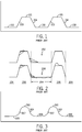
- a typical prior art pulsed MIG welding cycle is shown in Figure 1 , and includes a flat peak 101, a background 102, and steep transitions 103 and 104 between them. There is often an abrupt change in slope from the beginning and end of the peak and background portions.
- Pulse welding includes welding with output power that is generally pulsed, at a controllable frequency, between a greater peak and a lesser background, and pulse welding is performed in an arc state. Occasional, inadvertent shorts may occur, but the process is generally in an arc state.
- Welding cycle (or pulse cycle), as used herein, is comprised of at least a peak, followed by a transition down, followed by a background, followed by a transition up. Welding cycles are typically on the order of milliseconds or tens of milliseconds. Welding cycles can include other portions as well, and a controller can use a state based control scheme where, under certain circumstance, the typical order (peak, down, background, up) is not followed.
- Short circuit MIG welding typically transfers in a short condition (short circuit welding).
- Spray MIG welding continuously sprays balls (spray mode) across the arc (typically without intentionally shorting to the weld puddle).
- the molten ball is transferred at any time during the process (when a short occurs or when there is sufficient ball size and arc force for spray mode).
- Short circuit MIG welding typically has a single voltage target, not a defined waveform, with a control loop to maintain and average voltage (not a defined waveform). This is different from pulse welding which typically begins (and sometimes finishes the molten ball transfer) while in an arc condition.
- the molten ball is typically transferred during or shortly after the peak (the time of transfer is controlled by the waveform).
- pulse welding has multiple output targets, including CV ramping, peak and background portions, and follows a defined voltage/current waveform The embodiments below will be described with respect to pulse welding.
- Undesirable audible arc noise is generated by the sharp edges in the pulse waveform of Figure 1 .
- the sharp slope changes can cause difficulty when welding with specialty wires such as Inconel®, Monel®, and Hastelloy®, as well as aluminum, metalcore and stainless wires.
- specialty wires such as Inconel®, Monel®, and Hastelloy®
- aluminum, metalcore and stainless wires can result in sharp edges or craters at the edges of the weld where it meets the plate.
- fast slope changes from peak to background can result in arc outages at lower currents. Fast slope changes from peak to background and back to peak can cause over and under shoots of the current.
- Patents 6909067 and 8704131 teaches a way to provide an output well suited for pulse welding with a controlled voltage peak and controlled voltage background.
- the current is continuously adjusted to maintain a fixed arc length. This accounts for changes in stickout (weld tip to the end of the wire), puddle fluctuations, welding over tack welds, etc.
- the controlled current transitions between peak and background (or background and peak) do not adjust for any arc changes. Tradeoffs were made to balance the short of the wire to the weld puddle, the flaring arc (to slow to reduce peak energy) and the response of the process (lengthy transitions shorten the time in CV, when adjustment for arc variations are made).
- a welding-type system is disclosed in claim 1.
- Both of the transition modules are controlled current modules that have a transition current command output that is responsive to output voltage in one alternative.
- the transition current command output is responsive to a difference between a desired transition voltage and a previous transition voltage during at least one prior welding output cycle in another alternative.
- the transition current command output is responsive to a difference between a measured output voltage and a background voltage from one or more prior cycles divided by the difference between the background voltage from those cycles and a peak voltage from those cycles in various embodiments.
- the transition current command output is responsive to a conductance multiplied by a desired output voltage in another alternative.
- the conductance varies over the transition based on a formula, or a plurality of prior cycles, or a plurality of predetermined values in various embodiments.
- the desired output voltage is responsive to a plurality of taught values and a difference between a prior desired output voltage and a prior actual voltage for at least one prior cycle, and/or whether or not the output is in an arc state or a short state other alternatives.
- Pulse welding includes welding in an arc state with output power that is generally pulsed, at a controllable frequency, between a greater peak and a lesser background.
- Pulse welding power refers to welding output power that is generally in an arc state and pulsed at a controllable frequency between a greater peak and a lesser background.
- Alternatives provide for controlled voltage transitions.
- the system includes a controller with a background module that controls the background portion of the output waveform, a transition up module that controls the transition up portion of the output waveform, a peak module that controls the peak portion of the output waveform, and a transition down module that controls the transition down portion of the output waveform
- Controller includes digital and analog circuitry, discrete or integrated circuitry, DSPs, microprocessors, etc., and maybe located on one or more boards.
- Background portion includes the portion of a pulse cycle where the output is less than the minimum plus 25% of the difference between the maximum and the minimum.
- Background module is a module that controls a power circuit to provide a background portion of a weld cycle.
- Peak module is a module that controls a power circuit to provide a peak portion ofwelding cycle.
- Peak portion includes the portion of a pulse or welding cycle where the output is more than the maximum less 25% of the difference between the maximum and the minimum.
- Transition module is a module that controls a power circuit to provide a transition portion of welding cycle.
- Transition voltage is the voltage during a transition.
- Transition down includes the portion of a pulse or weld cycle where the output decreases from the peak to the background.
- Transition down module is a module that controls a power circuit to provide a transition down portion of a weld cycle.
- Transition up includes the portion of a pulse or weld cycle where the output increases from the background to the peak.
- Transition up module is a module that controls a power circuit to provide a transition up portion of a weld cycle.
- Module includes software and/or hardware, digital or analog, that cooperate to perform one or more control tasks, and can include digital commands, power circuitry, networking hardware, etc.
- the controller sequentially activates the modules to create the weld cycle.
- Activate a module refers to using a module in the control scheme.
- One or both of the transition up module and the transition down module are controlled current modules that use voltage feedback.
- Controlled current module is a module that provides a command for a power circuit that causes the power circuit to provide a current controlled output.
- Current command output is an output of a controller used to command a power circuit to provide a desired current output.
- One or both of the background module and peak module are controlled voltage modules.
- Controlled voltage module is a module that provides a command for a power circuit that causes the power circuit to provide a voltage controlled output.
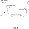
- the controller causes the weld cycle to be that of Figure 4 , in the preferred embodiment, with a weld cycle 400 comprised of a peak portion 401, a transition down portion 402, a background portion 403 and a transition up portion 404.
- the peak portion 401 and background portion 403 are the controlled voltage portion of the pulse cycle.
- the transition down portion 402 and the transition up portion 404 are the controlled current portions of the pulse cycle in the prior art, but are a targeted voltage in the preferred embodiment.
- a system for providing welding system 700 in accordance with the present disclosure includes a power source comprised of an input circuit 701, a power circuit 703 and an output circuit 705, a wire feeder 709, that are controlled by a controller 707 to produce a welding output.
- the various components may be disposed in separate or common housings, and may be in more than one housing (a portion of controller 707 can share a housing with the source, while another portion share a housing with wire feeder 709).
- Power circuit includes circuitry capable of supplying welding type power including converters, resonant power supplies, quasi-resonant power supplies, etc., and ancillary circuitry associated therewith.
- the power source is a Miller networked power source such as that described in U.S. Pat. No. 6,329,636 or U.S. Pat. No. 6,909,067 and wire feeder 709 is a Miller networked wire feeder. Other wire feeders and power supplies may be used to implement the invention. Controller 707 is part of the commercially available components in the preferred embodiments.
- system 700 be another power supply, such as a CMT, RMD®, Accupulse®, IQ pulse®, or AC MIG power supply and provide the corresponding output, or other welding output.
- CMT output is an output that may be used for CMT welding.
- AC MIG output is an output that may be used for AC MIG welding.
- CMT power source includes a power source that provides a CMT output.
- AC MIG power source is a power source that provides an AC MIG output.
- Input circuit 701 receives input power that can be 115 VAC single phase or 230/460 VAC three phase, or other utility or engine/generator power inputs. Preferably the input power is rectified and conditioned to be the intermediate power.
- Input circuit refers to circuits configured to receive an input signal and to provide an intermediate power signal,and may include things such as a rectifier, a transformer, a saturable reactor, a converter, an inverter, a filter, and/or a magnetic amplifier.
- Power circuit 703 is preferably a high frequency DC to DC converter, such as a buck, boost, half bridge etc.
- a switch 704 is used to represent the switches in the converter, and may be comprised of one or more switches such as FETs. Other topologies may be used.
- Power circuit 703 preferably includes a power transformer to isolate the intermediate input from the welding output.
- Power circuit includes circuitry capable of supplying welding type power including converters, resonant power supplies, quasi-resonant power supplies, etc.
- Power circuit 703 has a power control input 710 which provides the current command signal as an input to the converter. Then converter uses switch 704 to create the high power welding output. The output power is responsive to the power control input 710.
- Control input as used herein, is an input to a circuit, such as a power circuit, that controls the output of the circuit
- Power circuit 703 receives high voltage low current intermediate power and provides low voltage high current pulse welding output power to the output circuit 705.
- Output circuit refers to circuits configured to receive power and to provide output power, and may include filters, converters, transformers, etc.
- Power is delivered to wire feeder 709 by output circuit 705.
- output circuit 705 may be part of wire feeder 709.
- Wire feeder 709 feeds a spool of wire to the welding arc at a constant or controlled rate.
- the wire is burned off with the output current as controlled by the controller 707
- the wire feed speed is set by the controller and sent to the wire feeder on line 712.
- a feedback circuit 713 (or 711) provides a feedback signal responsive to the output voltage and responsive to the output current to controller 707.
- controller 707 uses the voltage and current feedback to control the welding pulse cycle.
- Feedback circuit is a circuit that cooperate to provide a feedback signal to a controller.
- Feedback signal includes one or more signals that provide information about one or more parameters being monitored, such as output current and output voltage.
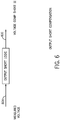
- controller 707 has a peak module 902, a transition down module 903, a background module 904, and a transition up module 901.
- Each module controls a particular portion of the pulse waveform The sequence will be explained starting with the peak module, but since this is a cyclical process, any portion could be considered as the start.
- Peak module 902 takes control and regulates a controlled voltage output during the peak portion of the waveform The constant or controlled voltage maintains a constant or controlled arc length.
- Each module is preferably implemented with software, although hardware could be used.
- One embodiment uses the same code for modules 901-904, with different target parameters for each module.
- the transition down portion begins. This is a controlled current transition which is responsive to the output voltage.
- the controller then begins the background portion of the pulse waveform.
- the background module 904 regulates the welding output in controlled voltage mode. The sequence ends with the transition up portion.
- the transition up is a controlled transition responsive to output voltage. The cycle then repeats.
- Alternatives not being part of the present invention provide that all four portions are controlled voltage portions.
- Controller 707 sequentially activates each module.
- the peak module starts the cycle by pulling desired voltages from the index table (Table 2 as described below). Each point in the index table is the desired voltage for a 50 usec time period At the end of the peak the controller activates the transition down module, then the background module, then the transition up module, and then back to the peak module, thereby commanding a welding cycle.
- One or both of the peak module and the background module are controlled voltage modules. These modules have the primary duty to maintain a generally constant output voltage and hence a generally constant arc length.
- One or both of the transition up module and transition down module is a controlled current module, modified in accordance to the present disclosure to be responsive to the feedback output voltage, as described below.
- one or both of the transition up module and transition down module is responsive to a difference between a desired transition voltage and a previous transition voltage during at least one prior welding output cycle, and/or responsive to a difference between a measured output voltage and a background voltage from at least one prior cycle divided by the difference between the background voltage from the at least one prior cycle and a peak voltage from the at least one prior cycle.
- the at least one prior cycle is a plurality of prior cycles, and more specifically 16 cycle, in various embodiments.
- the prior cycles are the immediately prior cycles in the preferred embodiment, but could be earlier cycles.
- transition modules are responsive to a conductance multiplied by a desired output voltage.
- the conductance multiplied by the commanded current should give the desired voltage.
- error corrections can be made as described below. Look up table for the desired voltages can be used, and they can be based on formula, a plurality of prior cycles, or a plurality of predetermined values. Again, error between the actual and desired voltage can be used to correct or change the command so that the desired voltage is more likely obtained. The correction can be dependent on whether or not the output is in an arc state or a short state.
- control scheme provides that the steady state portion of the peak and background are measured. One or more samples are used for this measurement. Measurements are done on the prior pulse to affect changes for the next pulse. Feedback for both the current and the voltage are measured. Alternatives provide for using more than one prior pulse, or other than the immediately prior pulse.
- the ideal model for the curves and ramps may be calculated or based off a look-up table 905 (a predefined array of waveform values). These tables generally contain the voltage and currents desired at all times in the S-shaped waveform including the desired peak and desired background, if the prior art waveform of Figure 3 is used.
- the error could also be compensated for the new Vtransition, to anticipate the error of the new command. This can be done with a derivative control or by adjusting the Measured Vactual by New Vtransition/ Previous Vtransition and computing error on the Present Vtransition.
- Another embodiment uses a look-up table with conductance.
- the conductance is the programed currents divided by the voltage for each point in the pulse waveform
- the current transition is a function of the transition voltage times the conductance from the look-up table.
- the look-up table can then be compensated based on feedback. From the voltage and current from the last transition new conductance values can be calculated and used to update the table to account for the difference between measured values and expected or desired values.
- Yet another embodiment uses actual voltages and currents, averaged from previous waveform cycles.
- an array of values is calculated again but with conductances that are calculated from actual voltages and currents averaged from previous welding cycles.
- the current values of the Transition up and Transition down values from the look-up table are modified based on the output feedback and a feed-forward model in the above alternatives.
- the initial waveforms are generated from taught values, such as that in Table 1.
- Taught values refers to values corresponding to desired output parameters of various portions or times of a weld cycle that have been previously taught to or stored in the controller. From the taught peak voltage, peak current, background voltage, background current, pulse-width and frequency, the three waveforms of Taught Current, Desired Voltage and Taught Conductance are calculated, and shown in Table 2.
- the preferred embodiment has extended the voltage compensation to be used over the entire waveform, not just during the transitions. It is based on the conductance index containing all the information needed to generate the desired waveform The index has values for every 50 usec of the pulse waveform - including all portions (see Table 2 above).
- the waveform compensation feedback is run in the control loop every 50 usec
- a 50usec control loop runs algorithms that set various parameters.
- a Short Compensation algorithm increases VoltageCompShort a small amount if there is a low minimal short response, and increases VoltageCompShort a larger amount if there is a hard short response, and if no short response then VoltageCompShort will decrement towards zero.
- the measured peak voltage and current and background voltage and current are used to recompute the conductance table.
- One embodiment provides for averaging 16 peaks and 16 backgrounds to get the average. A new peak conductance is calculated using these values, and a new background conductance is calculated based on these. These values are then used to scale a new conductance waveform
- the entire waveform of conductance, voltage and /or current is calculated in the background (not an interrupt), in one embodiment. However it could be calculated in the 50 us interrupt as well,or only the conductance needed for that 50 us interval could be calculated.
- the VoltageCompShort could have individual 50 us values, or a single value used to compensate the entire waveform. Resistance could be used instead of conductance. Verror could be used instead of the VerrorSum, but would require some scaling.
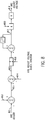
- I current command 800 is the NewDesiredVoltage 802 divided by the Conductance [I] 801.
- NewDesiredVoltage 802 is the sum of four variables: WaveformVoltage[i] 803, VerrorSum/scaling 809, VoltagecompShort[i] 810 and ArcAdjustVoltage 818.
- WaveformVoltage[i] 803 is taken from the index table, VerrorSum 807 / scaling is 809 is VerrorSum plus Verror 806.
- Verror 806 is last DesiredVoltage 805 minus MeasuredVoltage 804.
- VoltagecompShort[i] 810 is a small additional compensation used only during the time when a short is detected from MeasuredVoltage 804. VoltagecompShort[i] 810 is increased a small amount if there is a minimal short and increased a larger amount if there is a hard short. If there is no short, VoltagecompShort[i] 810 is decreased a little till it is zero.
- ArcAdjustVoltage 818 is a voltage trim that the welding operator can vary to suit their style of welding. It is common in the industry to have a voltage trim on pulse welding power supplies where the waveform is otherwise dictated by the preprogramed tables.
- ArcAdjustVoltage 818 is calculated from gPercentArcAdjust 817 multiplied by DesiredVoltageWaveform[i] 803 take from the table.
- gPercentArcAdjust 817 is the sum of the last gPercentArcAdjust 817, and ArcAdjustVoltageError 815 divided by AvgWavefonnAdaptiveVoltage 816.
- ArcAdjustVoltageError 815 the DesiredArcAdjustVoltage 813 minus the ActualWaveformVoltage 814.
- DesiredArcAdjustVoltage 813 is the sum of the AvgWaveformAdaptiveVoltage 812 plus the user input ArcAdjust 811 less 50.
- the conductance table can be changed based on the average values of peak and background voltage and current, such as a 16 pulse average.
- controller 707 controls system 700 to provide a controlled voltage during at least one of the peak portion and the background portion, and preferably during both, and, during one or both of the transition portions the switching of switch 704 is controlled by a voltage ramping algorithm that tracks to a target voltage waveform shape.
- the voltage waveform shape can be stored in look up table 905, or in other memory.
- the commands that controller 707 provides to obtain the desired voltage waveform may be adjusted based on prior history to reduce the difference between the desired value and actual value, as described in various ways above. This allows a controlled current power supply to provide a controlled voltage process.
- transitions are controlled to follow a voltage waveform and/or a controlled voltage portion and/or controlled current using a voltage feedback
- the peak and background portions can be either cc, cv, controlled current or voltage, a combination thereof, or use other control loops such as heat input, average voltage or current, power, etc.
- control loops described above can be used with any of the waveforms described herein, and/or can be use on one portion of the welding cycle, a plurality of portions of the welding cycle, or all of the welding cycle.
Landscapes
- Engineering & Computer Science (AREA)
- Physics & Mathematics (AREA)
- Plasma & Fusion (AREA)
- Mechanical Engineering (AREA)
- Theoretical Computer Science (AREA)
- Arc Welding Control (AREA)
- Generation Of Surge Voltage And Current (AREA)
Claims (14)
- Système de type soudage destiné à mettre en œuvre une pluralité de cycles de soudage, chaque cycle comportant une partie de crête (401), une partie de transition descendante (402), une partie de fond (403), et une partie de transition ascendante (404), comprenant :- un circuit d'entrée (701) disposé pour recevoir une puissance d'entrée et pour fournir une puissance intermédiaire ;- un circuit d'alimentation (703), ayant une entrée de contrôle d'alimentation (710) et au moins un commutateur (704) sensible à l'entrée de contrôle d'alimentation (710), et le circuit d'alimentation (703) étant disposé pour recevoir la puissance intermédiaire et fournir une puissance de sortie de type soudage à un circuit de sortie (705), la puissance de sortie ayant une tension de sortie et un courant de sortie ;- un circuit de rétroaction (713), ayant un signal de rétroaction sensible à au moins une de la tension de sortie et sensible au courant de sortie ; et- un contrôleur (707), qui reçoit le signal de rétroaction, et ayant un module de crête (902), un module de transition descendante (903), un module de fond (904), et un module de transition ascendante (901), le contrôleur (707) activant séquentiellement le module de crête (902), puis le module de transition descendante (903), puis le module de fond (904), puis le module de transition ascendante (901), et ensuite de nouveau le module de crête (902), commandant ainsi un cycle de soudage ;dans lequel au moins un du module de crête (902) et du module de fond (904) est un module de tension contrôlée, et au moins un du module de transition ascendante (901) et du module de transition descendante (903) est un module de courant contrôlé ; et
dans lequel au moins un du module de transition ascendante (901) et du module de transition descendante (903) a une sortie de commande de courant de transition qui est sensible à la tension de sortie,
caractérisé en ce que
la sortie de commande de courant de transition pour l'au moins un du module de transition ascendante (901) et du module de transition descendante (903) est sensible à une différence entre une tension de transition souhaitée et une tension de transition précédente pendant au moins un cycle de sortie de soudage antérieur. - Système de la revendication 1,
dans lequel le module de transition ascendante (901) et le module de transition descendante (903) sont tous deux des modules de courant contrôlé, et dans lequel, en outre, le module de transition ascendante (901) et le module de transition descendante (903) ont tous deux une sortie de commande de courant de transition qui est sensible à la tension de sortie. - Système de la revendication 1 ou 2,
dans lequel la sortie de commande de courant de transition pour l'au moins un du module de transition ascendante (901) et du module de transition descendante (903) est en outre sensible à une différence entre une tension de sortie mesurée et une tension de fond issue d'au moins un cycle antérieur divisée par la différence entre la tension de fond issue de l'au moins un cycle antérieur et une tension de crête issue de l'au moins un cycle antérieur. - Système de la revendication 3,
dans lequel l'au moins un cycle antérieur est une pluralité de cycles antérieurs. - Système d'une des revendications précédentes,
dans lequel la sortie de commande de courant de transition pour l'au moins un du module de transition ascendante (901) et du module de transition descendante (903) est fournie pour une transition et est sensible à une conductance multipliée par une tension de sortie souhaitée. - Système de la revendication 5,
dans lequel la conductance varie sur la transition sur la base d'au moins un élément parmi une formule, une pluralité de cycles antérieurs, et une pluralité de valeurs prédéterminées. - Système de la revendication 6,
dans lequel la tension de sortie souhaitée est sensible à une pluralité de valeurs apprises et une différence entre une tension de sortie souhaitée antérieure et une tension réelle antérieure pour au moins un cycle antérieur. - Système de la revendication 7,
dans lequel la tension de sortie souhaitée est en outre sensible au fait que la sortie est ou n'est pas un état d'arc ou un état de court-circuit. - Procédé de fourniture d'une puissance de type soudage,
dans lequel la puissance de type soudage est fournie sous la forme d'une pluralité de cycles de soudage, chaque cycle comportant une partie de crête (401), une partie de transition descendante (402), une partie de fond (403), et une partie de transition ascendante (404), comprenant :- la réception d'une puissance d'entrée et la fourniture d'une puissance intermédiaire ;- la réception de la puissance intermédiaire et la commutation de la puissance intermédiaire pour fournir une puissance de sortie de type soudage, la puissance de sortie ayant une tension de sortie et un courant de sortie ;- la fourniture d'un signal de rétroaction sensible à la tension de sortie et sensible au courant de sortie ; et- le contrôle de la commutation en réponse au signal de rétroaction pour fournir la partie de crête (401), la partie de transition descendante (402), la partie de fond (403), et la partie de transition ascendante (404), et mettre ainsi en œuvre un cycle de soudage ;dans lequel la commutation est contrôlée pour fournir une tension contrôlée pendant au moins une de la partie de crête (401) et de la partie de fond (403) ; et
dans lequel la commutation est contrôlée pour fournir un courant contrôlé pendant au moins une de la partie de transition ascendante (404) et de la partie de transition descendante (402), et dans lequel la commutation est en outre contrôlée pendant au moins une de la partie de transition ascendante (404) et de la partie de transition descendante (402) en réponse à la tension de sortie,
caractérisé en ce que
une commande de courant de transition pendant la partie de transition ascendante (404) et la partie de transition descendante (402) est sensible à une différence entre une tension de transition souhaitée et une tension de transition précédente sur au moins un cycle de sortie de soudage antérieur. - Procédé de la revendication 9,
dans lequel, à la fois pendant la partie de transition ascendante (404) et la partie de transition descendante (402), la commutation est contrôlée pour fournir un courant contrôlé, et dans lequel la commutation est en outre contrôlée à la fois pendant la partie de transition ascendante (404) et la partie de transition descendante (402) en réponse à la tension de sortie. - Procédé de la revendication 9 ou 10,
dans lequel la commande de courant de transition est en outre sensible à une différence entre une tension de sortie mesurée et une tension de fond issue d'au moins un cycle antérieur divisée par la différence entre la tension de fond issue de l'au moins un cycle antérieur et une tension de crête issue de l'au moins un cycle antérieur. - Procédé d'une des revendications 9 à 11,
dans lequel une commande de courant de transition pendant la partie de transition ascendante (404) et la partie de transition descendante (402) est sensible à une conductance multipliée par une tension de sortie souhaitée et/ou une fonction d'un rapport de la différence entre un courant de crête et un courant de fond. - Procédé de la revendication 12,
dans lequel la conductance varie sur la transition sur la base d'au moins un élément parmi une formule, une pluralité de cycles antérieurs, et une pluralité de valeurs prédéterminées. - Procédé de la revendication 13,
dans lequel la tension de sortie souhaitée est sensible à une pluralité de valeurs apprises et une différence entre une tension de sortie souhaitée antérieure et une tension réelle antérieure pour au moins un cycle antérieur, et dans lequel la tension de sortie souhaitée est en outre sensible au fait que la sortie est ou n'est pas un état d'arc ou un état de court-circuit.
Applications Claiming Priority (3)
| Application Number | Priority Date | Filing Date | Title |
|---|---|---|---|
| US201562206795P | 2015-08-18 | 2015-08-18 | |
| US15/237,308 US10857610B2 (en) | 2015-08-18 | 2016-08-15 | Method and apparatus for pulse welding |
| PCT/US2016/047155 WO2017031108A1 (fr) | 2015-08-18 | 2016-08-16 | Procédé et appareil de soudage par impulsions |
Publications (2)
| Publication Number | Publication Date |
|---|---|
| EP3337633A1 EP3337633A1 (fr) | 2018-06-27 |
| EP3337633B1 true EP3337633B1 (fr) | 2020-08-12 |
Family
ID=57137227
Family Applications (1)
| Application Number | Title | Priority Date | Filing Date |
|---|---|---|---|
| EP16781883.0A Active EP3337633B1 (fr) | 2015-08-18 | 2016-08-16 | Methode et appareil pour soudage par impulsion |
Country Status (6)
| Country | Link |
|---|---|
| US (2) | US10857610B2 (fr) |
| EP (1) | EP3337633B1 (fr) |
| CN (1) | CN108136530A (fr) |
| CA (1) | CA2994979C (fr) |
| MX (1) | MX378684B (fr) |
| WO (1) | WO2017031108A1 (fr) |
Families Citing this family (7)
| Publication number | Priority date | Publication date | Assignee | Title |
|---|---|---|---|---|
| US10857610B2 (en) | 2015-08-18 | 2020-12-08 | Illinois Tool Works Inc. | Method and apparatus for pulse welding |
| IT201700106957A1 (it) * | 2017-09-25 | 2019-03-25 | Bcs Spa | Motosaldatrice e metodo di controllo della stessa |
| JP6599956B2 (ja) * | 2017-10-23 | 2019-10-30 | ファナック株式会社 | 工作機械の加工条件選定装置 |
| US11958142B2 (en) * | 2018-10-19 | 2024-04-16 | Illinois Tool Works Inc. | Systems and methods to control pulse welding |
| US12128508B2 (en) * | 2018-10-22 | 2024-10-29 | Illinois Tool Works Inc. | Systems and methods for controlling arc initiation and termination in a welding process |
| JP7251988B2 (ja) * | 2019-01-22 | 2023-04-04 | 株式会社神戸製鋼所 | パルスアーク溶接の倣い制御方法、制御装置、溶接システム、溶接プログラム及び溶接電源 |
| CN121568805A (zh) * | 2023-07-24 | 2026-02-24 | 依赛彼集团公司 | 受控短弧气体金属弧焊中的波形调节 |
Family Cites Families (8)
| Publication number | Priority date | Publication date | Assignee | Title |
|---|---|---|---|---|
| US5001326A (en) | 1986-12-11 | 1991-03-19 | The Lincoln Electric Company | Apparatus and method of controlling a welding cycle |
| US5742029A (en) | 1996-07-15 | 1998-04-21 | The Lincoln Electric Company | Method of welding wallpaper alloy an arc welder modified to practice same |
| US6329636B1 (en) * | 2000-03-31 | 2001-12-11 | Illinois Tool Works Inc. | Method and apparatus for receiving a universal input voltage in a welding plasma or heating power source |
| US6909067B2 (en) | 2002-10-09 | 2005-06-21 | Illinois Tool Works Inc. | Method and apparatus for welding with CV control |
| US8704131B2 (en) * | 2006-03-31 | 2014-04-22 | Illinois Tool Works Inc. | Method and apparatus for pulse welding |
| WO2008137371A2 (fr) | 2007-04-30 | 2008-11-13 | Illinois Tool Works Inc. | Système de soudage et procédé à forme d'onde améliorée |
| US10315268B2 (en) * | 2012-11-07 | 2019-06-11 | Lincoln Global, Inc. | Method and system to control heat input in a welding operation |
| US10857610B2 (en) | 2015-08-18 | 2020-12-08 | Illinois Tool Works Inc. | Method and apparatus for pulse welding |
-
2016
- 2016-08-15 US US15/237,308 patent/US10857610B2/en active Active
- 2016-08-16 EP EP16781883.0A patent/EP3337633B1/fr active Active
- 2016-08-16 MX MX2018002035A patent/MX378684B/es unknown
- 2016-08-16 CA CA2994979A patent/CA2994979C/fr active Active
- 2016-08-16 CN CN201680059327.3A patent/CN108136530A/zh active Pending
- 2016-08-16 WO PCT/US2016/047155 patent/WO2017031108A1/fr not_active Ceased
-
2020
- 2020-12-08 US US17/115,507 patent/US12162099B2/en active Active
Non-Patent Citations (1)
| Title |
|---|
| None * |
Also Published As
| Publication number | Publication date |
|---|---|
| US10857610B2 (en) | 2020-12-08 |
| CN108136530A (zh) | 2018-06-08 |
| CA2994979C (fr) | 2020-11-24 |
| MX378684B (es) | 2025-03-11 |
| WO2017031108A1 (fr) | 2017-02-23 |
| EP3337633A1 (fr) | 2018-06-27 |
| US20210086281A1 (en) | 2021-03-25 |
| US12162099B2 (en) | 2024-12-10 |
| CA2994979A1 (fr) | 2017-02-23 |
| MX2018002035A (es) | 2018-04-13 |
| US20170050255A1 (en) | 2017-02-23 |
Similar Documents
| Publication | Publication Date | Title |
|---|---|---|
| US12162099B2 (en) | Method and apparatus for pulse welding | |
| EP1407849B1 (fr) | Procédé et dispositif pour soudage avec contrôle de la tension constante | |
| US8704131B2 (en) | Method and apparatus for pulse welding | |
| JP2002361418A (ja) | 電気アーク溶接機を制御するための装置および方法 | |
| US11958142B2 (en) | Systems and methods to control pulse welding | |
| CN111069733B (zh) | 控制脉冲焊接的系统和方法 | |
| US12115604B2 (en) | Systems and methods for voltage control of a short circuit during a pulse welding process | |
| EP3345709A1 (fr) | Alimentation électrique et procédé dual de soudage | |
| US12128508B2 (en) | Systems and methods for controlling arc initiation and termination in a welding process | |
| CN108430685B (zh) | 恒定电流控制系统和方法 |
Legal Events
| Date | Code | Title | Description |
|---|---|---|---|
| STAA | Information on the status of an ep patent application or granted ep patent |
Free format text: STATUS: UNKNOWN |
|
| STAA | Information on the status of an ep patent application or granted ep patent |
Free format text: STATUS: THE INTERNATIONAL PUBLICATION HAS BEEN MADE |
|
| PUAI | Public reference made under article 153(3) epc to a published international application that has entered the european phase |
Free format text: ORIGINAL CODE: 0009012 |
|
| STAA | Information on the status of an ep patent application or granted ep patent |
Free format text: STATUS: REQUEST FOR EXAMINATION WAS MADE |
|
| 17P | Request for examination filed |
Effective date: 20180214 |
|
| AK | Designated contracting states |
Kind code of ref document: A1 Designated state(s): AL AT BE BG CH CY CZ DE DK EE ES FI FR GB GR HR HU IE IS IT LI LT LU LV MC MK MT NL NO PL PT RO RS SE SI SK SM TR |
|
| AX | Request for extension of the european patent |
Extension state: BA ME |
|
| DAV | Request for validation of the european patent (deleted) | ||
| DAX | Request for extension of the european patent (deleted) | ||
| GRAP | Despatch of communication of intention to grant a patent |
Free format text: ORIGINAL CODE: EPIDOSNIGR1 |
|
| STAA | Information on the status of an ep patent application or granted ep patent |
Free format text: STATUS: GRANT OF PATENT IS INTENDED |
|
| INTG | Intention to grant announced |
Effective date: 20200311 |
|
| GRAS | Grant fee paid |
Free format text: ORIGINAL CODE: EPIDOSNIGR3 |
|
| GRAA | (expected) grant |
Free format text: ORIGINAL CODE: 0009210 |
|
| STAA | Information on the status of an ep patent application or granted ep patent |
Free format text: STATUS: THE PATENT HAS BEEN GRANTED |
|
| AK | Designated contracting states |
Kind code of ref document: B1 Designated state(s): AL AT BE BG CH CY CZ DE DK EE ES FI FR GB GR HR HU IE IS IT LI LT LU LV MC MK MT NL NO PL PT RO RS SE SI SK SM TR |
|
| REG | Reference to a national code |
Ref country code: CH Ref legal event code: EP |
|
| REG | Reference to a national code |
Ref country code: IE Ref legal event code: FG4D |
|
| REG | Reference to a national code |
Ref country code: DE Ref legal event code: R096 Ref document number: 602016041921 Country of ref document: DE |
|
| REG | Reference to a national code |
Ref country code: AT Ref legal event code: REF Ref document number: 1301068 Country of ref document: AT Kind code of ref document: T Effective date: 20200915 |
|
| PGFP | Annual fee paid to national office [announced via postgrant information from national office to epo] |
Ref country code: FR Payment date: 20200925 Year of fee payment: 5 Ref country code: GB Payment date: 20200928 Year of fee payment: 5 |
|
| REG | Reference to a national code |
Ref country code: LT Ref legal event code: MG4D |
|
| REG | Reference to a national code |
Ref country code: NL Ref legal event code: MP Effective date: 20200812 |
|
| PG25 | Lapsed in a contracting state [announced via postgrant information from national office to epo] |
Ref country code: FI Free format text: LAPSE BECAUSE OF FAILURE TO SUBMIT A TRANSLATION OF THE DESCRIPTION OR TO PAY THE FEE WITHIN THE PRESCRIBED TIME-LIMIT Effective date: 20200812 Ref country code: NO Free format text: LAPSE BECAUSE OF FAILURE TO SUBMIT A TRANSLATION OF THE DESCRIPTION OR TO PAY THE FEE WITHIN THE PRESCRIBED TIME-LIMIT Effective date: 20201112 Ref country code: GR Free format text: LAPSE BECAUSE OF FAILURE TO SUBMIT A TRANSLATION OF THE DESCRIPTION OR TO PAY THE FEE WITHIN THE PRESCRIBED TIME-LIMIT Effective date: 20201113 Ref country code: BG Free format text: LAPSE BECAUSE OF FAILURE TO SUBMIT A TRANSLATION OF THE DESCRIPTION OR TO PAY THE FEE WITHIN THE PRESCRIBED TIME-LIMIT Effective date: 20201112 Ref country code: SE Free format text: LAPSE BECAUSE OF FAILURE TO SUBMIT A TRANSLATION OF THE DESCRIPTION OR TO PAY THE FEE WITHIN THE PRESCRIBED TIME-LIMIT Effective date: 20200812 Ref country code: LT Free format text: LAPSE BECAUSE OF FAILURE TO SUBMIT A TRANSLATION OF THE DESCRIPTION OR TO PAY THE FEE WITHIN THE PRESCRIBED TIME-LIMIT Effective date: 20200812 Ref country code: HR Free format text: LAPSE BECAUSE OF FAILURE TO SUBMIT A TRANSLATION OF THE DESCRIPTION OR TO PAY THE FEE WITHIN THE PRESCRIBED TIME-LIMIT Effective date: 20200812 |
|
| REG | Reference to a national code |
Ref country code: AT Ref legal event code: MK05 Ref document number: 1301068 Country of ref document: AT Kind code of ref document: T Effective date: 20200812 |
|
| PG25 | Lapsed in a contracting state [announced via postgrant information from national office to epo] |
Ref country code: LV Free format text: LAPSE BECAUSE OF FAILURE TO SUBMIT A TRANSLATION OF THE DESCRIPTION OR TO PAY THE FEE WITHIN THE PRESCRIBED TIME-LIMIT Effective date: 20200812 Ref country code: NL Free format text: LAPSE BECAUSE OF FAILURE TO SUBMIT A TRANSLATION OF THE DESCRIPTION OR TO PAY THE FEE WITHIN THE PRESCRIBED TIME-LIMIT Effective date: 20200812 Ref country code: PL Free format text: LAPSE BECAUSE OF FAILURE TO SUBMIT A TRANSLATION OF THE DESCRIPTION OR TO PAY THE FEE WITHIN THE PRESCRIBED TIME-LIMIT Effective date: 20200812 Ref country code: RS Free format text: LAPSE BECAUSE OF FAILURE TO SUBMIT A TRANSLATION OF THE DESCRIPTION OR TO PAY THE FEE WITHIN THE PRESCRIBED TIME-LIMIT Effective date: 20200812 Ref country code: IS Free format text: LAPSE BECAUSE OF FAILURE TO SUBMIT A TRANSLATION OF THE DESCRIPTION OR TO PAY THE FEE WITHIN THE PRESCRIBED TIME-LIMIT Effective date: 20201212 |
|
| REG | Reference to a national code |
Ref country code: CH Ref legal event code: PL |
|
| PG25 | Lapsed in a contracting state [announced via postgrant information from national office to epo] |
Ref country code: EE Free format text: LAPSE BECAUSE OF FAILURE TO SUBMIT A TRANSLATION OF THE DESCRIPTION OR TO PAY THE FEE WITHIN THE PRESCRIBED TIME-LIMIT Effective date: 20200812 Ref country code: SM Free format text: LAPSE BECAUSE OF FAILURE TO SUBMIT A TRANSLATION OF THE DESCRIPTION OR TO PAY THE FEE WITHIN THE PRESCRIBED TIME-LIMIT Effective date: 20200812 Ref country code: RO Free format text: LAPSE BECAUSE OF FAILURE TO SUBMIT A TRANSLATION OF THE DESCRIPTION OR TO PAY THE FEE WITHIN THE PRESCRIBED TIME-LIMIT Effective date: 20200812 Ref country code: DK Free format text: LAPSE BECAUSE OF FAILURE TO SUBMIT A TRANSLATION OF THE DESCRIPTION OR TO PAY THE FEE WITHIN THE PRESCRIBED TIME-LIMIT Effective date: 20200812 Ref country code: CZ Free format text: LAPSE BECAUSE OF FAILURE TO SUBMIT A TRANSLATION OF THE DESCRIPTION OR TO PAY THE FEE WITHIN THE PRESCRIBED TIME-LIMIT Effective date: 20200812 Ref country code: CH Free format text: LAPSE BECAUSE OF NON-PAYMENT OF DUE FEES Effective date: 20200831 Ref country code: LI Free format text: LAPSE BECAUSE OF NON-PAYMENT OF DUE FEES Effective date: 20200831 Ref country code: LU Free format text: LAPSE BECAUSE OF NON-PAYMENT OF DUE FEES Effective date: 20200816 |
|
| REG | Reference to a national code |
Ref country code: DE Ref legal event code: R097 Ref document number: 602016041921 Country of ref document: DE |
|
| REG | Reference to a national code |
Ref country code: BE Ref legal event code: MM Effective date: 20200831 |
|
| PG25 | Lapsed in a contracting state [announced via postgrant information from national office to epo] |
Ref country code: MC Free format text: LAPSE BECAUSE OF FAILURE TO SUBMIT A TRANSLATION OF THE DESCRIPTION OR TO PAY THE FEE WITHIN THE PRESCRIBED TIME-LIMIT Effective date: 20200812 Ref country code: AL Free format text: LAPSE BECAUSE OF FAILURE TO SUBMIT A TRANSLATION OF THE DESCRIPTION OR TO PAY THE FEE WITHIN THE PRESCRIBED TIME-LIMIT Effective date: 20200812 Ref country code: AT Free format text: LAPSE BECAUSE OF FAILURE TO SUBMIT A TRANSLATION OF THE DESCRIPTION OR TO PAY THE FEE WITHIN THE PRESCRIBED TIME-LIMIT Effective date: 20200812 Ref country code: ES Free format text: LAPSE BECAUSE OF FAILURE TO SUBMIT A TRANSLATION OF THE DESCRIPTION OR TO PAY THE FEE WITHIN THE PRESCRIBED TIME-LIMIT Effective date: 20200812 |
|
| PLBE | No opposition filed within time limit |
Free format text: ORIGINAL CODE: 0009261 |
|
| STAA | Information on the status of an ep patent application or granted ep patent |
Free format text: STATUS: NO OPPOSITION FILED WITHIN TIME LIMIT |
|
| PG25 | Lapsed in a contracting state [announced via postgrant information from national office to epo] |
Ref country code: SK Free format text: LAPSE BECAUSE OF FAILURE TO SUBMIT A TRANSLATION OF THE DESCRIPTION OR TO PAY THE FEE WITHIN THE PRESCRIBED TIME-LIMIT Effective date: 20200812 |
|
| 26N | No opposition filed |
Effective date: 20210514 |
|
| PG25 | Lapsed in a contracting state [announced via postgrant information from national office to epo] |
Ref country code: IT Free format text: LAPSE BECAUSE OF FAILURE TO SUBMIT A TRANSLATION OF THE DESCRIPTION OR TO PAY THE FEE WITHIN THE PRESCRIBED TIME-LIMIT Effective date: 20200812 |
|
| PG25 | Lapsed in a contracting state [announced via postgrant information from national office to epo] |
Ref country code: IE Free format text: LAPSE BECAUSE OF NON-PAYMENT OF DUE FEES Effective date: 20200816 Ref country code: SI Free format text: LAPSE BECAUSE OF FAILURE TO SUBMIT A TRANSLATION OF THE DESCRIPTION OR TO PAY THE FEE WITHIN THE PRESCRIBED TIME-LIMIT Effective date: 20200812 Ref country code: BE Free format text: LAPSE BECAUSE OF NON-PAYMENT OF DUE FEES Effective date: 20200831 |
|
| GBPC | Gb: european patent ceased through non-payment of renewal fee |
Effective date: 20210816 |
|
| PG25 | Lapsed in a contracting state [announced via postgrant information from national office to epo] |
Ref country code: TR Free format text: LAPSE BECAUSE OF FAILURE TO SUBMIT A TRANSLATION OF THE DESCRIPTION OR TO PAY THE FEE WITHIN THE PRESCRIBED TIME-LIMIT Effective date: 20200812 Ref country code: MT Free format text: LAPSE BECAUSE OF FAILURE TO SUBMIT A TRANSLATION OF THE DESCRIPTION OR TO PAY THE FEE WITHIN THE PRESCRIBED TIME-LIMIT Effective date: 20200812 Ref country code: CY Free format text: LAPSE BECAUSE OF FAILURE TO SUBMIT A TRANSLATION OF THE DESCRIPTION OR TO PAY THE FEE WITHIN THE PRESCRIBED TIME-LIMIT Effective date: 20200812 |
|
| PG25 | Lapsed in a contracting state [announced via postgrant information from national office to epo] |
Ref country code: MK Free format text: LAPSE BECAUSE OF FAILURE TO SUBMIT A TRANSLATION OF THE DESCRIPTION OR TO PAY THE FEE WITHIN THE PRESCRIBED TIME-LIMIT Effective date: 20200812 |
|
| PG25 | Lapsed in a contracting state [announced via postgrant information from national office to epo] |
Ref country code: PT Free format text: LAPSE BECAUSE OF FAILURE TO SUBMIT A TRANSLATION OF THE DESCRIPTION OR TO PAY THE FEE WITHIN THE PRESCRIBED TIME-LIMIT Effective date: 20200812 Ref country code: GB Free format text: LAPSE BECAUSE OF NON-PAYMENT OF DUE FEES Effective date: 20210816 Ref country code: FR Free format text: LAPSE BECAUSE OF NON-PAYMENT OF DUE FEES Effective date: 20210831 |
|
| P01 | Opt-out of the competence of the unified patent court (upc) registered |
Effective date: 20230606 |
|
| PGFP | Annual fee paid to national office [announced via postgrant information from national office to epo] |
Ref country code: DE Payment date: 20250827 Year of fee payment: 10 |