EP3337680B1 - Pneumatique - Google Patents
Pneumatique Download PDFInfo
- Publication number
- EP3337680B1 EP3337680B1 EP16715554.8A EP16715554A EP3337680B1 EP 3337680 B1 EP3337680 B1 EP 3337680B1 EP 16715554 A EP16715554 A EP 16715554A EP 3337680 B1 EP3337680 B1 EP 3337680B1
- Authority
- EP
- European Patent Office
- Prior art keywords
- pneumatic tyre
- absorber
- vehicle pneumatic
- adhesive
- bonding agent
- Prior art date
- Legal status (The legal status is an assumption and is not a legal conclusion. Google has not performed a legal analysis and makes no representation as to the accuracy of the status listed.)
- Active
Links
Images


Classifications
-
- B—PERFORMING OPERATIONS; TRANSPORTING
- B60—VEHICLES IN GENERAL
- B60C—VEHICLE TYRES; TYRE INFLATION; TYRE CHANGING; CONNECTING VALVES TO INFLATABLE ELASTIC BODIES IN GENERAL; DEVICES OR ARRANGEMENTS RELATED TO TYRES
- B60C19/00—Tyre parts or constructions not otherwise provided for
- B60C19/002—Noise damping elements provided in the tyre structure or attached thereto, e.g. in the tyre interior
-
- B—PERFORMING OPERATIONS; TRANSPORTING
- B29—WORKING OF PLASTICS; WORKING OF SUBSTANCES IN A PLASTIC STATE IN GENERAL
- B29D—PRODUCING PARTICULAR ARTICLES FROM PLASTICS OR FROM SUBSTANCES IN A PLASTIC STATE
- B29D30/00—Producing pneumatic or solid tyres or parts thereof
- B29D30/0061—Accessories, details or auxiliary operations not otherwise provided for
-
- B—PERFORMING OPERATIONS; TRANSPORTING
- B60—VEHICLES IN GENERAL
- B60C—VEHICLE TYRES; TYRE INFLATION; TYRE CHANGING; CONNECTING VALVES TO INFLATABLE ELASTIC BODIES IN GENERAL; DEVICES OR ARRANGEMENTS RELATED TO TYRES
- B60C17/00—Tyres characterised by means enabling restricted operation in damaged or deflated condition; Accessories therefor
- B60C17/0009—Tyres characterised by means enabling restricted operation in damaged or deflated condition; Accessories therefor comprising sidewall rubber inserts, e.g. crescent shaped inserts
Definitions
- the invention relates to a pneumatic vehicle tire according to the preamble of claim 1.
- a pneumatic vehicle tire of the type in question can be used for two-wheeled vehicles, as well as for passenger cars, agricultural vehicles and / or trucks, whose vehicle wheels are equipped with pneumatic vehicle tires, the pneumatic vehicle tires having a structured running surface, the profile of which can be matched to that expected Substrates and weather conditions is adjusted.
- the tread of the pneumatic vehicle tire is in a conventional manner on both sides in side walls, whose end is formed in each case by a tire bead.
- the tire bead serves for airtight fixing of the part of the pneumatic vehicle tire composed of different rubber compounds with a rim of the vehicle wheel to be equipped with the pneumatic vehicle tire.
- the rim has, in a likewise known manner corresponding to the tire bead, a rim edge against which the tire bead seals when the air cavity enclosed by the tubeless pneumatic vehicle tire and the rim is filled with compressed air.
- Modern pneumatic vehicle tires must nowadays not only optimally transfer the kinetic energy generated by the motor vehicle under changing environmental conditions to the ground, but also increasingly meet upscale comfort requirements.
- the rolling noise of the pneumatic vehicle tire plays a significant role, which is caused by the vibration of the air when it is compressed when pressing the pneumatic vehicle tire against the road surface. The rolling noise generated in this way is transmitted from the pneumatic vehicle tire to the wheel hub, so that it finally passes through the steering and the suspension in the passenger compartment.
- an acoustic load due to the rolling noise generated during driving is not only distracting within, but also outside of the motor vehicle, which is becoming increasingly important in cities, for example.
- the rolling noise can be significantly reduced by an already known and used in some vehicles in use technology.
- a sound-absorbing agent arranged in the vehicle pneumatic tire and often designed as a foam body absorber is used, which is cohesively, so for example with an adhesive, attached to the inside of the tread of the vehicle pneumatic tire.
- the absorber is attached to the rim of the vehicle wheel.
- the structure of this absorber which is usually made of polyurethane, is retained even under extreme temperature fluctuations.
- Polyurethanes are plastics or synthetic resins resulting from the polyaddition reaction of dialcohols or polyols with polyisocyanates.
- its speed and the road surface can be achieved by the aforementioned measures reductions of vehicle noise in the interior of the motor vehicle by up to 9 dB (A), with the introduction of the absorber in the pneumatic vehicle tires neither the driving characteristics nor the mileage, the load capacity or the achievable with the pneumatic vehicle tire speed is limited.
- Such a pneumatic vehicle tire of a vehicle wheel is an example of the DE 10 2007 028 932 A1 out.
- the document describes that the absorber embodied as a foam body is adhesively secured to the inner surface of the pneumatic vehicle tire within the vehicle pneumatic tire with a pre-applied, self-sealing sealant.
- a full-surface bonded sealant here is a polyurethane gel is used.
- a suitable for a vehicle wheel pneumatic vehicle tire and a method for producing such a pneumatic vehicle tire in which also designed as a foam body absorber before application to the inner surface of the pneumatic vehicle tire in a mold suitable for this purpose produced by a foaming and then on the interior of the vehicle pneumatic tire facing side is equipped with an additional sound-absorbing structure.
- the structure applied to the foam layer may in this case have a line shape or a wave shape, each of which is suitable for creating an enlarged surface which additionally has a sound-absorbing effect.
- DE 10 2011 053 686 A1 relates to a pneumatic vehicle tire in which either the entire inner surface of the pneumatic vehicle tire with a primer (adhesive) is provided or wetted only described in the document bases of arranged on the surface of an absorber springs with the primer, then the existing mass-forming layer with the Side of the base surfaces to the inner surface of the pneumatic vehicle tire to fix.
- a primer adheresive
- the invention has for its object to provide a vehicle pneumatic tire with an absorber suitable for sound absorption, in which the bonding between the absorber and pneumatic vehicle tires optimized and possible weight-saving and the manufacturing technology is easy to implement.
- a pneumatic vehicle tire the profiled tread merges into side walls on both sides, the end of which is airtight inserted into a rim of a vehicle wheel, wherein an absorber is integrated into the pneumatic vehicle tire for sound absorption, according to the invention further developed such that the cohesive connection an adhesive not distributed over the entire surface between the absorber and the inner surface of the pneumatic vehicle tire, which has an uneven, changing distribution along the circumference of the inner surface of the pneumatic vehicle tire.
- the inventive solution to provide a non-adhesive bonding between the absorber and the inner surface of the pneumatic vehicle tire several advantages are achieved.
- the saving of costly adhesive is an economic advantage that also leads to the reduction of the total weight of the pneumatic vehicle tire and thus equipped with the pneumatic vehicle tire vehicle wheel, which ultimately also has a positive effect on the fuel consumption of the motor vehicle.
- the adhesive has a non-uniform, varying distribution along the circumference of the inner surface of the pneumatic vehicle tire.
- the adhesive In this manner of applying the adhesive, no particular pattern or order of application of the adhesive to the inner surface of the pneumatic vehicle tire and / or to the adhesive surface of the absorber is provided.
- the adhesive can thus be applied randomly or, which corresponds to a preferred embodiment, a defined order of application of the adhesive is provided, however, the image of the adhesive application changes along the inner surface of the pneumatic vehicle tire or along the surface of the absorber.
- the adhesive may consist of a striped pattern, have a wavy line shape or form a dot matrix.
- the following examples of application of the adhesive refer to either the circumferential direction of the pneumatic vehicle tire or the direction transverse to the periphery of the pneumatic vehicle tire.
- the wavy shape of the adhesive guide can extend over the entire width of the absorber, ie transversely to the circumferential direction of the pneumatic vehicle tire, or at least over a substantial part of the width of the absorber. Considering, for example, the wavy shape, this may, viewed in the circumferential direction of the pneumatic vehicle tire, consist of a uniform, so approximately sinusoidal wave of the adhesive guide. Another variant of this wavy shape is the fact that the individual alternating wave peaks and troughs of the adhesive guide have increasing or decreasing distances from each other.
- the point matrix is to be understood in the sense according to the invention that the adhesive is distributed selectively over the inner surface of the vehicle pneumatic tire or over the surface of the absorber. More simply, the adhesive is spotted on at least one of the contact surfaces.
- the stripe pattern there are numerous, different variants of the application of the adhesive to the inner surface of the pneumatic vehicle tire or to the corresponding adhesive surface of the absorber.
- a stripe pattern can be understood here, the strips of which each have identical or unequal distances or identical or unequal dimensions.
- the fringe pattern may also form a grid structure such that various streaks intersect on the adhesive surface.
- the volume of the adhesive along the circumference of the inner surface or in the direction transverse to the circumference of the inner surface of the pneumatic vehicle tire with a uniform or changing distribution the adhesive may also have areas with thickening. This either changes the geometry of the adhesive strips or their volume. More simply, on the inner surface of the pneumatic vehicle tire or the corresponding surface of the absorber, there are reinforced adhesive coating portions and reduced adhesive agent portions intended.
- the sections with an increased adhesive application are preferably in the areas of the expected maximum load of the contacting surfaces.
- the total adhesive area between the inner surface of the pneumatic vehicle tire and the absorber is between 10% and 90% of the projected area of the absorber.
- the total adhesive area between the inner surface of the pneumatic vehicle tire and the absorber is between 10% and 90% of the projected area of the absorber.
- a preferred embodiment variant is that the total adhesive area between the inner surface of the pneumatic vehicle tire and the absorber is between 30% and 70% of the projected area of the absorber.
- the total adhesive area between the inner surface of the pneumatic vehicle tire and the absorber is between 40% and 50% of the projected area of the absorber.
- only about half of the total adhesive area is provided with an adhesive. The remaining half is and will remain free of adhesive. With this procedure, the best result has been achieved so far.
- the adhesive is applied either to the adhesive surface of the absorber or to the inner surface of the pneumatic vehicle tire prior to connection to the absorber.
- an order of the adhesive to the inner surface of the pneumatic vehicle tire so far mainly an order is sought, which corresponds exactly to the adhesive surface of the absorber.
- This requires a high manufacturing accuracy and is therefore relatively expensive. It has now been found that it represents a significant simplification of the production of a pneumatic vehicle tire, when the adhesive application is carried out on the inner surface of the pneumatic vehicle tire and the Adhesive not only within the projected area of the absorber, but also safely applied beyond.
- the adhesive may further represent any combination of one or more of the aforementioned variants.
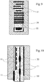
- a fully assembled vehicle wheel 8 is shown in cross section. This is composed of a pneumatic vehicle tire 1 and a rim 7 receiving the pneumatic vehicle tire 1.
- the pneumatic vehicle tire 1 in turn consists of a profiled tread 2 whose profile in the illustration in FIG. 1 is merely indicated by a plurality of groove-like depressions. Below this tread 2, the pneumatic vehicle tire 1 has a plurality of belt layers 15, which in the FIG. 1 are also shown only hinted.
- On both sides of the tread 2 of the vehicle pneumatic tire 1 is also in each case a side wall 3 and 4, whose lower end is formed in each case by a tire bead 5 and 6, respectively.
- Each tire bead 5, 6 consists of a bead core 19, which merges into a core profile 18, which is covered with a rubber material.
- the tire beads 5, 6 of the pneumatic vehicle tire 1 form a seal with respect to the surroundings, so that they lie airtight against a rim edge 14 of the rim 7.
- the pneumatic vehicle tire 1 and the rim 7 thereby jointly surround an air cavity 21 which is filled with compressed air via the valve 12 of the vehicle wheel 8 inserted into a valve stem 13.
- the side walls 3, 4 of the pneumatic vehicle tire 1 are composed in a conventional manner of several layers and thereby form a complex system for stabilizing the pneumatic vehicle tire 1.
- each side wall 3 4 initially a reinforcing profile 16 is present, to the in the direction of the outside of each side wall 3, 4 a carcass 17 connects, which in turn in one in the FIG. 1 unspecified Rubber layer is embedded.
- the side wall may contain additional individual layers, which will not be discussed here.
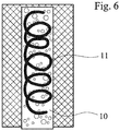
- the feature of the invention which consists in that on the tread 2 opposite inner surface 9 of the vehicle pneumatic tire 1, an absorber 10 is arranged. This absorber 10 is adhesively bonded to the inner surface 9 of the pneumatic vehicle tire 1 using an adhesive 11. As hinted at from the representation in FIG.
- the adhesive 11 in the present case has several interruptions and has been applied in the circumferential direction of the pneumatic vehicle tire 1 in a line on the inner surface 9 of the vehicle pneumatic tire 1, before the absorber 10 has been placed with a corresponding adhesive surface on the inner surface 9.
- FIG. 2 1 illustrates a wavy line shape of the adhesive 11 in the direction of the circumference of the pneumatic vehicle tire 1, in which the wavy lines of the adhesive 11 partially have an approximately sinusoidal shape and partially deviate from the sinusoidal shape of the wavy line geometry.
- FIG. 3 From the FIG. 3 is a zigzag-shaped or sawtooth-like arrangement of the adhesive 11 in the circumferential direction of the pneumatic vehicle tire 1 forth. Also here are Sections with uniform intervals of the individual geometries as well as sections with changing distances of the individual geometries of the adhesive 11th
- FIG. 4 A particular pattern of the arrangement of the adhesive 11 is shown in FIG. 4 ,
- the adhesive 11 was applied in strips, wherein viewed through the different thickness and the different distances of the individual adhesive strips 11 in the circumferential direction of the pneumatic vehicle tire 1, a barcode-like geometry is formed.
- FIG. 5 Various variations of a dot matrix are shown, wherein both a plurality of smaller dots can be provided in random or uniform arrangement, as well as a small number, in their geometry enlarged points of the adhesive 11 in uniform or non-uniform intervals. Likewise, with such a dot matrix and the volume of the adhesive application can be varied.
- FIG. 6 FIG. 10 illustrates a serpentine or spiral shape of the adhesive 11 along the circumferential direction of the pneumatic vehicle tire 1.
- FIG. 7 shows, viewed in the circumferential direction of the pneumatic vehicle tire 1, again a wavy line form of the adhesive 11, in which case interruptions in the lines of the adhesive 11 are present.
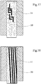
- FIG. 9 again shows a striped pattern, the individual strips are aligned transversely to the circumferential direction of the pneumatic vehicle tire 1 and partially laterally beyond the adhesive surface of the absorber 10 go.
- the bar-code-like pattern of the line of the adhesive 11 in FIG. 9 different distances between the lines and partially shows a lateral offset of the lines of the adhesive 11 to each other.
- FIG. 2 illustrates a widened region of the adhesive 11 which is located in the region of the abutting edges of the absorber 10 is provided, that is, on the surfaces of the absorber 10, which come to rest after its introduction into the pneumatic vehicle tire 1.
- FIG. 10 Various possibilities of execution of a strip pattern in the circumferential direction of the pneumatic vehicle tire 1 can be removed. These may have different, lateral distances from one another, have thickenings 22, also be applied beyond the adhesive surface of the absorber 10 and / or have interruptions.
- the one in the right part of the picture FIG. 10 recognizable strip of adhesive 11 goes laterally beyond the edge region of the absorber 10 and is executed in this section completely continuous, which has the essential advantage that this critical, prone to detaching edge region of the absorber 10 in a special way on the inner surface 9 of the pneumatic vehicle tire. 1 is fixed.
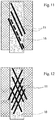
- FIG. 11 Another example of the lines of the adhesive 11 goes from the FIG. 11 out.
- the lines of the adhesive 11 along the inner surface 9 of the vehicle pneumatic tire 1 were inclined, ie at an angle to the circumferential direction of the pneumatic vehicle tire 1, respectively. It also follows from this illustration that the distances between the lines of the adhesive 11 can be of different widths and furthermore interruptions within the lines are possible.
- FIG. 12 shows a crosswise arrangement of the lines of the adhesive 11 with partially varying distances from one another.
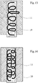
- FIG. 13 illustrates once again a serpentine shape of the adhesive 11 along the inner surface 9 of the pneumatic vehicle tire 1. It is a peculiarity that the line follows no special geometry and beyond parts of the line of adhesive 11 are applied beyond the edge of the absorber addition.
- a plurality of serpentine forms of the adhesive 11 can be provided side by side.
- Exemplary is from the FIG. 15
- a combination of a dot pattern with karo or cuboid geometries of the adhesive 11 can be seen, wherein the individual patterns of the adhesive 11 can also be used separately and not necessarily the illustrated combination must be used.
- FIG. 16 moreover shows a special feature, which consists in that in the side regions of the absorber 10 each thickenings 22 are provided which ensure improved adhesion in the edge region of the absorber 10 with the pneumatic vehicle tire 1.
- FIG. 18 once again an oblique line of the adhesive 11, are used in the continuous lines, the lateral distances vary from one another.
Landscapes
- Engineering & Computer Science (AREA)
- Mechanical Engineering (AREA)
- Tires In General (AREA)
- Adhesives Or Adhesive Processes (AREA)
Claims (10)
- Pneumatique de véhicule (1) dont la bande de roulement profilée (2) se transforme des deux côtés en des parois latérales (3, 4) dont l'extrémité est formée par un talon de pneumatique (5, 6) qui peut être inséré de manière étanche à l'air dans une jante (7) d'une roue de véhicule (8), un absorbeur (10) relié par une liaison de matière à la surface intérieure (9) du pneumatique de véhicule (1) étant intégré dans le pneumatique de véhicule (1) pour réaliser une absorption acoustique,
caractérisé en ce que
la liaison de matière comprend un activateur d'adhérence (11) qui est disposé sans être totalement réparti entre l'absorbeur (10) et la surface intérieure (9) du pneumatique pour véhicule (1) et qui présente une distribution variable non uniforme sur l'étendue de la surface intérieure (9) du pneumatique de véhicule (1) . - Pneumatique de véhicule selon l'une des revendications précédentes,
caractérisé en ce que
l'activateur d'adhérence (11) comprend un motif à rayures, a une forme de lignes ondulées ou forme une matrice de points. - Pneumatique de véhicule selon l'une des revendications précédentes,
caractérisé en ce que
le volume et/ou la largeur de l'activateur d'adhérence (11) présente une distribution uniforme ou variable sur l'étendue de la surface intérieure (9) et/ou dans la direction transversale à l'étendue de la surface intérieure (9) du pneumatique de véhicule (1). - Pneumatique de véhicule selon l'une des revendications précédentes,
caractérisé en ce que
toute la surface adhésive située entre la surface intérieure (9) du pneumatique de véhicule (1) et l'absorbeur (10) est comprise entre 10 % et 90 % de la surface projetée de l'absorbeur (10). - Pneumatique de véhicule selon l'une des revendications 1 à 3,
caractérisé en ce que
toute la surface adhésive située entre la surface intérieure (9) du pneumatique de véhicule (1) et l'absorbeur (10) est comprise entre 30 % et 70 % de la surface projetée de l'absorbeur (10). - Pneumatique de véhicule selon l'une des revendications 1 à 3,
caractérisé en ce que
toute la surface adhésive située entre la surface intérieure (9) du pneumatique de véhicule (1) et l'absorbeur (10) est comprise entre 40 % et 50 % de la surface projetée de l'absorbeur (10). - Pneumatique de véhicule selon l'une des revendications précédentes,
caractérisé en ce que
l'activateur d'adhérence (11) est un adhésif. - Pneumatique de véhicule selon l'une des revendications précédentes,
caractérisé en ce que
l'activateur d'adhérence (11) est appliqué à l'intérieur de la surface projetée de l'absorbeur (10) et au-delà. - Pneumatique de véhicule selon l'une des revendications précédentes,
caractérisé en ce que
l'activateur d'adhérence (11) est un gel de polyuréthane. - Pneumatique de véhicule selon l'une des revendications précédentes,
caractérisé en ce que
le rapport f(x) de la surface d'activateur d'adhérence à la surface projetée sur chaque surface partielle X*Y a la fonction suivante :


Applications Claiming Priority (2)
| Application Number | Priority Date | Filing Date | Title |
|---|---|---|---|
| DE102015215738.5A DE102015215738A1 (de) | 2015-08-18 | 2015-08-18 | Fahrzeugluftreifen |
| PCT/EP2016/057961 WO2017028962A1 (fr) | 2015-08-18 | 2016-04-12 | Pneumatique de véhicule |
Publications (2)
| Publication Number | Publication Date |
|---|---|
| EP3337680A1 EP3337680A1 (fr) | 2018-06-27 |
| EP3337680B1 true EP3337680B1 (fr) | 2019-10-30 |
Family
ID=55701991
Family Applications (1)
| Application Number | Title | Priority Date | Filing Date |
|---|---|---|---|
| EP16715554.8A Active EP3337680B1 (fr) | 2015-08-18 | 2016-04-12 | Pneumatique |
Country Status (5)
| Country | Link |
|---|---|
| US (1) | US20180236823A1 (fr) |
| EP (1) | EP3337680B1 (fr) |
| JP (1) | JP6646728B2 (fr) |
| DE (1) | DE102015215738A1 (fr) |
| WO (1) | WO2017028962A1 (fr) |
Families Citing this family (13)
| Publication number | Priority date | Publication date | Assignee | Title |
|---|---|---|---|---|
| CN107407097B (zh) | 2014-12-08 | 2020-11-13 | 泽菲罗斯公司 | 垂直铺网纤维地板 |
| CN107206732B (zh) | 2015-01-20 | 2021-02-26 | 泽菲罗斯公司 | 镀铝表面的非纺织材料 |
| WO2016187526A1 (fr) | 2015-05-20 | 2016-11-24 | Zephyros, Inc. | Composite multi-impédance |
| CN109562645B (zh) | 2016-08-02 | 2020-12-18 | 横滨橡胶株式会社 | 泄气保用轮胎 |
| JP7238562B2 (ja) * | 2019-04-11 | 2023-03-14 | 横浜ゴム株式会社 | 空気入りタイヤ |
| GB2599820B (en) * | 2019-07-03 | 2023-04-26 | Murata Manufacturing Co | Fluid control apparatus |
| US20230166566A1 (en) * | 2020-04-24 | 2023-06-01 | Apollo Tyres Global R&D B. V. | Pneumatic tyre |
| JP7595455B2 (ja) * | 2020-12-22 | 2024-12-06 | Toyo Tire株式会社 | 空気入りタイヤの製造方法 |
| JP7684043B2 (ja) * | 2020-12-22 | 2025-05-27 | Toyo Tire株式会社 | 空気入りタイヤ、および空気入りタイヤの製造方法 |
| KR102598497B1 (ko) * | 2021-09-27 | 2023-11-07 | 넥센타이어 주식회사 | 타이어 |
| JP2023096611A (ja) * | 2021-12-27 | 2023-07-07 | Toyo Tire株式会社 | 空気入りタイヤ |
| JP2024061153A (ja) * | 2022-10-21 | 2024-05-07 | 住友ゴム工業株式会社 | 空気入りタイヤ |
| DE102024207644A1 (de) * | 2024-08-12 | 2026-02-12 | Continental Reifen Deutschland Gmbh | Fahrzeugreifen und Verfahren |
Family Cites Families (10)
| Publication number | Priority date | Publication date | Assignee | Title |
|---|---|---|---|---|
| DE19806953C2 (de) | 1998-02-19 | 2000-03-02 | Dornier Gmbh Lindauer | Schneideinrichtung in Webmaschinen |
| WO2003103989A1 (fr) * | 2002-06-05 | 2003-12-18 | 住友ゴム工業株式会社 | Ensemble pneumatique-jante, element insonorisant utilise avec cet ensemble et procede de stockage de pneumatiques |
| JP4153371B2 (ja) * | 2003-06-09 | 2008-09-24 | 住友ゴム工業株式会社 | 空気入りタイヤとリムとの組立体 |
| JP4113084B2 (ja) * | 2003-09-30 | 2008-07-02 | 東海ゴム工業株式会社 | 防音タイヤ |
| JP4299813B2 (ja) * | 2005-07-20 | 2009-07-22 | 住友ゴム工業株式会社 | 空気入りタイヤ |
| DE102007028932A1 (de) * | 2007-06-22 | 2008-12-24 | Continental Aktiengesellschaft | Fahrzeugluftreifen |
| US20130032262A1 (en) * | 2011-08-02 | 2013-02-07 | Bormann Rene Louis | Tire with foamed noise damper |
| DE102011053686A1 (de) * | 2011-09-16 | 2013-03-21 | Continental Reifen Deutschland Gmbh | Fahrzeugluftreifen |
| DE112014005308T5 (de) * | 2013-11-21 | 2016-08-04 | The Yokohama Rubber Co., Ltd. | Luftreifen |
| US20160303923A1 (en) * | 2013-12-03 | 2016-10-20 | The Yokohama Rubber Co., Ltd. | Method for Manufacturing Pneumatic Tire |
-
2015
- 2015-08-18 DE DE102015215738.5A patent/DE102015215738A1/de not_active Withdrawn
-
2016
- 2016-04-12 US US15/752,744 patent/US20180236823A1/en not_active Abandoned
- 2016-04-12 WO PCT/EP2016/057961 patent/WO2017028962A1/fr not_active Ceased
- 2016-04-12 EP EP16715554.8A patent/EP3337680B1/fr active Active
- 2016-04-12 JP JP2018506345A patent/JP6646728B2/ja active Active
Non-Patent Citations (1)
| Title |
|---|
| None * |
Also Published As
| Publication number | Publication date |
|---|---|
| EP3337680A1 (fr) | 2018-06-27 |
| DE102015215738A1 (de) | 2017-02-23 |
| WO2017028962A1 (fr) | 2017-02-23 |
| JP2018527232A (ja) | 2018-09-20 |
| US20180236823A1 (en) | 2018-08-23 |
| JP6646728B2 (ja) | 2020-02-14 |
Similar Documents
| Publication | Publication Date | Title |
|---|---|---|
| EP3337680B1 (fr) | Pneumatique | |
| EP1094957A1 (fr) | Roue de vehicule automobile comportant un corps d'appui pour roulement de secours | |
| DE69904634T2 (de) | Reifen und dessen lauffläche | |
| EP3325285B1 (fr) | Pneumatique de véhicule | |
| EP3383668B1 (fr) | Pneumatique de véhicule | |
| DE102015115774B4 (de) | Luftreifen für ein Kraftfahrzeug | |
| DE60010833T2 (de) | Laufflächenprofil | |
| DE102006002455B4 (de) | Luftreifen | |
| DE2739597C2 (de) | Kraftfahrzeugrad | |
| DE60106927T2 (de) | Oberflächenprofil von Profilelementen einer Luftreifenlauffläche | |
| EP3337681B1 (fr) | Pneumatique | |
| DE102015212874A1 (de) | Fahrzeugluftreifen | |
| WO2017028963A1 (fr) | Pneumatique de véhicule | |
| WO2016078783A1 (fr) | Pneumatique de véhicule | |
| DE2744848C2 (fr) | ||
| DE102012103946A1 (de) | Laufstreifenprofil eines Fahrzeugreifens | |
| EP3319819B1 (fr) | Roue de véhicule comprenant un milieu absorbant le son et procédé d'introduction du milieu dans la roue de véhicule | |
| DE4209687A1 (de) | Reifen für ein Fahrzeug, insbesondere für ein Kraftfahrzeug sowie Verfahren zu dessen Herstellung | |
| DE102007026814A1 (de) | Fahrzeugluftreifen | |
| DE1009953B (de) | Gummilaufflaeche, insbesondere fuer Fahrzeugreifen | |
| EP3390112B1 (fr) | Pneumatique de véhicule avec crampons | |
| DE2414885A1 (de) | Mit einem luftreifen versehene felge, insbesondere fuer kraftfahrzeuge | |
| DE4310714A1 (de) | Luftreifen | |
| DE2922588A1 (de) | Rad | |
| DE3500894A1 (de) | Reifen |
Legal Events
| Date | Code | Title | Description |
|---|---|---|---|
| STAA | Information on the status of an ep patent application or granted ep patent |
Free format text: STATUS: THE INTERNATIONAL PUBLICATION HAS BEEN MADE |
|
| PUAI | Public reference made under article 153(3) epc to a published international application that has entered the european phase |
Free format text: ORIGINAL CODE: 0009012 |
|
| STAA | Information on the status of an ep patent application or granted ep patent |
Free format text: STATUS: REQUEST FOR EXAMINATION WAS MADE |
|
| 17P | Request for examination filed |
Effective date: 20180319 |
|
| AK | Designated contracting states |
Kind code of ref document: A1 Designated state(s): AL AT BE BG CH CY CZ DE DK EE ES FI FR GB GR HR HU IE IS IT LI LT LU LV MC MK MT NL NO PL PT RO RS SE SI SK SM TR |
|
| AX | Request for extension of the european patent |
Extension state: BA ME |
|
| DAV | Request for validation of the european patent (deleted) | ||
| DAX | Request for extension of the european patent (deleted) | ||
| GRAP | Despatch of communication of intention to grant a patent |
Free format text: ORIGINAL CODE: EPIDOSNIGR1 |
|
| STAA | Information on the status of an ep patent application or granted ep patent |
Free format text: STATUS: GRANT OF PATENT IS INTENDED |
|
| INTG | Intention to grant announced |
Effective date: 20190705 |
|
| GRAS | Grant fee paid |
Free format text: ORIGINAL CODE: EPIDOSNIGR3 |
|
| GRAA | (expected) grant |
Free format text: ORIGINAL CODE: 0009210 |
|
| STAA | Information on the status of an ep patent application or granted ep patent |
Free format text: STATUS: THE PATENT HAS BEEN GRANTED |
|
| AK | Designated contracting states |
Kind code of ref document: B1 Designated state(s): AL AT BE BG CH CY CZ DE DK EE ES FI FR GB GR HR HU IE IS IT LI LT LU LV MC MK MT NL NO PL PT RO RS SE SI SK SM TR |
|
| REG | Reference to a national code |
Ref country code: GB Ref legal event code: FG4D Free format text: NOT ENGLISH |
|
| REG | Reference to a national code |
Ref country code: CH Ref legal event code: EP |
|
| REG | Reference to a national code |
Ref country code: DE Ref legal event code: R096 Ref document number: 502016007314 Country of ref document: DE |
|
| REG | Reference to a national code |
Ref country code: AT Ref legal event code: REF Ref document number: 1195734 Country of ref document: AT Kind code of ref document: T Effective date: 20191115 |
|
| REG | Reference to a national code |
Ref country code: IE Ref legal event code: FG4D Free format text: LANGUAGE OF EP DOCUMENT: GERMAN |
|
| REG | Reference to a national code |
Ref country code: LT Ref legal event code: MG4D |
|
| PG25 | Lapsed in a contracting state [announced via postgrant information from national office to epo] |
Ref country code: BG Free format text: LAPSE BECAUSE OF FAILURE TO SUBMIT A TRANSLATION OF THE DESCRIPTION OR TO PAY THE FEE WITHIN THE PRESCRIBED TIME-LIMIT Effective date: 20200130 Ref country code: GR Free format text: LAPSE BECAUSE OF FAILURE TO SUBMIT A TRANSLATION OF THE DESCRIPTION OR TO PAY THE FEE WITHIN THE PRESCRIBED TIME-LIMIT Effective date: 20200131 Ref country code: PL Free format text: LAPSE BECAUSE OF FAILURE TO SUBMIT A TRANSLATION OF THE DESCRIPTION OR TO PAY THE FEE WITHIN THE PRESCRIBED TIME-LIMIT Effective date: 20191030 Ref country code: NO Free format text: LAPSE BECAUSE OF FAILURE TO SUBMIT A TRANSLATION OF THE DESCRIPTION OR TO PAY THE FEE WITHIN THE PRESCRIBED TIME-LIMIT Effective date: 20200130 Ref country code: NL Free format text: LAPSE BECAUSE OF FAILURE TO SUBMIT A TRANSLATION OF THE DESCRIPTION OR TO PAY THE FEE WITHIN THE PRESCRIBED TIME-LIMIT Effective date: 20191030 Ref country code: LT Free format text: LAPSE BECAUSE OF FAILURE TO SUBMIT A TRANSLATION OF THE DESCRIPTION OR TO PAY THE FEE WITHIN THE PRESCRIBED TIME-LIMIT Effective date: 20191030 Ref country code: PT Free format text: LAPSE BECAUSE OF FAILURE TO SUBMIT A TRANSLATION OF THE DESCRIPTION OR TO PAY THE FEE WITHIN THE PRESCRIBED TIME-LIMIT Effective date: 20200302 Ref country code: SE Free format text: LAPSE BECAUSE OF FAILURE TO SUBMIT A TRANSLATION OF THE DESCRIPTION OR TO PAY THE FEE WITHIN THE PRESCRIBED TIME-LIMIT Effective date: 20191030 Ref country code: LV Free format text: LAPSE BECAUSE OF FAILURE TO SUBMIT A TRANSLATION OF THE DESCRIPTION OR TO PAY THE FEE WITHIN THE PRESCRIBED TIME-LIMIT Effective date: 20191030 Ref country code: FI Free format text: LAPSE BECAUSE OF FAILURE TO SUBMIT A TRANSLATION OF THE DESCRIPTION OR TO PAY THE FEE WITHIN THE PRESCRIBED TIME-LIMIT Effective date: 20191030 |
|
| REG | Reference to a national code |
Ref country code: NL Ref legal event code: MP Effective date: 20191030 |
|
| PG25 | Lapsed in a contracting state [announced via postgrant information from national office to epo] |
Ref country code: IS Free format text: LAPSE BECAUSE OF FAILURE TO SUBMIT A TRANSLATION OF THE DESCRIPTION OR TO PAY THE FEE WITHIN THE PRESCRIBED TIME-LIMIT Effective date: 20200229 Ref country code: RS Free format text: LAPSE BECAUSE OF FAILURE TO SUBMIT A TRANSLATION OF THE DESCRIPTION OR TO PAY THE FEE WITHIN THE PRESCRIBED TIME-LIMIT Effective date: 20191030 Ref country code: HR Free format text: LAPSE BECAUSE OF FAILURE TO SUBMIT A TRANSLATION OF THE DESCRIPTION OR TO PAY THE FEE WITHIN THE PRESCRIBED TIME-LIMIT Effective date: 20191030 |
|
| PG25 | Lapsed in a contracting state [announced via postgrant information from national office to epo] |
Ref country code: AL Free format text: LAPSE BECAUSE OF FAILURE TO SUBMIT A TRANSLATION OF THE DESCRIPTION OR TO PAY THE FEE WITHIN THE PRESCRIBED TIME-LIMIT Effective date: 20191030 |
|
| PG25 | Lapsed in a contracting state [announced via postgrant information from national office to epo] |
Ref country code: ES Free format text: LAPSE BECAUSE OF FAILURE TO SUBMIT A TRANSLATION OF THE DESCRIPTION OR TO PAY THE FEE WITHIN THE PRESCRIBED TIME-LIMIT Effective date: 20191030 Ref country code: DK Free format text: LAPSE BECAUSE OF FAILURE TO SUBMIT A TRANSLATION OF THE DESCRIPTION OR TO PAY THE FEE WITHIN THE PRESCRIBED TIME-LIMIT Effective date: 20191030 Ref country code: CZ Free format text: LAPSE BECAUSE OF FAILURE TO SUBMIT A TRANSLATION OF THE DESCRIPTION OR TO PAY THE FEE WITHIN THE PRESCRIBED TIME-LIMIT Effective date: 20191030 Ref country code: EE Free format text: LAPSE BECAUSE OF FAILURE TO SUBMIT A TRANSLATION OF THE DESCRIPTION OR TO PAY THE FEE WITHIN THE PRESCRIBED TIME-LIMIT Effective date: 20191030 Ref country code: RO Free format text: LAPSE BECAUSE OF FAILURE TO SUBMIT A TRANSLATION OF THE DESCRIPTION OR TO PAY THE FEE WITHIN THE PRESCRIBED TIME-LIMIT Effective date: 20191030 |
|
| REG | Reference to a national code |
Ref country code: DE Ref legal event code: R097 Ref document number: 502016007314 Country of ref document: DE |
|
| PG25 | Lapsed in a contracting state [announced via postgrant information from national office to epo] |
Ref country code: SK Free format text: LAPSE BECAUSE OF FAILURE TO SUBMIT A TRANSLATION OF THE DESCRIPTION OR TO PAY THE FEE WITHIN THE PRESCRIBED TIME-LIMIT Effective date: 20191030 Ref country code: SM Free format text: LAPSE BECAUSE OF FAILURE TO SUBMIT A TRANSLATION OF THE DESCRIPTION OR TO PAY THE FEE WITHIN THE PRESCRIBED TIME-LIMIT Effective date: 20191030 Ref country code: IT Free format text: LAPSE BECAUSE OF FAILURE TO SUBMIT A TRANSLATION OF THE DESCRIPTION OR TO PAY THE FEE WITHIN THE PRESCRIBED TIME-LIMIT Effective date: 20191030 |
|
| PLBE | No opposition filed within time limit |
Free format text: ORIGINAL CODE: 0009261 |
|
| STAA | Information on the status of an ep patent application or granted ep patent |
Free format text: STATUS: NO OPPOSITION FILED WITHIN TIME LIMIT |
|
| 26N | No opposition filed |
Effective date: 20200731 |
|
| PG25 | Lapsed in a contracting state [announced via postgrant information from national office to epo] |
Ref country code: MC Free format text: LAPSE BECAUSE OF FAILURE TO SUBMIT A TRANSLATION OF THE DESCRIPTION OR TO PAY THE FEE WITHIN THE PRESCRIBED TIME-LIMIT Effective date: 20191030 Ref country code: SI Free format text: LAPSE BECAUSE OF FAILURE TO SUBMIT A TRANSLATION OF THE DESCRIPTION OR TO PAY THE FEE WITHIN THE PRESCRIBED TIME-LIMIT Effective date: 20191030 |
|
| REG | Reference to a national code |
Ref country code: CH Ref legal event code: PL |
|
| PG25 | Lapsed in a contracting state [announced via postgrant information from national office to epo] |
Ref country code: LI Free format text: LAPSE BECAUSE OF NON-PAYMENT OF DUE FEES Effective date: 20200430 Ref country code: LU Free format text: LAPSE BECAUSE OF NON-PAYMENT OF DUE FEES Effective date: 20200412 Ref country code: CH Free format text: LAPSE BECAUSE OF NON-PAYMENT OF DUE FEES Effective date: 20200430 |
|
| REG | Reference to a national code |
Ref country code: BE Ref legal event code: MM Effective date: 20200430 |
|
| PG25 | Lapsed in a contracting state [announced via postgrant information from national office to epo] |
Ref country code: BE Free format text: LAPSE BECAUSE OF NON-PAYMENT OF DUE FEES Effective date: 20200430 |
|
| GBPC | Gb: european patent ceased through non-payment of renewal fee |
Effective date: 20200412 |
|
| PG25 | Lapsed in a contracting state [announced via postgrant information from national office to epo] |
Ref country code: IE Free format text: LAPSE BECAUSE OF NON-PAYMENT OF DUE FEES Effective date: 20200412 Ref country code: GB Free format text: LAPSE BECAUSE OF NON-PAYMENT OF DUE FEES Effective date: 20200412 |
|
| PG25 | Lapsed in a contracting state [announced via postgrant information from national office to epo] |
Ref country code: TR Free format text: LAPSE BECAUSE OF FAILURE TO SUBMIT A TRANSLATION OF THE DESCRIPTION OR TO PAY THE FEE WITHIN THE PRESCRIBED TIME-LIMIT Effective date: 20191030 Ref country code: MT Free format text: LAPSE BECAUSE OF FAILURE TO SUBMIT A TRANSLATION OF THE DESCRIPTION OR TO PAY THE FEE WITHIN THE PRESCRIBED TIME-LIMIT Effective date: 20191030 Ref country code: CY Free format text: LAPSE BECAUSE OF FAILURE TO SUBMIT A TRANSLATION OF THE DESCRIPTION OR TO PAY THE FEE WITHIN THE PRESCRIBED TIME-LIMIT Effective date: 20191030 |
|
| REG | Reference to a national code |
Ref country code: AT Ref legal event code: MM01 Ref document number: 1195734 Country of ref document: AT Kind code of ref document: T Effective date: 20210412 |
|
| PG25 | Lapsed in a contracting state [announced via postgrant information from national office to epo] |
Ref country code: MK Free format text: LAPSE BECAUSE OF FAILURE TO SUBMIT A TRANSLATION OF THE DESCRIPTION OR TO PAY THE FEE WITHIN THE PRESCRIBED TIME-LIMIT Effective date: 20191030 |
|
| PG25 | Lapsed in a contracting state [announced via postgrant information from national office to epo] |
Ref country code: AT Free format text: LAPSE BECAUSE OF NON-PAYMENT OF DUE FEES Effective date: 20210412 |
|
| REG | Reference to a national code |
Ref country code: DE Ref legal event code: R081 Ref document number: 502016007314 Country of ref document: DE Owner name: CONTINENTAL REIFEN DEUTSCHLAND GMBH, DE Free format text: FORMER OWNER: CONTINENTAL REIFEN DEUTSCHLAND GMBH, 30165 HANNOVER, DE |
|
| PGFP | Annual fee paid to national office [announced via postgrant information from national office to epo] |
Ref country code: DE Payment date: 20250430 Year of fee payment: 10 |
|
| PGFP | Annual fee paid to national office [announced via postgrant information from national office to epo] |
Ref country code: FR Payment date: 20250425 Year of fee payment: 10 |