EP3337740B1 - Appareil et procédé de manipulation de cones d'emballage - Google Patents
Appareil et procédé de manipulation de cones d'emballage Download PDFInfo
- Publication number
- EP3337740B1 EP3337740B1 EP16742308.6A EP16742308A EP3337740B1 EP 3337740 B1 EP3337740 B1 EP 3337740B1 EP 16742308 A EP16742308 A EP 16742308A EP 3337740 B1 EP3337740 B1 EP 3337740B1
- Authority
- EP
- European Patent Office
- Prior art keywords
- cone
- chamber
- circular opening
- sleeves
- circumference
- Prior art date
- Legal status (The legal status is an assumption and is not a legal conclusion. Google has not performed a legal analysis and makes no representation as to the accuracy of the status listed.)
- Not-in-force
Links
Images

Classifications
-
- B—PERFORMING OPERATIONS; TRANSPORTING
- B65—CONVEYING; PACKING; STORING; HANDLING THIN OR FILAMENTARY MATERIAL
- B65G—TRANSPORT OR STORAGE DEVICES, e.g. CONVEYORS FOR LOADING OR TIPPING, SHOP CONVEYOR SYSTEMS OR PNEUMATIC TUBE CONVEYORS
- B65G59/00—De-stacking of articles
-
- A—HUMAN NECESSITIES
- A23—FOODS OR FOODSTUFFS; TREATMENT THEREOF, NOT COVERED BY OTHER CLASSES
- A23G—COCOA; COCOA PRODUCTS, e.g. CHOCOLATE; SUBSTITUTES FOR COCOA OR COCOA PRODUCTS; CONFECTIONERY; CHEWING GUM; ICE-CREAM; PREPARATION THEREOF
- A23G7/00—Other apparatus or process specially adapted for the chocolate or confectionery industry
- A23G7/0025—Apparatus for stacking or unstacking, e.g. stacking of chocolate, confectionery, moulds, trays, except stacking of sticks
-
- A—HUMAN NECESSITIES
- A23—FOODS OR FOODSTUFFS; TREATMENT THEREOF, NOT COVERED BY OTHER CLASSES
- A23G—COCOA; COCOA PRODUCTS, e.g. CHOCOLATE; SUBSTITUTES FOR COCOA OR COCOA PRODUCTS; CONFECTIONERY; CHEWING GUM; ICE-CREAM; PREPARATION THEREOF
- A23G7/00—Other apparatus or process specially adapted for the chocolate or confectionery industry
- A23G7/0043—Other processes specially adapted for the chocolate or confectionery industry
- A23G7/005—General processes
- A23G7/0075—Processes for stacking or unstacking, e.g. stacking of chocolate, confectionery, moulds, trays, except for sticks
-
- B—PERFORMING OPERATIONS; TRANSPORTING
- B65—CONVEYING; PACKING; STORING; HANDLING THIN OR FILAMENTARY MATERIAL
- B65G—TRANSPORT OR STORAGE DEVICES, e.g. CONVEYORS FOR LOADING OR TIPPING, SHOP CONVEYOR SYSTEMS OR PNEUMATIC TUBE CONVEYORS
- B65G59/00—De-stacking of articles
- B65G59/10—De-stacking nested articles
-
- A—HUMAN NECESSITIES
- A47—FURNITURE; DOMESTIC ARTICLES OR APPLIANCES; COFFEE MILLS; SPICE MILLS; SUCTION CLEANERS IN GENERAL
- A47F—SPECIAL FURNITURE, FITTINGS, OR ACCESSORIES FOR SHOPS, STOREHOUSES, BARS, RESTAURANTS OR THE LIKE; PAYING COUNTERS
- A47F1/00—Racks for dispensing merchandise; Containers for dispensing merchandise
- A47F1/04—Racks or containers with arrangements for dispensing articles, e.g. by means of gravity or springs
- A47F1/08—Racks or containers with arrangements for dispensing articles, e.g. by means of gravity or springs dispensing from bottom
- A47F1/10—Racks or containers with arrangements for dispensing articles, e.g. by means of gravity or springs dispensing from bottom having mechanical dispensing means, e.g. with buttons or handles
- A47F1/106—Racks or containers with arrangements for dispensing articles, e.g. by means of gravity or springs dispensing from bottom having mechanical dispensing means, e.g. with buttons or handles for nested articles, e.g. cups, cones
Definitions
- the present invention relates to an apparatus and process for handling cone sleeves.
- the invention relates to an apparatus and process for handling sleeves for ice cream cones.
- Ice cream cone products such as Cornetto are well known and popular with consumers. Such products comprise a wafer cone, typically coated on the inside with a chocolate-based material, and filled with a frozen confection.
- These cones are typical ice cream cones with an opening at one end tapering to a point at the other. More specifically these cones are hollow conical three-dimensional objects with a circular opening at one end into which the frozen confection is introduced and at the other end the wall of the cone terminates at the tip of these cones. The walls of these cones taper in a substantially straight line from the circular opening to the tip.
- Products such as Cornettos are provided in a sleeve in which the cone sits that is usually made from a paper-based material such as coated paper based material or multi-layered paper material.
- the sleeve serves to support and protect the cone and its contents during production and also protects the final product in the supply chain. During consumption the sleeve also provides a holder for consumers, allowing them to eat the product without necessarily making contact with the cone itself.
- Cone sleeves are normally made from a blank which, prior to rolling, has a shape akin to an isosceles triangle but where the third edge is a curve. More specifically such a blank has the form of a circular sector which can be described by taking two lines from the centre of a circle out to the edge. These lines form two edges of the circular sector and each have a length equal to the radius of the circle. The other edge of the sector is the arc of the circle between the two lines. The central angle ⁇ of the sector is the angle formed between the two lines where they meet at the centre of the circle.
- a sector with a central angle of 180° is a semicircle, quadrants have a central angle of 90°, sextants have a central angle of 60°, and octants have a central angle of 45°.
- quadrants have a central angle of 90°
- sextants have a central angle of 60°
- octants have a central angle of 45°.
- cone sleeves are usually provided as nested stacks wherein a multitude of cone sleeves are produced, one inside another and then delivered to the point of manufacture of the ice cream cone products.
- Round tipped cones are one such cone shape.
- the cone does not have a point where the wall of the cone terminates. Instead, the cone has a large, rounded tip.
- Standard sleeve blanks, the resulting sleeves, and the associated sleeve forming apparatuses and processes are all directed towards forming traditional cone sleeves having a pointed tip.
- Such sleeves are unsuitable for round tipped cones.
- a round tipped cone is placed in a standard cone sleeve the rounded tip of the cone will not extend to the tip of the sleeve and there will be a void at the bottom of the sleeve.
- the tip of the cone sleeve is therefore not filled with the tip of a cone and is easily damaged during manufacture, transport and storage. Furthermore, the visual cue of the round tipped cone which has been carefully manufactured will be completely hidden if a standard pointed cone sleeve is used.
- WO2013/087801 therefore provides a process for the preparation of an ice cream cone sleeve with a rounded tip comprising the steps of: a) providing a forming element having the shape of a round tipped ice cream cone with a cone angle ⁇ and also providing a forming cavity having an internal surface corresponding to the shape of the forming element, b) placing a cone sleeve having a cone angle ⁇ within the forming cavity, c) engaging the forming element within the cone sleeve, and d) forcing the forming element and the forming cavity together wherein the cone sleeve has a frustoconical shape and an open tip and wherein the end of the sleeve protrudes beyond the end of the forming element in step c).
- round tipped cone sleeves do not have the pointed tip of standard cone sleeves. With such standard cone sleeves, the ends of the pointed tips tend to engage one inside another in the stack and to some extent prevent the sleeves from packing any more tightly in the nested stack. In contrast, round tipped cone sleeves do not have pointed tips and the round tipped sleeves are therefore even more capable of tightly packing together and a vacuum forms both at the wall area and at the rounded tip. As a consequence, the issues of denesting are even more prevalent with round tipped items. It is also the case that the round tipped cone sleeves of WO2013/087801 are produced from precursor cone sleeves that have a frustoconical shape and an open tip. These precursor cone sleeves are also provided in a nested stack and in the absence of any tip the packing of the these items is unfettered and they are especially prone to tight wedging and are particularly difficult to separate individually from a nested stack.
- US20020092791 discloses that a pressed container is formed having a peripheral sidewall, a continuous bottom wall along the lower edge of the sidewall, and an outwardly directed peripheral rim along the upper edge of the sidewall and wherein an inwardly directed bulge is provided along the upper edge of the sidewall and an outwardly directed bulge is provided along the upper edge of the sidewall that cooperates with the inwardly directed bulge of an adjacent container when stacked in nesting relationship to uniformly stack the containers in nested relationship for easy separation of the containers. It can therefore be appreciated that US20020092791 attempts to solve the problem of easy separation of the containers. However, it does so through structural changes to the items that are stacked whereas in the case of the cone sleeves of the present invention it is necessary to maintain the original shape that consumers demand.
- GB911724 discloses a device wherein cones from a tube fall to a lower pair of fingers which grip a lower lip of the cone and when a cycle of operations is initiated by inserting a coin a solenoid is energized to cause pins to open the lower fingers for release of the cones and to allow closure of upper fingers below an upper lip of the succeeding cone. When the lower jaws open then the bottom cone falls off under gravity.
- the cones and cone sleeves envisaged in the present invention do not have any lip features.
- GB1136968 discloses a device for drawing containers individually from a stack, the device comprising a gripping device with at least one clamping member moveable by air pressure variation to clamp and release side walls of the lowermost container.
- this device does not specifically address the issue of packed stacks of cone sleeves where the cone sleeves have become too tightly packed or even wedged together and although it provides a means to remove a container it does not ensure that one container is disengaged from another.
- US6048014 discloses a sanitary ice cream cone handling device that can have prongs or tines which can work in conjunction with a securing clip and a weight or plunger piece arrangement. This device is manually positioned beneath the stack and therefore is not suitable for automated manufacture. Moreover, any issues resulting from packed stacks of cone sleeves where the cone sleeves have become too tightly packed or even wedged together will have to be dealt with in a manual fashion by the operator.
- US1704695 discloses a device for dispensing ice cream cones, having: a base, a pair of cone supporting members mounted thereon, adapted to be moved toward each other to engage the exposed part of one cone in a nested stack of cones and assume the support thereof; springs whereby said members are so moved, a manually operable member whereby to separate said supporting members and allow said cone to drop, and means for arresting said dropping cone at a point which brings the next cone in the stack into position to receive similar support when said supporting members are again subjected to the action of said springs.
- this device is manually positioned beneath the stack and therefore is not suitable for automated manufacture, and any issues resulting from packed stacks of cone sleeves where the cone sleeves have become too tightly packed or even wedged together will have to be dealt with in a manual fashion by the operator.
- US2371668 discloses means by which jackets are fed from a magazine into carriages or holders, the holders brought to a loading station where cones are placed in the jackets, then the jackets are brought to their final positions and locked to the cones automatically, after which the jacketed cones are discharged from the machine into a suitable receptacle. It also discloses a set of feed elements or wipers having wings. These feed elements are preferably composed of rubber or other suitable resilient and yieldable substance.
- this device provides a means to remove a container it does not address the issue of packed stacks of cone sleeves where the cone sleeves have become too tightly packed or even wedged together and therefore the means do not ensure that one container is disengaged from another in such circumstances.
- GB1463274 discloses an apparatus whereby cones are released successively from the bottoms of each stack by an upper assembly of horizontally movable jaws, a lower assembly of jaws, and a downwardly and horizontally moving stripper assembly having stripper fingers.
- the stripper fingers engage with a lip on the cones to be separated.
- US3268116 discloses a method for feeding a flexible, open-top container from a substantially vertical nested stack of such containers onto a conveyor, the method comprising supporting the bottom container in said nested stack on opposite sides, attaching suction cups on opposite sides of said bottom container, the sides to which the suction cups are attached being different from the sides being supported, moving said suction cups slightly outwardly then inwardly insuring the release of any grip said bottom container may have on the stack of containers, pulling said suction cups downwardly to strip said last container from said stack of containers, releasing the suction in said suction cups, withdrawing said suction cups and allowing said container to drop freely onto a conveyor.
- this method requires that the containers are deformed in order to be removed. Such deformation may not be acceptable due to the potential damage to the sleeves and in any event it is difficult to balance adequate deformation such that the sleeves are denested against the potential to damage the sleeves when deforming them.
- US2445713 discloses a machine which comprises a magazine for the cones, a magazine for the jackets, a receiver for the jackets and cones, mechanism for removing the jackets, one at a time, from their magazine and placing them in the receiver.
- the mechanism for removing the jackets uses a plug having a bore with a lateral duct or port that terminates at a groove. When a jacket is sucked into the groove it deforms such that it can be removed from the stack. Again, this deformation may not be acceptable due to the potential damage to the sleeves and it is difficult to balance adequate deformation such that the sleeves are denested against the potential to damage the sleeves when deforming them.
- Certain separating devices employ pneumatic elements in the apparatus and / or processes used.
- GB2239450 discloses an apparatus for denesting a stack of containers, the apparatus comprising a first container engaging means, a second container engaging means, each of these means being a pair of opposed plates which is spaced from the first container engaging means in a direction which is, in use, substantially aligned with the stack, and drive means in the form of a cam arrangement for selectively and alternately moving the first and second container engaging means into and out of engagement with the stack whereby the first and second engaging means alternately hold an end container of the stack thereby to release a previous end container from the stack.
- a valve head is provided with air connection means which connect to opposed hollow upright rods of the magazine which are disposed substantially along the central line between the pairs of top and bottom plates.
- These hollow upright rods are provided with downwardly-inclined slots which are directed inwardly towards the centre and the bottom of the denester assembly and can act to cause radially inwardly and downwardly directed jets of air to assist in the denesting operation.
- the bottom container drops under the action of gravity and is blown down by air jets from slots out of the denester assembly. It can therefore be appreciated that the pneumatic elements of this disclosure are used to blow the container down after it has been released due to gravity and is not suitable for addressing the issue of packed stacks of cone sleeves where the cone sleeves have become too tightly packed or even wedged together.
- GB2215320 discloses an apparatus for use in separating containers one after another from a stack that has a denesting station, an inclined chute for advancing the container stack progressively to bring each currently leading container to the said station; a hinged plate; actuator means operable to cause the hinged plate to rock cyclically towards and away from the said station and an air nozzle arrangement operable during each cycle under the control of air valve means to deliver a flow of gas to impinge on the plate and spread thereacross at the time when the plate is in contact with the currently leading container so that air penetrates between the currently leading and next succeeding container thereby to separate the currently leading container from the stack; the so separated container adhering to the plate as it moves away from the denesting station and being released from the plate at a later time during the cycle.
- GB2215320 states that the effect of air penetration between the leading container and the container stack is, firstly, to maintain the leading container adherent to the plate as the plate moves in its return stroke away from the denesting station, and, secondly, to provide a reaction pressure holding the next succeeding container nested in the remainder of the stack whilst disturbing the nested state of the few next succeeding containers in a sense to reduce possibly substantial static friction between adjacent ones of such containers without destroying their nested configuration. It also states that such light disturbance clearly primes such adjacent containers for release from the stack during following cycles of operation.
- the present invention is directed to the issue of packed stacks of cone sleeves where the cone sleeves have become too tightly packed or even wedged together such that they cannot be separated by the "light disturbance" provided by the apparatus of GB2215320 .
- the apparatus of GB2215320 relies on the fact that the containers are dispensed upside down such that the open face is placed onto a hinged plate in order that the air blast is correctly directed between the containers.
- the present invention seeks to remove cone sleeves from a cone stack in the correct orientation and therefore the cone sleeves cannot be dispensed with open face downwards thereby to contact any sort of plate to direct an air blast.
- US6623236 discloses a vacuum picker apparatus for cups that includes a vacuum picker head with concave surface areas, each being preferably 1 ⁇ 2° reverse angle, and each surface area having a hole therethrough that allows for a vacuum to be formed at the picker head. When the vacuum is formed, the side wall of the cup is drawn, inside the overall circumference of the head at each concave surface area to provide for an effective seal to hold the cup to the picker head, which reduces deformation of the cup and facilitates its extraction for further processing. US6623236 further discloses that a protective ring or skirt at the picker head has spaced apart notches through which apertures are formed to direct a thrust of air against the stack to force the stack away from the individual cup being denested.
- the dual action of the vacuum picker apparatus removes an individual cup from a stack of cups and forces the stack away from the cup to facilitate removal of the individual cup from the stack.
- the picker head is inserted into the cup to remove it. Consequently the cups must be removed from the picker head after denesting.
- the stack of cups are upside down, that is to say the openings of the cups are downward and the picker head is inserted upwards into them. Consequently the cups must also be rotated through 180° in order to be in the correct orientation for filling.
- US6623236 refers to Fig 6A and states that until the protective ring 34 completely clears the ears 68 and edge 76 of the feed aperture 20, the air in the vicinity of the picker head is drawn up through the apertures 66 through the space 82 between the cups 22, 22' so as to push the cup 22' and hence the stack 24 away from the cup 22 as indicated by the arrow 86, which cup 22 has adhered to the picker head 14.
- This manner of controlling the air flow provides a force to be exerted against the cup 22' of the stack 24 so that only the cup 22 can be withdrawn on the picker head 14 as it is withdrawn through the feed aperture 20.
- US6623236 relies on the ability of the whole of the stack to be deformable in the direction of arrow 86 and further relies on the use of the vacuum-based picker head to remove cup 22 once the stack has been so deformed.
- this apparatus is extremely complicated, limited to stacks that can be deformed as a whole and even then still requires that the separated items be correctly orientated at a later stage.
- US2792967 relates to a machine for filling expendable containers made of waxed paper or the like, and more particularly to a mechanism in such a machine for feeding containers from a stack into the machine.
- the stack of containers is supported at its lower end by movable means, comprising a pair of hooks.
- the hooks terminate with inturned end portions which are adapted to hook over the edge of a scored mouth portion of the lowermost container in the stack.
- the machine of US2792967 also discloses that it makes provision for utilizing compressed air to separate the individual containers from the stack.
- the cone sleeves of the present invention do not have such scored mouth portion that can be engaged with hooks.
- GB1586858 discloses an apparatus for separating beakers wherein the apparatus comprises a chamber [treatment chamber 7], having an upper and a lower surface having an upper circular opening and a lower circular opening [ring elements 12 or 13] wherein the upper circular opening has a circumference larger than the maximum circumference of the beaker [12 or 13 ring element is evacuated], the lower circular opening has a circumference smaller than the maximum circumference of the beaker [12 or 13 ring element is assumed to be inflated], and the chamber has inlets connectable to a pressurized gas supply [inlet 16] [page 2, lines 85-100].
- GB1586858 does not disclose inlets that are configured to direct air horizontally or downwards into the chamber.
- GB1586858 discloses an inlet directed upwards [ Fig. 1 , inlet 16].
- the present invention therefore provides an apparatus for separating a cone sleeve from a nested stack of cone sleeves the apparatus comprising a chamber having an upper and a lower surface connected by a wall or walls, the upper surface having an upper circular opening and the lower surface having a lower circular opening characterised in that
- the lower circular opening has a circumference of at least 95.5% of the maximum circumference of the cone sleeve, more preferably at least 96%, more preferably still at least 96.5%, even more preferably at least 97%, yet more preferably at least 97.5%, most preferably the lower circular opening has a circumference at least 98% of the maximum circumference of the cone sleeve.
- the lower circular opening has a circumference of at most 99.25% of the maximum circumference of the cone sleeve, more preferably at most 99%, more preferably still at most 98.75%, even more preferably at most 98.5% most preferably the lower circular opening has a circumference of at most 98.25% of the maximum circumference of the cone sleeve.
- the ratio of the circumference of the upper circular opening to the circumference of the lower circular opening is at most 1.5:1, more preferably at most 1.4:1, more preferably still at most 1.25:1, even more preferably at most 1.1:1, yet more preferably at most 1.05:1, most preferably ratio of the circumference of the upper circular opening to the circumference of the lower circular opening is at most 1.025:1.
- the ratio of the circumference of the upper circular opening to the circumference of the lower circular opening is preferably at least 1.005:1, more preferably still at least 1.01:1, even more preferably at least 1.015:1, most preferably the ratio of the circumference of the upper circular opening to the circumference of the lower circular opening is at least 1.02:1.
- the chamber is circular in cross section when viewed from above.
- the minimum distance from the wall of the chamber to the edge of the upper circular opening is at least 5mm, more preferably at least 10mm, most preferably at least 15mm.
- the minimum distance from the wall of the chamber to the edge of the upper circular opening is at most 40mm, more preferably at most 30mm, most preferably at most 20mm.
- the distance between the upper surface and the lower surface as measured inside the chamber is at least 5mm, more preferably at least 10mm, more preferably still at least 15mm, even more preferably at least 20mm, yet more preferably at least 25mm, even more preferably still at least 30mm, yet more preferably at least 35mm, most preferably the distance between the upper surface and the lower surface is at least 40mm.
- the distance between the upper surface and the lower surface as measured inside the chamber is at most 100mm, more preferably at most 90mm, more preferably still at most 80mm, even more preferably at most 70mm, most preferably the distance between the upper surface and the lower surface is at most 60mm.
- the apparatus has 10 inlets, more preferably 9, more preferably still 8, even more preferably 7, yet more preferably 6, even more preferably still 5, yet more preferably still at least 4, most preferably the apparatus has 3 inlets.
- the inlets are equally spaced around the chamber.
- the inlets are located in the wall of the chamber.
- the inlets are circular in shape, more preferably the inlets are flat slits.
- the inlets have a size of at least 1mm 2 , more preferably at least 5mm 2 , more preferably still at least 10mm 2 , even more preferably at least 20mm 2 , yet more preferably at least 30mm 2 , even more preferably still at least 40mm 2 , yet more preferably at least 45mm 2 , most preferably the inlets have a size of at least 50mm 2 .
- the inlets have a size of at most 200mm 2 , more preferably at most 175mm 2 , more preferably still at most 150mm 2 , even more preferably at most 125mm 2 , yet more preferably at most 100mm 2 , even more preferably still at most 85mm 2 , yet more preferably at most 75mm 2 , most preferably the inlets have a size of at most 60mm 2 .
- the inlets are configured to direct air horizontally into the chamber, for the inlets are configured to direct air downwards into the chamber.
- the pressurised gas supply may comprise pressurised air, compressed air, or pumped air.
- the apparatus comprises a cone sleeve stack holder.
- the cone sleeve stack holder holds, contains or comprises a nested stack of standard cone sleeves having normal pointed tips, more preferably it comprises a nested stack of sleeves having rounded tips, more preferably still it comprises a nested stack of frustoconical sleeves that have no tips at all.
- the apparatus comprises automated cone sleeve removal means.
- the present invention provides a process that employs an apparatus for separating a cone sleeve from a nested stack of cone sleeves according to claim 10.
- the elevated pressure in the chamber is at least 100kPa, more preferably at least 110kPa, more preferably still at least 120kPa, yet more preferably at least 130kPa, even more preferably at least 140kPa, most preferably at least 150kPa.
- the elevated pressure in the chamber is at most 200kPa, more preferably at most 190kPa, more preferably still at most 180kPa, yet more preferably at most 170kPa, most preferably at most 160kPa.
- the apparatus of the present invention can be used to separate a cone sleeve from a nested stack of cone sleeves as follows.
- the apparatus has a chamber defined by upper and lower surfaces that are connected by a wall. Each of the upper and lower surfaces has a circular opening through which a cone sleeve can fit.
- shape of cone sleeves depends on the shape of the cone that they are designed to contain and in the context of the present invention the cones sleeves are hollow conical three-dimensional objects with a circular opening at one end into which the cone itself is introduced and at the other end the wall of the sleeve terminates at a tip.
- the walls of these cone sleeves taper in a substantially straight line from the circular opening to the tip.
- the widest point of cone sleeves is the opening of the cone sleeve and while the circular openings on the upper and lower surfaces of the apparatus are configured to accommodate this widest point and are substantially circular they need not be perfectly circular in shape and this invention is not limited to perfectly circular openings. However, it is preferred that the openings are circular to correspond to the circular shape of the cone sleeve.
- the upper circular opening is the same size as or slightly larger than the maximum circumference of the cone sleeve (i.e. the opening of the cone sleeve) and the lower circular opening is slightly smaller than the maximum circumference of the cone sleeve.
- the upper circular opening has a circumference of at least 100% of the maximum circumference of the cone sleeve, preferably at least 101%, more preferably at least 102.5%, more preferably still at least 105%, even more preferably at least 110%, most preferably the upper circular opening has a circumference of at least 115% of the maximum circumference of the cone sleeve.
- the upper circular opening has a circumference of at most 135% of the maximum circumference of the cone sleeve, preferably at most 130%, more preferably at most 127.5%, more preferably still at most 125%, even more preferably at most 120%, yet more preferably at most 117.5%, yet more preferably still at most 115%, most preferably the upper circular opening has a circumference of at most 110% of the maximum circumference of the cone sleeve.
- the lower circular opening has a circumference of at least 95% of the maximum circumference of the cone sleeve, preferably 95.5%, more preferably at least 96%, more preferably still at least 96.5%, even more preferably at least 97%, yet more preferably at least 97.5%, most preferably the lower circular opening has a circumference of at least 98% of the maximum circumference of the cone sleeve.
- the lower circular opening has a circumference of at most 99.5% of the maximum circumference of the cone sleeve, preferably 99.25%, more preferably at most 99%, more preferably still at most 98.75%, even more preferably at most 98.5%, most preferably the lower circular opening has a circumference of at most 98.25% of the maximum circumference of the cone sleeve.
- the ratio of the circumference of the upper circular opening to the circumference of the lower circular opening is at most 1.5:1, more preferably at most 1.4:1, more preferably still at most 1.25:1, even more preferably at most 1.1:1, yet more preferably at most 1.05:1, most preferably the ratio of the circumference of the upper circular opening to the circumference of the lower circular opening is at most 1.025:1.
- the ratio of the circumference of the upper circular opening to the circumference of the lower circular opening is at least 1:1, more preferably at least 1.005:1, more preferably still at least 1.01:1, even more preferably at least 1.015:1, most preferably the ratio of the circumference of the upper circular opening to the circumference of the lower circular opening is at least 1.02:1
- This configuration ensures that a nested stack of cone sleeves can be introduced into the chamber, tip-first, through the upper circular opening and the lowermost sleeve will sit within and be held in place by the lower circular opening.
- the lower circular opening is therefore blocked by the lowermost sleeve and the upper rim of this sleeve is located within the chamber.
- the sleeve or sleeves immediately above the lowermost sleeve are also located inside the chamber while the remainder of the stack protrudes from the top of the chamber.
- the upper circular opening is partially blocked by the cones in the stack.
- the chamber is therefore effectively sealed at the bottom and the upper opening is at least partially occluded by the cone sleeves.
- the upper circular opening allows the cone stack to enter the chamber but surprisingly ensures that the when the pressurised air enters the chamber through the inlets at a certain rate, the air can only escape from the chamber at a slower rate, thereby creating a pressurised environment within the chamber.
- the chamber itself can be of various shapes but it is preferred to be circular in cross section when viewed from above such that it corresponds to the circular cross section of the sleeves to be processed. Such a shape ensures that the pressure applied in the chamber is largely equalised throughout the chamber and therefore provides a more consistent denesting performance.
- the minimum distance from the wall of the chamber to the edge of the upper circular opening is preferably at least 5mm, more preferably at least 10mm, most preferably at least 15mm.
- the minimum distance from the wall of the chamber to the edge of the upper circular opening is at most 40mm, more preferably at most 30mm, most preferably at most 20mm.
- the sleeve or sleeves immediately above the lowermost sleeve are also located inside the chamber while the remainder of the stack protrudes from the top of the chamber.
- the distance between the upper surface and the lower surface as measured inside the chamber is therefore preferably at least at least 5mm, more preferably at least 10mm, more preferably still at least 15mm, even more preferably at least 20mm, yet more preferably at least 25mm, even more preferably still at least 30mm, yet more preferably at least 35mm, most preferably the distance between the upper surface and the lower surface is at least 40mm.
- the distance between the upper surface and the lower surface as measured inside the chamber is at most 100mm, more preferably at most 90mm, more preferably still at most 80mm, even more preferably at most 70mm, most preferably the distance between the upper surface and the lower surface is at most 60mm.
- This configuration ensures that in addition to the lowermost cone sleeve, there are also sufficient cones present in the chamber to facilitate denesting.
- the pressurised air is delivered to the chamber via inlets and preferably the apparatus has 10 inlets, more preferably 9, more preferably 8, even more preferably 7, yet more preferably 6, even more preferably still 5, yet more preferably still at least 4, most preferably the apparatus has 3 inlets.
- the inlets are preferably substantially equally spaced around the chamber.
- the inlets are preferably located in the wall of the chamber and while they can be various shapes they are preferably circular. More preferably the inlets are a flat slit because it has been found that this shape is actually capable of creating an air blade that interacts with the cone sleeves and provides enhanced denesting performance.
- the size of the inlets can be varied to ensure rapid pressurisation of the chamber and/or effective performance as air blades.
- the inlets therefore preferably have a size of at least 1mm 2 , more preferably at least 5mm 2 , more preferably still at least 10mm 2 , even more preferably at least 20mm 2 , yet more preferably at least 30mm 2 , even more preferably still at least 40mm 2 , yet more preferably at least 45mm 2 , most preferably the inlets have a size of at least 50mm 2 and preferably at most 200mm 2 , more preferably at most 175mm 2 , more preferably still at most 150mm 2 , even more preferably at most 125mm 2 , yet more preferably at most 100mm 2 , even more preferably still at most 85mm 2 , yet more preferably at most 75mm 2 , most preferably the inlets have a size of at most 60mm 2 .
- the inlets are, in a first aspect of the invention, configured to direct air horizontally into the chamber, or the inlets are configured to direct air downwards into the chamber. In this configuration the air is capable of interacting with the lowermost sleeve and thereby facilitates denesting.
- pressurised gas supplies may be connected to the inlets such as pressurised air, compressed air, or air pump devices but the invention is not limited by the type of pressurised gas supply.
- the apparatus may also contain a cone sleeve stack holder such as a hollow tube or a similar cartridge.
- the cone sleeve stack holder may contain a nested stack of standard cone sleeves having normal pointed tips. It may also contain a nested stack of sleeves having rounded tips. It may also contain frustoconical sleeves that have no tips at all (i.e. the precursor cone sleeves for sleeves having rounded tips).
- the apparatus may also have an automated cone sleeve removal means located below the chamber.
- the automated cone sleeve removal means are capable of removing the lowermost cone sleeve from the chamber once it has been denested from the rest of the stack.
- the present invention also provides a process as stated in claim 10.
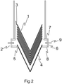
- a stack of nested cone sleeves 1 is introduced tip-downwards into the chamber 2 from above - i.e. via the upper circular opening 3.
- the lowermost cone sleeve 4 of the stack sits within the lower circular opening 5 and the cone sleeves above it in the stack 1 protrude from the top of the chamber 2.
- the chamber is defined by the wall 6, the upper surface 7 and the lower surface 8.
- the nested stack of cone sleeves 1 sits within the chamber 2 such that the lower circular opening 5 is blocked by the lowermost sleeve 4 and the upper rim of this sleeve 4 is located within the chamber 2.
- the sleeve or sleeves immediately above the lowermost sleeve are also located inside the chamber while the remainder of the stack protrudes from the top of the chamber.
- the upper opening 3 is therefore partially blocked by the cones in the stack.
- the chamber 2 is effectively sealed at the bottom 5 and the upper opening 3 is almost completely occluded by the other cone sleeves.
- pressurised gas is introduced into the chamber 2 via the inlets 9 to create an elevated pressure within the chamber.
- This pressure elevation occurs because the pressurised air enters the chamber 2 through the inlets 9 at a rate greater than the rate that the air can escape via the upper circular opening 3.
- a pressurised environment is therefore created within chamber 2.
- the pressure in the chamber is at least 100kPa, more preferably at least 110kPa, more preferably still at least 120kPa, yet more preferably at least 130kPa, even more preferably at least 140kPa, most preferably at least 150kPa.
- the pressure in the chamber is at most 200kPa, more preferably at most 190kPa, more preferably still at most 180kPa, yet more preferably at most 170kPa, most preferably at most 160kPa.
- the apparatus and process of the invention are actually capable of causing the rest of the stack to float above the lowermost cone as shown in Figure 2 .
- the inlets create an air blade that actually interacts with the cone sleeves.
- the inlets are configured to direct air downwards into the chamber and in this configuration not only does the air infiltrate between the cone sleeves but also serves to force the lowermost cone downwards as the air pressure within the chamber forces the rest of the stack upwards.
Landscapes
- Life Sciences & Earth Sciences (AREA)
- Chemical & Material Sciences (AREA)
- Engineering & Computer Science (AREA)
- Food Science & Technology (AREA)
- Polymers & Plastics (AREA)
- Stackable Containers (AREA)
Claims (13)
- Appareil pour séparer une douille de cône (4) d'un empilement de douilles de cônes emboîtées (1) l'appareil comprenant une chambre (2) présentant une surface supérieure (7) et une inférieure (8) connectées par une paroi ou des parois (6), la surface supérieure (7) présentant une ouverture circulaire supérieure (3) et la surface inférieure (8) présentant une ouverture circulaire inférieure (5)
dans lequel- l'ouverture circulaire supérieure (3) présente une circonférence de 100-135 % de la circonférence maximale de la douille de cône (4),- l'ouverture circulaire inférieure (5) présente une circonférence de 95-99,5 % de la circonférence maximale de la douille de cône (4), et- la chambre (2) présente des entrées (9) pouvant être connectées à une alimentation en gaz pressurisé,caractérisé en ce que les entrées (9) sont configurées pour diriger de l'air horizontalement ou vers le bas dans la chambre (2). - Appareil selon la revendication 1, dans lequel l'ouverture circulaire supérieure (3) présente une circonférence d'au moins 101 % de la circonférence maximale de la douille de cône (4).
- Appareil selon la revendication ou revendication 2, dans lequel l'ouverture circulaire supérieure (3) présente une circonférence d'au plus 130 % de la circonférence maximale de la douille de cône (4).
- Appareil selon l'une quelconque des revendications 1 à 3, dans lequel l'ouverture circulaire inférieure (5) présente une circonférence d'au moins 95,5 % de la circonférence maximale de la douille de cône (4).
- Appareil selon l'une quelconque des revendications 1 à 4, dans lequel l'ouverture circulaire inférieure (5) présente une circonférence d'au plus 99,25 % de la circonférence maximale de la douille de cône (4).
- Appareil selon l'une quelconque des revendications 1 à 5, dans lequel la distance entre la surface supérieure (7) et la surface inférieure (8) est d'au moins 5 mm.
- Appareil selon l'une quelconque des revendications 1 à 6, dans lequel la distance entre la surface supérieure (7) et la surface inférieure (8) comme mesurée à l'intérieur de la chambre est d'au plus 100 mm.
- Appareil selon l'une quelconque des revendications 1 à 7, dans lequel l'appareil comprend un support d'empilement de douilles de cônes.
- Appareil selon la revendication 8, dans lequel le support d'empilement comprend un empilement de douilles emboîtées présentant des extrémités arrondies.
- Procédé qui utilise un appareil pour séparer une douille de cône (4) d'un empilement de douilles de cônes emboîtées (1) l'appareil comprenant une chambre (2) présentant une surface supérieure (7) et une inférieure (8) connectées par une paroi ou des parois (6), la surface supérieure (7) présentant une ouverture circulaire supérieure (3) et la surface inférieure (8) présentant une ouverture circulaire inférieure (5)
dans lequel- l'ouverture circulaire supérieure (3) présente une circonférence de 100-135 % de la circonférence maximale de la douille de cône (4) ;- l'ouverture circulaire inférieure (5) présente une circonférence de 95-99,5 % de la circonférence maximale de la douille de cône (4) ; et- la chambre (2) présente des entrées (9) pouvant être connectées à une alimentation en gaz pressurisé ;le procédé comprenant les étapes consistant à :a) fournir un empilement de douilles de cônes emboîtées (1) ;b) disposer l'extrémité la plus basse de l'empilement dans la chambre (2) à partir du dessus de la chambre (2) ; etc) laisser la douille de cône la plus basse (4) s'assoir à l'intérieur de l'ouverture circulaire inférieure (5) et laisser les douilles de cônes au-dessus de la douille de cône la plus basse (4) faire saillie à partir du haut de la chambre (2)caractérisé en ce que du gaz pressurisé est introduit dans la chambre via les entrées (9) pour créer une pression élevée à l'intérieur de la chambre (2). - Procédé selon la revendication 10, dans lequel l'appareil comprend de plus des entrées (9) qui sont configurées pour diriger de l'air horizontalement ou vers le bas dans la chambre.
- Procédé selon la revendication 11, dans lequel la pression élevée dans la chambre (2) est d'au moins 100 kPa.
- Procédé selon la revendication 11 ou revendication 12, dans lequel la pression élevée dans la chambre (2) est d'au plus 200 kPa.
Applications Claiming Priority (2)
| Application Number | Priority Date | Filing Date | Title |
|---|---|---|---|
| EP2015181519 | 2015-08-19 | ||
| PCT/EP2016/067658 WO2017029075A1 (fr) | 2015-08-19 | 2016-07-25 | Appareil et procédé de manipulation d'emballages alimentaires |
Publications (2)
| Publication Number | Publication Date |
|---|---|
| EP3337740A1 EP3337740A1 (fr) | 2018-06-27 |
| EP3337740B1 true EP3337740B1 (fr) | 2022-03-23 |
Family
ID=62164621
Family Applications (1)
| Application Number | Title | Priority Date | Filing Date |
|---|---|---|---|
| EP16742308.6A Not-in-force EP3337740B1 (fr) | 2015-08-19 | 2016-07-25 | Appareil et procédé de manipulation de cones d'emballage |
Country Status (1)
| Country | Link |
|---|---|
| EP (1) | EP3337740B1 (fr) |
Citations (1)
| Publication number | Priority date | Publication date | Assignee | Title |
|---|---|---|---|---|
| GB1586858A (en) * | 1976-06-07 | 1981-03-25 | Unilever Ltd | Device for treating packaging components |
-
2016
- 2016-07-25 EP EP16742308.6A patent/EP3337740B1/fr not_active Not-in-force
Patent Citations (1)
| Publication number | Priority date | Publication date | Assignee | Title |
|---|---|---|---|---|
| GB1586858A (en) * | 1976-06-07 | 1981-03-25 | Unilever Ltd | Device for treating packaging components |
Also Published As
| Publication number | Publication date |
|---|---|
| EP3337740A1 (fr) | 2018-06-27 |
Similar Documents
| Publication | Publication Date | Title |
|---|---|---|
| AU2019204950B2 (en) | Apparatus and process for handling food packaging | |
| CA2875772C (fr) | Procede de manchonnage de recipient et systeme de fixation d'un manchon autour d'un recipient | |
| US6623236B1 (en) | Vacuum apparatus and method for denesting objects | |
| JP5266465B2 (ja) | コンタクトレンズの移送用プローブ及び移送方法 | |
| JP2019043652A (ja) | 三角サンドイッチ用包装機 | |
| KR20170142188A (ko) | 파우치들을 이송하기 위한 시스템 및 방법 | |
| US7036682B2 (en) | Destacking device for ice-cream cones | |
| EP3337740A1 (fr) | Appareil et procédé de manipulation d'emballages alimentaires | |
| US12286313B2 (en) | Transfer apparatus and process | |
| WO2006097399A1 (fr) | Appareil de distribution de capsules | |
| CN100564162C (zh) | 用于包装刚性的、一端敞开的容器的设备 | |
| SE537666C2 (sv) | Införsel av munstycke i spritspåse | |
| EP2676885B1 (fr) | Dispositif de remplissage de contenants avec des articles en forme de tige | |
| JP2004331125A (ja) | 飲料用被抽出材料の抽出バッグへの包装方法 | |
| CN108349671B (zh) | 用于使容纳多个坯件的料盒中的坯件对齐的装置和方法以及用于从容纳多个坯件的料盒中取出坯件的设备和方法 | |
| US2997832A (en) | Manually-operable capper for cottage cheese cartons and the like | |
| JP2013028355A (ja) | 被包装物充填方法及び装置 | |
| EP0925721A2 (fr) | Procédé de manipulation d'articles de crème glacée par exemple des cornets et organe de préhension à cet effet | |
| TWM536223U (zh) | 取瓶機 | |
| JPH0637926Y2 (ja) | コーンスリーブ供給装置 | |
| TWI423916B (zh) | Tissue paper dispensing mechanism | |
| WO2019087117A1 (fr) | Appareil servant à ouvrir un emballage de matériau en poudre | |
| EP3934987A1 (fr) | Procédé et dispositif de dépose de fruits ou légumes sur des plateaux alvéolés courbés | |
| JP2019043655A (ja) | 三角サンドイッチ用包装体給袋装置 |
Legal Events
| Date | Code | Title | Description |
|---|---|---|---|
| STAA | Information on the status of an ep patent application or granted ep patent |
Free format text: STATUS: THE INTERNATIONAL PUBLICATION HAS BEEN MADE |
|
| PUAI | Public reference made under article 153(3) epc to a published international application that has entered the european phase |
Free format text: ORIGINAL CODE: 0009012 |
|
| STAA | Information on the status of an ep patent application or granted ep patent |
Free format text: STATUS: REQUEST FOR EXAMINATION WAS MADE |
|
| STAA | Information on the status of an ep patent application or granted ep patent |
Free format text: STATUS: EXAMINATION IS IN PROGRESS |
|
| 17P | Request for examination filed |
Effective date: 20180109 |
|
| AK | Designated contracting states |
Kind code of ref document: A1 Designated state(s): AL AT BE BG CH CY CZ DE DK EE ES FI FR GB GR HR HU IE IS IT LI LT LU LV MC MK MT NL NO PL PT RO RS SE SI SK SM TR |
|
| AX | Request for extension of the european patent |
Extension state: BA ME |
|
| 17Q | First examination report despatched |
Effective date: 20180618 |
|
| DAV | Request for validation of the european patent (deleted) | ||
| DAX | Request for extension of the european patent (deleted) | ||
| RAP1 | Party data changed (applicant data changed or rights of an application transferred) |
Owner name: UNILEVER PLC Owner name: UNILEVER IP HOLDINGS B.V. |
|
| RAP1 | Party data changed (applicant data changed or rights of an application transferred) |
Owner name: UNILEVER IP HOLDINGS B.V. |
|
| RAP1 | Party data changed (applicant data changed or rights of an application transferred) |
Owner name: UNILEVER IP HOLDINGS B.V. |
|
| GRAP | Despatch of communication of intention to grant a patent |
Free format text: ORIGINAL CODE: EPIDOSNIGR1 |
|
| STAA | Information on the status of an ep patent application or granted ep patent |
Free format text: STATUS: GRANT OF PATENT IS INTENDED |
|
| INTG | Intention to grant announced |
Effective date: 20210623 |
|
| GRAJ | Information related to disapproval of communication of intention to grant by the applicant or resumption of examination proceedings by the epo deleted |
Free format text: ORIGINAL CODE: EPIDOSDIGR1 |
|
| STAA | Information on the status of an ep patent application or granted ep patent |
Free format text: STATUS: EXAMINATION IS IN PROGRESS |
|
| INTC | Intention to grant announced (deleted) | ||
| GRAP | Despatch of communication of intention to grant a patent |
Free format text: ORIGINAL CODE: EPIDOSNIGR1 |
|
| STAA | Information on the status of an ep patent application or granted ep patent |
Free format text: STATUS: GRANT OF PATENT IS INTENDED |
|
| GRAJ | Information related to disapproval of communication of intention to grant by the applicant or resumption of examination proceedings by the epo deleted |
Free format text: ORIGINAL CODE: EPIDOSDIGR1 |
|
| GRAP | Despatch of communication of intention to grant a patent |
Free format text: ORIGINAL CODE: EPIDOSNIGR1 |
|
| INTG | Intention to grant announced |
Effective date: 20211011 |
|
| INTG | Intention to grant announced |
Effective date: 20211027 |
|
| GRAS | Grant fee paid |
Free format text: ORIGINAL CODE: EPIDOSNIGR3 |
|
| GRAA | (expected) grant |
Free format text: ORIGINAL CODE: 0009210 |
|
| STAA | Information on the status of an ep patent application or granted ep patent |
Free format text: STATUS: THE PATENT HAS BEEN GRANTED |
|
| AK | Designated contracting states |
Kind code of ref document: B1 Designated state(s): AL AT BE BG CH CY CZ DE DK EE ES FI FR GB GR HR HU IE IS IT LI LT LU LV MC MK MT NL NO PL PT RO RS SE SI SK SM TR |
|
| REG | Reference to a national code |
Ref country code: GB Ref legal event code: FG4D |
|
| REG | Reference to a national code |
Ref country code: CH Ref legal event code: EP |
|
| REG | Reference to a national code |
Ref country code: IE Ref legal event code: FG4D |
|
| REG | Reference to a national code |
Ref country code: DE Ref legal event code: R096 Ref document number: 602016070270 Country of ref document: DE |
|
| REG | Reference to a national code |
Ref country code: AT Ref legal event code: REF Ref document number: 1477309 Country of ref document: AT Kind code of ref document: T Effective date: 20220415 |
|
| REG | Reference to a national code |
Ref country code: LT Ref legal event code: MG9D |
|
| REG | Reference to a national code |
Ref country code: NL Ref legal event code: MP Effective date: 20220323 |
|
| PG25 | Lapsed in a contracting state [announced via postgrant information from national office to epo] |
Ref country code: SE Free format text: LAPSE BECAUSE OF FAILURE TO SUBMIT A TRANSLATION OF THE DESCRIPTION OR TO PAY THE FEE WITHIN THE PRESCRIBED TIME-LIMIT Effective date: 20220323 Ref country code: RS Free format text: LAPSE BECAUSE OF FAILURE TO SUBMIT A TRANSLATION OF THE DESCRIPTION OR TO PAY THE FEE WITHIN THE PRESCRIBED TIME-LIMIT Effective date: 20220323 Ref country code: NO Free format text: LAPSE BECAUSE OF FAILURE TO SUBMIT A TRANSLATION OF THE DESCRIPTION OR TO PAY THE FEE WITHIN THE PRESCRIBED TIME-LIMIT Effective date: 20220623 Ref country code: LT Free format text: LAPSE BECAUSE OF FAILURE TO SUBMIT A TRANSLATION OF THE DESCRIPTION OR TO PAY THE FEE WITHIN THE PRESCRIBED TIME-LIMIT Effective date: 20220323 Ref country code: HR Free format text: LAPSE BECAUSE OF FAILURE TO SUBMIT A TRANSLATION OF THE DESCRIPTION OR TO PAY THE FEE WITHIN THE PRESCRIBED TIME-LIMIT Effective date: 20220323 Ref country code: BG Free format text: LAPSE BECAUSE OF FAILURE TO SUBMIT A TRANSLATION OF THE DESCRIPTION OR TO PAY THE FEE WITHIN THE PRESCRIBED TIME-LIMIT Effective date: 20220623 |
|
| REG | Reference to a national code |
Ref country code: AT Ref legal event code: MK05 Ref document number: 1477309 Country of ref document: AT Kind code of ref document: T Effective date: 20220323 |
|
| PG25 | Lapsed in a contracting state [announced via postgrant information from national office to epo] |
Ref country code: LV Free format text: LAPSE BECAUSE OF FAILURE TO SUBMIT A TRANSLATION OF THE DESCRIPTION OR TO PAY THE FEE WITHIN THE PRESCRIBED TIME-LIMIT Effective date: 20220323 Ref country code: GR Free format text: LAPSE BECAUSE OF FAILURE TO SUBMIT A TRANSLATION OF THE DESCRIPTION OR TO PAY THE FEE WITHIN THE PRESCRIBED TIME-LIMIT Effective date: 20220624 Ref country code: FI Free format text: LAPSE BECAUSE OF FAILURE TO SUBMIT A TRANSLATION OF THE DESCRIPTION OR TO PAY THE FEE WITHIN THE PRESCRIBED TIME-LIMIT Effective date: 20220323 |
|
| PG25 | Lapsed in a contracting state [announced via postgrant information from national office to epo] |
Ref country code: NL Free format text: LAPSE BECAUSE OF FAILURE TO SUBMIT A TRANSLATION OF THE DESCRIPTION OR TO PAY THE FEE WITHIN THE PRESCRIBED TIME-LIMIT Effective date: 20220323 |
|
| PG25 | Lapsed in a contracting state [announced via postgrant information from national office to epo] |
Ref country code: SM Free format text: LAPSE BECAUSE OF FAILURE TO SUBMIT A TRANSLATION OF THE DESCRIPTION OR TO PAY THE FEE WITHIN THE PRESCRIBED TIME-LIMIT Effective date: 20220323 Ref country code: SK Free format text: LAPSE BECAUSE OF FAILURE TO SUBMIT A TRANSLATION OF THE DESCRIPTION OR TO PAY THE FEE WITHIN THE PRESCRIBED TIME-LIMIT Effective date: 20220323 Ref country code: RO Free format text: LAPSE BECAUSE OF FAILURE TO SUBMIT A TRANSLATION OF THE DESCRIPTION OR TO PAY THE FEE WITHIN THE PRESCRIBED TIME-LIMIT Effective date: 20220323 Ref country code: PT Free format text: LAPSE BECAUSE OF FAILURE TO SUBMIT A TRANSLATION OF THE DESCRIPTION OR TO PAY THE FEE WITHIN THE PRESCRIBED TIME-LIMIT Effective date: 20220725 Ref country code: ES Free format text: LAPSE BECAUSE OF FAILURE TO SUBMIT A TRANSLATION OF THE DESCRIPTION OR TO PAY THE FEE WITHIN THE PRESCRIBED TIME-LIMIT Effective date: 20220323 Ref country code: EE Free format text: LAPSE BECAUSE OF FAILURE TO SUBMIT A TRANSLATION OF THE DESCRIPTION OR TO PAY THE FEE WITHIN THE PRESCRIBED TIME-LIMIT Effective date: 20220323 Ref country code: CZ Free format text: LAPSE BECAUSE OF FAILURE TO SUBMIT A TRANSLATION OF THE DESCRIPTION OR TO PAY THE FEE WITHIN THE PRESCRIBED TIME-LIMIT Effective date: 20220323 Ref country code: AT Free format text: LAPSE BECAUSE OF FAILURE TO SUBMIT A TRANSLATION OF THE DESCRIPTION OR TO PAY THE FEE WITHIN THE PRESCRIBED TIME-LIMIT Effective date: 20220323 |
|
| PG25 | Lapsed in a contracting state [announced via postgrant information from national office to epo] |
Ref country code: PL Free format text: LAPSE BECAUSE OF FAILURE TO SUBMIT A TRANSLATION OF THE DESCRIPTION OR TO PAY THE FEE WITHIN THE PRESCRIBED TIME-LIMIT Effective date: 20220323 Ref country code: IS Free format text: LAPSE BECAUSE OF FAILURE TO SUBMIT A TRANSLATION OF THE DESCRIPTION OR TO PAY THE FEE WITHIN THE PRESCRIBED TIME-LIMIT Effective date: 20220723 Ref country code: AL Free format text: LAPSE BECAUSE OF FAILURE TO SUBMIT A TRANSLATION OF THE DESCRIPTION OR TO PAY THE FEE WITHIN THE PRESCRIBED TIME-LIMIT Effective date: 20220323 |
|
| REG | Reference to a national code |
Ref country code: DE Ref legal event code: R097 Ref document number: 602016070270 Country of ref document: DE |
|
| PLBE | No opposition filed within time limit |
Free format text: ORIGINAL CODE: 0009261 |
|
| STAA | Information on the status of an ep patent application or granted ep patent |
Free format text: STATUS: NO OPPOSITION FILED WITHIN TIME LIMIT |
|
| PG25 | Lapsed in a contracting state [announced via postgrant information from national office to epo] |
Ref country code: DK Free format text: LAPSE BECAUSE OF FAILURE TO SUBMIT A TRANSLATION OF THE DESCRIPTION OR TO PAY THE FEE WITHIN THE PRESCRIBED TIME-LIMIT Effective date: 20220323 |
|
| REG | Reference to a national code |
Ref country code: DE Ref legal event code: R119 Ref document number: 602016070270 Country of ref document: DE |
|
| PG25 | Lapsed in a contracting state [announced via postgrant information from national office to epo] |
Ref country code: MC Free format text: LAPSE BECAUSE OF FAILURE TO SUBMIT A TRANSLATION OF THE DESCRIPTION OR TO PAY THE FEE WITHIN THE PRESCRIBED TIME-LIMIT Effective date: 20220323 |
|
| REG | Reference to a national code |
Ref country code: CH Ref legal event code: PL |
|
| 26N | No opposition filed |
Effective date: 20230102 |
|
| GBPC | Gb: european patent ceased through non-payment of renewal fee |
Effective date: 20220725 |
|
| REG | Reference to a national code |
Ref country code: BE Ref legal event code: MM Effective date: 20220731 |
|
| PG25 | Lapsed in a contracting state [announced via postgrant information from national office to epo] |
Ref country code: LU Free format text: LAPSE BECAUSE OF NON-PAYMENT OF DUE FEES Effective date: 20220725 Ref country code: LI Free format text: LAPSE BECAUSE OF NON-PAYMENT OF DUE FEES Effective date: 20220731 Ref country code: FR Free format text: LAPSE BECAUSE OF NON-PAYMENT OF DUE FEES Effective date: 20220731 Ref country code: CH Free format text: LAPSE BECAUSE OF NON-PAYMENT OF DUE FEES Effective date: 20220731 |
|
| PG25 | Lapsed in a contracting state [announced via postgrant information from national office to epo] |
Ref country code: SI Free format text: LAPSE BECAUSE OF FAILURE TO SUBMIT A TRANSLATION OF THE DESCRIPTION OR TO PAY THE FEE WITHIN THE PRESCRIBED TIME-LIMIT Effective date: 20220323 Ref country code: GB Free format text: LAPSE BECAUSE OF NON-PAYMENT OF DUE FEES Effective date: 20220725 Ref country code: DE Free format text: LAPSE BECAUSE OF NON-PAYMENT OF DUE FEES Effective date: 20230201 Ref country code: BE Free format text: LAPSE BECAUSE OF NON-PAYMENT OF DUE FEES Effective date: 20220731 |
|
| PG25 | Lapsed in a contracting state [announced via postgrant information from national office to epo] |
Ref country code: IT Free format text: LAPSE BECAUSE OF NON-PAYMENT OF DUE FEES Effective date: 20220725 Ref country code: IE Free format text: LAPSE BECAUSE OF NON-PAYMENT OF DUE FEES Effective date: 20220725 |
|
| PG25 | Lapsed in a contracting state [announced via postgrant information from national office to epo] |
Ref country code: HU Free format text: LAPSE BECAUSE OF FAILURE TO SUBMIT A TRANSLATION OF THE DESCRIPTION OR TO PAY THE FEE WITHIN THE PRESCRIBED TIME-LIMIT; INVALID AB INITIO Effective date: 20160725 |
|
| PG25 | Lapsed in a contracting state [announced via postgrant information from national office to epo] |
Ref country code: MK Free format text: LAPSE BECAUSE OF FAILURE TO SUBMIT A TRANSLATION OF THE DESCRIPTION OR TO PAY THE FEE WITHIN THE PRESCRIBED TIME-LIMIT Effective date: 20220323 Ref country code: CY Free format text: LAPSE BECAUSE OF FAILURE TO SUBMIT A TRANSLATION OF THE DESCRIPTION OR TO PAY THE FEE WITHIN THE PRESCRIBED TIME-LIMIT Effective date: 20220323 |
|
| PG25 | Lapsed in a contracting state [announced via postgrant information from national office to epo] |
Ref country code: MT Free format text: LAPSE BECAUSE OF FAILURE TO SUBMIT A TRANSLATION OF THE DESCRIPTION OR TO PAY THE FEE WITHIN THE PRESCRIBED TIME-LIMIT Effective date: 20220323 |
|
| PG25 | Lapsed in a contracting state [announced via postgrant information from national office to epo] |
Ref country code: TR Free format text: LAPSE BECAUSE OF NON-PAYMENT OF DUE FEES Effective date: 20220725 |