EP3337751B1 - Procédé pour la surveillance de sites de construction, machine de construction et système de surveillance du site de construction - Google Patents
Procédé pour la surveillance de sites de construction, machine de construction et système de surveillance du site de construction Download PDFInfo
- Publication number
- EP3337751B1 EP3337751B1 EP16760384.4A EP16760384A EP3337751B1 EP 3337751 B1 EP3337751 B1 EP 3337751B1 EP 16760384 A EP16760384 A EP 16760384A EP 3337751 B1 EP3337751 B1 EP 3337751B1
- Authority
- EP
- European Patent Office
- Prior art keywords
- monitoring
- construction site
- processing unit
- machine
- accordance
- Prior art date
- Legal status (The legal status is an assumption and is not a legal conclusion. Google has not performed a legal analysis and makes no representation as to the accuracy of the status listed.)
- Active
Links
Images

Classifications
-
- B—PERFORMING OPERATIONS; TRANSPORTING
- B66—HOISTING; LIFTING; HAULING
- B66C—CRANES; LOAD-ENGAGING ELEMENTS OR DEVICES FOR CRANES, CAPSTANS, WINCHES, OR TACKLES
- B66C13/00—Other constructional features or details
- B66C13/16—Applications of indicating, registering, or weighing devices
-
- B—PERFORMING OPERATIONS; TRANSPORTING
- B66—HOISTING; LIFTING; HAULING
- B66C—CRANES; LOAD-ENGAGING ELEMENTS OR DEVICES FOR CRANES, CAPSTANS, WINCHES, OR TACKLES
- B66C13/00—Other constructional features or details
- B66C13/18—Control systems or devices
- B66C13/40—Applications of devices for transmitting control pulses; Applications of remote control devices
-
- B—PERFORMING OPERATIONS; TRANSPORTING
- B66—HOISTING; LIFTING; HAULING
- B66C—CRANES; LOAD-ENGAGING ELEMENTS OR DEVICES FOR CRANES, CAPSTANS, WINCHES, OR TACKLES
- B66C15/00—Safety gear
-
- B—PERFORMING OPERATIONS; TRANSPORTING
- B66—HOISTING; LIFTING; HAULING
- B66C—CRANES; LOAD-ENGAGING ELEMENTS OR DEVICES FOR CRANES, CAPSTANS, WINCHES, OR TACKLES
- B66C15/00—Safety gear
- B66C15/04—Safety gear for preventing collisions, e.g. between cranes or trolleys operating on the same track
- B66C15/045—Safety gear for preventing collisions, e.g. between cranes or trolleys operating on the same track electrical
-
- B—PERFORMING OPERATIONS; TRANSPORTING
- B66—HOISTING; LIFTING; HAULING
- B66C—CRANES; LOAD-ENGAGING ELEMENTS OR DEVICES FOR CRANES, CAPSTANS, WINCHES, OR TACKLES
- B66C15/00—Safety gear
- B66C15/06—Arrangements or use of warning devices
- B66C15/065—Arrangements or use of warning devices electrical
-
- G—PHYSICS
- G01—MEASURING; TESTING
- G01S—RADIO DIRECTION-FINDING; RADIO NAVIGATION; DETERMINING DISTANCE OR VELOCITY BY USE OF RADIO WAVES; LOCATING OR PRESENCE-DETECTING BY USE OF THE REFLECTION OR RERADIATION OF RADIO WAVES; ANALOGOUS ARRANGEMENTS USING OTHER WAVES
- G01S13/00—Systems using the reflection or reradiation of radio waves, e.g. radar systems; Analogous systems using reflection or reradiation of waves whose nature or wavelength is irrelevant or unspecified
- G01S13/02—Systems using reflection of radio waves, e.g. primary radar systems; Analogous systems
- G01S13/06—Systems determining position data of a target
- G01S13/42—Simultaneous measurement of distance and other co-ordinates
-
- G—PHYSICS
- G01—MEASURING; TESTING
- G01S—RADIO DIRECTION-FINDING; RADIO NAVIGATION; DETERMINING DISTANCE OR VELOCITY BY USE OF RADIO WAVES; LOCATING OR PRESENCE-DETECTING BY USE OF THE REFLECTION OR RERADIATION OF RADIO WAVES; ANALOGOUS ARRANGEMENTS USING OTHER WAVES
- G01S13/00—Systems using the reflection or reradiation of radio waves, e.g. radar systems; Analogous systems using reflection or reradiation of waves whose nature or wavelength is irrelevant or unspecified
- G01S13/86—Combinations of radar systems with non-radar systems, e.g. sonar, direction finder
- G01S13/865—Combination of radar systems with lidar systems
-
- G—PHYSICS
- G01—MEASURING; TESTING
- G01S—RADIO DIRECTION-FINDING; RADIO NAVIGATION; DETERMINING DISTANCE OR VELOCITY BY USE OF RADIO WAVES; LOCATING OR PRESENCE-DETECTING BY USE OF THE REFLECTION OR RERADIATION OF RADIO WAVES; ANALOGOUS ARRANGEMENTS USING OTHER WAVES
- G01S13/00—Systems using the reflection or reradiation of radio waves, e.g. radar systems; Analogous systems using reflection or reradiation of waves whose nature or wavelength is irrelevant or unspecified
- G01S13/88—Radar or analogous systems specially adapted for specific applications
- G01S13/93—Radar or analogous systems specially adapted for specific applications for anti-collision purposes
-
- G—PHYSICS
- G01—MEASURING; TESTING
- G01S—RADIO DIRECTION-FINDING; RADIO NAVIGATION; DETERMINING DISTANCE OR VELOCITY BY USE OF RADIO WAVES; LOCATING OR PRESENCE-DETECTING BY USE OF THE REFLECTION OR RERADIATION OF RADIO WAVES; ANALOGOUS ARRANGEMENTS USING OTHER WAVES
- G01S17/00—Systems using the reflection or reradiation of electromagnetic waves other than radio waves, e.g. lidar systems
- G01S17/02—Systems using the reflection of electromagnetic waves other than radio waves
- G01S17/06—Systems determining position data of a target
- G01S17/42—Simultaneous measurement of distance and other co-ordinates
-
- G—PHYSICS
- G01—MEASURING; TESTING
- G01S—RADIO DIRECTION-FINDING; RADIO NAVIGATION; DETERMINING DISTANCE OR VELOCITY BY USE OF RADIO WAVES; LOCATING OR PRESENCE-DETECTING BY USE OF THE REFLECTION OR RERADIATION OF RADIO WAVES; ANALOGOUS ARRANGEMENTS USING OTHER WAVES
- G01S17/00—Systems using the reflection or reradiation of electromagnetic waves other than radio waves, e.g. lidar systems
- G01S17/88—Lidar systems specially adapted for specific applications
- G01S17/89—Lidar systems specially adapted for specific applications for mapping or imaging
-
- G—PHYSICS
- G01—MEASURING; TESTING
- G01S—RADIO DIRECTION-FINDING; RADIO NAVIGATION; DETERMINING DISTANCE OR VELOCITY BY USE OF RADIO WAVES; LOCATING OR PRESENCE-DETECTING BY USE OF THE REFLECTION OR RERADIATION OF RADIO WAVES; ANALOGOUS ARRANGEMENTS USING OTHER WAVES
- G01S17/00—Systems using the reflection or reradiation of electromagnetic waves other than radio waves, e.g. lidar systems
- G01S17/88—Lidar systems specially adapted for specific applications
- G01S17/93—Lidar systems specially adapted for specific applications for anti-collision purposes
-
- B—PERFORMING OPERATIONS; TRANSPORTING
- B66—HOISTING; LIFTING; HAULING
- B66C—CRANES; LOAD-ENGAGING ELEMENTS OR DEVICES FOR CRANES, CAPSTANS, WINCHES, OR TACKLES
- B66C15/00—Safety gear
- B66C15/06—Arrangements or use of warning devices
Definitions
- the invention relates to a method for real-time monitoring of the current status of a construction site with one or more work machines.
- the document DE112012000169T5 discloses a method for real-time monitoring of the current status of a construction site with one or more work machines, wherein a monitoring means installed on at least one work machine observes the work machine in real time and generates corresponding observation data, and the generated observation data are transmitted from the monitoring means to a computing unit for real-time evaluation of the current construction site status.
- the present invention therefore sets itself the task of finding a suitable solution for automated construction site monitoring.
- a method for real-time monitoring of the current status of a construction site with one or more work machines is proposed.
- a monitoring device installed on at least one work machine observes the environment of the work machine in real time and generates corresponding observation data for subsequent processing.
- This generated observation data is transmitted from the monitoring device to at least one computing unit for real-time evaluation of the current construction site status.
- the monitoring device(s) record any buildings in the vicinity of the work machine in real time.
- the recording and generation of the observation data can be done continuously or cyclically or manually at the user's request.
- the observation data generated can enable conclusions to be drawn about the progress on the construction site. By comparing it with a digitalized During site planning, the current construction progress is monitored and checked.
- the installed monitoring device can be, for example, a camera or a scanner device attached to a suitable work machine on the construction site. is installed. It is also conceivable to use transponder/transceiver technology for monitoring, whereby the work machine or its components and/or building components are equipped with corresponding transponder or transceiver modules. Suitable work machines are those that allow a high installation position so that the monitoring device has a good overview of at least part of the construction site. In this case, construction cranes are particularly suitable, ie tower cranes that allow the monitoring device to be installed at a high height, for example in the area of the tower top or on the boom system. The ability of the boom system to swivel at high heights leads to a large observation radius.
- the environment can be monitored without restricting construction site operations during the regular operation of the work machine.
- the monitoring device generates observation data that represents details of the environment of the work machine, for example one or more other work machines on the construction site and their movements, and/or building structures and their conditions and/or other objects on the construction site and people on the construction site.
- the transmission of the observation data to at least one computer unit allows the subsequent evaluation of the current construction site status. This step no longer has to be carried out manually using written documents, but can be carried out fully or at least partially automatically at the push of a button.
- the computer unit simply reproduces the recorded observation data, for example as image information, so that at least a remote inspection of the construction site status is possible by a responsible specialist.
- the observation data provides a two- or three-dimensional visual representation of the machine environment.
- a laser scanner with three-dimensional scanning of the construction site environment is used as a monitoring tool.
- radar and/or a transceiver-transponder solution such as RFID or RuBee, is also conceivable.
- the computing unit is either a central computing unit or is part of the machine control system of the observing work machine.
- the advantage of outsourcing the computing unit to a central computing unit is that it can be responsible for one or more work machines or monitoring devices on the construction site. It is conceivable that several work machines are equipped with corresponding monitoring devices so that the observation data generated by different work machines can be brought together in the central computing unit and evaluated together. This provides optimized coverage of the observable construction site area.
- the arrangement of monitoring devices on other objects, e.g. on building trades themselves, is also conceivable.
- the evaluation and presentation of the current construction site status can, for example, be carried out on user request or cyclically.
- the central processing unit carries out anti-collision monitoring of one or more work machines based on the observation data received.
- the observation data can be used to detect certain dangerous situations at an early stage, predict them if necessary, and send warnings to the respective machine controls if necessary. of the work machine.
- the central processing unit could intervene directly in the control of the respective work machines.
- the computing unit is part of the machine control system of the observing work machine, these observation data can be taken into account directly for controlling the machine actuators. This is particularly useful when implementing anti-collision monitoring.
- a distributed system consisting of a local machine control system and a central computing unit can also be used to implement the computing unit.
- Controlling one or more work machines via the processing unit can not only be useful for anti-collision purposes, but can also enable fully automated handling of the construction site. It is conceivable, for example, that one or more work machines on the construction site can be remotely controlled fully automatically by the central processing unit, so that progress on the construction site can be planned, monitored and carried out automatically.
- the present object is also achieved by a work machine, in particular a crane, with at least one monitoring means for real-time monitoring of the work machine environment.
- a monitoring means for real-time monitoring of the work machine environment.
- communication means are available that enable the observation data generated by the monitoring means to be transmitted to a central processing unit and/or a local machine control system of the work machine.
- a work machine is suitable for implementing the method according to the invention.
- the advantages and properties of the method according to the invention therefore also apply to the work machine according to the invention without restriction.
- the monitoring device can comprise a laser scanner device, in particular a 3D laser scanner, or alternatively be another camera device for creating visual observation data.
- the scanning method used by the laser scanner unit can be based on "airborne laser scanning” or alternatively on “terrestrial laser scanning”.
- the laser scanner unit is preferably arranged at a high mounting point on the work machine. In the case of a crane, in this case it can be arranged in the area of the tower tip or the crane boom or on the trolley or the load hook.
- the monitoring device can be powered, for example, via the regular power supply of a trolley. It is of course conceivable to integrate a separate power supply or an energy supply from other consumers of the crane.
- the monitoring device can also have at least one radar module, which consists of a radar transmitter and radar receiver.
- the additional radar module also allows additional spatial information to be recorded; for example, a three-dimensional model of the environment can be displayed using distance measurements, particularly in conjunction with the data from the laser scanner.
- the monitoring device alternatively or additionally includes a transponder/transceiver solution.
- Work machines or their components as well as other construction site objects or building components can be equipped with corresponding transponders that can be detected by a receiver module of the monitoring device.
- These could be built into the existing monitoring devices in the same way as the laser scanners, or they could also be installed additionally.
- An RFID system could be used as a transponder/transceiver solution. Since RFID systems have the disadvantage of being severely limited in their reception capability by metals, the standardized LWID (Long Wave IDentfikation) technology, also known as RuBee technology, could be used as an alternative or in addition. known, which also enables 3D recording of work machines, especially cranes, components, or all building components that are equipped with such transceiver modules/units. The units used can record objects, save them, and incorporate them into the BIM data (3D building information) of the building planning.
- LWID Long Wave IDentfikation
- RuBee technology also known as RuBee technology
- RFID is often used in transponder technology, but this technology has serious disadvantages when used with metals.
- LWID Long Wave IDentfikation
- RuBee a new technology
- the invention also includes a system with at least one such work machine according to the present invention.
- the system is suitable for carrying out the method according to the invention, which is why the system is characterized by the same advantages and properties as the method or the work machine. A repeated description is therefore not considered necessary.
- the main idea behind the invention is to digitally simulate, pre-plan and monitor construction sites in the future and optionally operate them automatically.
- construction cranes in particular are to be remotely controlled in an automated or at least partially automated manner.
- facilities in the future that can record and communicate construction progress in three dimensions in real time. This is a basic requirement for the subsequent automation of construction site operations.
- a system is desired that can effectively prevent possible collisions between individual construction machines on the construction site and can even calculate them in advance.
- Construction cranes usually cover all areas of the construction site and can thus record information on the geometry and condition without obstruction.
- a laser scanner device is installed on a construction crane, which systematically scans the construction site even during regular construction site operations. This information is sent to the construction site operators. The operator thus receives an up-to-date picture of the construction status regularly or at the push of a button, without having to be on site.
- the laser scanner device is installed on the construction crane near the tower or on the boom system.
- the laser scanner device can be installed on the boom system or directly on the trolley or on the load hook.
- the power supply to the trolley or load hook can be used to supply the laser scanner unit with energy.
- the scanner module can also have a radar sensor and receiver to obtain additional spatial information and thereby avoid collisions if necessary.
- the crane's observation data is transmitted to a central processing unit, which evaluates the data received and uses it to monitor construction site operations.
- a central processing unit which evaluates the data received and uses it to monitor construction site operations.
- collision monitoring of the individual work machines can also be carried out, which works on the basis of the image material provided by the laser scanner device or radar system.
- the central processing unit communicates with the individual machine controls of the construction cranes.
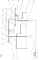
- the two Figures 1 , 2 outline a possible construction site scenario for the use of the system according to the invention.
- this comprises two construction site cranes 10, 11 that operate independently of one another and are each designed as tower cranes.
- a construction site monitoring system is set up that allows monitoring of the progress on the construction site, for example monitoring of the progress of the buildings 20, 21 shown as examples.
- both cranes are equipped with suitable monitoring devices 30, 31 in the form of three-dimensional laser scanners.
- a first sensor 30 is attached in the area of the load hook 12.
- the necessary power supply for the sensor 30 is provided via the power supply of the trolley 13.
- a lateral and downward detection of the sensor 30 is indicated, but the invention is not intended to be limited to a specific detection area or detection angle, although the construction site area below and next to the crane boom is usually of interest.
- a further sensor system 31 is mounted on both cranes 10, 11 in the area of the boom counterballast 15, which scans the environment behind the counterballast.
- the 3D laser scanner sensor system 31 is not necessarily limited to a specific detection range.
- Both laser scanner sensors 30, 31 move with the boom rotation movement so that a large area of the construction site can be scanned during crane operation.
- Figure 1 shows the working radii 40, 41 of the crane booms and illustrates the detectable area of the integrated sensors 30, 31. This allows a complete image of the construction site to be generated during the crane work with the appropriate crane movement. In combination with the boom height of the cranes 10, 11, the entire construction site can be recorded almost without gaps.
- the two 3D laser scanner sensors 30, 31 communicate with their respective crane control 16 of the two cranes 10, 11 and transmit their detection data to the respective control 16 continuously or on request.
- a central processing unit 40 is provided for central construction site monitoring, which is communicatively connected to the two crane controls 16 for exchanging the sensor signals of the sensors 30, 31.
- a direct connection of the processing unit 40 to the respective sensors 30, 31 is also conceivable.
- the communication between the central processing unit 40 and the cranes 10, 11 is bidirectional.
- the central processing unit 40 can determine the current status on the construction site based on the sensor signals.
- the sensors 30, 31 not only record the buildings 20, 21 and their construction progress, but it is also possible to use the sensors 30, 31 to monitor other work machines on the construction site and their movements. Based on this, collision monitoring can be implemented using the sensor data, which detects possible collisions between the cranes 10, 11 at an early stage and takes countermeasures if necessary.
- the central unit 40 directly influences the respective crane controls 16 and transmits control commands to the machines for remote control of the cranes 10, 11. If, for example, an impending collision between the two machines is detected, 10, 11 is detected by the computing unit 40, a corresponding stop signal is transmitted to one or both cranes 10, 11 and an immediate machine stop is initiated.
- the two crane controls 16 can also be coupled to one another for mutual information exchange.
- the evaluation of the sensor data received by the central processing unit 40 can be carried out either continuously or, if required, upon manual user request.
- the system according to the invention therefore creates possibilities for continuously monitoring the current status of the construction site electronically, even during operation. It is particularly advantageous that the monitoring does not have to take place on site, but can also be carried out by the processing unit 40 via remote access from any location, such as the construction manager's headquarters.
Landscapes
- Engineering & Computer Science (AREA)
- Radar, Positioning & Navigation (AREA)
- Remote Sensing (AREA)
- Physics & Mathematics (AREA)
- Computer Networks & Wireless Communication (AREA)
- General Physics & Mathematics (AREA)
- Mechanical Engineering (AREA)
- Electromagnetism (AREA)
- Automation & Control Theory (AREA)
- Optical Radar Systems And Details Thereof (AREA)
- Jib Cranes (AREA)
- Operation Control Of Excavators (AREA)
- Control And Safety Of Cranes (AREA)
Claims (9)
- Procédé de surveillance en temps réel de l'état actuel d'un chantier avec une ou plusieurs machines de travail (10, 11),un moyen de surveillance (30, 31) installé sur au moins une machine de travail (10, 11) observant en temps réel l'environnement de la machine de travail (10, 11) et générant des données d'observation correspondantes, etles données d'observation générées étant transmises par le moyen de surveillance (30, 31) à une unité de calcul (40) pour l'évaluation en temps réel de l'état actuel du chantier,le moyen de surveillance (30, 31) détectant et observant des bâtiments (20, 21) dans l'environnement de la machine,l'unité de calcul (40) évaluant, à l'aide des données d'observation collectées, un état d'avancement actuel de la construction des bâtiments (20, 21) conformément à un planning de construction, en comparant les données d'observation collectées à un planning de chantier numérisé, etles données d'observation comprenant une représentation imagée bidimensionnelle ou tridimensionnelle de l'environnement de la machine, les bâtiments détectés (20, 21) étant modélisés au moyen d'un logiciel de modélisation des informations du bâtiment (BIM).
- Procédé selon la revendication 1, caractérisé en ce que l'unité de calcul (40) est une unité de calcul centrale (40) qui reçoit des données d'observation d'une ou plusieurs machines de travail (10, 11) se trouvant sur le chantier, les évalue et, en option, représente l'état actuel du chantier, de préférence en réponse à une demande manuelle de l'utilisateur ou automatiquement à intervalles cycliques.
- Procédé selon l'une quelconque des revendications précédentes, caractérisé en ce que le moyen de surveillance (30, 31) détecte et observe en outre des objets de chantier, des personnes et/ou d'autres machines de travail (10, 11) dans l'environnement de la machine, et l'unité de calcul (40) effectue une surveillance anticollision entre une ou plusieurs machines de travail (10, 11) et des objets de chantier et/ou d'autres machines de travail (10, 11) stationnées sur le chantier à l'aide des données d'observation reçues.
- Procédé selon l'une quelconque des revendications précédentes, caractérisé en ce que l'unité de calcul (40) fait partie de la commande de machine de la machine de travail (10, 11) qui observe, les données d'observation amenées à la commande de machine étant prises en compte pour la commande des un ou plusieurs actionneurs de la machine.
- Procédé selon l'une quelconque des revendications précédentes, caractérisé en ce que l'unité de calcul (40) est une unité de calcul centrale (40) et les données d'observation de l'au moins une machine de travail (10, 11) servent à la commande à distance d'une ou plusieurs machines de travail (10, 11) sur le chantier.
- Système pour la mise en oeuvre du procédé selon l'une quelconque des revendications 1 à 5, comprenant une unité de calcul centrale (40) et au moins une machine de travail (10, 11), la machine de travail (10, 11) comprenant au moins un moyen de surveillance (30, 31) pour surveiller en temps réel l'environnement de la machine de travail ainsi qu'un moyen de communication pour transmettre les données d'observation générées à l'unité de calcul centrale (40).
- Système selon la revendication 6, dans lequel le moyen de surveillance (30, 31) comprend un dispositif de balayage laser, notamment un scanner laser 3D, et/ou une technologie d'émetteur-récepteur/transpondeur, comme de préférence RFID et/ou RuBee.
- Système selon l'une quelconque des revendications 6 ou 7, caractérisé en ce que le moyen de surveillance (30, 31) est agencé sur la flèche de la machine de travail (10, 11), l'alimentation en courant électrique du moyen de surveillance (30, 31) étant de préférence fournie par une alimentation en énergie existante de la flèche, par exemple l'amenée de courant électrique d'un chariot roulant.
- Système selon l'une quelconque des revendications 6 à 8, dans lequel le moyen de surveillance (30, 31) comprend en outre un module radar constitué d'un émetteur et d'un récepteur radar pour l'acquisition d'informations spatiales supplémentaires.
Applications Claiming Priority (2)
| Application Number | Priority Date | Filing Date | Title |
|---|---|---|---|
| DE102015010726.7A DE102015010726A1 (de) | 2015-08-17 | 2015-08-17 | Verfahren zur Baustellenüberwachung, Arbeitsmaschine und System zur Baustellenüberwachung |
| PCT/EP2016/001398 WO2017028951A1 (fr) | 2015-08-17 | 2016-08-16 | Procédé de surveillance d'un chantier, engin de travail et système de surveillance d'un chantier |
Publications (2)
| Publication Number | Publication Date |
|---|---|
| EP3337751A1 EP3337751A1 (fr) | 2018-06-27 |
| EP3337751B1 true EP3337751B1 (fr) | 2024-11-20 |
Family
ID=56855403
Family Applications (1)
| Application Number | Title | Priority Date | Filing Date |
|---|---|---|---|
| EP16760384.4A Active EP3337751B1 (fr) | 2015-08-17 | 2016-08-16 | Procédé pour la surveillance de sites de construction, machine de construction et système de surveillance du site de construction |
Country Status (6)
| Country | Link |
|---|---|
| US (2) | US10899585B2 (fr) |
| EP (1) | EP3337751B1 (fr) |
| CN (1) | CN108137294A (fr) |
| DE (1) | DE102015010726A1 (fr) |
| ES (1) | ES3010329T3 (fr) |
| WO (1) | WO2017028951A1 (fr) |
Families Citing this family (31)
| Publication number | Priority date | Publication date | Assignee | Title |
|---|---|---|---|---|
| EP3257805B1 (fr) * | 2016-06-13 | 2018-12-26 | Cargotec Patenter AB | Grue hydraulique |
| ES2899585T3 (es) | 2016-07-15 | 2022-03-14 | Fastbrick Ip Pty Ltd | Pluma para transporte de material |
| JP7061119B2 (ja) | 2016-07-15 | 2022-04-27 | ファストブリック・アイピー・プロプライエタリー・リミテッド | 車両に組み込まれた煉瓦/ブロック敷設機 |
| CN111095355B (zh) | 2017-07-05 | 2023-10-20 | 快砖知识产权私人有限公司 | 实时定位和定向跟踪器 |
| AU2018317941B2 (en) | 2017-08-17 | 2023-11-09 | Fastbrick Ip Pty Ltd | Laser tracker with improved roll angle measurement |
| US11958193B2 (en) | 2017-08-17 | 2024-04-16 | Fastbrick Ip Pty Ltd | Communication system for an interaction system |
| DE102017123391A1 (de) * | 2017-10-09 | 2019-04-11 | Liebherr-Werk Biberach Gmbh | Vorrichtung zum Steuern, Überwachen und Visualisieren von Baustellen |
| CN111212799B (zh) | 2017-10-11 | 2023-04-14 | 快砖知识产权私人有限公司 | 用于传送物体的机器以及与其一起使用的多隔间转盘 |
| DE102018100133A1 (de) * | 2018-01-04 | 2019-07-04 | Liebherr-Werk Biberach Gmbh | Kran mit Anti-Kollisions-Einrichtung sowie Verfahren zum Betreiben mehrerer solcher Krane |
| DE102018200221A1 (de) | 2018-01-09 | 2019-07-11 | Robert Bosch Gmbh | Verfahren zur Baustellenüberwachung |
| EP3533934B1 (fr) * | 2018-03-01 | 2020-07-15 | BAUER Spezialtiefbau GmbH | Procédé de construction |
| US10883256B2 (en) * | 2018-05-25 | 2021-01-05 | Deere & Company | Object responsive control system for a work machine |
| US12311546B2 (en) | 2018-07-16 | 2025-05-27 | Fastbrick Ip Pty Ltd | Active damping system |
| WO2020014737A1 (fr) | 2018-07-16 | 2020-01-23 | Fastbrick Ip Pty Ltd | Suivi de sauvegarde pour système d'interactions |
| CN109242372A (zh) * | 2018-11-23 | 2019-01-18 | 中如建工集团有限公司 | 建筑工程项目智能化施工方法 |
| CN109592586A (zh) * | 2018-12-18 | 2019-04-09 | 济南大学 | 一种判断两台塔吊协同作业起重臂碰撞的方法 |
| CN109884939A (zh) * | 2019-02-18 | 2019-06-14 | 上海添辉建筑工程有限公司 | 一种建筑工程环境监控装置 |
| CN109775588A (zh) * | 2019-02-28 | 2019-05-21 | 上海建工五建集团有限公司 | 一种塔吊防碰撞装置及施工方法 |
| US20220284366A1 (en) * | 2019-08-02 | 2022-09-08 | Global Engineers Technology Pte. Ltd. | Method and system for managing a crane and/or construction site |
| JP7415480B2 (ja) * | 2019-11-25 | 2024-01-17 | コベルコ建機株式会社 | 作業支援サーバおよび作業支援システム |
| CN111274635A (zh) * | 2020-01-19 | 2020-06-12 | 深圳云联万企科技有限公司 | 一种基于建筑信息模型的施工安全管理系统及方法 |
| CN115443363A (zh) | 2020-04-22 | 2022-12-06 | 快砖知识产权私人有限公司 | 块传送装置及用于与其一起使用的改进的夹紧组件 |
| AU2021304545B2 (en) | 2020-07-08 | 2025-12-04 | Fastbrick Ip Pty Ltd | Adhesive application system |
| CN111857070A (zh) * | 2020-07-09 | 2020-10-30 | 国网浙江省电力有限公司嘉兴供电公司 | 一种施工现场监测系统及监测方法 |
| CN112752380B (zh) * | 2020-12-31 | 2023-04-18 | 三一海洋重工有限公司 | 一种机械设备的照明控制方法、装置、介质及电子设备 |
| CN113911925A (zh) * | 2021-09-14 | 2022-01-11 | 杭州大杰智能传动科技有限公司 | 用于智能塔吊工作空间预警监测的系统及方法 |
| KR102845830B1 (ko) * | 2022-05-25 | 2025-08-14 | 주식회사 메타뷰 | 산업현장에서의 영상인식기반 가상물체 정합방법을 활용한 작업보조 시스템 |
| US20240168479A1 (en) * | 2022-11-21 | 2024-05-23 | Ford Global Technologies, Llc | Vehicular worksite monitoring and assistance |
| US12421695B2 (en) | 2023-08-23 | 2025-09-23 | Deere & Company | Scraper control method having variable operating modes corresponding to operator experience levels |
| CN118710472B (zh) * | 2024-07-30 | 2025-03-21 | 陕西中电数通科技有限公司 | 一种智慧工地安全监测管理系统及方法 |
| CN119612389B (zh) * | 2024-12-12 | 2025-11-04 | 广东达丰机械工程有限公司 | 一种塔机智能远程预警方法及系统 |
Citations (4)
| Publication number | Priority date | Publication date | Assignee | Title |
|---|---|---|---|---|
| US20080208415A1 (en) * | 2007-02-28 | 2008-08-28 | Caterpillar Inc. | Method of determining a machine operation using virtual imaging |
| DE112009001554T5 (de) * | 2008-06-27 | 2011-05-12 | Caterpillar Inc., Peoria | Vermeidungssystem für eine Baustelle |
| DE112009002054T5 (de) * | 2008-08-22 | 2011-07-14 | Caterpillar Trimble Control Technologies LLC, Ohio | Dreidimensionale Abtastvorrichtung, die eine dynamische Aktualisierung enthält |
| DE112012000169T5 (de) * | 2011-07-05 | 2013-07-18 | Trimble Navigation Limited | Kranmanöverunterstützung |
Family Cites Families (82)
| Publication number | Priority date | Publication date | Assignee | Title |
|---|---|---|---|---|
| JP3424834B2 (ja) * | 1997-02-20 | 2003-07-07 | 株式会社小松製作所 | 車両の監視装置 |
| JP3364419B2 (ja) * | 1997-10-29 | 2003-01-08 | 新キャタピラー三菱株式会社 | 遠隔無線操縦システム並びに遠隔操縦装置,移動式中継局及び無線移動式作業機械 |
| US6108949A (en) * | 1997-12-19 | 2000-08-29 | Carnegie Mellon University | Method and apparatus for determining an excavation strategy |
| US6446053B1 (en) * | 1999-08-06 | 2002-09-03 | Michael Elliott | Computer-implemented method and system for producing a proposal for a construction project |
| WO2001088827A1 (fr) * | 2000-05-15 | 2001-11-22 | Modular Mining Systems, Inc. | Systeme de permission destine a la commande de vehicules autonomes |
| US20040210370A1 (en) * | 2000-12-16 | 2004-10-21 | Gudat Adam J | Method and apparatus for displaying an excavation to plan |
| US7283975B2 (en) * | 2001-02-05 | 2007-10-16 | Broughton W Curtis | System and method for tracking and managing construction projects |
| JP4183114B2 (ja) * | 2002-09-04 | 2008-11-19 | 株式会社小松製作所 | 鉱山運搬管理システム及び方法 |
| SE526913C2 (sv) * | 2003-01-02 | 2005-11-15 | Arnex Navigation Systems Ab | Förfarande i form av intelligenta funktioner för fordon och automatiska lastmaskiner gällande kartläggning av terräng och materialvolymer, hinderdetektering och styrning av fordon och arbetsredskap |
| JP4233932B2 (ja) * | 2003-06-19 | 2009-03-04 | 日立建機株式会社 | 作業機械の作業支援・管理システム |
| JP4218449B2 (ja) * | 2003-07-11 | 2009-02-04 | 株式会社大林組 | クレーンの動作監視システム及び方法 |
| US20050165631A1 (en) * | 2004-01-28 | 2005-07-28 | Microsoft Corporation | Time management representations and automation for allocating time to projects and meetings within an online calendaring system |
| US20060044307A1 (en) * | 2004-08-24 | 2006-03-02 | Kyuman Song | System and method for visually representing project metrics on 3-dimensional building models |
| FI120191B (fi) * | 2005-10-03 | 2009-07-31 | Sandvik Tamrock Oy | Menetelmä kaivosajoneuvojen ajamiseksi kaivoksessa ja kuljetusjärjestelmä |
| JP4369419B2 (ja) * | 2005-12-09 | 2009-11-18 | 株式会社小松製作所 | 無人車両の誘導走行制御装置 |
| US20070233542A1 (en) * | 2006-04-04 | 2007-10-04 | Conception Design Ware, Inc. | Method and system for designing, executing and managing road construction projects |
| JP5191101B2 (ja) * | 2006-04-06 | 2013-04-24 | 中国電力株式会社 | レーザ受光装置及びこれを用いた警報装置 |
| US7516563B2 (en) * | 2006-11-30 | 2009-04-14 | Caterpillar Inc. | Excavation control system providing machine placement recommendation |
| US20080140432A1 (en) | 2006-12-07 | 2008-06-12 | Fenn Leo E | Verification and data-tracking systems, methods, and devices |
| US20080140431A1 (en) * | 2006-12-07 | 2008-06-12 | Noel Wayne Anderson | Method of performing an agricultural work operation using real time prescription adjustment |
| US8139108B2 (en) * | 2007-01-31 | 2012-03-20 | Caterpillar Inc. | Simulation system implementing real-time machine data |
| US7899584B2 (en) * | 2007-02-28 | 2011-03-01 | Caterpillar Inc. | Method of controlling a vehicle based on operation characteristics |
| EP2146885B1 (fr) * | 2007-05-10 | 2014-07-23 | Volvo Construction Equipment AB | Procédé de contrôle d'une machine de travail lors des opérations d'un cycle de travail répété |
| DE202007008557U1 (de) * | 2007-06-19 | 2008-10-30 | Liebherr-Werk Bischofshofen Ges.M.B.H. | System zum automatischen Bewegen von Material |
| US8095279B2 (en) * | 2007-08-31 | 2012-01-10 | Caterpillar Inc. | Systems and methods for improving haul route management |
| US8099217B2 (en) * | 2007-08-31 | 2012-01-17 | Caterpillar Inc. | Performance-based haulage management system |
| US8620708B2 (en) * | 2007-11-09 | 2013-12-31 | Hitachi-Ge Nuclear Energy, Ltd. | Progress status management method, program, and progress status management device |
| US8270666B2 (en) * | 2008-02-12 | 2012-09-18 | Certusview Technologies, Llc | Searchable electronic records of underground facility locate marking operations |
| US8351684B2 (en) * | 2008-02-13 | 2013-01-08 | Caterpillar Inc. | Terrain map updating system |
| US20090216410A1 (en) * | 2008-02-26 | 2009-08-27 | William Edward Allen | Automated machine management system with destination selection |
| US8285456B2 (en) * | 2008-02-29 | 2012-10-09 | Caterpillar Inc. | System for controlling a multimachine caravan |
| US8346468B2 (en) * | 2008-07-08 | 2013-01-01 | Sky-Trax Incorporated | Method and apparatus for collision avoidance |
| JP5332034B2 (ja) * | 2008-09-22 | 2013-11-06 | 株式会社小松製作所 | 無人車両の走行経路生成方法 |
| US8639408B2 (en) * | 2008-10-15 | 2014-01-28 | Deere & Company | High integrity coordination system for multiple off-road vehicles |
| JP2010112100A (ja) * | 2008-11-07 | 2010-05-20 | Hitachi Constr Mach Co Ltd | 作業機械の監視装置 |
| US8306836B2 (en) * | 2008-12-01 | 2012-11-06 | Trimble Navigation Limited | Management of materials on a construction site |
| US20130035978A1 (en) * | 2008-12-01 | 2013-02-07 | Trimble Navigation Limited | Management of materials on a construction site |
| US9206589B2 (en) * | 2009-03-31 | 2015-12-08 | Caterpillar Inc. | System and method for controlling machines remotely |
| FI20095714L (fi) * | 2009-06-24 | 2010-12-25 | Sandvik Mining & Constr Oy | Ajoreitin määrittäminen liikkuvan kaivoskoneen automaattisen ohjaamisen järjestämiseksi |
| US8738238B2 (en) * | 2009-11-12 | 2014-05-27 | Deere & Company | Coordination of vehicle movement in a field |
| US20110153143A1 (en) * | 2009-12-22 | 2011-06-23 | Agco Corporation | System and method for alerting that a vehicle will arrive at a point-of-interest within a predetermined time interval |
| US8768609B2 (en) * | 2010-02-01 | 2014-07-01 | Trimble Navigation Limited | Sensor unit system |
| EP2353353A1 (fr) * | 2010-02-05 | 2011-08-10 | Flander's Mechatronics Technology Centre v.z.w. | Adaptation d'utilisation de planification pour opérations de traitement au sol multi-véhicules |
| US10537061B2 (en) * | 2010-02-26 | 2020-01-21 | Cnh Industrial America Llc | System and method for controlling harvest operations |
| US8676620B2 (en) * | 2010-05-28 | 2014-03-18 | Agjunction Llc | System and method for workorder management |
| JP5503419B2 (ja) * | 2010-06-03 | 2014-05-28 | 株式会社日立製作所 | 無人搬送車および走行制御方法 |
| US8983707B2 (en) * | 2010-11-30 | 2015-03-17 | Caterpillar Inc. | Machine control system having autonomous dump queuing |
| US8639393B2 (en) * | 2010-11-30 | 2014-01-28 | Caterpillar Inc. | System for automated excavation planning and control |
| US8868302B2 (en) * | 2010-11-30 | 2014-10-21 | Caterpillar Inc. | System for autonomous path planning and machine control |
| US8660738B2 (en) * | 2010-12-14 | 2014-02-25 | Catepillar Inc. | Equipment performance monitoring system and method |
| US9269200B2 (en) * | 2010-12-30 | 2016-02-23 | Agco Corporation | Real-time evaluation of machine performance for fleet management |
| US8463460B2 (en) * | 2011-02-18 | 2013-06-11 | Caterpillar Inc. | Worksite management system implementing anticipatory machine control |
| US8655505B2 (en) * | 2011-02-18 | 2014-02-18 | Caterpillar Inc. | Worksite management system implementing remote machine reconfiguration |
| WO2012122448A1 (fr) * | 2011-03-10 | 2012-09-13 | Agco Corporation | Périmètre de gardiennage virtuel mobile pour la localisation de machines agricoles |
| CN102219158B (zh) * | 2011-05-13 | 2013-05-15 | 赣州德业电子科技有限公司 | 一种塔机集群作业防碰撞方法及其装置 |
| US9378663B2 (en) * | 2011-06-27 | 2016-06-28 | Caterpillar Inc. | Method and system for mapping terrain using machine parameters |
| US10248133B2 (en) * | 2011-06-27 | 2019-04-02 | Caterpillar Inc. | Method and system for mapping terrain and operating autonomous machines using machine parameters |
| JP5399459B2 (ja) * | 2011-11-04 | 2014-01-29 | 株式会社小松製作所 | 鉱山機械の情報収集システム |
| JP5596661B2 (ja) * | 2011-11-11 | 2014-09-24 | 株式会社小松製作所 | 鉱山機械の管理システム及び鉱山機械の管理システムの管理方法 |
| US9415976B2 (en) * | 2012-05-10 | 2016-08-16 | Trimble Navigation Limited | Crane collision avoidance |
| CA2834643C (fr) * | 2012-11-27 | 2022-01-04 | Technological Resources Pty Ltd | Une methode d'arpentage et un systeme d'arpentage |
| US9164656B1 (en) * | 2013-01-09 | 2015-10-20 | Daniel S. Keller | Graphical display for scheduling and monitoring tasks |
| US20140310041A1 (en) * | 2013-01-30 | 2014-10-16 | Command Alkon Incorporated | Scheduling system and method for distribution of perishable loads of pre-mixed concrete to multiple sites |
| US20140240506A1 (en) * | 2013-02-22 | 2014-08-28 | Caterpillar Inc. | Display System Layout for Remote Monitoring of Machines |
| US9013333B2 (en) * | 2013-06-24 | 2015-04-21 | Gordon*Howard Associates, Inc. | Methods and systems related to time triggered geofencing |
| CN104603820B (zh) * | 2013-08-30 | 2016-08-17 | 株式会社小松制作所 | 矿山机械的管理系统及矿山机械的管理方法 |
| WO2015029236A1 (fr) * | 2013-08-30 | 2015-03-05 | 株式会社小松製作所 | Système de gestion pour machine de mines et procédé de gestion pour machine de mines |
| US9020688B2 (en) * | 2013-09-24 | 2015-04-28 | Caterpillar Inc. | Customized message protocol in mining vehicle operations |
| DE102013016118A1 (de) | 2013-09-26 | 2015-03-26 | Grenzebach Maschinenbau Gmbh | Transportfahrzeug und Verfahren zum störungsfreien Transport von Lastregalen in Werkshallen mit teilweise autonomem Fahrbetrieb |
| AU2015200304B2 (en) * | 2014-03-05 | 2018-08-23 | Emergent Mining Technologies Pty Ltd | A System for the Reduction in Applied Energy, Improved Efficiencies and Reduced Costs in Open Pit Mining |
| US10114348B2 (en) * | 2014-05-12 | 2018-10-30 | Deere & Company | Communication system for closed loop control of a worksite |
| US9772625B2 (en) * | 2014-05-12 | 2017-09-26 | Deere & Company | Model referenced management and control of a worksite |
| US9605994B2 (en) * | 2014-06-12 | 2017-03-28 | Caterpillar Inc. | Payload monitoring comparison |
| US9752303B2 (en) * | 2014-06-27 | 2017-09-05 | Topcon Positioning Systems, Inc. | Method and apparatus for implementing operational practices for construction machines |
| CN204237455U (zh) * | 2014-10-21 | 2015-04-01 | 南京波思途电子科技有限公司 | 门座式起重机预定位防撞控制系统 |
| CN204237445U (zh) | 2014-10-21 | 2015-04-01 | 南京梅山冶金发展有限公司 | 一种用于曝气器的吊装装置 |
| US9598843B2 (en) * | 2014-12-16 | 2017-03-21 | Caterpillar Inc. | Real-time route terrain validity checker |
| JP6235507B2 (ja) * | 2015-03-12 | 2017-11-22 | 日立建機株式会社 | 運搬車両の荷下ろし作業判定装置 |
| US10867282B2 (en) * | 2015-11-06 | 2020-12-15 | Anguleris Technologies, Llc | Method and system for GPS enabled model and site interaction and collaboration for BIM and other design platforms |
| JP6697955B2 (ja) * | 2016-05-26 | 2020-05-27 | 株式会社クボタ | 作業車及び作業車に適用される時間ベース管理システム |
| US10445702B1 (en) * | 2016-06-30 | 2019-10-15 | John E. Hunt | Personal adaptive scheduling system and associated methods |
| US10640952B2 (en) * | 2016-12-09 | 2020-05-05 | Caterpillar Inc. | System and method for modifying a material movement plan |
-
2015
- 2015-08-17 DE DE102015010726.7A patent/DE102015010726A1/de active Pending
-
2016
- 2016-08-16 EP EP16760384.4A patent/EP3337751B1/fr active Active
- 2016-08-16 CN CN201680048499.0A patent/CN108137294A/zh active Pending
- 2016-08-16 WO PCT/EP2016/001398 patent/WO2017028951A1/fr not_active Ceased
- 2016-08-16 ES ES16760384T patent/ES3010329T3/es active Active
-
2018
- 2018-02-20 US US15/900,609 patent/US10899585B2/en active Active
-
2020
- 2020-12-30 US US17/138,734 patent/US11760610B2/en active Active
Patent Citations (4)
| Publication number | Priority date | Publication date | Assignee | Title |
|---|---|---|---|---|
| US20080208415A1 (en) * | 2007-02-28 | 2008-08-28 | Caterpillar Inc. | Method of determining a machine operation using virtual imaging |
| DE112009001554T5 (de) * | 2008-06-27 | 2011-05-12 | Caterpillar Inc., Peoria | Vermeidungssystem für eine Baustelle |
| DE112009002054T5 (de) * | 2008-08-22 | 2011-07-14 | Caterpillar Trimble Control Technologies LLC, Ohio | Dreidimensionale Abtastvorrichtung, die eine dynamische Aktualisierung enthält |
| DE112012000169T5 (de) * | 2011-07-05 | 2013-07-18 | Trimble Navigation Limited | Kranmanöverunterstützung |
Also Published As
| Publication number | Publication date |
|---|---|
| US20180170719A1 (en) | 2018-06-21 |
| EP3337751A1 (fr) | 2018-06-27 |
| US11760610B2 (en) | 2023-09-19 |
| ES3010329T3 (en) | 2025-04-02 |
| US10899585B2 (en) | 2021-01-26 |
| WO2017028951A1 (fr) | 2017-02-23 |
| US20210114846A1 (en) | 2021-04-22 |
| DE102015010726A1 (de) | 2017-02-23 |
| CN108137294A (zh) | 2018-06-08 |
Similar Documents
| Publication | Publication Date | Title |
|---|---|---|
| EP3337751B1 (fr) | Procédé pour la surveillance de sites de construction, machine de construction et système de surveillance du site de construction | |
| EP3426851B1 (fr) | Engin de chantier, en particulier grue, et procédé de commande dudit engin de chantier | |
| EP3411534B1 (fr) | Procédé et dispositif de commande d'une grue, d'une pelle mécanique, d'un engin à chenilles ou d'un engin de construction similaire | |
| DE102017120613B4 (de) | Verfahren zum Bewegen einer Last mit einem Kran | |
| DE102017128543B4 (de) | Störbereich-einstellvorrichtung für einen mobilen roboter | |
| Lee et al. | A BIM-and sensor-based tower crane navigation system for blind lifts | |
| EP1868150B1 (fr) | Planificateur d'utilisation de grue | |
| DE102013014626B4 (de) | Bestimmung der Position eines verlagerbaren Messpunktes an einer Maschine | |
| WO2017174195A1 (fr) | Procédé et dispositif pour planifier et/ou commander et/ou simuler le fonctionnement d'un engin de chantier | |
| DE102011000820B4 (de) | Frachtladesystem und Verfahren zur Steuerung einer Vielzahl von Frachtfördereinrichtungen | |
| DE112017005765T5 (de) | Geräteverschleissdetektionssystem unter verwendung von erweiterter realität | |
| DE102009016366A1 (de) | Kran sowie Verfahren und System zum Betreiben eines Krans mit Hilfe von GPS | |
| DE112005001152T5 (de) | Verfahren und System zum Abrufen und Anzeigen technischer Daten für eine Industrieeinrichtung | |
| EP3394802B1 (fr) | Procédé de montage d'une grue | |
| DE102017125103A1 (de) | Einstellvorrichtung und einstellsystem zum konfigurieren von einstellungen für eine mehrzahl von maschinen | |
| DE102010037537A1 (de) | Verfahren und System zur Beladungskontrolle | |
| EP3631587B1 (fr) | Procédé de fonctionnement d'une installation de production et installation de production | |
| EP2703920B1 (fr) | Procédé d'apprentissage de la commande d'une machine | |
| EP4357582A1 (fr) | Dispositif de forage du sol et procédé de surveillance d'une zone dans un dispositif de forage du sol | |
| WO2022258343A1 (fr) | Système d'assistance audiovisuelle, procédé et programme informatique pour supporter des travaux de maintenance, des travaux de réparation ou des travaux d'installation dans un système industriel | |
| EP2353799A2 (fr) | Procédé et dispositif de surveillance d'une chambre de manipulateur | |
| BE1027171B1 (de) | Verfahren und Einrichtung zum automatisierten Betrieb einer vorwiegend im Tagebau einsetzbaren Materialgewinnungsanlage | |
| DE102022211255A1 (de) | Steuerung von Robotern mit zentralisierter Positionserfassung | |
| DE102022111649A1 (de) | Aufsatz mit Raumerfassungsvorrichtung zur Aufnahme durch ein fahrerloses Transportsystem und Verfahren zum Erfassen von Objekträumen | |
| DE102023105861A1 (de) | Kommunikationssystem für die Ausgabe wenigstens eines Bewegungssignals für eine fahrerlos bewegbare Bewegungseinheit |
Legal Events
| Date | Code | Title | Description |
|---|---|---|---|
| STAA | Information on the status of an ep patent application or granted ep patent |
Free format text: STATUS: THE INTERNATIONAL PUBLICATION HAS BEEN MADE |
|
| PUAI | Public reference made under article 153(3) epc to a published international application that has entered the european phase |
Free format text: ORIGINAL CODE: 0009012 |
|
| STAA | Information on the status of an ep patent application or granted ep patent |
Free format text: STATUS: REQUEST FOR EXAMINATION WAS MADE |
|
| 17P | Request for examination filed |
Effective date: 20180221 |
|
| AK | Designated contracting states |
Kind code of ref document: A1 Designated state(s): AL AT BE BG CH CY CZ DE DK EE ES FI FR GB GR HR HU IE IS IT LI LT LU LV MC MK MT NL NO PL PT RO RS SE SI SK SM TR |
|
| AX | Request for extension of the european patent |
Extension state: BA ME |
|
| DAV | Request for validation of the european patent (deleted) | ||
| DAX | Request for extension of the european patent (deleted) | ||
| STAA | Information on the status of an ep patent application or granted ep patent |
Free format text: STATUS: EXAMINATION IS IN PROGRESS |
|
| 17Q | First examination report despatched |
Effective date: 20190423 |
|
| REG | Reference to a national code |
Ref country code: DE Ref legal event code: R079 Free format text: PREVIOUS MAIN CLASS: B66C0015040000 Ipc: G01S0013860000 Ref country code: DE Ref legal event code: R079 Ref document number: 502016016806 Country of ref document: DE Free format text: PREVIOUS MAIN CLASS: B66C0015040000 Ipc: G01S0013860000 |
|
| GRAP | Despatch of communication of intention to grant a patent |
Free format text: ORIGINAL CODE: EPIDOSNIGR1 |
|
| STAA | Information on the status of an ep patent application or granted ep patent |
Free format text: STATUS: GRANT OF PATENT IS INTENDED |
|
| RIC1 | Information provided on ipc code assigned before grant |
Ipc: G01S 17/93 20060101ALI20240524BHEP Ipc: B66C 15/06 20060101ALI20240524BHEP Ipc: B66C 15/00 20060101ALI20240524BHEP Ipc: B66C 15/04 20060101ALI20240524BHEP Ipc: G01S 17/89 20060101ALI20240524BHEP Ipc: G01S 13/86 20060101AFI20240524BHEP |
|
| INTG | Intention to grant announced |
Effective date: 20240628 |
|
| GRAS | Grant fee paid |
Free format text: ORIGINAL CODE: EPIDOSNIGR3 |
|
| GRAA | (expected) grant |
Free format text: ORIGINAL CODE: 0009210 |
|
| STAA | Information on the status of an ep patent application or granted ep patent |
Free format text: STATUS: THE PATENT HAS BEEN GRANTED |
|
| AK | Designated contracting states |
Kind code of ref document: B1 Designated state(s): AL AT BE BG CH CY CZ DE DK EE ES FI FR GB GR HR HU IE IS IT LI LT LU LV MC MK MT NL NO PL PT RO RS SE SI SK SM TR |
|
| REG | Reference to a national code |
Ref country code: GB Ref legal event code: FG4D Free format text: NOT ENGLISH |
|
| REG | Reference to a national code |
Ref country code: CH Ref legal event code: EP |
|
| P01 | Opt-out of the competence of the unified patent court (upc) registered |
Free format text: CASE NUMBER: APP_58487/2024 Effective date: 20241025 |
|
| REG | Reference to a national code |
Ref country code: DE Ref legal event code: R096 Ref document number: 502016016806 Country of ref document: DE |
|
| REG | Reference to a national code |
Ref country code: IE Ref legal event code: FG4D Free format text: LANGUAGE OF EP DOCUMENT: GERMAN |
|
| REG | Reference to a national code |
Ref country code: LT Ref legal event code: MG9D |
|
| REG | Reference to a national code |
Ref country code: NL Ref legal event code: MP Effective date: 20241120 |
|
| REG | Reference to a national code |
Ref country code: ES Ref legal event code: FG2A Ref document number: 3010329 Country of ref document: ES Kind code of ref document: T3 Effective date: 20250402 |
|
| PG25 | Lapsed in a contracting state [announced via postgrant information from national office to epo] |
Ref country code: IS Free format text: LAPSE BECAUSE OF FAILURE TO SUBMIT A TRANSLATION OF THE DESCRIPTION OR TO PAY THE FEE WITHIN THE PRESCRIBED TIME-LIMIT Effective date: 20250320 Ref country code: HR Free format text: LAPSE BECAUSE OF FAILURE TO SUBMIT A TRANSLATION OF THE DESCRIPTION OR TO PAY THE FEE WITHIN THE PRESCRIBED TIME-LIMIT Effective date: 20241120 Ref country code: PT Free format text: LAPSE BECAUSE OF FAILURE TO SUBMIT A TRANSLATION OF THE DESCRIPTION OR TO PAY THE FEE WITHIN THE PRESCRIBED TIME-LIMIT Effective date: 20250320 |
|
| PG25 | Lapsed in a contracting state [announced via postgrant information from national office to epo] |
Ref country code: FI Free format text: LAPSE BECAUSE OF FAILURE TO SUBMIT A TRANSLATION OF THE DESCRIPTION OR TO PAY THE FEE WITHIN THE PRESCRIBED TIME-LIMIT Effective date: 20241120 Ref country code: NL Free format text: LAPSE BECAUSE OF FAILURE TO SUBMIT A TRANSLATION OF THE DESCRIPTION OR TO PAY THE FEE WITHIN THE PRESCRIBED TIME-LIMIT Effective date: 20241120 |
|
| PG25 | Lapsed in a contracting state [announced via postgrant information from national office to epo] |
Ref country code: BG Free format text: LAPSE BECAUSE OF FAILURE TO SUBMIT A TRANSLATION OF THE DESCRIPTION OR TO PAY THE FEE WITHIN THE PRESCRIBED TIME-LIMIT Effective date: 20241120 |
|
| PG25 | Lapsed in a contracting state [announced via postgrant information from national office to epo] |
Ref country code: NO Free format text: LAPSE BECAUSE OF FAILURE TO SUBMIT A TRANSLATION OF THE DESCRIPTION OR TO PAY THE FEE WITHIN THE PRESCRIBED TIME-LIMIT Effective date: 20250220 |
|
| PG25 | Lapsed in a contracting state [announced via postgrant information from national office to epo] |
Ref country code: LV Free format text: LAPSE BECAUSE OF FAILURE TO SUBMIT A TRANSLATION OF THE DESCRIPTION OR TO PAY THE FEE WITHIN THE PRESCRIBED TIME-LIMIT Effective date: 20241120 Ref country code: GR Free format text: LAPSE BECAUSE OF FAILURE TO SUBMIT A TRANSLATION OF THE DESCRIPTION OR TO PAY THE FEE WITHIN THE PRESCRIBED TIME-LIMIT Effective date: 20250221 |
|
| PG25 | Lapsed in a contracting state [announced via postgrant information from national office to epo] |
Ref country code: PL Free format text: LAPSE BECAUSE OF FAILURE TO SUBMIT A TRANSLATION OF THE DESCRIPTION OR TO PAY THE FEE WITHIN THE PRESCRIBED TIME-LIMIT Effective date: 20241120 |
|
| PG25 | Lapsed in a contracting state [announced via postgrant information from national office to epo] |
Ref country code: RS Free format text: LAPSE BECAUSE OF FAILURE TO SUBMIT A TRANSLATION OF THE DESCRIPTION OR TO PAY THE FEE WITHIN THE PRESCRIBED TIME-LIMIT Effective date: 20250220 |
|
| PG25 | Lapsed in a contracting state [announced via postgrant information from national office to epo] |
Ref country code: SM Free format text: LAPSE BECAUSE OF FAILURE TO SUBMIT A TRANSLATION OF THE DESCRIPTION OR TO PAY THE FEE WITHIN THE PRESCRIBED TIME-LIMIT Effective date: 20241120 |
|
| PG25 | Lapsed in a contracting state [announced via postgrant information from national office to epo] |
Ref country code: DK Free format text: LAPSE BECAUSE OF FAILURE TO SUBMIT A TRANSLATION OF THE DESCRIPTION OR TO PAY THE FEE WITHIN THE PRESCRIBED TIME-LIMIT Effective date: 20241120 |
|
| PG25 | Lapsed in a contracting state [announced via postgrant information from national office to epo] |
Ref country code: EE Free format text: LAPSE BECAUSE OF FAILURE TO SUBMIT A TRANSLATION OF THE DESCRIPTION OR TO PAY THE FEE WITHIN THE PRESCRIBED TIME-LIMIT Effective date: 20241120 |
|
| PG25 | Lapsed in a contracting state [announced via postgrant information from national office to epo] |
Ref country code: RO Free format text: LAPSE BECAUSE OF FAILURE TO SUBMIT A TRANSLATION OF THE DESCRIPTION OR TO PAY THE FEE WITHIN THE PRESCRIBED TIME-LIMIT Effective date: 20241120 |
|
| PG25 | Lapsed in a contracting state [announced via postgrant information from national office to epo] |
Ref country code: SK Free format text: LAPSE BECAUSE OF FAILURE TO SUBMIT A TRANSLATION OF THE DESCRIPTION OR TO PAY THE FEE WITHIN THE PRESCRIBED TIME-LIMIT Effective date: 20241120 |
|
| PG25 | Lapsed in a contracting state [announced via postgrant information from national office to epo] |
Ref country code: CZ Free format text: LAPSE BECAUSE OF FAILURE TO SUBMIT A TRANSLATION OF THE DESCRIPTION OR TO PAY THE FEE WITHIN THE PRESCRIBED TIME-LIMIT Effective date: 20241120 |
|
| PG25 | Lapsed in a contracting state [announced via postgrant information from national office to epo] |
Ref country code: IT Free format text: LAPSE BECAUSE OF FAILURE TO SUBMIT A TRANSLATION OF THE DESCRIPTION OR TO PAY THE FEE WITHIN THE PRESCRIBED TIME-LIMIT Effective date: 20241120 |
|
| REG | Reference to a national code |
Ref country code: DE Ref legal event code: R097 Ref document number: 502016016806 Country of ref document: DE |
|
| PG25 | Lapsed in a contracting state [announced via postgrant information from national office to epo] |
Ref country code: SE Free format text: LAPSE BECAUSE OF FAILURE TO SUBMIT A TRANSLATION OF THE DESCRIPTION OR TO PAY THE FEE WITHIN THE PRESCRIBED TIME-LIMIT Effective date: 20241120 |
|
| PLBE | No opposition filed within time limit |
Free format text: ORIGINAL CODE: 0009261 |
|
| STAA | Information on the status of an ep patent application or granted ep patent |
Free format text: STATUS: NO OPPOSITION FILED WITHIN TIME LIMIT |
|
| PGFP | Annual fee paid to national office [announced via postgrant information from national office to epo] |
Ref country code: ES Payment date: 20250902 Year of fee payment: 10 |
|
| PGFP | Annual fee paid to national office [announced via postgrant information from national office to epo] |
Ref country code: DE Payment date: 20250828 Year of fee payment: 10 |
|
| PGFP | Annual fee paid to national office [announced via postgrant information from national office to epo] |
Ref country code: GB Payment date: 20250827 Year of fee payment: 10 |
|
| PGFP | Annual fee paid to national office [announced via postgrant information from national office to epo] |
Ref country code: AT Payment date: 20250822 Year of fee payment: 10 Ref country code: FR Payment date: 20250826 Year of fee payment: 10 |
|
| PGFP | Annual fee paid to national office [announced via postgrant information from national office to epo] |
Ref country code: CH Payment date: 20250901 Year of fee payment: 10 |
|
| 26N | No opposition filed |
Effective date: 20250821 |
|
| PG25 | Lapsed in a contracting state [announced via postgrant information from national office to epo] |
Ref country code: MC Free format text: LAPSE BECAUSE OF FAILURE TO SUBMIT A TRANSLATION OF THE DESCRIPTION OR TO PAY THE FEE WITHIN THE PRESCRIBED TIME-LIMIT Effective date: 20241120 |
|
| PG25 | Lapsed in a contracting state [announced via postgrant information from national office to epo] |
Ref country code: LU Free format text: LAPSE BECAUSE OF NON-PAYMENT OF DUE FEES Effective date: 20250816 |