EP3337941B1 - Installation de verrou de porte - Google Patents
Installation de verrou de porte Download PDFInfo
- Publication number
- EP3337941B1 EP3337941B1 EP16757053.0A EP16757053A EP3337941B1 EP 3337941 B1 EP3337941 B1 EP 3337941B1 EP 16757053 A EP16757053 A EP 16757053A EP 3337941 B1 EP3337941 B1 EP 3337941B1
- Authority
- EP
- European Patent Office
- Prior art keywords
- door
- rose
- cross
- adaptor
- latch
- Prior art date
- Legal status (The legal status is an assumption and is not a legal conclusion. Google has not performed a legal analysis and makes no representation as to the accuracy of the status listed.)
- Not-in-force
Links
- 238000009434 installation Methods 0.000 title claims description 9
- 241000220317 Rosa Species 0.000 claims description 63
- 238000005553 drilling Methods 0.000 claims description 31
- 238000005452 bending Methods 0.000 claims description 4
- 239000000463 material Substances 0.000 description 2
- 238000000034 method Methods 0.000 description 2
- 230000007935 neutral effect Effects 0.000 description 2
- 229910001369 Brass Inorganic materials 0.000 description 1
- 229910000831 Steel Inorganic materials 0.000 description 1
- 239000000654 additive Substances 0.000 description 1
- XAGFODPZIPBFFR-UHFFFAOYSA-N aluminium Chemical compound [Al] XAGFODPZIPBFFR-UHFFFAOYSA-N 0.000 description 1
- 229910052782 aluminium Inorganic materials 0.000 description 1
- 239000010951 brass Substances 0.000 description 1
- 150000001875 compounds Chemical group 0.000 description 1
- 238000010276 construction Methods 0.000 description 1
- 238000006073 displacement reaction Methods 0.000 description 1
- 230000000694 effects Effects 0.000 description 1
- 230000014759 maintenance of location Effects 0.000 description 1
- 239000002991 molded plastic Substances 0.000 description 1
- 238000009877 rendering Methods 0.000 description 1
- 230000000717 retained effect Effects 0.000 description 1
- 238000000926 separation method Methods 0.000 description 1
- 239000010959 steel Substances 0.000 description 1
- 239000000126 substance Chemical group 0.000 description 1
Images


Classifications
-
- E—FIXED CONSTRUCTIONS
- E05—LOCKS; KEYS; WINDOW OR DOOR FITTINGS; SAFES
- E05B—LOCKS; ACCESSORIES THEREFOR; HANDCUFFS
- E05B63/00—Locks or fastenings with special structural characteristics
- E05B63/0056—Locks with adjustable or exchangeable lock parts
- E05B63/006—Locks with adjustable or exchangeable lock parts for different door thicknesses
-
- E—FIXED CONSTRUCTIONS
- E05—LOCKS; KEYS; WINDOW OR DOOR FITTINGS; SAFES
- E05B—LOCKS; ACCESSORIES THEREFOR; HANDCUFFS
- E05B63/00—Locks or fastenings with special structural characteristics
- E05B63/08—Mortise locks
- E05B63/10—Mortise locks requiring only two cylindrical holes in the wing
Definitions
- the present invention relates to a door latch installation for personnel doors for domestic or other applications.
- a presently employed construction in some territories involves drilling an edge-hole in the edge of the door to receive a latch body, and a cross-drilling through the side of the door panel to intersect the edge-hole, on a centre line of the cross-drilling that is either 60 mm or 70 mm distance from the door edge at which the edge-hole opens.
- This distance dictates the latch to be used, which latch has an operation aperture at one of these distances from a face plate of the latch, the face plate being intended to be flush with the door edge.
- the operation aperture is adapted to receive a handle spindle of a door handle, which is either in the form of a knob or a lever.
- Knob handles have handle spindles employing a large backset (57mm, 70mm or more), so as to give room for a user's hand to engage the handle without contact with a door jamb when the door is closed.
- Lever handles employ a latch with a small backset (45mm or 57mm), since the lever should not project near the centre of the door and the user's hand does not need to envelope the lever near the door jamb. Which back set is preferred is frequently a matter of choice.
- the diameter of the cross-drilling is typically 55mm.
- the handles are secured to each other by cross screws that pass through the body of the latch.
- the cross screws (passing through the body of the latch) serve to further secure the position of the latch where its body is otherwise unsupported in the cross-drilling (although the latch is to some extent also supported by the handle spindle in the operation aperture of the latch). More importantly, however, they secure the position of the handles with respect to the door.
- the handles each comprise a rose base in which is disposed the lever or knob with at least some degree of rotation ability with respect to the rose base, so that the lever/knob can rotate the handle spindle for operating the door latch.
- the knob or lever is spring-biased by a spring mounted in the rose base to return the knob or lever to a neutral position. This is generally horizontal with lever handles, but is not usually relevant with knob handles. Since the door latch is operated by turning the knob or handle, there is a corresponding rotational moment imposed on the rose base, so that if the latter is not well secured it can, over time, come loose and rotate also, leading to potential movement of the handle neutral position.
- the rose base must be larger (in diameter) than the diameter of the cross drilling, so that the edges of the facing rose bases on either side of the door panel can clamp the door panel when the cross screws are engaged between the two handles.
- the cross screws, on passing through apertures in the latch body, are retained by the latch body to prevent the rose bases from rotation.
- US4850620 discloses a doorlatch system in accordance with the preamble of claim 1. It is an object of the present invention to provide an arrangement whereby a smaller diameter rose base may be employed.
- the present invention provides a door latch system for installation in a door panel having a crossing-drilling and an edge-hole intersecting the cross-drilling, the door latch system comprising the preamble of claim 1, characterised in that said extension sleeves are C-shaped along their section whereby the diameter of the part of the handle to be received in the cross-drilling is defined by a boss centred on said screw holes into which said cross screws are adapted to be screwed.
- a jig is frequently employed to cut two the edge-hole and intersecting cross-drilling in precisely the correct locations and a suitable jig is more fully described in our copending application filed contemporaneously herewith under the title "Door Latch Installation Jig” (and incorporated in its entirety by this reference thereto).
- the extension sleeves support the cross screws and are parts of the rose bases so that the rose bases directly engage the adaptor.
- Engagement between the extension sleeve of the rose bases and the adaptor is optimally so close as to inhibit bending moments between the adaptor and extension sleeve in a direction of rotation of the rose base about said operation axis.
- the adaptor may have notches in its edge to receive said extension sleeves.
- the rose bases do not clamp against one another when the cross screws are tightened. Rather, they are pulled together against opposite sides of the door panel. That is adequate to resist tension on the rose bases but if there is rotation pressure on the rose bases, the screw heads in the screw holes can relatively easily deform the rose bases and are not well positioned to resist such rotation. However, the fixed extension sleeves are so well disposed and hence are desirable.
- extension sleeves C-shaped in section they can, at the same time, be relatively large and on a relatively large diameter, and yet enable the internal parts of the handle system to fit into a 40 to 50 mm cross-drilling.
- rose bases on door handles tend to be no more than about 50 or 60 mm in diameter, and typically (but non-exhaustively) about 50 mm (many oblong rose bases can be less than 50 mm wide).
- the diameter of a cross-drilling should be less 50 mm, say 45 mm.
- the contents of the latch system adapted to be within the cross drilling can be restricted to about 43 mm in diameter, this will fit in 44 mm cross-drillings, which can therefore accommodate the present system with all rose bases generally employed for door handles in the United Kingdom and many other countries.
- each rose base are adapted to receive the head of a screw which is freely rotatable in the screw holes and said boss is a separate sleeve, threaded from each end, to receive at each end one of said cross screws, said boss being received in a close sliding fit within each extension sleeve.
- Reception of the boss in each extension sleeve may be such a close sliding fit so as to inhibit bending moments between the boss and extension sleeve in a direction of rotation of the rose base about said operation axis.
- the boss may be an integral part of one rose base and be integrated with the extension sleeve of said rose base.
- one rose base may have two integral boss/extension sleeves while the other has only screw holes for free retention of cross screws.
- each rose base having one integral boss/extension sleeve and one free screw hole, whereby the cross screw in the free screw hole of one rose base is arranged to be received in the integral boss/extension sleeve of the other rose base.
- the extension sleeve is present with the free screw hole.
- the screw holes are set to either side of a flange around a lever or knob reception bore of the rose base, said flange having a sufficiently large diameter that a cover plate with a corresponding central opening can be maneuvered around a lever after installation of the system in a door to cover heads of the cross screws.
- the latch body has a privacy button operable by a button on one rose base whereby the operation aperture may be rendered unrotatable by the handle or ineffective on rotation of the handle to operate the latch.
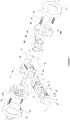
- FIG. 1 shows a latch system 1 in accordance with one embodiment of the present invention.
- a latch 10 is known per se and comprises a latch body 12 and an end plate 14.
- the end plate 14 is round and has a cylindrical section 16 adapted to be received in an edge bore (not shown) in the edge of a door panel (also not shown).
- the section 16 has knurls 18 adapted to be a press fit in the edge bore if that is appropriately sized.
- the section 16 and the edge bore have a diameter of about 25 mm.
- the end of the latch 10 has the usual latch member 20, adapted to engage a keeper in a door jamb and retain the door closed in known fashion.
- the latch body 12 has a longitudinal axis X and an operation aperture 22, which is rotatable in the body about an operation axis A which is orthogonal the longitudinal axis X.
- the operation aperture 22 has a backset B, being the separation of the axis X from the end plate 14. This is typically either 45 mm or 57mm, depending on the handle (not shown) to be employed with the door.
- a cross drilling (not shown in Figure 1 but shown at 50 in Figure 3 , in a door panel 52), is provided whereby the axis A of operation aperture 22 is arranged to be coincident with the cross-drilling.
- an adaptor 40 is first fitted in a close sliding fit in the cross drilling. It has a latch bore 42 arranged coincident with the latch axis X and with a cross section to receive the latch body (in this case substantially rectangular) when the latch is inserted in the edge bore.
- the adaptor also has a spindle hole 44 arranged coincident with the latch axis A.
- the bore 42 and the fitting of the adaptor in the cross drilling support the latch body in the cross-drilling, the support is against vertical movement and against rotation about the X axis.
- the fitting of the latch in the edge bore supports the adaptor and prevents it from rotating about the A axis.
- the operation aperture 22 is adapted to receive in a sliding fit a square-section handle spindle 30, which has a longitudinal spindle axis Y, whereby, when assembled, operation axis A and spindle axis Y are coincident.
- each rose base 60A,B mounts a handle knob 62A or a handle lever 62B.
- the form of the handle lever or knob are incidental to the present invention and are shown only in dotted lines in Figure 3 , but, whatever their form, they are mounted for (at least limited) rotation in the rose base 60A,B, through a rotary joint 64 comprising a cylindrical stem and flange 66, washer 69 and circlip 70, passing through a circular aperture 74 in the rose base 60A,B.
- a spring 76 acting between the knob/lever flange/stem 66 and the rose base 60A,B, can be arranged to bias the knob/lever 62A,B to a stop position.
- the knob/lever 62A,B has a drive aperture 63A,B to receive the ends of the handle spindle 30.
- the handle spindle passes freely through the spindle hole and though the operation aperture 22, whereby turning of the knob/lever 62A,B results in rotation about the axis Y of the spindle and operation of the operation aperture 22 to withdraw into the latch body 12 the latch member 20.
- the rose bases 60A,B each have screw holes 68 to receive two screws 80.
- the screw holes are diametrically opposed. Their heads 81 are covered by a cap 82 having a central aperture 84.
- the central aperture needs to be as large as possible because it is intended to fit over the lever 62B.
- the cap may be screwed onto thread 86 on the rose base.
- the size of the aperture 84 needs to be large because it limits the design and shape of lever 62B that the latch system can accommodate, unless, that is, it is not required that the screw heads 81 be hidden, which, largely inevitably, must be left exposed where a knob 62A is employed as that will surely not pass through the aperture 84.
- the screws 80 need to be on as large a diameter as possible, and yet there is the restriction of the diameter of the cross drilling 50 if the rose base 60A,B is to cover the drilling completely.
- extension sleeves 90 that extend from the rose bases 60A,B around the screw holes 68 and are adapted to engage U-shaped slots 92 in the edges of the adaptor 40.
- the adaptor 40 is conveniently an injection-moulded plastics component.
- the extension sleeves are a close sliding fit over a boss 94 that is internally threaded at both ends and receives the screws 80. When they are tightened, the rose bases clamp the door panel around the cross-drilling 50.
- the thickness T of the door panel is a variable parameter and the lengths of the sleeve extensions are such that and allowance L is provided so that the latch arrangement can accommodate door panels of thickness between (T-L) and T, which typically will be in the order of 35-45mm.
- the similar dimension L is also left between the screws 80, with sufficient thread provided in the boss to accommodate the thickness variation.
- the upper limit T of the allowable door panel thickness is of course dictated by the overlap between the screws 80 and the boss 94.
- the boss 94 is screwed entirely onto the left-hand screw (in the drawing) and this does not leave more than a few turns of the thread for the right screw, or indeed much overlap between the boss and the right-hand extension sleeve 90.
- the arrangement could accommodate a wider door thickness, with as much overlap between the threads of the boss and right-hand screw, and between the right-hand extension sleeve and the boss, if the boss was not screwed tightly onto the left-hand screw.
- an important interengagement that does limit the door thickness, and is not improved by repositioning of the boss 94, is between the extension sleeves 90 and the adaptor slots 92. These desirably have a significant overlap so that there is less opportunity for lateral displacement between them.
- the extension sleeves 90 are C-shaped in section, with the open part 90C facing away from the axis Y, whereby the maximum diameter D of the internal parts of the latch system 1 (ie, those parts within the cross-drilling 50) is defined by the position of the screws 80 and the thickness of the boss 94.
- the boss 94 may be provided as a separate component (as shown in the drawings), and not be integrated with the rose base 60A, is so that it can be provided in a relatively hard steel, and thereby be rendered thin, whereas the material of the rose bases 60A,B may desirably be of softer less expensive material, such as aluminum or brass.
- the dimension D is 43 mm, with the diameter of the cross drilling being 45 mm and the diameter (or minimum dimension) of the rose bases being 49 mm so that, with the cap 82 attached the final diameter is 50 mm.
- One benefit of the arrangement whereby the screws 80 and accompanying components are disposed above and below the latch body 12 is that existing latches 10 can be employed.
- One arrangement has a privacy button 100 that can affect operation of the latch 10. It may be actuated by pressing or turning and serve either to lock the operation aperture 22 (so that the knob/lever 62A,B cannot be turned) or to render its rotation disconnected from the latch member 20 so that that remains in the closed position despite turning of the knob/lever 62A,B.
- one rose base 60A,B is provided with an actuator (not shown) to actuate the button 100. This is disposed at right angles (around axis Y) in the rose base and a slot 101 is provided in the adaptor to accommodate it.
Landscapes
- Engineering & Computer Science (AREA)
- Structural Engineering (AREA)
- Securing Of Glass Panes Or The Like (AREA)
- Lock And Its Accessories (AREA)
Claims (7)
- Système de verrou de porte (10) destiné à être installé dans un panneau de porte (52) présentant un perçage transversal (50) et un trou de bord coupant le perçage transversal, le système de verrou de porte comprenant :a. un verrou de porte (12) présentant une plaque avant (14) et un corps (16), le corps présentant un axe de corps (X) et comprenant une ouverture opérationnelle (22) située à une distance de recul souhaitée (B) à partir de la plaque avant, l'ouverture opérationnelle étant agencée pour tourner dans le corps autour d'un axe opérationnel (A) orthogonal audit axe de corps ;b. un adaptateur (40) destiné à recevoir le corps de verrou de porte ;c. deux poignées (62A, B), chacune d'elles comprenant une base de rosette (60A, B) et un levier ou un bouton disposé de manière rotative dans la base de rosette ; etd. une tige de poignée (30) présentant un axe longitudinal, où :le système de verrou de porte est adapté pour être installé dans le panneau de porte de la façon suivante :i) le corps de verrou est configuré pour être reçu dans le trou de bord, la plaque avant affleurant sensiblement le bord de la porte ;ii) l'adaptateur est configuré pour s'ajuster avec un ajustement coulissant serré dans un perçage transversal de porte compris entre 40 et 50 mm, avec un passage (42) destiné à recevoir le corps de verrou afin de supporter le corps de verrou dans l'adaptateur dans le perçage transversal, et afin d'empêcher une rotation de l'adaptateur par rapport au corps de verrou autour dudit axe opérationnel (A) ; etiii) l'ouverture opérationnelle (22) et la tige de poignée (30) sont configurées de telle sorte que la tige de poignée passe à travers l'ouverture opérationnelle, grâce à quoi ledit axe opérationnel et l'axe longitudinal coïncident, et soit reçue dans chaque poignée ou bouton (62A, B), grâce à quoi une rotation de la poignée ou du bouton se traduit par une rotation de l'ouverture opérationnelle autour desdits axes et par l'actionnement du verrou, et où :des vis transversales (80) sont prévues pour serrer ensemble les bases de rosette, chaque base de rosette comprenant des trous de vis (68) disposés diamétralement opposés les uns par rapport aux autres des deux côtés dudit levier ou dudit bouton, et de telle sorte que lesdites vis transversales puissent être reçues à travers ledit perçage transversal (50) autour du corps de verrou (12) et à travers l'adaptateur (40), un manchon d'extension (90) des bases de rosette autour de chaque trou de vis, supportant lesdites vis transversales (80), et venant en prise avec l'adaptateur (92) pour localiser les bases de rosette en rotation autour desdits axes par rapport à l'adaptateur,caractérisé en ce que lesdits manchons d'extension (90) sont en forme de C (90C) le long de leur section, grâce à quoi le diamètre de la partie de la poignée à recevoir dans le perçage transversal est défini par un bossage (94) centré sur lesdits trous de vis dans lesquels lesdites vis transversales sont adaptées pour être vissées.
- Système de verrou de porte selon la revendication 1, où les trous de vis (68) de chaque base de rosette sont adaptés pour recevoir la tête (81) d'une vis qui peut tourner librement dans les trous de vis, ledit bossage (94) est un manchon distinct, fileté à partir de chaque extrémité, pour recevoir à chaque extrémité l'une desdites vis transversales (68), ledit bossage étant reçu dans un ajustement coulissant serré dans chaque manchon d'extension (90).
- Système de verrou de porte selon la revendication 2, où la réception du bossage (94) dans chaque manchon d'extension (90) est un ajustement coulissant serré pour empêcher des moments de flexion entre le bossage et le manchon d'extension dans une direction de rotation de la base de rosette autour dudit axe opérationnel (A).
- Système de verrou de porte selon l'une quelconque des revendications 1 à 3, où les trous de vis (68) sont placés d'un côté ou de l'autre d'une bride autour d'un alésage de réception de levier ou de bouton (74) de la base de rosette (60A, B), ladite bride présentant un diamètre suffisamment grand pour qu'un chapeau de couverture (82) avec une ouverture centrale correspondante (84), puisse être manoeuvré autour d'un levier après l'installation du système dans une porte pour couvrir les têtes (81) des vis transversales (80).
- Système de verrou de porte selon l'une quelconque des revendications précédentes, où la mise en prise entre le manchon d'extension (90) des bases de rosette (60A, B) et l'adaptateur, (40) est serrée pour empêcher des moments de flexion entre l'adaptateur et le manchon d'extension dans une direction de rotation de la base de rosette autour dudit axe opérationnel.
- Système de verrou de porte selon la revendication 5, où l'adaptateur présente des encoches (92) dans son bord pour recevoir lesdits manchons d'extension.
- Système de verrou de porte selon l'une quelconque des revendications précédentes, où le corps de verrou (12) présente un bouton d'intimité (100) opérationnel par un bouton sur une base de rosette, grâce à quoi l'ouverture opérationnelle (22) ne peut pas être tournée par la poignée, ou la rotation de la poignée est rendue inefficace pour actionner le verrou (10).
Applications Claiming Priority (3)
| Application Number | Priority Date | Filing Date | Title |
|---|---|---|---|
| GBGB1514818.2A GB201514818D0 (en) | 2015-08-20 | 2015-08-20 | Door latch installation |
| ITUB2015A003177A ITUB20153177A1 (it) | 2015-08-20 | 2015-08-20 | Installazione del fermo del portello |
| PCT/GB2016/052579 WO2017029520A1 (fr) | 2015-08-20 | 2016-08-19 | Installation de verrou de porte |
Publications (2)
| Publication Number | Publication Date |
|---|---|
| EP3337941A1 EP3337941A1 (fr) | 2018-06-27 |
| EP3337941B1 true EP3337941B1 (fr) | 2019-08-14 |
Family
ID=56800305
Family Applications (1)
| Application Number | Title | Priority Date | Filing Date |
|---|---|---|---|
| EP16757053.0A Not-in-force EP3337941B1 (fr) | 2015-08-20 | 2016-08-19 | Installation de verrou de porte |
Country Status (3)
| Country | Link |
|---|---|
| EP (1) | EP3337941B1 (fr) |
| AU (1) | AU2016307888B2 (fr) |
| WO (1) | WO2017029520A1 (fr) |
Family Cites Families (7)
| Publication number | Priority date | Publication date | Assignee | Title |
|---|---|---|---|---|
| CA1037516A (fr) * | 1975-08-14 | 1978-08-29 | John L. Hook | Montage de quincaillerie sur porte |
| US4854620A (en) * | 1985-08-22 | 1989-08-08 | Ogden Industries Pty., Ltd. | Door set mounting |
| US5769472A (en) * | 1996-12-30 | 1998-06-23 | Schlage Lock Company | Drive in housing halves for mounting a latch assembly in a door and a method of installing same |
| US6916053B2 (en) * | 2003-06-03 | 2005-07-12 | Globe Union Industrial Corp. | Latch lock |
| CA2664863C (fr) * | 2006-09-29 | 2013-09-03 | Giacinto Rivadossi S.P.A. In Liquidazione | Dispositif de type serrure |
| US20150015003A1 (en) * | 2013-07-11 | 2015-01-15 | Ping Hsien Tsai | Concealed fastener lockset |
| DE102013106797A1 (de) * | 2013-06-28 | 2014-12-31 | Eco Schulte Gmbh & Co. Kg | Lagerung für einen Betätigungshebel |
-
2016
- 2016-08-19 WO PCT/GB2016/052579 patent/WO2017029520A1/fr not_active Ceased
- 2016-08-19 AU AU2016307888A patent/AU2016307888B2/en active Active
- 2016-08-19 EP EP16757053.0A patent/EP3337941B1/fr not_active Not-in-force
Non-Patent Citations (1)
| Title |
|---|
| None * |
Also Published As
| Publication number | Publication date |
|---|---|
| AU2016307888A1 (en) | 2018-02-22 |
| AU2016307888B2 (en) | 2021-06-03 |
| WO2017029520A1 (fr) | 2017-02-23 |
| EP3337941A1 (fr) | 2018-06-27 |
Similar Documents
| Publication | Publication Date | Title |
|---|---|---|
| US11053711B2 (en) | Door latch installation | |
| US9845620B2 (en) | Deadbolt indicator | |
| US20240200359A1 (en) | Exit trim with simplified lever handing | |
| US10161162B2 (en) | Escutcheon mounting plate | |
| EP3988742B1 (fr) | Poignée de fenêtre ou de porte sans rosace | |
| US20140159392A1 (en) | Concealed fastener lockset | |
| US11035148B2 (en) | Return cartridge for door handles | |
| US10550607B2 (en) | Latch assembly for a sliding door | |
| EP3337941B1 (fr) | Installation de verrou de porte | |
| GB2546102A (en) | Door latch installation jig | |
| US7152891B2 (en) | Field-reversible locking mechanism | |
| EP3480393B1 (fr) | Dispositif et procédé de montage d'une poignée sur une porte ou une fenêtre | |
| AU2016201008B2 (en) | A spindle for use with a latch assembly | |
| AU2007254650B2 (en) | Strengthened cylinder lock assembly | |
| AU2018223219B2 (en) | Rim latch with cylinder lock change | |
| AU2012201881A1 (en) | Adaptable furniture turnknob | |
| AU2009212928B2 (en) | Adjustable Bolt Assembly for Use with a Cylindrical Lock Assembly | |
| US20170016247A1 (en) | Reversible Handleset Spindle Actuator And Related Method And Kit | |
| AU2015258186B2 (en) | A door furniture assembly | |
| HK1173482A (en) | Adaptable furniture turnknob | |
| NZ734788B2 (en) | A latch assembly for a sliding door | |
| HK40042602A (en) | Device and method for mounting a handle to a door or window leaf | |
| NZ756436A (en) | Rim latch with safety release selectability | |
| NZ562469A (en) | Door handle assembly that adjusts for the width of the door | |
| CA2897175A1 (fr) | Actionneur de tige de poignee reversible et methode et trousse associees |
Legal Events
| Date | Code | Title | Description |
|---|---|---|---|
| STAA | Information on the status of an ep patent application or granted ep patent |
Free format text: STATUS: THE INTERNATIONAL PUBLICATION HAS BEEN MADE |
|
| PUAI | Public reference made under article 153(3) epc to a published international application that has entered the european phase |
Free format text: ORIGINAL CODE: 0009012 |
|
| STAA | Information on the status of an ep patent application or granted ep patent |
Free format text: STATUS: REQUEST FOR EXAMINATION WAS MADE |
|
| 17P | Request for examination filed |
Effective date: 20180320 |
|
| AK | Designated contracting states |
Kind code of ref document: A1 Designated state(s): AL AT BE BG CH CY CZ DE DK EE ES FI FR GB GR HR HU IE IS IT LI LT LU LV MC MK MT NL NO PL PT RO RS SE SI SK SM TR |
|
| AX | Request for extension of the european patent |
Extension state: BA ME |
|
| GRAJ | Information related to disapproval of communication of intention to grant by the applicant or resumption of examination proceedings by the epo deleted |
Free format text: ORIGINAL CODE: EPIDOSDIGR1 |
|
| STAA | Information on the status of an ep patent application or granted ep patent |
Free format text: STATUS: GRANT OF PATENT IS INTENDED |
|
| GRAP | Despatch of communication of intention to grant a patent |
Free format text: ORIGINAL CODE: EPIDOSNIGR1 |
|
| DAV | Request for validation of the european patent (deleted) | ||
| DAX | Request for extension of the european patent (deleted) | ||
| INTG | Intention to grant announced |
Effective date: 20180803 |
|
| RAP1 | Party data changed (applicant data changed or rights of an application transferred) |
Owner name: ASSA ABLOY LIMITED |
|
| GRAJ | Information related to disapproval of communication of intention to grant by the applicant or resumption of examination proceedings by the epo deleted |
Free format text: ORIGINAL CODE: EPIDOSDIGR1 |
|
| STAA | Information on the status of an ep patent application or granted ep patent |
Free format text: STATUS: REQUEST FOR EXAMINATION WAS MADE |
|
| INTC | Intention to grant announced (deleted) | ||
| GRAP | Despatch of communication of intention to grant a patent |
Free format text: ORIGINAL CODE: EPIDOSNIGR1 |
|
| STAA | Information on the status of an ep patent application or granted ep patent |
Free format text: STATUS: GRANT OF PATENT IS INTENDED |
|
| INTG | Intention to grant announced |
Effective date: 20190221 |
|
| GRAS | Grant fee paid |
Free format text: ORIGINAL CODE: EPIDOSNIGR3 |
|
| GRAA | (expected) grant |
Free format text: ORIGINAL CODE: 0009210 |
|
| STAA | Information on the status of an ep patent application or granted ep patent |
Free format text: STATUS: THE PATENT HAS BEEN GRANTED |
|
| RBV | Designated contracting states (corrected) |
Designated state(s): AL AT BE BG CH CY CZ DE DK EE ES FI FR GR HR HU IE IS IT LI LT LU LV MC MK MT NL NO PL PT RO RS SE SI SK SM TR |
|
| RIN1 | Information on inventor provided before grant (corrected) |
Inventor name: MONAGHAN, DANIEL |
|
| AK | Designated contracting states |
Kind code of ref document: B1 Designated state(s): AL AT BE BG CH CY CZ DE DK EE ES FI FR GR HR HU IE IS IT LI LT LU LV MC MK MT NL NO PL PT RO RS SE SI SK SM TR |
|
| REG | Reference to a national code |
Ref country code: CH Ref legal event code: EP Ref country code: AT Ref legal event code: REF Ref document number: 1167223 Country of ref document: AT Kind code of ref document: T Effective date: 20190815 |
|
| REG | Reference to a national code |
Ref country code: IE Ref legal event code: FG4D |
|
| REG | Reference to a national code |
Ref country code: DE Ref legal event code: R096 Ref document number: 602016018658 Country of ref document: DE |
|
| REG | Reference to a national code |
Ref country code: NL Ref legal event code: MP Effective date: 20190814 |
|
| REG | Reference to a national code |
Ref country code: LT Ref legal event code: MG4D |
|
| PG25 | Lapsed in a contracting state [announced via postgrant information from national office to epo] |
Ref country code: FI Free format text: LAPSE BECAUSE OF FAILURE TO SUBMIT A TRANSLATION OF THE DESCRIPTION OR TO PAY THE FEE WITHIN THE PRESCRIBED TIME-LIMIT Effective date: 20190814 Ref country code: NO Free format text: LAPSE BECAUSE OF FAILURE TO SUBMIT A TRANSLATION OF THE DESCRIPTION OR TO PAY THE FEE WITHIN THE PRESCRIBED TIME-LIMIT Effective date: 20191114 Ref country code: NL Free format text: LAPSE BECAUSE OF FAILURE TO SUBMIT A TRANSLATION OF THE DESCRIPTION OR TO PAY THE FEE WITHIN THE PRESCRIBED TIME-LIMIT Effective date: 20190814 Ref country code: SE Free format text: LAPSE BECAUSE OF FAILURE TO SUBMIT A TRANSLATION OF THE DESCRIPTION OR TO PAY THE FEE WITHIN THE PRESCRIBED TIME-LIMIT Effective date: 20190814 Ref country code: BG Free format text: LAPSE BECAUSE OF FAILURE TO SUBMIT A TRANSLATION OF THE DESCRIPTION OR TO PAY THE FEE WITHIN THE PRESCRIBED TIME-LIMIT Effective date: 20191114 Ref country code: LT Free format text: LAPSE BECAUSE OF FAILURE TO SUBMIT A TRANSLATION OF THE DESCRIPTION OR TO PAY THE FEE WITHIN THE PRESCRIBED TIME-LIMIT Effective date: 20190814 Ref country code: PT Free format text: LAPSE BECAUSE OF FAILURE TO SUBMIT A TRANSLATION OF THE DESCRIPTION OR TO PAY THE FEE WITHIN THE PRESCRIBED TIME-LIMIT Effective date: 20191216 Ref country code: HR Free format text: LAPSE BECAUSE OF FAILURE TO SUBMIT A TRANSLATION OF THE DESCRIPTION OR TO PAY THE FEE WITHIN THE PRESCRIBED TIME-LIMIT Effective date: 20190814 |
|
| REG | Reference to a national code |
Ref country code: AT Ref legal event code: MK05 Ref document number: 1167223 Country of ref document: AT Kind code of ref document: T Effective date: 20190814 |
|
| PG25 | Lapsed in a contracting state [announced via postgrant information from national office to epo] |
Ref country code: AL Free format text: LAPSE BECAUSE OF FAILURE TO SUBMIT A TRANSLATION OF THE DESCRIPTION OR TO PAY THE FEE WITHIN THE PRESCRIBED TIME-LIMIT Effective date: 20190814 Ref country code: RS Free format text: LAPSE BECAUSE OF FAILURE TO SUBMIT A TRANSLATION OF THE DESCRIPTION OR TO PAY THE FEE WITHIN THE PRESCRIBED TIME-LIMIT Effective date: 20190814 Ref country code: GR Free format text: LAPSE BECAUSE OF FAILURE TO SUBMIT A TRANSLATION OF THE DESCRIPTION OR TO PAY THE FEE WITHIN THE PRESCRIBED TIME-LIMIT Effective date: 20191115 Ref country code: LV Free format text: LAPSE BECAUSE OF FAILURE TO SUBMIT A TRANSLATION OF THE DESCRIPTION OR TO PAY THE FEE WITHIN THE PRESCRIBED TIME-LIMIT Effective date: 20190814 Ref country code: IS Free format text: LAPSE BECAUSE OF FAILURE TO SUBMIT A TRANSLATION OF THE DESCRIPTION OR TO PAY THE FEE WITHIN THE PRESCRIBED TIME-LIMIT Effective date: 20191214 Ref country code: ES Free format text: LAPSE BECAUSE OF FAILURE TO SUBMIT A TRANSLATION OF THE DESCRIPTION OR TO PAY THE FEE WITHIN THE PRESCRIBED TIME-LIMIT Effective date: 20190814 |
|
| REG | Reference to a national code |
Ref country code: DE Ref legal event code: R119 Ref document number: 602016018658 Country of ref document: DE |
|
| PG25 | Lapsed in a contracting state [announced via postgrant information from national office to epo] |
Ref country code: TR Free format text: LAPSE BECAUSE OF FAILURE TO SUBMIT A TRANSLATION OF THE DESCRIPTION OR TO PAY THE FEE WITHIN THE PRESCRIBED TIME-LIMIT Effective date: 20190814 |
|
| PG25 | Lapsed in a contracting state [announced via postgrant information from national office to epo] |
Ref country code: IT Free format text: LAPSE BECAUSE OF FAILURE TO SUBMIT A TRANSLATION OF THE DESCRIPTION OR TO PAY THE FEE WITHIN THE PRESCRIBED TIME-LIMIT Effective date: 20190814 Ref country code: PL Free format text: LAPSE BECAUSE OF FAILURE TO SUBMIT A TRANSLATION OF THE DESCRIPTION OR TO PAY THE FEE WITHIN THE PRESCRIBED TIME-LIMIT Effective date: 20190814 Ref country code: AT Free format text: LAPSE BECAUSE OF FAILURE TO SUBMIT A TRANSLATION OF THE DESCRIPTION OR TO PAY THE FEE WITHIN THE PRESCRIBED TIME-LIMIT Effective date: 20190814 Ref country code: DK Free format text: LAPSE BECAUSE OF FAILURE TO SUBMIT A TRANSLATION OF THE DESCRIPTION OR TO PAY THE FEE WITHIN THE PRESCRIBED TIME-LIMIT Effective date: 20190814 Ref country code: EE Free format text: LAPSE BECAUSE OF FAILURE TO SUBMIT A TRANSLATION OF THE DESCRIPTION OR TO PAY THE FEE WITHIN THE PRESCRIBED TIME-LIMIT Effective date: 20190814 Ref country code: RO Free format text: LAPSE BECAUSE OF FAILURE TO SUBMIT A TRANSLATION OF THE DESCRIPTION OR TO PAY THE FEE WITHIN THE PRESCRIBED TIME-LIMIT Effective date: 20190814 |
|
| PG25 | Lapsed in a contracting state [announced via postgrant information from national office to epo] |
Ref country code: CZ Free format text: LAPSE BECAUSE OF FAILURE TO SUBMIT A TRANSLATION OF THE DESCRIPTION OR TO PAY THE FEE WITHIN THE PRESCRIBED TIME-LIMIT Effective date: 20190814 Ref country code: SK Free format text: LAPSE BECAUSE OF FAILURE TO SUBMIT A TRANSLATION OF THE DESCRIPTION OR TO PAY THE FEE WITHIN THE PRESCRIBED TIME-LIMIT Effective date: 20190814 Ref country code: CH Free format text: LAPSE BECAUSE OF NON-PAYMENT OF DUE FEES Effective date: 20190831 Ref country code: LI Free format text: LAPSE BECAUSE OF NON-PAYMENT OF DUE FEES Effective date: 20190831 Ref country code: MC Free format text: LAPSE BECAUSE OF FAILURE TO SUBMIT A TRANSLATION OF THE DESCRIPTION OR TO PAY THE FEE WITHIN THE PRESCRIBED TIME-LIMIT Effective date: 20190814 Ref country code: SM Free format text: LAPSE BECAUSE OF FAILURE TO SUBMIT A TRANSLATION OF THE DESCRIPTION OR TO PAY THE FEE WITHIN THE PRESCRIBED TIME-LIMIT Effective date: 20190814 Ref country code: LU Free format text: LAPSE BECAUSE OF NON-PAYMENT OF DUE FEES Effective date: 20190819 Ref country code: IS Free format text: LAPSE BECAUSE OF FAILURE TO SUBMIT A TRANSLATION OF THE DESCRIPTION OR TO PAY THE FEE WITHIN THE PRESCRIBED TIME-LIMIT Effective date: 20200224 |
|
| REG | Reference to a national code |
Ref country code: BE Ref legal event code: MM Effective date: 20190831 |
|
| PLBE | No opposition filed within time limit |
Free format text: ORIGINAL CODE: 0009261 |
|
| STAA | Information on the status of an ep patent application or granted ep patent |
Free format text: STATUS: NO OPPOSITION FILED WITHIN TIME LIMIT |
|
| PG2D | Information on lapse in contracting state deleted |
Ref country code: IS |
|
| PG25 | Lapsed in a contracting state [announced via postgrant information from national office to epo] |
Ref country code: DE Free format text: LAPSE BECAUSE OF NON-PAYMENT OF DUE FEES Effective date: 20200303 Ref country code: IE Free format text: LAPSE BECAUSE OF NON-PAYMENT OF DUE FEES Effective date: 20190819 |
|
| 26N | No opposition filed |
Effective date: 20200603 |
|
| PG25 | Lapsed in a contracting state [announced via postgrant information from national office to epo] |
Ref country code: BE Free format text: LAPSE BECAUSE OF NON-PAYMENT OF DUE FEES Effective date: 20190831 Ref country code: SI Free format text: LAPSE BECAUSE OF FAILURE TO SUBMIT A TRANSLATION OF THE DESCRIPTION OR TO PAY THE FEE WITHIN THE PRESCRIBED TIME-LIMIT Effective date: 20190814 |
|
| PG25 | Lapsed in a contracting state [announced via postgrant information from national office to epo] |
Ref country code: FR Free format text: LAPSE BECAUSE OF NON-PAYMENT OF DUE FEES Effective date: 20191014 |
|
| PG25 | Lapsed in a contracting state [announced via postgrant information from national office to epo] |
Ref country code: CY Free format text: LAPSE BECAUSE OF FAILURE TO SUBMIT A TRANSLATION OF THE DESCRIPTION OR TO PAY THE FEE WITHIN THE PRESCRIBED TIME-LIMIT Effective date: 20190814 |
|
| PG25 | Lapsed in a contracting state [announced via postgrant information from national office to epo] |
Ref country code: MT Free format text: LAPSE BECAUSE OF FAILURE TO SUBMIT A TRANSLATION OF THE DESCRIPTION OR TO PAY THE FEE WITHIN THE PRESCRIBED TIME-LIMIT Effective date: 20190814 Ref country code: HU Free format text: LAPSE BECAUSE OF FAILURE TO SUBMIT A TRANSLATION OF THE DESCRIPTION OR TO PAY THE FEE WITHIN THE PRESCRIBED TIME-LIMIT; INVALID AB INITIO Effective date: 20160819 |
|
| PG25 | Lapsed in a contracting state [announced via postgrant information from national office to epo] |
Ref country code: MK Free format text: LAPSE BECAUSE OF FAILURE TO SUBMIT A TRANSLATION OF THE DESCRIPTION OR TO PAY THE FEE WITHIN THE PRESCRIBED TIME-LIMIT Effective date: 20190814 |