EP3338433B1 - Appareil et procédé de surveillance de région interactive configurable par l'utilisateur - Google Patents
Appareil et procédé de surveillance de région interactive configurable par l'utilisateur Download PDFInfo
- Publication number
- EP3338433B1 EP3338433B1 EP16839506.9A EP16839506A EP3338433B1 EP 3338433 B1 EP3338433 B1 EP 3338433B1 EP 16839506 A EP16839506 A EP 16839506A EP 3338433 B1 EP3338433 B1 EP 3338433B1
- Authority
- EP
- European Patent Office
- Prior art keywords
- interactive region
- event
- user
- predetermined
- interactive
- Prior art date
- Legal status (The legal status is an assumption and is not a legal conclusion. Google has not performed a legal analysis and makes no representation as to the accuracy of the status listed.)
- Active
Links
Images


Classifications
-
- H—ELECTRICITY
- H04—ELECTRIC COMMUNICATION TECHNIQUE
- H04L—TRANSMISSION OF DIGITAL INFORMATION, e.g. TELEGRAPHIC COMMUNICATION
- H04L12/00—Data switching networks
- H04L12/28—Data switching networks characterised by path configuration, e.g. LAN [Local Area Networks] or WAN [Wide Area Networks]
- H04L12/2803—Home automation networks
- H04L12/2816—Controlling appliance services of a home automation network by calling their functionalities
- H04L12/282—Controlling appliance services of a home automation network by calling their functionalities based on user interaction within the home
-
- G—PHYSICS
- G06—COMPUTING OR CALCULATING; COUNTING
- G06F—ELECTRIC DIGITAL DATA PROCESSING
- G06F3/00—Input arrangements for transferring data to be processed into a form capable of being handled by the computer; Output arrangements for transferring data from processing unit to output unit, e.g. interface arrangements
- G06F3/01—Input arrangements or combined input and output arrangements for interaction between user and computer
- G06F3/017—Gesture based interaction, e.g. based on a set of recognized hand gestures
-
- G—PHYSICS
- G06—COMPUTING OR CALCULATING; COUNTING
- G06F—ELECTRIC DIGITAL DATA PROCESSING
- G06F3/00—Input arrangements for transferring data to be processed into a form capable of being handled by the computer; Output arrangements for transferring data from processing unit to output unit, e.g. interface arrangements
- G06F3/01—Input arrangements or combined input and output arrangements for interaction between user and computer
- G06F3/011—Arrangements for interaction with the human body, e.g. for user immersion in virtual reality
-
- H—ELECTRICITY
- H04—ELECTRIC COMMUNICATION TECHNIQUE
- H04W—WIRELESS COMMUNICATION NETWORKS
- H04W4/00—Services specially adapted for wireless communication networks; Facilities therefor
- H04W4/02—Services making use of location information
- H04W4/021—Services related to particular areas, e.g. point of interest [POI] services, venue services or geofences
-
- H—ELECTRICITY
- H04—ELECTRIC COMMUNICATION TECHNIQUE
- H04W—WIRELESS COMMUNICATION NETWORKS
- H04W4/00—Services specially adapted for wireless communication networks; Facilities therefor
- H04W4/30—Services specially adapted for particular environments, situations or purposes
- H04W4/33—Services specially adapted for particular environments, situations or purposes for indoor environments, e.g. buildings
-
- G—PHYSICS
- G06—COMPUTING OR CALCULATING; COUNTING
- G06V—IMAGE OR VIDEO RECOGNITION OR UNDERSTANDING
- G06V40/00—Recognition of biometric, human-related or animal-related patterns in image or video data
- G06V40/20—Movements or behaviour, e.g. gesture recognition
-
- H—ELECTRICITY
- H04—ELECTRIC COMMUNICATION TECHNIQUE
- H04L—TRANSMISSION OF DIGITAL INFORMATION, e.g. TELEGRAPHIC COMMUNICATION
- H04L12/00—Data switching networks
- H04L12/28—Data switching networks characterised by path configuration, e.g. LAN [Local Area Networks] or WAN [Wide Area Networks]
- H04L12/2803—Home automation networks
- H04L2012/284—Home automation networks characterised by the type of medium used
- H04L2012/2841—Wireless
Definitions
- This disclosure generally relates to electronic event detection.
- a depth sensor may generate a depth image that includes an array of pixels corresponding to regions of a physical environment with a depth value for each pixel indicating the depth of the corresponding region.
- Depth images may be generated by stereo triangulation, sheet of light triangulation, structured light, interferometry, coded aperture, or other means.
- Connected devices may be part of a communication network such as a local area network, wide area network, cellular network, the Internet, or any other suitable network.
- a connected device may use a communication network to communicate with other devices, for example, to access remotely-stored data, access remote processing power, access remote displays, provide locally-stored data, provide local processing power, or provide access to local displays.
- networks may provide communication paths and links to servers, which may host applications, content, and services that may be accessed or utilized by connected devices.
- the content may include text, video data, audio data, user settings or other types of data.
- Networks may use any suitable communication protocol or technology to facilitate communication between connected devices, such as, for example, BLUETOOTH, IEEE WI-FI (802.11a/b/g/n/ac), or TCP/IP.
- WO 2015/117852 A1 relates to a method of operating a control system for controlling a device comprising motion capture equipment
- US 2015/002388 A1 relates to an interactive zone-based installation for enabling a user to interact with an object
- WO 2015/113833 A1 relates to using motion sensors to provide a utility into a space occupied by a user
- WO 2012/121433 A1 relates to a controller for a display device with a controller configured to perform functions according to gestures made by an external object.
- An embodiment provides an apparatus comprising: a first sensor comprising a depth sensor, one or more computer-readable storage media embodying instructions, and one or more processors configured to execute the instructions to: monitor, at least in part by output of the depth sensor, a physical environment comprising a user-defined interactive region for a predetermined event, detect, at least in part by the output of the depth sensor, the predetermined event in the interactive region, and in response to detection of the predetermined event, initiate a predetermined action associated with the predetermined event, wherein the predetermined event comprises a plurality of event conditions characterised in that the apparatus comprises a second sensor for detecting an environmental condition and in that the plurality of event conditions includes an event determined from the output of the second sensor used for detecting an environmental condition.
- the one or more processors are further configured to execute the instructions to identify the interaction region based on user input.
- the one or more processors are further configured to execute the instructions to: in response to receiving the input identifying the interactive region, allocate, based at least in part on a monitoring load, resources for monitoring the interactive region.
- the input is based at least in part on a gesture performed in the physical environment by the user.
- the input is based at least in part on an interaction between the user and a user interface displayed on a client system.
- one or more of: the predetermined action is defined at least in part by a user, or the association of the predetermined action with the predetermined event is defined at least in part by the user.
- processors that are configured to execute the instructions to monitor the interactive region for a predetermined event further comprise processors that are configured to execute the instructions to: monitor the interactive region for a threshold event, and in response to detection of the threshold event, monitor the interactive region for the predetermined event.
- the predetermined event comprises a plurality of event conditions, at least one event condition corresponding to the interactive region.
- the predetermined event comprises one or more of: a presence of an object or a user in the interactive region, a movement of an object or a user within the interactive region, or contact between a user and at least a portion of an object within the interactive region.
- the one or more processors are further configured to execute the instructions to periodically monitor, at least in part by output of the depth sensor, a plurality of interactive regions according to a priority associated with each interactive region.
- a first priority associated with a first interactive region is based at least in part on one or more of: historical event data associated with the first interactive region, an expected frequency of one or more predetermined events in the first interactive region, an expected duration of one or more predetermined events in the first interactive region, or an importance of the first interactive region.
- the one or more processors are further configured to execute the instructions to monitor, at least in part by the depth sensor, a physical environment comprising a user-defined interactive region for each of a plurality of predetermined events according to a priority associated with each event.
- the interactive region comprises a first interactive region, at least a portion of the first interactive region comprises at least a portion of a second interactive region associated with one or more second-region predetermined events, and the processors are further configured to execute the instructions to detect, based on data created by monitoring the portion of the first interactive region, one or more second-region predetermined events in the portion of the second interactive region.
- the physical environment is the user-defined interactive region.
- An embodiment provides one or more computer-readable storage media embodying instructions that when executed by one or more processors cause the one or more processors to perform operations comprising: monitoring, based at least in part on output from a depth sensor, a physical environment comprising a user-defined interactive region for a predetermined event, detecting, based at least in part on output from the depth sensor, the predetermined event in the interactive region, and in response to detection of the predetermined event, initiating a predetermined action associated with the predetermined wherein the predetermined event comprises a plurality of event conditions, characterised in that the plurality of event conditions includes an event determined from the output of a second sensor, wherein the second sensor is used for detecting an environmental condition.
- the operations further comprise identifying the interaction region based on user input.
- one or more of: the predetermined action is defined at least in part by a user, or the association of the predetermined action with the predetermined event is defined at least in part by the user.
- An embodiment provides a method comprising: monitoring, at least in part by an output of a depth sensor, a physical environment comprising a user-defined interactive region for a predetermined event, detecting, at least in part by the output of the depth sensor, the predetermined event in the interactive region, and in response to detection of the predetermined event, automatically initiating a predetermined action associated with the predetermined wherein the predetermined event comprises a plurality of event conditions, characterised in that the plurality of event conditions includes an event determined from the output of a second sensor, wherein the second sensor is used for detecting an environmental condition.
- the method further comprises identifying the interactive region based on user input.
- one or more of: the predetermined action is defined at least in part by a user, or the association of the predetermined action with the predetermined event is defined at least in part by the user.
- the interactive regions may be monitored by an interactive region monitoring system for one or more predetermined events, such as, for example, events that have been defined by a user, automatically defined by a computing device, or both.
- the interactive region monitoring system may include one or more depth sensors.
- a predetermined action may be initiated by the interactive region monitoring system.
- the interactive region monitoring system communicates electronically with another connected device to initiate the action.
- An interactive region monitoring system may include one or more depth sensors, connected devices, servers, client systems, or any other devices or systems.
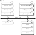
- FIG. 1 illustrates an example network environment 100 for particular embodiments of an interactive region monitoring system.
- Network environment 100 may include connected devices 130, data store 140, interactive region monitoring server 150, and sensors 160 connected to each other by network 110.
- FIG. 1 illustrates a particular arrangement of connected devices 130, data store 140, interactive region monitoring server 150, and sensors 160, this disclosure contemplates any suitable arrangement of connected devices 130, data store 140, interactive region monitoring server 150, and sensors 160.
- two or more of connected devices 130, data store 140, interactive region monitoring server 150, and sensors 160 may be connected to each other directly, bypassing network 110.
- two or more of connected devices 130, data store 140, interactive region monitoring server 150, and sensors 160 may be physically or logically co-located with each other in whole or in part.
- data store 140 may be directly connected to or co-located with interactive region monitoring server 150.
- one or more sensors 160 may be directly connected to or co-located with one or more connected devices 130.
- FIG. 1 illustrates a particular number of connected devices 130, data stores 140, interactive region monitoring servers 150, sensors 160, and networks 110 this disclosure contemplates any suitable number of connected devices 130, data stores 140, interactive region monitoring servers 150, sensors 160, and networks 110.
- network environment 100 may include multiple connected devices 130, data stores 140, interactive region monitoring servers 150, sensors 160, and networks 110.
- network 110 may include any suitable network 110.
- one or more portions of network 110 may include an ad hoc network, an intranet, an extranet, a virtual private network (VPN), a local area network (LAN), a wireless LAN (WLAN), a wide area network (WAN), a wireless WAN (WWAN), a metropolitan area network (MAN), a portion of the Internet, a portion of the Public Switched Telephone Network (PSTN), a cellular telephone network, or a combination of two or more of these.
- Network 110 may include one or more networks 110.
- Links 120 may connect connected devices 130, data store 140, interactive region monitoring server 150, and sensors 160 to communication network 110 or to each other.
- This disclosure contemplates any suitable links 120.
- one or more links 120 include one or more wireline (such as for example Digital Subscriber Line (DSL) or Data Over Cable Service Interface Specification (DOCSIS)), wireless (such as for example Wi-Fi or Worldwide Interoperability for Microwave Access (WiMAX)), or optical (such as for example Synchronous Optical Network (SONET) or Synchronous Digital Hierarchy (SDH)) links.
- wireline such as for example Digital Subscriber Line (DSL) or Data Over Cable Service Interface Specification (DOCSIS)
- wireless such as for example Wi-Fi or Worldwide Interoperability for Microwave Access (WiMAX)
- optical such as for example Synchronous Optical Network (SONET) or Synchronous Digital Hierarchy (SDH) links.
- SONET Synchronous Optical Network
- SDH Synchronous Digital Hierarchy
- one or more links 120 each include an ad hoc network, an intranet, an extranet, a VPN, a LAN, a WLAN, a WAN, a WWAN, a MAN, a portion of the Internet, a portion of the PSTN, a cellular technology-based network, a satellite communications technology-based network, another link 120, or a combination of two or more such links 120.
- Links 120 need not necessarily be the same throughout network environment 100.
- One or more first links 120 may differ in one or more respects from one or more second links 120.
- a link 120 to connected device 130a may differ from a link 120 to connected device 130b and 130c.
- a link 120 to sensor 160a may differ in one or more respects from a link 120 to sensor 160b and 160c.
- an interactive region monitoring system may include one or more connected devices 130, data stores 140, interactive region monitoring servers 150, or sensors 160.
- an interactive region monitoring system may be connected to one or more connected devices 130.
- Connected devices 130 may include, without limitation, a television set, a mobile device such as a smartphone or tablet, a personal computer, a laptop computer, a gaming console, a thermostat, a media device, or any other appropriate device.
- Connected devices 130 may, as an example, communicate with network 110 via a wireless communications protocol, such as Wi-Fi or BLUETOOTH.
- interactive region monitoring server 150 may send an instruction to a connected device, such as an instruction to: turn on, turn off, tune to a particular channel, play audio, play video, or any other instruction.
- an interactive region monitoring system may be connected to one or more sensors 160.
- Sensors 160 may include any appropriate sensor, include as an example and not by way of limitation, a depth sensor, an image sensor, a digital camera, a red-green-blue (RGB) camera, an infrared camera, a time-of-flight camera, a structured-light camera, a laser scanner, a radar, a LIDAR, a sonar, a proximity sensor, a motion detector, any other suitable sensor, or any suitable combination thereof.
- Sensors 160 may send data to interactive region monitoring server 150.
- data store 140 may include networked storage, as illustrated in FIG. 1 , such as cloud storage or other network accessible storage. Additionally or alternatively, data store 140 may include local storage within or directly attached to interactive region monitoring server 150, such as solid state drives (“SSDs”) or hard disk drives (“HDDs”).
- SSDs solid state drives
- HDDs hard disk drives
- data store 140 may store a data structure corresponding to an interactive region.
- a data structure may include, as an example and not be way of limitation, a point cloud, a wire-frame model, a parametric-based model, a boundary representation, a binary space partitioning tree, a k-dimensional tree, an octree, a constructive solid geometry tree, a grid, a polygon mesh model, a surface model, a solid computer-aided design (CAD) model, or any other suitable data structure.
- CAD computer-aided design
- data store 140 may store template data corresponding to an event or event condition.
- a data structure may include, as an example and not by way of limitation, a template image or template skeletal tracking data.
- data store 140 may store algorithmic data corresponding to an event condition.
- data store 140 may store an algorithm that corresponds to an event condition that is a of a user's hand moving to the left at least 13 inches and then moving up at least 5 inches, but only if the time delay between the two movements is less than 1.3 seconds and only if the rest of the user's is relatively stable.
- data store 140 may store data corresponding to an action.
- data may include data about one or more connected devices 130.
- data may include a unique device identifier, information about the user of a connected device 130, device details (e.g., manufacturer, operating system, localized language, audio-visual capabilities, battery capacity, network connectivity specifications, etc.), details about software applications on a connected device (e.g., name, version, maximum message size, etc.), or other appropriate device data.
- data store 140 may store data about an application programming interface (API) that corresponds to one or more connected devices 130 or one or more software applications configured to run on one or more connected devices 130.
- API application programming interface
- data store 140 may store data that indicates an association between interactive regions, predetermined events, and predetermined actions.
- data store 140 stores historical data. Historical data may include (1) one or more interactive regions that have been created and/or in which user interaction has occurred; (2) a time, date, or duration of user interactions; (3) data from an interactive region monitoring system; (4) information about predetermined events or event conditions; (5) information about predetermined actions; or (6) any other appropriate data, or any suitable combination thereof.
- interactive region monitoring server 150 communicates with one or more sensors 160. In some embodiments, interactive region monitoring server 150 communicates to one or more sensors 160 instructions to monitor an interactive region. For example, interactive region monitoring server 150 may communicate with data store 140 and retrieve a data structure corresponding to an interactive region. Based on the data structure, interactive region monitoring server 150 may direct one or more sensors 160 to monitor the corresponding interactive region for one or more event or event conditions. In some embodiments, sensors 160 may not monitor portions of a physical environment that do not correspond to an interactive region.
- an interactive region service 152 of interactive region monitoring server 150 may generate an appropriate form for communication with sensors 160 or data store 140.
- interactive region service 152 may retrieve data from data store 140 that corresponds to an interactive region.
- Interactive region service 152 may also retrieve data from one or more sensors 160. Based on a comparison of the data corresponding to an interactive region and the data from one or more sensors 160, interactive region service 152 may instruct one or more sensors 160 to monitor an interactive region.
- an event detection service 154 of interactive region monitoring server 150 may determine whether an event condition has occurred based on template data. For example, event detection service 154 may retrieve template data corresponding to an event condition from data store 140. Template data may include data from exemplars of an event condition (e.g., using data based on an exemplar provided by a user). Event detection service 154 may then compare the template data to the data retrieved from one or more sensors 160 to determine whether the event condition is detected. Additionally or alternatively, event detection service 154 may determine whether an event condition has occurred based on template data or algorithmic data corresponding to an event condition, as described above. In some embodiments, event detection service 154 may detect a predetermined event by determining one or more event conditions associated with the predetermined event and based on the detection of the one or more event conditions.
- interactive region monitoring server 150 communicates with one or more connected devices 130. In some embodiments, interactive region monitoring server 150 communicates to one or more connected devices 130 to initiate a predetermined action. For example, interactive region monitoring server 150 may communicate with data store 140 and retrieve data corresponding to a predetermined action. Based on the data, interactive region monitoring server 150 may send an instruction to one or more connected devices 130 to initiate a predetermined action.
- an action initiation service 156 of interactive region monitoring server 150 may initiate a predetermined action based on an association between interactive regions, events, and actions.
- action initiation service 156 may retrieve data from data store 140 that indicates an association between interactive regions, events, and actions.
- Action initiation service 156 may also receive data from interactive region service 152 and event detection service 154 that indicates that an event in an associated interactive region has been detected. Based on this, action initiation service 156 may use the data indicating an association between interactive regions, predetermined events, and predetermined actions to cross-reference the interactive region and predetermined event with the associated predetermined action.
- Action initiation service 156 may then initiate the associated predetermined action.
- an action initiation service 156 may determine an association between interactive regions, events, and actions based on a record for an interactive region.
- the interactive region monitoring system maintains a data structure that includes a number of records (e.g., by storing the record in data store 140 and updating the record via instructions from interactive region monitoring server 150).
- Each record may define one or more interactive regions for monitoring and may be linked to one or more users.
- each record can include data indicative of the coordinates of the interactive region, an event that triggers an action, the action that occurs in response to the event, and, in some embodiments, the device that performs the action.
- the interactive region monitoring system may generate a record based on user input ( e.g., when a user configures an interactive region, defines an event, defines an action, etc.).
- an action initiation service 156 may initiate an action by generating an appropriate instruction to send to one or more connected devices 130.
- action initiation service 156 may retrieve data from data store 140 that corresponds to a predetermined action. The action may be performed by one or more of connected devices 130.
- Action initiation service may also retrieve from data store 140 about the one or more connected devices 130.
- action initiation service may initiate an action by determining an appropriate instruction and sending that instruction to a connected device. For example, data about a mobile phone may include a phone number.
- the action initiation service may use the phone number to uniquely identify the mobile phone for delivery of the text message (e.g ., by emailing a short message service (SMS) gateway).
- SMS short message service
- FIG. 2 illustrates an example embodiment of an interactive region in an example physical environment.
- depth sensor 210 generates a depth image as an output.
- a depth image may be an array of pixels corresponding to regions of a physical environment with a depth value for each pixel indicating the depth of the corresponding region.
- a depth image may be generated, as an example and not by way of limitation, by: stereo triangulation, sheet of light triangulation, structured light, interferometry, coded aperture, or any other appropriate means of detecting a depth image.
- depth sensor 210 may include or be a part of an electronic system which includes an image sensor, a digital camera, a red-green-blue (RGB) camera, an infrared camera, a time-of-flight camera, a structured-light camera, a laser scanner, a radar, a LIDAR, a sonar, a proximity sensor, a motion detector, any other suitable sensor, or any suitable combination thereof.
- depth sensor 210 (or an electronic system of which depth sensor 210 is a part) may also detect sound, chemical particles, electric current, electric potential, magnetic fields, air flow, light, pressure, force, temperature, heat, motion, images, time, date, biometric data, or any other data.
- depth sensor 210 (or an electronic system of which depth sensor 210 is a part) may detect data about the movement of objects or people or the speed of objects or people.
- an interactive region monitoring system may monitor ( e.g., by depth sensor 210) one or more interactive regions, such as interactive region 220, for one or more predetermined events.
- An interactive region may take any suitable size, shape, or location within physical environment. As illustrated in FIG. 2 , in particular embodiments an interactive region may be defined by a three-dimensional shape. In particular embodiments, an interactive region may be (or very nearly be) a surface, such as the surface of a table.
- an interactive region monitoring system may monitor ( e.g., by depth sensor 210) one or more interactive regions, such as interactive region 220, for one or more predetermined events.
- a predetermined event may consist of two or more event conditions that collectively make up the event, i.e., a predetermined action may be initiated only when multiple events (which collectively are the predetermined event) are detected.
- a predetermined event may occur within an interactive region when one or more event conditions making up the predetermined event occur within the interactive region.
- a predetermined event may include two event conditions: 1) that a particular user enter an interactive region around or on a desk chair; and 2) that the temperature in the room be more than a threshold temperature.
- both event conditions may be required to trigger a predetermined action, such as turning on a fan or air conditioner.
- a predetermined event may be equivalent to an event condition or that a predetermined event may require the occurrence of multiple event conditions.
- This disclosure contemplates that, where suitable, disclosure relating to event conditions applies to predetermined events, and vice versa.
- predetermined events and/or event conditions may include: movement within an interactive region, the presence or absence of an object or person within an interactive region, an object or person entering an interactive region, an object or person leaving an interactive region, or any other suitable event condition.
- an event condition may be that other event conditions occur a particular order, within a particular time of one another, or any other relational condition.
- an event condition may include output from any sensor or device, such as the sensors or devices illustrated in Fig. 1 .
- one or more event conditions may be determined by a user, e.g., from a list of event conditions.
- an interactive region monitoring system may detect a predetermined event by receiving data from depth sensor 210, a connected device, or by a combination of devices that indicate that event conditions have occurred.
- a list of event conditions may include event conditions that do not require resource-intensive image processing, such as movement, a level of brightness, an object or user entering or leaving the interactive region, or any other suitable event.
- an event condition may include recognizing a particular object or object type, recognizing a user (such as the user's face or a client system of the user), recognizing a particular gesture or body position, or any other event condition.
- a predetermined event or an event condition may not be detected unless a threshold event is detected.
- Detecting a threshold event may include receiving information (e.g., from a depth sensor, a connected device, a database, etc.) that a threshold event has been detected.
- an interactive region monitoring system may monitor interactive region 220 via depth sensor 210 to detect the presence of a person as a threshold event.
- the interactive region monitoring system may monitor interactive region 220 for particular user 230, for example, by processing the image captured by the depth sensor using facial recognition, which may be more resource-intensive to accomplish than is detection and processing of the triggering event.
- a relatively low resource-intensive threshold event may be detected and processed before one or more relatively resource-intensive tasks associated with detecting an event, thereby conserving computer resources during periods where the threshold event is not detected.
- one or more connected devices communicatively coupled to the interactive region monitoring system may be used to detect a predetermined event or an event condition.
- a particular user may have a connected device which communicates information that uniquely identifies its user.
- user 230 may have a mobile phone, smart watch, tablet, laptop, or other device that communicates to an interactive region monitoring system (e.g., via BLUETOOTH) a unique identifier (e.g. a username, a phone number, a media access control (MAC) address, etc.) that identifies user 230.
- the interactive region monitoring system may determine whether a threshold condition has occurred.
- the interactive region monitoring system may broadcast a request for proximate connected devices to reply with information that uniquely identifies their users or the respective user devices.
- an interactive region may be associated with one or more particular users.
- an interactive region might be associated with user 230.
- the association may be determined from a data store, such as data store 140, that correlates the region and the user, for example through a profile for the user, a profile for the region, or both.
- the interactive region may not be monitored for a predetermined event unless a particular user's presence is detected in the interactive region.
- a user's presence may be detected by, for example, facial recognition.
- interactive region may broadcast a request for proximate connected devices to reply with information that uniquely identifies the user or users of the connected device.
- the interactive region may be monitored for a predetermined event only if a proximate connected device identifies the particular user associated with the interactive region. Additionally or alternatively, an interactive region may not be associated with any particular user.
- an interactive region monitoring system may monitor an interactive region only when a threshold event is detected. For example, an interactive region may only be monitored during certain times of day, if an on/off toggle is on, or if any other event condition or predetermined event is satisfied.
- a predetermined action may be initiated by an interactive region monitoring system when a predetermined event is detected, for example when one or more event conditions for the predetermined event are detected.
- Event conditions may include detecting a predetermined event within an interactive region and may include one or more other event conditions, such as the time of day; output from a device (such as a smartphone, watch, appliance, etc.); an environmental condition such as light, noise, temperature, etc.; or any other suitable event condition.
- a predetermined action may be performed by an interactive region monitoring system, by a device connected to an interactive region monitoring system, by a depth sensor, or by any other suitable device.
- an interactive region monitoring system including depth sensor 210 may monitor interactive region 220 for the predetermined event of a user entering interactive region 220.
- the interactive region monitoring system may also connect to TV 240.
- the interactive region monitoring system may initiate the predetermined action of TV 240 turning on by sending an instruction to TV 240.
- a predetermined action may include delivering a message or reminder to a user.
- user 230 may have a history of watching the show 'Game of Thrones.' If user 230 enters interactive region 220, an interactive region monitoring system may initiate the playing of an audio reminder that informs user 230 that the season premiere of 'Game of Thrones' will start in 10 minutes.
- a predetermined event may include multiple event conditions.
- one event condition may be that other event conditions occur a particular order, within a particular time of one another, or any other relational condition.
- an interactive region may be monitored for multiple predetermined events, each of which triggers a predetermined action.
- an interactive region monitoring system may be monitoring interactive region 220 via depth sensor 210 for the predetermined event including the event condition of a user entering interactive region 220. When the event condition is satisfied by the detection of a user entering interactive region 220, the interactive region monitoring system may initiate the predetermined action of turning on TV 240.
- the interactive region monitoring system may be monitoring interactive region 220 for an additional predetermined event including the event condition that particular user 230 enters interactive region 220. If user 230 enters interactive region 220, then the interactive region monitoring system may initiate the predetermined action of tuning TV 240 to a particular channel particular to user 230. As another example, an interactive region monitoring system may be monitoring interactive region 220 for the predetermined event including the event conditions of a user leaving and TV 240 being on. If the interactive region monitoring system detects that TV 240 is on and that a user left interactive region 220, the interactive region monitoring system may initiate the predetermined action of pausing video content on TV 240.
- an interactive region monitoring system may enhance a physical object or surface in an environment.
- an interactive region monitoring system may enhance a retail store display by allowing a user to touch or come near a particular item and displaying the price for the item in response.
- the interactive region would include all or some of the item or a space near the item, the predetermined event would be contacting or coming near the item, and the predetermined action would be displaying the price of the item.
- an interactive region monitoring system may be used in a museum to link objects to content on an audio tour.
- an interactive region monitoring system may be used in a classroom to link different parts of the inside of a computer to different video tutorials or to the display of more detailed information about a particular computer component.
- an interactive region monitoring system may be used at a corporate event when unveiling a new product to trigger appropriate content in a presentation when interaction with a prototype of the product, such as touching the prototype, occurs.
- an interactive region may include any suitable space or combination of spaces; a predetermined event may include one or more suitable event conditions; and a predetermined action corresponding to a predetermined event may include any suitable one or more actions.
- FIG. 3A-D illustrates example embodiments of user 230 configuring an interactive region.
- configuring an interactive region may include determining an interactive region (e.g., determining the shape, area, location, size, orientation, position, or other properties of an interactive region), moving an existing interactive region, modifying an existing interactive region, or deleting an existing interactive region.
- an interactive region monitoring system may store data that represents properties of an interactive region.
- an interactive region monitoring system may store a data structure corresponding to an interactive region (e.g., a point cloud, a wire-frame model, a parametric-based model, a boundary representation, a binary space partitioning tree, a k-dimensional tree, an octree, a constructive solid geometry tree, a grid, a polygon mesh model, a surface model, a solid computer-aided design (CAD) model, or any other suitable data structure).
- a data structure corresponding to an interactive region e.g., a point cloud, a wire-frame model, a parametric-based model, a boundary representation, a binary space partitioning tree, a k-dimensional tree, an octree, a constructive solid geometry tree, a grid, a polygon mesh model, a surface model, a solid computer-aided design (CAD) model, or any other suitable data structure).
- CAD computer-aided design
- FIG. 3A illustrates an example embodiment where user 230 determines interactive region 320 via a gesture.
- the interactive region monitoring system may receive from user 230 user input data that indicates a request to define a new interactive region or to redefine an existing interactive region.
- the interactive region monitoring system may receive location data representative of the location of the interactive region.
- the interactive region monitoring system may facilitate the user providing location data in a number of ways described below.
- the interactive region monitoring system may detect and track, using depth sensor 310, a gesture by user 230 to indicate an interactive region.
- the shape of the interactive region may have a template shape, such as a cuboid (e.g., interactive region 320), a cylinder (e.g., interactive region 350 in FIG. 3B ), a polyhedron, a polytope, a sphere, an ellipsoid, a volume bounded by a mesh, a surface area, or any other shape.
- user 230 may gesture by moving a hand along path 330.
- the interactive region monitoring system may detect the gesture via depth sensor 310 and may determine the interactive region 320 based on path 330.
- an interactive region monitoring system may track a gesture via a user device.
- a user may gesture with a hand that is holding a device, and the device may use an inertial sensor, a GPS sensor, or another suitable sensor to generate and send data to the interactive region monitoring system or other suitable component to determine an interactive region.
- the shape of an interactive region may be a predetermined type of shape with a minimized volume such that the user's gesture is entirely bounded within the shape.
- interactive region 320 may be the cube with the smallest possible volume such that path 330 is within interactive region 320.
- an interactive region may take one of a number of predetermined shapes.
- an interactive region may take the shape created by the user's gesture. This disclosure contemplates any suitable method for defining an interactive region, including by using one or more voice commands, one or more gestures, one or more instruments (such as, e.g. a stylus), etc.
- a user may indicate that they desire to define an interactive region.
- user 230 may indicate the desire to define in interactive environment by causing a connected device to send information indicating the desire to an interactive region monitoring system.
- user 230 may have a software application installed on a connected device which sends data via a network to an interactive region monitoring system.
- an interactive region monitoring system may monitor the user's gestures and determine an interactive region based on those gestures.
- an interactive region monitoring system may detect a voice command signaling a user's desire to define an interactive region.
- This application contemplates any suitable method for a user to signal a desire to define an interactive region.
- an interactive region may intersect physical objects (e.g., a stove, walls, floors, furniture, etc.).
- interactive region 320 may extend downward into stove 340.
- portions of an interactive region that intersect a physical object may not be monitored for a predetermined event or event condition.
- the portion of interactive region 320 that includes stove 340 may not be monitored for a predetermined event or event condition.
- an interactive region, a predetermined event, an action, or any suitable combination thereof may be configured dynamically based on one or more predefined conditions.
- the shape, area, location, size, orientation, or position of an interactive region may be modified based on a predefined condition.
- Such conditions may include a time of day, environmental conditions, user preferences, or any other suitable condition.
- an interactive region around a lamp may become larger as the area near the lamp becomes darker.
- a predetermined event may include a user's presence in an interactive region and a temperature in the room containing the interactive region that is above a threshold temperature.
- the corresponding action may include turning on the fan. The speed of the fan may change dynamically based on the temperature in the space when the user is present.
- an interactive region may be configured to come into existence, be deleted, activate, or deactivate based on conditions.
- a 24-hour grocery store may use an interactive region monitoring system to monitor two doorways.
- one of the doorways may be shut and locked during certain times of the day, and the interactive region corresponding to that entry may be configured to be deactivated during the times of day when the door is locked and to reactivate after that time.
- FIG. 3B illustrates an example embodiment of a physical environment in which multiple interactive regions are present.
- multiple interactive regions may be configured.
- the multiple interactive regions may be distinct from one another, partially overlap, or completely overlap.
- the image data from overlapping interactive regions are processed or monitored in a manner that may reduce duplication.
- interactive region 320 may be within interactive region 350.
- An interactive region monitoring system may monitor the portions of the physical environment that are within both interactive region 320 and interactive region 350 using the same data.
- depth sensor 310 may capture an image of the region of overlap between interactive region 320 and interactive region 350, and that image may be used to monitor both region 320 and region 350.
- an interactive region monitoring system may be able to monitor a particular region of a physical environment a certain number of times per second. If a particular region of the physical environment is contained within multiple interactive regions, the interactive region monitoring system may monitor the portions of each interactive region that overlaps with another interactive region the same number of times per second as it would if the particular region were only within one of the interactive regions.
- a predetermined event may include multiple event conditions detected in one or more regions.
- an interactive region monitoring system may be monitoring both interactive region 320 and interactive region 350 via depth sensor 310.
- a predetermined event may include event conditions that a pot has been placed on the element in interactive region 320 and that a user has left interactive region 350. If the interactive region monitoring system detects the predetermined event, then the interactive region monitoring system may initiate the predetermined action of turning on the element of stove 340 in interactive region 320.
- FIG. 3C and 3D illustrate an example embodiment where user 230 determines interactive region 320 using client system 360.
- a user may use a client system to aid in determining an interactive region.
- user 230 may wish to determine interactive region 350 via gesture.
- an interactive region is not visible to a user using only the human eye.
- client system 360 may display part of the physical environment via a camera.
- Client system 360 may also receive data that determines an interactive region (e.g., the location, position, size, shape, etc.).
- Client system 360 may display to user 230 an image that includes a visual representation of the interactive region in the physical environment.
- a user may be viewing a client system as they are gesturing and the client system may display an interactive region determined by the gesture as the user is gesturing.
- a client system may display only some interactive regions but not others. For example, FIG. 3D shows only interactive region 350, but not interactive region 320.
- a user may determine an interactive region via a display of a client system.
- client system 360 may have software that allows user 230 to determine interactive region 350.
- the client system may display an image representative of the physical environment (e.g., via a camera).
- the user may interact with the client system to determine an interactive region.
- user 230 may use client system 360 to determine interactive region 350 by choosing a shape from a list of shapes and using a touch screen to indicate the position or size of interactive region 350.
- user 230 may use client system 360 to determine interactive region 350 by drawing the region on a display of client system 360.
- This disclosure contemplates any suitable method of a user interacting with a client system to determine an interactive region, including voice command, interacting with a user interface (UI), gesture, or any other suitable method.
- UI user interface
- FIG. 4 illustrates multiple example interactive regions in an example physical environment.
- interactive region 420 contains within it several interactive regions 420a-e.
- interactive region 420 and interactive regions 420a-e may be associated with predetermined events, event conditions, or predetermined actions.
- an interactive region monitoring system may monitor via depth sensor 410 interactive region 420 and interactive regions 420a-e for the predetermined event including the event condition of the presence of a user's hand.
- the interactive region monitoring system may initiate the predetermined action of toggling the state of lamp 430 (e.g., turning lamp 430 off or on), which may be connected to the interactive region monitoring system.
- a user's hand entering interactive region 420 may also be a threshold event after which the interactive region monitoring system may detect a predetermined event including event conditions corresponding to the movement of the user's hand between regions 420a-e. For example, if a user's hand enters interactive region 420 and interactive region 420c, then lamp 430 may turn from the off state to the on state. If the user then moves the hand down from interactive region 420c to interactive region 420e, then the interactive region monitoring system may initiate the predetermined action of dimming lamp 430 (e.g., by varying the voltage lamp 430 uses to control the intensity of light output).
- each region 420a-e may correspond to a particular level of brightness of lamp 430.
- FIG. 5 illustrates an example user interface (UI) for associating or configuring interactive regions, predetermined events, event conditions, and predetermined actions.
- a UI may provide a user with the ability to interact with client system 360 in such a way as to configure interactive regions; configure predetermined events or event conditions; configure predetermined actions; and associate interactive regions, predetermined events, event conditions, and predetermined actions with one another.
- Client system 360 may communicate data that corresponds to a user's interactions to the interactive region monitoring system ( e.g., via network 110).
- a graphical UI e.g., a user interface that uses graphical icons or visual indicators displayed on a client system to provide a user with the ability to interact with a client system
- this disclosure contemplates using a voice user interface (e.g., a user interface that allows a user to interact with a client system through voice or speech), a gesture interface (e.g., a user interface that provides a user with the ability to interact with a client system through the motion or state of some part of the user's body), or any other suitable type of UI.
- a UI may include a list of interactive regions.
- the list dynamically updates as a user configures interactive regions.
- the interactive regions in the list may be given names.
- list 510 includes interactive regions with the names "product display,” "store entrance,” “cash register,” and "employee only doorway.”
- the physical environment may be in a retail store.
- interactive regions may be named in a manner suggestive of the location of the interactive region in the physical environment.
- the "product display" interactive region in list 510 may be located at a product display in the physical environment
- the "store entrance” interactive region in list 510 may be located at the retail store's entrance in the physical environment, and so on.
- the UI allows a user to configure an interactive region by assigning or altering a name for an interactive region.
- a UI may present a list of event conditions.
- a user may configure a predetermined event by selecting one or more event conditions and associate it with one or more regions and one or more predetermined actions.
- an event condition may have one or more user-configurable fields.
- FIG. 5 illustrates an example list 520 of event conditions. Some event conditions in list 520 have user-configurable fields 520a-b.
- the event condition "person enters" has two user-configurable fields (speed and facial recognition).
- a user may configure via user-configurable field 520a the event condition to be a person enters with a certain speed, greater than a certain speed, less than a certain speed, etc.
- the event condition "person enters” also has a user-configurable field 520b, which a user may use to configure the event condition to be a person with a particular recognized face enters the interactive region.
- FIG. 5 illustrates a particular example list 520, this disclosure contemplates any suitable event conditions or predetermined events with any number of suitable user-configurable fields.
- a user may define a predetermined event, an event condition, or an action via an ostensive definition (e.g., defining by example via performing or demonstrating an exemplar).
- an interactive region monitoring system may be configured to recognize user input indicating a user's desire to ostensively define a predetermined event or an event condition in a given interactive region. If a user indicates such a desire, then the interactive region monitoring system may monitor the interactive region. The user may then provide an exemplar of the event condition 'a person enters the interactive region' by entering the interactive region.
- the interactive region monitoring system may then recognize the exemplar and define based on the exemplar the event condition 'a person enters the interactive region.'
- the event may be available for selection via a UI (e.g., an ostensively defined predetermined event may appear in list 520 after it is defined).
- a UI may include a list of predetermined actions.
- list 530 includes several example predetermined actions.
- Each action may be further configurable by a user (e.g., by a user-configurable field).
- the predetermined action “play a video on a display” may allow a user to select a particular display device and a particular video.
- predetermined actions may be performed by any connected device, and a UI may allow a user to select which predetermined action is performed by which connected device.
- a UI may include a list of possible connected devices.
- a UI may include a different list for each connected device, each list including only those predetermined actions that the particular corresponding connected device is capable of performing.
- a user may define a predetermined event or a predetermined action.
- a user may define a predetermined event or a predetermined action via interactions with a connected device or by any other suitable means of defining a predetermined event or predetermined action.
- data that corresponds to the user-defined predetermined event or predetermined action may be stored in a data store.
- the user-defined predetermined event or a predetermined action is available in a list, such as list 520 or 530.
- a UI may allow a user to associate an interactive region, a predetermined event and a predetermined action.
- a user may select the "product display" interactive region from list 510. The user may then associate that interactive region with the predetermined event that includes the event condition "person enters" from list 520. The user may then associate the interactive region and the predetermined event with the predetermined action "play a video on a display” from list 530. The user may further configure the predetermined action to play a video demonstrating the use of a product in the display on a display device near the interactive region.
- the interactive region monitoring system may cause the video to play on the display device.
- an interactive region may move as an object in the physical environment moves.
- list 510 contains the interactive region "cash register.”
- This interactive region may correspond to an object cash register in the physical environment of a retail store.
- the interactive region monitoring system may be monitoring the interactive region for the predetermined event that includes the event condition "cash drawer opened,” and may initiate the predetermined action "use a camera to record and store video" if the predetermined event is detected. In this way, the user may record video of the cash register using a connected camera when the cash drawer of the cash register is opened. An employee may be cleaning the area around the cash register and move the cash register.
- An interactive region monitoring system may detect that the cash register has moved (e.g., by using an image histogram, Canny edge detection, or other suitable means) and cause the interactive region "cash register" to move along with the cash register.
- an interactive region monitoring system may have limited processing capabilities, memory, or other computer resources.
- An interactive region, predetermined event, or event condition may be prioritized by using relatively more or fewer computer resources for the interactive region, predetermined event, or event condition compared to other interactive regions, predetermined events, or event conditions.
- prioritization may involve using a higher framerate to monitor an interactive region compared to other interactive regions, processing images from an interactive region at a higher rate or sooner than images from other interactive regions, performing more or less resource-intensive types of monitoring, or any other suitable method of prioritization.
- an interactive region might be monitored for an event condition that involves a high rate of speed.
- a user may indicate that the event condition involves a high rate of speed or an interactive region monitoring system may determine that an event condition involves a high rate of speed based on machine learning (e.g., based on an analysis of historical data) or based on an association with a particular type of predetermined event or event condition.
- the interactive region monitoring system may prioritize interactive regions where an event condition involving a high rate of speed is anticipated by monitoring the interactive regions at a higher framerate than is used for other interactive regions.
- the event condition "cash register opens" or a predetermined event including that event condition may be prioritized based on the importance of the interactive region or the predetermined event.
- particular interactive regions, predetermined events, or event conditions may be automatically prioritized by an interactive region monitoring system based on a monitoring load.
- a monitoring load may be the computer resources (such as the memory, processors, and sensors) required to administer an interactive region monitoring system, such as monitoring interactive regions; detecting events; creating, altering, activating, or deactivating particular interactive regions, events, and actions; etc.
- the monitoring load may become greater than the computer resources available to an interactive region monitoring system.
- an interactive region monitoring system may prioritize any suitable aspect of the interactive region monitoring system (such as regions or portions of regions monitored, events monitored, actions initiated, etc.) based on a monitoring load, such as when the monitoring load reaches a threshold monitoring load.
- prioritizing reduces the monitoring load. Examples of prioritization may include: using a lower framerate to monitor an interactive region, delaying the processing of images from an interactive region, performing less resource-intensive types of resource monitoring, or any other suitable method of prioritization.
- prioritization based on a monitoring load may be dynamic. For example, an interactive region monitoring system may be automatically prioritized by an interactive region monitoring system based on a monitoring load at a certain time interval or in response to certain triggers ( e.g., after an interactive region is configured).
- a predetermined action may occur at any location.
- a predetermined action may occur within an interactive region.
- the interactive region "employee only doorway" in list 510 may contain a door within the interactive region.
- a user may associate the interactive region with the predetermined event including the event condition "person enters" in list 520 and use user-configurable field 520b to indicate that the face must be recognized as an employee.
- the user may further associate the interactive region and predetermined event with the predetermined action "unlock a door” in list 530 and configure that action to unlock the door within the interactive region.
- the interactive region monitoring system may detect the employee, recognize the employee's face, and then unlock the door.
- a predetermined action may occur outside of an interactive region.
- a user may associate the interactive region "store entrance" in list 510 with the predetermined event including the event conditions "movement" in list 520 and that the retail store is closed (e.g., detected by determining the time of day compared to the retail stores hours of operation).
- the user may associate the interactive region and predetermined event with the predetermined action "send a text message to a phone number" from list 530 to send a text message to the user's phone indicating that someone may be in the retail store after it has closed.
- the interactive region monitoring system detects movement in the "store entrance" interactive region and the store is closed, it may cause a text message to be sent to the user, where the text message may be sent or received outside of any interactive region.
- FIG. 6 illustrates an example method 600 implemented by an example interactive monitoring system.
- an interactive region monitoring system may receive input identifying an interactive region.
- the input may be from a user.
- a user may configure an interactive region by providing input identifying an interactive region via gesture, a connected device, or any other suitable means.
- a data store of the interactive region monitoring system may store a data structure corresponding to an interactive region, as described above in greater detail in connection with FIG. 1 .
- the interactive region monitoring system may monitor one or more interactive regions for a predetermined event, including one or more event conditions.
- the interactive region monitoring system may monitor an interactive region by monitoring the physical environment that the interactive region is a part of.
- the physical environment monitored by the interactive region monitoring system may include regions outside of the interactive regions (e.g. , an entire field of view of the sensor, room, or building).
- the physical environment monitored by the interactive region monitoring system may include only interactive regions, i.e., the system or a particular system component may monitor only interactive regions or portions of interactive regions.
- only portions of regions monitored by the system may be processed by the system, as described more fully herein.
- the interactive region monitoring system may access the data store 140 to determine the locations of the interactive regions in the physical space.
- the interactive region monitoring system may selectively process portions of the sensor data that correspond to the determined interactive regions.
- the interactive region monitoring system may monitor for a predetermined event by receiving data from one or more sensors.
- data from one or more sensors may be sent to an event detection service of an interactive region monitoring server, which may then use the data received to detect a predetermined event.
- the interactive region monitoring system may detect a predetermined event in an interactive region.
- a predetermined event may include one or more event conditions, (e.g., a change within the interactive region, receiving information, environmental conditions, etc.).
- an event detection service of an interactive region monitoring server may determine whether a predetermined event has been detected based on the data received in step 620.
- the interactive region monitoring system may detected a predetermined event based at least in part on a depth image for the interactive region (e.g., via a depth sensor).
- a depth image may be generated from a depth sensor, as an example and not by way of limitation, by: stereo triangulation, sheet of light triangulation, structured light, interferometry, coded aperture, or any other appropriate means of detecting a depth image.
- Other data may also be acquired in step 620, including data related to the detection of sound, chemical particles, electric current, electric potential, magnetic fields, air flow, light, pressure, force, temperature, heat, motion, images, time, date, biometric data, or any other data.
- the depth image may be used, for example, to determine whether an object has entered, is present in, or has left an interactive region.
- an event detection service of an interactive region monitoring server may retrieve the depth image from one or more sensors.
- the interactive region monitoring system may initiate a predetermined action if a predetermined event is detected in step 630.
- a predetermined action may take place within an interactive region, outside an interactive region, or both.
- a predetermined action may be performed by the interactive region monitoring system, by a connected device, or by any other suitable means.
- a predetermined action may be initiated by an action initiation service of an interactive region monitoring server.
- Particular embodiments may repeat one or more steps of the method of FIG. 6 , where appropriate.
- this disclosure describes and illustrates particular steps of the method of FIG. 6 as occurring in a particular order, this disclosure contemplates any suitable steps of the method of FIG. 6 occurring in any suitable order.
- this disclosure describes and illustrates an example method implemented by an example interactive region including the particular steps of the method of FIG. 6
- this disclosure contemplates any suitable method implemented by any suitable interactive region including any suitable steps, which may include all, some, or none of the steps of the method of FIG. 6 , where appropriate.
- this disclosure describes and illustrates particular components, devices, or systems carrying out particular steps of the method of FIG. 6
- this disclosure contemplates any suitable combination of any suitable components, devices, or systems carrying out any suitable steps of the method of FIG. 6 .
- FIG. 7 illustrates an example method 700 for monitoring for a predetermined event or an event condition and detecting the predetermined event based on one or more images captured at least in part by a depth sensor.
- steps 620, 630 of FIG. 6 may be performed by using method 700.
- steps 702, 704 of FIG. 7 may correspond to step 620 of FIG. 6
- steps 706, 708 of FIG. 7 may correspond to step 630 of FIG. 6 .
- Method 700 may begin with step 702, where a processor of a computing device, such as any suitable computing device described herein, may receive data representing an image of at least a portion of an interactive region.
- a portion of the image may be characterized as background or other non-event information.
- the method may refer to previous images of the environment and identify portions that have not changed, or have not changed more than a particular threshold, as background.
- only background or non-event data for the portion of the image corresponding to the interactive region may be identified.
- the background of an image may be subtracted from the image prior to processing the image.
- background subtraction may be accomplished by frame differencing, using a mean filter, running a Gaussian average, using a background mixture model, or any other suitable method.
- background subtraction may isolate objects in the foreground of an image to aid in the detection of movement, object detection, object localization, object recognition, object tracking, semantic segmentation, or other forms image processing.
- background subtraction may allow data that indicates change (e.g., movement, change in color, etc.) to be isolated from other data.
- only background corresponding to the interaction region may be subtracted.
- a portion of the image not characterized as background or non-event data may be processed to determine whether the portion contains information indicating that an event or event condition has occurred.
- Image processing may include measuring the level of the background-subtracted information and comparing the level to a threshold. If the level is greater than the threshold, then it may be determined that an event or event condition has occurred. Additionally or alternatively, image processing may also include object recognition, facial recognition, or any other type of image processing. Any suitable techniques may be used to process an image, for example and not by way of limitation: edge matching, detection of a change in lighting or color, greyscale matching, using a histogram, comparing an image to a one or more other images, using an interpretation tree, etc.
- step 706 may include skeleton tracking (e.g., using skeleton data to infer a body position of a person or a gesture made by a person).
- skeleton tracking may be accomplished by using a model representing a human target, where the model may include adjustable skeletal points corresponding to the joints on a human.
- the model may be adjusted into different poses corresponding to poses performed by the human target.
- skeleton data may be determined based on a comparison of data corresponding to known gestures or poses.
- machine learning may be used to determine skeleton data.
- skeleton data may indicate that a person or a part of a person is within, has entered, or has left a particular interactive region.
- method 700 may end, and step 620 of FIG. 6 may be performed. If an event is detected, method 700 may end, and step 640 of FIG. 6 may be performed.
- method 700 may include step 708, where the method determines whether a predetermined event requires any additional event condition(s), and if so, whether those event condition(s) have been satisfied. As described more fully herein, the occurrence of other event conditions may be determined by processing the image captured by the depth sensor or determined from output from any other suitable sensor. If other event conditions are required to detect an event and at least one of those event conditions is not satisfied, then the method may end, and step 620 of FIG. 6 may be performed. If an event does not include additional event conditions, or if all the required additional event conditions are satisfied, then the method may end, and step 640 of FIG. 6 may be performed.
- Particular embodiments may repeat one or more steps of the method of FIG. 7 , where appropriate.
- this disclosure describes and illustrates particular steps of the method of FIG. 7 as occurring in a particular order, this disclosure contemplates any suitable steps of the method of FIG. 7 occurring in any suitable order.
- this disclosure describes and illustrates an example method for detecting a predetermined event, or an event condition, including the particular steps of the method of FIG. 7
- this disclosure contemplates any suitable method for detecting a predetermined event, or an event condition, which may include all, some, or none of the steps of the method of FIG. 7 , where appropriate.
- this disclosure describes and illustrates particular components, devices, or systems carrying out particular steps of the method of FIG. 7
- this disclosure contemplates any suitable combination of any suitable components, devices, or systems carrying out any suitable steps of the method of FIG. 7 .
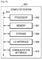
- FIG. 8 illustrates an example computer system 800.
- one or more computer systems 800 perform one or more steps of one or more methods described or illustrated herein.
- one or more computer systems 800 provide functionality described or illustrated herein.
- software running on one or more computer systems 800 performs one or more steps of one or more methods described or illustrated herein or provides functionality described or illustrated herein.
- Particular embodiments include one or more portions of one or more computer systems 800.
- reference to a computer system may encompass a computing device, and vice versa, where appropriate.
- reference to a computer system may encompass one or more computer systems, where appropriate.
- computer system 800 may be an embedded computer system, a system-on-chip (SOC), a single-board computer system (SBC) (such as, for example, a computer-on-module (COM) or system-on-module (SOM)), a desktop computer system, a laptop or notebook computer system, an interactive kiosk, a mainframe, a mesh of computer systems, a mobile telephone, a personal digital assistant (PDA), a server, a tablet computer system, an augmented/virtual reality device, or a combination of two or more of these.
- SOC system-on-chip
- SBC single-board computer system
- COM computer-on-module
- SOM system-on-module
- computer system 800 may include one or more computer systems 800; be unitary or distributed; span multiple locations; span multiple machines; span multiple data centers; or reside in a cloud, which may include one or more cloud components in one or more networks.
- one or more computer systems 800 may perform without substantial spatial or temporal limitation one or more steps of one or more methods described or illustrated herein.
- one or more computer systems 800 may perform in real time or in batch mode one or more steps of one or more methods described or illustrated herein.
- One or more computer systems 800 may perform at different times or at different locations one or more steps of one or more methods described or illustrated herein, where appropriate.
- computer system 800 includes a processor 802, memory 804, storage 806, an input/output (I/O) interface 808, a communication interface 810, and a bus 812.
- I/O input/output
- this disclosure describes and illustrates a particular computer system having a particular number of particular components in a particular arrangement, this disclosure contemplates any suitable computer system having any suitable number of any suitable components in any suitable arrangement.
- processor 802 includes hardware for executing instructions, such as those making up a computer program.
- processor 802 may retrieve (or fetch) the instructions from an internal register, an internal cache, memory 804, or storage 806; decode and execute them; and then write one or more results to an internal register, an internal cache, memory 804, or storage 806.
- processor 802 may include one or more internal caches for data, instructions, or addresses. This disclosure contemplates processor 802 including any suitable number of any suitable internal caches, where appropriate.
- processor 802 may include one or more instruction caches, one or more data caches, and one or more translation lookaside buffers (TLBs).
- TLBs translation lookaside buffers
- Instructions in the instruction caches may be copies of instructions in memory 804 or storage 806, and the instruction caches may speed up retrieval of those instructions by processor 802.
- Data in the data caches may be copies of data in memory 804 or storage 806 for instructions executing at processor 802 to operate on; the results of previous instructions executed at processor 802 for access by subsequent instructions executing at processor 802 or for writing to memory 804 or storage 806; or other suitable data.
- the data caches may speed up read or write operations by processor 802.
- the TLBs may speed up virtual-address translation for processor 802.
- processor 802 may include one or more internal registers for data, instructions, or addresses. This disclosure contemplates processor 802 including any suitable number of any suitable internal registers, where appropriate. Where appropriate, processor 802 may include one or more arithmetic logic units (ALUs); be a multi-core processor; or include one or more processors 802. Although this disclosure describes and illustrates a particular processor, this disclosure contemplates any suitable processor.
- ALUs
- memory 804 includes main memory for storing instructions for processor 802 to execute or data for processor 802 to operate on.
- computer system 800 may load instructions from storage 806 or another source (such as, for example, another computer system 800) to memory 804.
- Processor 802 may then load the instructions from memory 804 to an internal register or internal cache.
- processor 802 may retrieve the instructions from the internal register or internal cache and decode them.
- processor 802 may write one or more results (which may be intermediate or final results) to the internal register or internal cache.
- Processor 802 may then write one or more of those results to memory 804.
- processor 802 executes only instructions in one or more internal registers or internal caches or in memory 804 (as opposed to storage 806 or elsewhere) and operates only on data in one or more internal registers or internal caches or in memory 804 (as opposed to storage 806 or elsewhere).
- One or more memory buses (which may each include an address bus and a data bus) may couple processor 802 to memory 804.
- Bus 812 may include one or more memory buses, as described below.
- one or more memory management units reside between processor 802 and memory 804 and facilitate accesses to memory 804 requested by processor 802.
- memory 804 includes random access memory (RAM).
- This RAM may be volatile memory, where appropriate Where appropriate, this RAM may be dynamic RAM (DRAM) or static RAM (SRAM). Moreover, where appropriate, this RAM may be single-ported or multi-ported RAM. This disclosure contemplates any suitable RAM.
- Memory 804 may include one or more memories 804, where appropriate. Although this disclosure describes and illustrates particular memory, this disclosure contemplates any suitable memory.
- storage 806 includes mass storage for data or instructions.
- storage 806 may include a hard disk drive (HDD), a floppy disk drive, flash memory, an optical disc, a magneto-optical disc, magnetic tape, or a Universal Serial Bus (USB) drive or a combination of two or more of these.
- Storage 806 may include removable or non-removable (or fixed) media, where appropriate.
- Storage 806 may be internal or external to computer system 800, where appropriate.
- storage 806 is non-volatile, solid-state memory.
- storage 806 includes read-only memory (ROM).
- this ROM may be mask-programmed ROM, programmable ROM (PROM), erasable PROM (EPROM), electrically erasable PROM (EEPROM), electrically alterable ROM (EAROM), or flash memory or a combination of two or more of these.
- This disclosure contemplates mass storage 806 taking any suitable physical form.
- Storage 806 may include one or more storage control units facilitating communication between processor 802 and storage 806, where appropriate. Where appropriate, storage 806 may include one or more storages 806. Although this disclosure describes and illustrates particular storage, this disclosure contemplates any suitable storage.
- I/O interface 808 includes hardware, software, or both, providing one or more interfaces for communication between computer system 800 and one or more I/O devices.
- Computer system 800 may include one or more of these I/O devices, where appropriate.
- One or more of these I/O devices may enable communication between a person and computer system 800.
- an I/O device may include a keyboard, keypad, microphone, monitor, mouse, printer, scanner, speaker, still camera, stylus, tablet, touch screen, trackball, video camera, another suitable I/O device or a combination of two or more of these.
- An I/O device may include one or more sensors. This disclosure contemplates any suitable I/O devices and any suitable I/O interfaces 808 for them.
- I/ O interface 808 may include one or more device or software drivers enabling processor 802 to drive one or more of these I/O devices.
- I/O interface 808 may include one or more I/O interfaces 808, where appropriate. Although this disclosure describes and illustrates a particular I/O interface, this disclosure contemplates any suitable I/O interface.
- communication interface 810 includes hardware, software, or both providing one or more interfaces for communication (such as, for example, packet-based communication) between computer system 800 and one or more other computer systems 800 or one or more networks.
- communication interface 810 may include a network interface controller (NIC) or network adapter for communicating with an Ethernet or other wire-based network or a wireless NIC (WNIC) or wireless adapter for communicating with a wireless network, such as a WI-FI network.
- NIC network interface controller
- WNIC wireless NIC
- WI-FI network wireless network
- computer system 800 may communicate with an ad hoc network, a personal area network (PAN), a local area network (LAN), a wide area network (WAN), a metropolitan area network (MAN), or one or more portions of the Internet or a combination of two or more of these.
- PAN personal area network
- LAN local area network
- WAN wide area network
- MAN metropolitan area network
- computer system 800 may communicate with a wireless PAN (WPAN) (such as, for example, a BLUETOOTH WPAN), a WI-FI network, a WI-MAX network, a cellular telephone network (such as, for example, a Global System for Mobile Communications (GSM) network), or other suitable wireless network or a combination of two or more of these.
- Computer system 800 may include any suitable communication interface 810 for any of these networks, where appropriate.
- Communication interface 810 may include one or more communication interfaces 810, where appropriate.
- bus 812 includes hardware, software, or both coupling components of computer system 800 to each other.
- bus 812 may include an Accelerated Graphics Port (AGP) or other graphics bus, an Enhanced Industry Standard Architecture (EISA) bus, a front-side bus (FSB), a HYPERTRANSPORT (HT) interconnect, an Industry Standard Architecture (ISA) bus, an INFINIBAND interconnect, a low-pin-count (LPC) bus, a memory bus, a Micro Channel Architecture (MCA) bus, a Peripheral Component Interconnect (PCI) bus, a PCI-Express (PCIe) bus, a serial advanced technology attachment (SATA) bus, a Video Electronics Standards Association local (VLB) bus, or another suitable bus or a combination of two or more of these.
- Bus 812 may include one or more buses 812, where appropriate.
- a computer-readable non-transitory storage medium or media may include one or more semiconductor-based or other integrated circuits (ICs) (such, as for example, field-programmable gate arrays (FPGAs) or application-specific ICs (ASICs)), hard disk drives (HDDs), hybrid hard drives (HHDs), optical discs, optical disc drives (ODDs), magneto-optical discs, magneto-optical drives, floppy diskettes, floppy disk drives (FDDs), magnetic tapes, solid-state drives (SSDs), RAM-drives, SECURE DIGITAL cards or drives, any other suitable computer-readable non-transitory storage media, or any suitable combination of two or more of these, where appropriate.
- ICs such, as for example, field-programmable gate arrays (FPGAs) or application-specific ICs (ASICs)
- HDDs hard disk drives
- HHDs hybrid hard drives
- ODDs optical disc drives
- magneto-optical discs magneto-optical drives
Landscapes
- Engineering & Computer Science (AREA)
- General Engineering & Computer Science (AREA)
- Theoretical Computer Science (AREA)
- Human Computer Interaction (AREA)
- Computer Networks & Wireless Communication (AREA)
- Signal Processing (AREA)
- Physics & Mathematics (AREA)
- General Physics & Mathematics (AREA)
- Automation & Control Theory (AREA)
- User Interface Of Digital Computer (AREA)
- Alarm Systems (AREA)
Claims (14)
- Appareil (800) comprenant :un premier capteur comprenant un capteur de profondeur (160a) ;un ou plusieurs supports de stockage lisibles par ordinateur (806) comportant des instructions ; etun ou plusieurs processeurs (802) configurés pour exécuter les instructions pour :surveiller (620), au moins en partie par la sortie du capteur de profondeur, un environnement physique comprenant une zone interactive définie par l'utilisateur en vue d'un événement prédéfini ;détecter (630), au moins en partie par la sortie du capteur de profondeur, l'événement prédéfini dans la zone interactive ; eten réponse à la détection de l'événement prédéfini, lancer (640) une action prédéfinie associée à l'événement prédéfini,ledit événement prédéfini comprenant une pluralité de conditions d'événement, caractérisé en ce que l'appareil comprend un second capteur (160b) destiné à détecter une condition environnementale et en ce quela pluralité de conditions d'événement comprennent un événement déterminé à partir de la sortie du second capteur utilisé pour détecter une condition environnementale.
- Appareil selon la revendication 1, ledit ou lesdits processeurs étant en outre configurés pour exécuter les instructions pour identifier la zone d'interaction sur la base d'une entrée utilisateur.
- Appareil selon la revendication 2, ledit ou lesdits processeurs étant en outre configurés pour exécuter les instructions pour :
en réponse à la réception de l'entrée identifiant la zone interactive, allouer, sur la base au moins en partie d'une charge de surveillance, des ressources pour surveiller la zone interactive. - Appareil selon la revendication 1, l'une ou plusieurs parmi : ladite action prédéfinie étant définie au moins en partie par un utilisateur ; ou ladite association de l'action prédéfinie à l'événement prédéfini étant définie au moins en partie par l'utilisateur.
- Appareil selon la revendication 1, lesdits processeurs qui sont configurés pour exécuter les instructions pour surveiller la zone interactive en vue d'un événement prédéfini comprenant en outre des processeurs qui sont configurés pour exécuter les instructions pour :surveiller la zone interactive pour un événement seuil ; eten réponse à la détection de l'événement seuil, surveiller la zone interactive en vue de l'événement prédéfini.
- Appareil selon la revendication 1, ledit événement prédéfini comprenant l'un ou plusieurs de :une présence d'un objet ou d'un utilisateur dans la zone interactive ;un mouvement d'un objet ou d'un utilisateur dans la zone interactive ; ouun contact entre un utilisateur et au moins une partie d'un objet dans la zone interactive.
- Appareil selon la revendication 1, ledit ou lesdits processeurs étant en outre configurés pour exécuter les instructions pour surveiller périodiquement, au moins en partie par la sortie du capteur de profondeur, une pluralité de zones interactives selon une priorité associée à chaque zone interactive.
- Appareil selon la revendication 7, une première priorité associée à une première zone interactive étant basée au moins en partie sur l'un ou plusieurs parmi :des données d'événement historiques associées à la première zone interactive ;une fréquence attendue d'un ou plusieurs événements prédéfinis dans la première zone interactive ;une durée attendue d'un ou plusieurs événements prédéfinis dans la première zone interactive ; ouune importance de la première zone interactive.
- Appareil selon la revendication 1, ledit ou lesdits processeurs étant en outre configurés pour exécuter les instructions pour surveiller, au moins en partie par le capteur de profondeur, un environnement physique comprenant une zone interactive définie par l'utilisateur pour chacun d'une pluralité d'événements prédéfinis selon une priorité associée à chaque événement.
- Appareil selon la revendication 1,
ladite zone interactive comprenant une première zone interactive ;
au moins une partie de la première zone interactive comprenant au moins une partie d'une seconde zone interactive associée à un ou plusieurs événements prédéfinis de seconde zone ; et
lesdits processeurs étant en outre configurés pour exécuter les instructions pour détecter, sur la base de données créées en surveillant la partie de la première zone interactive, un ou plusieurs événements prédéfinis de seconde zone dans la partie de la seconde zone interactive. - Procédé (600) comprenant :la surveillance (620), au moins en partie par une sortie d'un premier capteur comprenant un capteur de profondeur (160), d'un environnement physique comprenant une zone interactive définie par l'utilisateur en vue d'un événement prédéfini ;la détection (630), au moins en partie par la sortie du capteur de profondeur, de l'événement prédéfini dans la zone interactive ; eten réponse à la détection de l'événement prédéfini, le lancement automatique (640) d'une action prédéfinie associée à l'événement prédéfini,ledit événement prédéfini comprenant une pluralité de conditions d'événement, caractérisé en ce quela pluralité de conditions d'événement comprennent un événement déterminé à partir de la sortie d'un second capteur, ledit second capteur étant utilisé pour détecter une condition environnementale.
- Procédé selon la revendication 11, comprenant en outre l'identification de la zone interactive sur la base d'une entrée utilisateur.
- Procédé selon la revendication 11, l'une ou plusieurs parmi :ladite action prédéfinie étant définie au moins en partie par un utilisateur ; ouladite association de l'action prédéfinie à l'événement prédéfini étant définie au moins en partie par l'utilisateur.
- Support(s) de stockage lisible(s) par ordinateur comportant des instructions qui, lorsqu'elles sont exécutées par un ou plusieurs processeurs, amènent le ou les processeurs à réaliser un procédé selon l'une quelconque des revendications 11 à 13.
Applications Claiming Priority (4)
| Application Number | Priority Date | Filing Date | Title |
|---|---|---|---|
| US201562208265P | 2015-08-21 | 2015-08-21 | |
| US15/015,040 US10057078B2 (en) | 2015-08-21 | 2016-02-03 | User-configurable interactive region monitoring |
| KR1020160104498A KR20170022912A (ko) | 2015-08-21 | 2016-08-17 | 사용자 설정가능 인터랙티브 영역 모니터링 장치 및 방법 |
| PCT/KR2016/009097 WO2017034217A1 (fr) | 2015-08-21 | 2016-08-18 | Appareil et procédé de surveillance de région interactive configurable par l'utilisateur |
Publications (3)
| Publication Number | Publication Date |
|---|---|
| EP3338433A1 EP3338433A1 (fr) | 2018-06-27 |
| EP3338433A4 EP3338433A4 (fr) | 2018-08-29 |
| EP3338433B1 true EP3338433B1 (fr) | 2020-11-11 |
Family
ID=58158081
Family Applications (1)
| Application Number | Title | Priority Date | Filing Date |
|---|---|---|---|
| EP16839506.9A Active EP3338433B1 (fr) | 2015-08-21 | 2016-08-18 | Appareil et procédé de surveillance de région interactive configurable par l'utilisateur |
Country Status (4)
| Country | Link |
|---|---|
| US (2) | US10057078B2 (fr) |
| EP (1) | EP3338433B1 (fr) |
| KR (1) | KR20170022912A (fr) |
| CN (1) | CN108353089B (fr) |
Families Citing this family (30)
| Publication number | Priority date | Publication date | Assignee | Title |
|---|---|---|---|---|
| US10600249B2 (en) | 2015-10-16 | 2020-03-24 | Youar Inc. | Augmented reality platform |
| WO2017147403A1 (fr) | 2016-02-24 | 2017-08-31 | Preaction Technology Corporation, dba/4c Sports Corporation | Procédé et système de détermination de l'état physiologique d'utilisateurs en se basant sur la capture de mouvement sans marqueur |
| US10802695B2 (en) * | 2016-03-23 | 2020-10-13 | Youar Inc. | Augmented reality for the internet of things |
| CN107346172B (zh) * | 2016-05-05 | 2022-08-30 | 富泰华工业(深圳)有限公司 | 一种动作感应方法及装置 |
| JP6232632B1 (ja) * | 2016-08-09 | 2017-11-22 | パロニム株式会社 | 動画再生プログラム、動画再生装置、動画再生方法、動画配信システム及びメタデータ作成方法 |
| KR102432283B1 (ko) | 2017-05-01 | 2022-08-11 | 매직 립, 인코포레이티드 | 콘텐츠를 공간 3d 환경에 매칭 |
| CN119919611A (zh) * | 2017-12-22 | 2025-05-02 | 奇跃公司 | 用于在混合现实系统中管理和显示虚拟内容的方法和系统 |
| WO2019165055A1 (fr) | 2018-02-22 | 2019-08-29 | Magic Leap, Inc. | Navigateur pour systèmes de réalité mixte |
| KR102836545B1 (ko) | 2018-02-22 | 2025-07-18 | 매직 립, 인코포레이티드 | 물리적 조작을 사용한 오브젝트 생성 |
| KR102524586B1 (ko) * | 2018-04-30 | 2023-04-21 | 삼성전자주식회사 | 전자 장치 및 그 동작방법 |
| US11288733B2 (en) * | 2018-11-14 | 2022-03-29 | Mastercard International Incorporated | Interactive 3D image projection systems and methods |
| EP3671261A1 (fr) * | 2018-12-21 | 2020-06-24 | Leica Geosystems AG | Système de surveillance 3d comprenant un lidar et imagerie multispectrale de classification d'objets |
| CN109803013B (zh) * | 2019-01-21 | 2020-10-23 | 浙江大学 | 一种基于人工智能的弱交互系统及其控制方法 |
| EP3712852B1 (fr) * | 2019-03-19 | 2021-12-15 | Carrier Corporation | Armoire de vente réfrigérée |
| CN110109364A (zh) * | 2019-03-25 | 2019-08-09 | 深圳绿米联创科技有限公司 | 设备控制方法、装置、摄像机以及存储介质 |
| WO2020206313A1 (fr) | 2019-04-03 | 2020-10-08 | Magic Leap, Inc. | Gestion et affichage de pages web dans un espace tridimensionnel virtuel à l'aide d'un système de réalité mixte |
| US10890983B2 (en) | 2019-06-07 | 2021-01-12 | Facebook Technologies, Llc | Artificial reality system having a sliding menu |
| US11334212B2 (en) | 2019-06-07 | 2022-05-17 | Facebook Technologies, Llc | Detecting input in artificial reality systems based on a pinch and pull gesture |
| US11351682B2 (en) * | 2019-06-19 | 2022-06-07 | International Business Machines Corporation | Environment monitoring and associated monitoring device |
| CN110248235B (zh) * | 2019-06-26 | 2022-06-17 | 深圳市轱辘车联数据技术有限公司 | 软件教学方法、装置、终端设备及介质 |
| DE102019214198A1 (de) * | 2019-09-18 | 2021-03-18 | Robert Bosch Gmbh | Ereignisbasierte Erkennung und Verfolgung von Objekten |
| US10991163B2 (en) * | 2019-09-20 | 2021-04-27 | Facebook Technologies, Llc | Projection casting in virtual environments |
| US11189099B2 (en) | 2019-09-20 | 2021-11-30 | Facebook Technologies, Llc | Global and local mode virtual object interactions |
| CN111649729A (zh) * | 2020-05-16 | 2020-09-11 | 阿勒泰正元国际矿业有限公司 | 一种基于三维激光扫描的矿山采空区探测方法 |
| WO2022170105A1 (fr) * | 2021-02-05 | 2022-08-11 | Pepsico, Inc. | Dispositifs, systèmes et procédés d'interfaçage sans contact |
| CN114091601B (zh) * | 2021-11-18 | 2023-05-05 | 业成科技(成都)有限公司 | 人员状况侦测的传感器融合方法 |
| US11726578B1 (en) | 2022-02-11 | 2023-08-15 | Meta Platforms Technologies, Llc | Scrolling and navigation in virtual reality |
| US12400414B2 (en) | 2023-02-08 | 2025-08-26 | Meta Platforms Technologies, Llc | Facilitating system user interface (UI) interactions in an artificial reality (XR) environment |
| US12387449B1 (en) | 2023-02-08 | 2025-08-12 | Meta Platforms Technologies, Llc | Facilitating system user interface (UI) interactions in an artificial reality (XR) environment |
| US11991222B1 (en) | 2023-05-02 | 2024-05-21 | Meta Platforms Technologies, Llc | Persistent call control user interface element in an artificial reality environment |
Family Cites Families (48)
| Publication number | Priority date | Publication date | Assignee | Title |
|---|---|---|---|---|
| US7680295B2 (en) | 2001-09-17 | 2010-03-16 | National Institute Of Advanced Industrial Science And Technology | Hand-gesture based interface apparatus |
| JP2006507641A (ja) | 2002-11-22 | 2006-03-02 | コーニンクレッカ フィリップス エレクトロニクス エヌ ヴィ | 光源を制御するシステム及び方法と照明配置 |
| JP4035610B2 (ja) | 2002-12-18 | 2008-01-23 | 独立行政法人産業技術総合研究所 | インタフェース装置 |
| US7610280B2 (en) | 2005-05-05 | 2009-10-27 | Cisco Technology, Inc. | Method and system for dynamically pre-positioning content in a network based detecting or predicting user presence |
| US8180114B2 (en) | 2006-07-13 | 2012-05-15 | Northrop Grumman Systems Corporation | Gesture recognition interface system with vertical display |
| KR101141087B1 (ko) * | 2007-09-14 | 2012-07-12 | 인텔렉츄얼 벤처스 홀딩 67 엘엘씨 | 제스처-기반 사용자 상호작용의 프로세싱 |
| FR2928809B1 (fr) | 2008-03-17 | 2012-06-29 | Antoine Doublet | Systeme interactif et procede de commande d'eclairages et/ou de diffusion d'images |
| US8594467B2 (en) * | 2008-12-19 | 2013-11-26 | Microsoft Corporation | Interactive virtual display system for ubiquitous devices |
| WO2010096191A2 (fr) * | 2009-02-18 | 2010-08-26 | Exbiblio B.V. | Informations de capture automatique telles que des informations de capture utilisant un dispositif prenant en charge des documents |
| US8693724B2 (en) | 2009-05-29 | 2014-04-08 | Microsoft Corporation | Method and system implementing user-centric gesture control |
| US8487888B2 (en) | 2009-12-04 | 2013-07-16 | Microsoft Corporation | Multi-modal interaction on multi-touch display |
| US8396888B2 (en) * | 2009-12-04 | 2013-03-12 | Google Inc. | Location-based searching using a search area that corresponds to a geographical location of a computing device |
| CN102918476B (zh) * | 2010-02-05 | 2017-03-08 | 索尼电脑娱乐公司 | 用于利用位置、方向或动作与计算程序相接口的控制器 |
| US8659658B2 (en) | 2010-02-09 | 2014-02-25 | Microsoft Corporation | Physical interaction zone for gesture-based user interfaces |
| US8499257B2 (en) | 2010-02-09 | 2013-07-30 | Microsoft Corporation | Handles interactions for human—computer interface |
| US8351651B2 (en) | 2010-04-26 | 2013-01-08 | Microsoft Corporation | Hand-location post-process refinement in a tracking system |
| WO2012014498A1 (fr) | 2010-07-30 | 2012-02-02 | 三洋電機株式会社 | Dispositif sans fil |
| WO2012121433A1 (fr) * | 2011-03-09 | 2012-09-13 | Lg Electronics Inc. | Dispositif d'affichage et procédé de commande correspondant |
| US8929612B2 (en) * | 2011-06-06 | 2015-01-06 | Microsoft Corporation | System for recognizing an open or closed hand |
| US20120322380A1 (en) * | 2011-06-16 | 2012-12-20 | Owen Nannarone | Localized tracking of items with electronic labels |
| US9844344B2 (en) * | 2011-07-05 | 2017-12-19 | Saudi Arabian Oil Company | Systems and method to monitor health of employee when positioned in association with a workstation |
| US8558759B1 (en) | 2011-07-08 | 2013-10-15 | Google Inc. | Hand gestures to signify what is important |
| US9002099B2 (en) | 2011-09-11 | 2015-04-07 | Apple Inc. | Learning-based estimation of hand and finger pose |
| US20130083003A1 (en) * | 2011-09-30 | 2013-04-04 | Kathryn Stone Perez | Personal audio/visual system |
| US20150012426A1 (en) * | 2013-01-04 | 2015-01-08 | Visa International Service Association | Multi disparate gesture actions and transactions apparatuses, methods and systems |
| US8854433B1 (en) | 2012-02-03 | 2014-10-07 | Aquifi, Inc. | Method and system enabling natural user interface gestures with an electronic system |
| CN102789313B (zh) * | 2012-03-19 | 2015-05-13 | 苏州触达信息技术有限公司 | 一种用户交互系统和方法 |
| US9293016B2 (en) * | 2012-04-24 | 2016-03-22 | At&T Intellectual Property I, Lp | Method and apparatus for processing sensor data of detected objects |
| US9619036B2 (en) | 2012-05-11 | 2017-04-11 | Comcast Cable Communications, Llc | System and methods for controlling a user experience |
| JP6210979B2 (ja) * | 2012-05-24 | 2017-10-11 | 株式会社 ジャパン・ティッシュ・エンジニアリング | 細胞含有物用容器及び細胞含有物収容済み容器 |
| US8837780B2 (en) | 2012-06-22 | 2014-09-16 | Hewlett-Packard Development Company, L.P. | Gesture based human interfaces |
| WO2014015562A1 (fr) * | 2012-07-23 | 2014-01-30 | Liu Liang | Dispositif et système de transmission d'informations |
| JP6019947B2 (ja) | 2012-08-31 | 2016-11-02 | オムロン株式会社 | ジェスチャ認識装置、その制御方法、表示機器、および制御プログラム |
| CN102945362B (zh) * | 2012-10-18 | 2016-01-27 | 中国科学院计算技术研究所 | 基于异构数据融合的传感器协同手势识别方法及系统 |
| US9264478B2 (en) * | 2012-10-30 | 2016-02-16 | Microsoft Technology Licensing, Llc | Home cloud with virtualized input and output roaming over network |
| US9135710B2 (en) * | 2012-11-30 | 2015-09-15 | Adobe Systems Incorporated | Depth map stereo correspondence techniques |
| US9916009B2 (en) | 2013-04-26 | 2018-03-13 | Leap Motion, Inc. | Non-tactile interface systems and methods |
| US9465488B2 (en) | 2013-05-09 | 2016-10-11 | Stephen Howard | System and method for motion detection and interpretation |
| US9348421B2 (en) * | 2013-06-26 | 2016-05-24 | Float Hybrid Entertainment Inc. | Gesture and touch-based interactivity with objects using 3D zones in an interactive system |
| EP3092806A4 (fr) * | 2014-01-07 | 2017-08-23 | Nokia Technologies Oy | Procédé et appareil de codage et de décodage vidéo |
| US9872362B2 (en) * | 2014-01-30 | 2018-01-16 | Philips Lighting Holding B.V. | Gesture based control of a utility |
| WO2015117852A1 (fr) * | 2014-02-07 | 2015-08-13 | Koninklijke Philips N.V. | Procédé de fonctionnement d'un système de commande et système de commande associé |
| US9916010B2 (en) * | 2014-05-16 | 2018-03-13 | Visa International Service Association | Gesture recognition cloud command platform, system, method, and apparatus |
| US10068373B2 (en) * | 2014-07-01 | 2018-09-04 | Samsung Electronics Co., Ltd. | Electronic device for providing map information |
| WO2016009016A1 (fr) * | 2014-07-17 | 2016-01-21 | Koninklijke Philips N.V. | Procédé d'obtention des données de définition de zone gestuelle pour un système de commande à base d'entrée utilisateur |
| US9363569B1 (en) * | 2014-07-28 | 2016-06-07 | Jaunt Inc. | Virtual reality system including social graph |
| US9693375B2 (en) * | 2014-11-24 | 2017-06-27 | Apple Inc. | Point-to-point ad hoc voice communication |
| US9811165B2 (en) * | 2015-03-11 | 2017-11-07 | Samsung Electronics Co., Ltd. | Electronic system with gesture processing mechanism and method of operation thereof |
-
2016
- 2016-02-03 US US15/015,040 patent/US10057078B2/en active Active
- 2016-08-17 KR KR1020160104498A patent/KR20170022912A/ko not_active Ceased
- 2016-08-18 EP EP16839506.9A patent/EP3338433B1/fr active Active
- 2016-08-18 CN CN201680048423.8A patent/CN108353089B/zh not_active Expired - Fee Related
-
2018
- 2018-07-19 US US16/040,438 patent/US10298412B2/en active Active
Non-Patent Citations (1)
| Title |
|---|
| None * |
Also Published As
| Publication number | Publication date |
|---|---|
| US10057078B2 (en) | 2018-08-21 |
| US20170054569A1 (en) | 2017-02-23 |
| CN108353089B (zh) | 2021-05-28 |
| US10298412B2 (en) | 2019-05-21 |
| EP3338433A1 (fr) | 2018-06-27 |
| CN108353089A (zh) | 2018-07-31 |
| US20180323992A1 (en) | 2018-11-08 |
| KR20170022912A (ko) | 2017-03-02 |
| EP3338433A4 (fr) | 2018-08-29 |
Similar Documents
| Publication | Publication Date | Title |
|---|---|---|
| US10298412B2 (en) | User-configurable interactive region monitoring | |
| US10796185B2 (en) | Dynamic graceful degradation of augmented-reality effects | |
| US20220004766A1 (en) | Systems and methods for detecting objects within the boundary of a defined space while in artificial reality | |
| CN107113544B (zh) | 用于物联网设备的3d映射的方法、系统及介质 | |
| US9639984B2 (en) | Data manipulation based on real world object manipulation | |
| US9898844B2 (en) | Augmented reality content adapted to changes in real world space geometry | |
| KR20230098172A (ko) | 확장 현실 시스템들을 위한 추천들 | |
| US20150185825A1 (en) | Assigning a virtual user interface to a physical object | |
| US20150187137A1 (en) | Physical object discovery | |
| KR20240049534A (ko) | 사용자 설정가능 인터랙티브 영역 모니터링 장치 및 방법 | |
| TW202025800A (zh) | 用於物聯網設備消歧的系統和方法 | |
| US20150185826A1 (en) | Mapping gestures to virtual functions | |
| KR20220159347A (ko) | 인공 현실에 있는 동안 침입을 검출하기 위한 시스템 및 방법 | |
| US20160266648A1 (en) | Systems and methods for interacting with large displays using shadows | |
| US20180268607A1 (en) | Data manipulation based on real world object manipulation | |
| KR20250115959A (ko) | 사용자 설정가능 인터랙티브 영역 모니터링 장치 및 방법 | |
| CN111902849B (zh) | 在图像上叠加传感器及其检测区域的虚拟表示 | |
| EP3480789B1 (fr) | Dégradation progressive dynamique d'effets de réalité augmentée | |
| US12277260B1 (en) | Automatically adjusting display-screen pose | |
| KR20260033075A (ko) | 환경들의 표현들 관리 | |
| Von Dehsen | Camera Lens with Display Mode | |
| Benassi | Systems and Methods for Adjusting Lighting to Improve Image Quality | |
| Von Dehsen | Providing a Camera Stream on an Ancillary Display | |
| HK1197944A (en) | Augmented reality display of scene behind surface | |
| HK1197944B (en) | Augmented reality display of scene behind surface |
Legal Events
| Date | Code | Title | Description |
|---|---|---|---|
| STAA | Information on the status of an ep patent application or granted ep patent |
Free format text: STATUS: THE INTERNATIONAL PUBLICATION HAS BEEN MADE |
|
| PUAI | Public reference made under article 153(3) epc to a published international application that has entered the european phase |
Free format text: ORIGINAL CODE: 0009012 |
|
| STAA | Information on the status of an ep patent application or granted ep patent |
Free format text: STATUS: REQUEST FOR EXAMINATION WAS MADE |
|
| 17P | Request for examination filed |
Effective date: 20180213 |
|
| AK | Designated contracting states |
Kind code of ref document: A1 Designated state(s): AL AT BE BG CH CY CZ DE DK EE ES FI FR GB GR HR HU IE IS IT LI LT LU LV MC MK MT NL NO PL PT RO RS SE SI SK SM TR |
|
| AX | Request for extension of the european patent |
Extension state: BA ME |
|
| A4 | Supplementary search report drawn up and despatched |
Effective date: 20180730 |
|
| RIC1 | Information provided on ipc code assigned before grant |
Ipc: H04W 4/021 20180101ALI20180724BHEP Ipc: H04W 4/33 20180101ALI20180724BHEP Ipc: H04L 12/28 20060101AFI20180724BHEP |
|
| DAV | Request for validation of the european patent (deleted) | ||
| DAX | Request for extension of the european patent (deleted) | ||
| STAA | Information on the status of an ep patent application or granted ep patent |
Free format text: STATUS: EXAMINATION IS IN PROGRESS |
|
| 17Q | First examination report despatched |
Effective date: 20200115 |
|
| REG | Reference to a national code |
Ref country code: DE Ref legal event code: R079 Ref document number: 602016047811 Country of ref document: DE Free format text: PREVIOUS MAIN CLASS: H04L0029080000 Ipc: H04L0012280000 |
|
| RIC1 | Information provided on ipc code assigned before grant |
Ipc: H04L 12/28 20060101AFI20200528BHEP Ipc: G06K 9/00 20060101ALN20200528BHEP Ipc: H04W 4/33 20180101ALI20200528BHEP Ipc: H04W 4/021 20180101ALI20200528BHEP Ipc: G06F 3/01 20060101ALI20200528BHEP |
|
| GRAP | Despatch of communication of intention to grant a patent |
Free format text: ORIGINAL CODE: EPIDOSNIGR1 |
|
| STAA | Information on the status of an ep patent application or granted ep patent |
Free format text: STATUS: GRANT OF PATENT IS INTENDED |
|
| INTG | Intention to grant announced |
Effective date: 20200721 |
|
| GRAS | Grant fee paid |
Free format text: ORIGINAL CODE: EPIDOSNIGR3 |
|
| GRAA | (expected) grant |
Free format text: ORIGINAL CODE: 0009210 |
|
| STAA | Information on the status of an ep patent application or granted ep patent |
Free format text: STATUS: THE PATENT HAS BEEN GRANTED |
|
| AK | Designated contracting states |
Kind code of ref document: B1 Designated state(s): AL AT BE BG CH CY CZ DE DK EE ES FI FR GB GR HR HU IE IS IT LI LT LU LV MC MK MT NL NO PL PT RO RS SE SI SK SM TR |
|
| REG | Reference to a national code |
Ref country code: GB Ref legal event code: FG4D |
|
| REG | Reference to a national code |
Ref country code: CH Ref legal event code: EP |
|
| REG | Reference to a national code |
Ref country code: AT Ref legal event code: REF Ref document number: 1334499 Country of ref document: AT Kind code of ref document: T Effective date: 20201115 |
|
| REG | Reference to a national code |
Ref country code: DE Ref legal event code: R096 Ref document number: 602016047811 Country of ref document: DE |
|
| REG | Reference to a national code |
Ref country code: IE Ref legal event code: FG4D |
|
| REG | Reference to a national code |
Ref country code: NL Ref legal event code: MP Effective date: 20201111 |
|
| REG | Reference to a national code |
Ref country code: AT Ref legal event code: MK05 Ref document number: 1334499 Country of ref document: AT Kind code of ref document: T Effective date: 20201111 |
|
| PG25 | Lapsed in a contracting state [announced via postgrant information from national office to epo] |
Ref country code: RS Free format text: LAPSE BECAUSE OF FAILURE TO SUBMIT A TRANSLATION OF THE DESCRIPTION OR TO PAY THE FEE WITHIN THE PRESCRIBED TIME-LIMIT Effective date: 20201111 Ref country code: PT Free format text: LAPSE BECAUSE OF FAILURE TO SUBMIT A TRANSLATION OF THE DESCRIPTION OR TO PAY THE FEE WITHIN THE PRESCRIBED TIME-LIMIT Effective date: 20210311 Ref country code: NO Free format text: LAPSE BECAUSE OF FAILURE TO SUBMIT A TRANSLATION OF THE DESCRIPTION OR TO PAY THE FEE WITHIN THE PRESCRIBED TIME-LIMIT Effective date: 20210211 Ref country code: FI Free format text: LAPSE BECAUSE OF FAILURE TO SUBMIT A TRANSLATION OF THE DESCRIPTION OR TO PAY THE FEE WITHIN THE PRESCRIBED TIME-LIMIT Effective date: 20201111 Ref country code: GR Free format text: LAPSE BECAUSE OF FAILURE TO SUBMIT A TRANSLATION OF THE DESCRIPTION OR TO PAY THE FEE WITHIN THE PRESCRIBED TIME-LIMIT Effective date: 20210212 |
|
| PG25 | Lapsed in a contracting state [announced via postgrant information from national office to epo] |
Ref country code: SE Free format text: LAPSE BECAUSE OF FAILURE TO SUBMIT A TRANSLATION OF THE DESCRIPTION OR TO PAY THE FEE WITHIN THE PRESCRIBED TIME-LIMIT Effective date: 20201111 Ref country code: BG Free format text: LAPSE BECAUSE OF FAILURE TO SUBMIT A TRANSLATION OF THE DESCRIPTION OR TO PAY THE FEE WITHIN THE PRESCRIBED TIME-LIMIT Effective date: 20210211 Ref country code: IS Free format text: LAPSE BECAUSE OF FAILURE TO SUBMIT A TRANSLATION OF THE DESCRIPTION OR TO PAY THE FEE WITHIN THE PRESCRIBED TIME-LIMIT Effective date: 20210311 Ref country code: LV Free format text: LAPSE BECAUSE OF FAILURE TO SUBMIT A TRANSLATION OF THE DESCRIPTION OR TO PAY THE FEE WITHIN THE PRESCRIBED TIME-LIMIT Effective date: 20201111 Ref country code: PL Free format text: LAPSE BECAUSE OF FAILURE TO SUBMIT A TRANSLATION OF THE DESCRIPTION OR TO PAY THE FEE WITHIN THE PRESCRIBED TIME-LIMIT Effective date: 20201111 Ref country code: AT Free format text: LAPSE BECAUSE OF FAILURE TO SUBMIT A TRANSLATION OF THE DESCRIPTION OR TO PAY THE FEE WITHIN THE PRESCRIBED TIME-LIMIT Effective date: 20201111 |
|
| REG | Reference to a national code |
Ref country code: LT Ref legal event code: MG9D |
|
| PG25 | Lapsed in a contracting state [announced via postgrant information from national office to epo] |
Ref country code: HR Free format text: LAPSE BECAUSE OF FAILURE TO SUBMIT A TRANSLATION OF THE DESCRIPTION OR TO PAY THE FEE WITHIN THE PRESCRIBED TIME-LIMIT Effective date: 20201111 |
|
| PG25 | Lapsed in a contracting state [announced via postgrant information from national office to epo] |
Ref country code: SM Free format text: LAPSE BECAUSE OF FAILURE TO SUBMIT A TRANSLATION OF THE DESCRIPTION OR TO PAY THE FEE WITHIN THE PRESCRIBED TIME-LIMIT Effective date: 20201111 Ref country code: LT Free format text: LAPSE BECAUSE OF FAILURE TO SUBMIT A TRANSLATION OF THE DESCRIPTION OR TO PAY THE FEE WITHIN THE PRESCRIBED TIME-LIMIT Effective date: 20201111 Ref country code: CZ Free format text: LAPSE BECAUSE OF FAILURE TO SUBMIT A TRANSLATION OF THE DESCRIPTION OR TO PAY THE FEE WITHIN THE PRESCRIBED TIME-LIMIT Effective date: 20201111 Ref country code: EE Free format text: LAPSE BECAUSE OF FAILURE TO SUBMIT A TRANSLATION OF THE DESCRIPTION OR TO PAY THE FEE WITHIN THE PRESCRIBED TIME-LIMIT Effective date: 20201111 Ref country code: SK Free format text: LAPSE BECAUSE OF FAILURE TO SUBMIT A TRANSLATION OF THE DESCRIPTION OR TO PAY THE FEE WITHIN THE PRESCRIBED TIME-LIMIT Effective date: 20201111 Ref country code: RO Free format text: LAPSE BECAUSE OF FAILURE TO SUBMIT A TRANSLATION OF THE DESCRIPTION OR TO PAY THE FEE WITHIN THE PRESCRIBED TIME-LIMIT Effective date: 20201111 |
|
| REG | Reference to a national code |
Ref country code: DE Ref legal event code: R097 Ref document number: 602016047811 Country of ref document: DE |
|
| PG25 | Lapsed in a contracting state [announced via postgrant information from national office to epo] |
Ref country code: DK Free format text: LAPSE BECAUSE OF FAILURE TO SUBMIT A TRANSLATION OF THE DESCRIPTION OR TO PAY THE FEE WITHIN THE PRESCRIBED TIME-LIMIT Effective date: 20201111 |
|
| PLBE | No opposition filed within time limit |
Free format text: ORIGINAL CODE: 0009261 |
|
| STAA | Information on the status of an ep patent application or granted ep patent |
Free format text: STATUS: NO OPPOSITION FILED WITHIN TIME LIMIT |
|
| 26N | No opposition filed |
Effective date: 20210812 |
|
| PG25 | Lapsed in a contracting state [announced via postgrant information from national office to epo] |
Ref country code: IT Free format text: LAPSE BECAUSE OF FAILURE TO SUBMIT A TRANSLATION OF THE DESCRIPTION OR TO PAY THE FEE WITHIN THE PRESCRIBED TIME-LIMIT Effective date: 20201111 Ref country code: AL Free format text: LAPSE BECAUSE OF FAILURE TO SUBMIT A TRANSLATION OF THE DESCRIPTION OR TO PAY THE FEE WITHIN THE PRESCRIBED TIME-LIMIT Effective date: 20201111 Ref country code: NL Free format text: LAPSE BECAUSE OF FAILURE TO SUBMIT A TRANSLATION OF THE DESCRIPTION OR TO PAY THE FEE WITHIN THE PRESCRIBED TIME-LIMIT Effective date: 20201111 |
|
| PG25 | Lapsed in a contracting state [announced via postgrant information from national office to epo] |
Ref country code: SI Free format text: LAPSE BECAUSE OF FAILURE TO SUBMIT A TRANSLATION OF THE DESCRIPTION OR TO PAY THE FEE WITHIN THE PRESCRIBED TIME-LIMIT Effective date: 20201111 |
|
| PG25 | Lapsed in a contracting state [announced via postgrant information from national office to epo] |
Ref country code: ES Free format text: LAPSE BECAUSE OF FAILURE TO SUBMIT A TRANSLATION OF THE DESCRIPTION OR TO PAY THE FEE WITHIN THE PRESCRIBED TIME-LIMIT Effective date: 20201111 |
|
| REG | Reference to a national code |
Ref country code: CH Ref legal event code: PL |
|
| PG25 | Lapsed in a contracting state [announced via postgrant information from national office to epo] |
Ref country code: MC Free format text: LAPSE BECAUSE OF FAILURE TO SUBMIT A TRANSLATION OF THE DESCRIPTION OR TO PAY THE FEE WITHIN THE PRESCRIBED TIME-LIMIT Effective date: 20201111 |
|
| REG | Reference to a national code |
Ref country code: BE Ref legal event code: MM Effective date: 20210831 |
|
| PG25 | Lapsed in a contracting state [announced via postgrant information from national office to epo] |
Ref country code: LI Free format text: LAPSE BECAUSE OF NON-PAYMENT OF DUE FEES Effective date: 20210831 Ref country code: CH Free format text: LAPSE BECAUSE OF NON-PAYMENT OF DUE FEES Effective date: 20210831 |
|
| PG25 | Lapsed in a contracting state [announced via postgrant information from national office to epo] |
Ref country code: IS Free format text: LAPSE BECAUSE OF FAILURE TO SUBMIT A TRANSLATION OF THE DESCRIPTION OR TO PAY THE FEE WITHIN THE PRESCRIBED TIME-LIMIT Effective date: 20210311 Ref country code: LU Free format text: LAPSE BECAUSE OF NON-PAYMENT OF DUE FEES Effective date: 20210818 |
|
| PG25 | Lapsed in a contracting state [announced via postgrant information from national office to epo] |
Ref country code: IE Free format text: LAPSE BECAUSE OF NON-PAYMENT OF DUE FEES Effective date: 20210818 Ref country code: FR Free format text: LAPSE BECAUSE OF NON-PAYMENT OF DUE FEES Effective date: 20210831 Ref country code: BE Free format text: LAPSE BECAUSE OF NON-PAYMENT OF DUE FEES Effective date: 20210831 |
|
| PG25 | Lapsed in a contracting state [announced via postgrant information from national office to epo] |
Ref country code: HU Free format text: LAPSE BECAUSE OF FAILURE TO SUBMIT A TRANSLATION OF THE DESCRIPTION OR TO PAY THE FEE WITHIN THE PRESCRIBED TIME-LIMIT; INVALID AB INITIO Effective date: 20160818 |
|
| PG25 | Lapsed in a contracting state [announced via postgrant information from national office to epo] |
Ref country code: CY Free format text: LAPSE BECAUSE OF FAILURE TO SUBMIT A TRANSLATION OF THE DESCRIPTION OR TO PAY THE FEE WITHIN THE PRESCRIBED TIME-LIMIT Effective date: 20201111 |
|
| PG25 | Lapsed in a contracting state [announced via postgrant information from national office to epo] |
Ref country code: MK Free format text: LAPSE BECAUSE OF FAILURE TO SUBMIT A TRANSLATION OF THE DESCRIPTION OR TO PAY THE FEE WITHIN THE PRESCRIBED TIME-LIMIT Effective date: 20201111 |
|
| PG25 | Lapsed in a contracting state [announced via postgrant information from national office to epo] |
Ref country code: TR Free format text: LAPSE BECAUSE OF FAILURE TO SUBMIT A TRANSLATION OF THE DESCRIPTION OR TO PAY THE FEE WITHIN THE PRESCRIBED TIME-LIMIT Effective date: 20201111 |
|
| PG25 | Lapsed in a contracting state [announced via postgrant information from national office to epo] |
Ref country code: MT Free format text: LAPSE BECAUSE OF FAILURE TO SUBMIT A TRANSLATION OF THE DESCRIPTION OR TO PAY THE FEE WITHIN THE PRESCRIBED TIME-LIMIT Effective date: 20201111 |
|
| PGFP | Annual fee paid to national office [announced via postgrant information from national office to epo] |
Ref country code: DE Payment date: 20250721 Year of fee payment: 10 |
|
| PGFP | Annual fee paid to national office [announced via postgrant information from national office to epo] |
Ref country code: GB Payment date: 20250722 Year of fee payment: 10 |