EP3338530A1 - Antriebssystem für gartenwerkzeug mit automatischer gehfunktion - Google Patents
Antriebssystem für gartenwerkzeug mit automatischer gehfunktion Download PDFInfo
- Publication number
- EP3338530A1 EP3338530A1 EP16836395.0A EP16836395A EP3338530A1 EP 3338530 A1 EP3338530 A1 EP 3338530A1 EP 16836395 A EP16836395 A EP 16836395A EP 3338530 A1 EP3338530 A1 EP 3338530A1
- Authority
- EP
- European Patent Office
- Prior art keywords
- power system
- garden tool
- transmission shaft
- walking function
- automatic walking
- Prior art date
- Legal status (The legal status is an assumption and is not a legal conclusion. Google has not performed a legal analysis and makes no representation as to the accuracy of the status listed.)
- Granted
Links
Images

Classifications
-
- A—HUMAN NECESSITIES
- A01—AGRICULTURE; FORESTRY; ANIMAL HUSBANDRY; HUNTING; TRAPPING; FISHING
- A01D—HARVESTING; MOWING
- A01D69/00—Driving mechanisms or parts thereof for harvesters or mowers
- A01D69/06—Gearings
-
- A—HUMAN NECESSITIES
- A01—AGRICULTURE; FORESTRY; ANIMAL HUSBANDRY; HUNTING; TRAPPING; FISHING
- A01D—HARVESTING; MOWING
- A01D34/00—Mowers; Mowing apparatus of harvesters
- A01D34/01—Mowers; Mowing apparatus of harvesters characterised by features relating to the type of cutting apparatus
- A01D34/412—Mowers; Mowing apparatus of harvesters characterised by features relating to the type of cutting apparatus having rotating cutters
- A01D34/63—Mowers; Mowing apparatus of harvesters characterised by features relating to the type of cutting apparatus having rotating cutters having cutters rotating about a vertical axis
- A01D34/67—Mowers; Mowing apparatus of harvesters characterised by features relating to the type of cutting apparatus having rotating cutters having cutters rotating about a vertical axis hand-guided by a walking operator
- A01D34/68—Mowers; Mowing apparatus of harvesters characterised by features relating to the type of cutting apparatus having rotating cutters having cutters rotating about a vertical axis hand-guided by a walking operator with motor driven cutters or wheels
-
- A—HUMAN NECESSITIES
- A01—AGRICULTURE; FORESTRY; ANIMAL HUSBANDRY; HUNTING; TRAPPING; FISHING
- A01D—HARVESTING; MOWING
- A01D34/00—Mowers; Mowing apparatus of harvesters
- A01D34/01—Mowers; Mowing apparatus of harvesters characterised by features relating to the type of cutting apparatus
- A01D34/412—Mowers; Mowing apparatus of harvesters characterised by features relating to the type of cutting apparatus having rotating cutters
- A01D34/63—Mowers; Mowing apparatus of harvesters characterised by features relating to the type of cutting apparatus having rotating cutters having cutters rotating about a vertical axis
- A01D34/67—Mowers; Mowing apparatus of harvesters characterised by features relating to the type of cutting apparatus having rotating cutters having cutters rotating about a vertical axis hand-guided by a walking operator
- A01D34/68—Mowers; Mowing apparatus of harvesters characterised by features relating to the type of cutting apparatus having rotating cutters having cutters rotating about a vertical axis hand-guided by a walking operator with motor driven cutters or wheels
- A01D34/6806—Driving mechanisms
- A01D34/6812—Braking or clutching mechanisms
-
- A—HUMAN NECESSITIES
- A01—AGRICULTURE; FORESTRY; ANIMAL HUSBANDRY; HUNTING; TRAPPING; FISHING
- A01D—HARVESTING; MOWING
- A01D69/00—Driving mechanisms or parts thereof for harvesters or mowers
- A01D69/02—Driving mechanisms or parts thereof for harvesters or mowers electric
-
- A—HUMAN NECESSITIES
- A01—AGRICULTURE; FORESTRY; ANIMAL HUSBANDRY; HUNTING; TRAPPING; FISHING
- A01D—HARVESTING; MOWING
- A01D69/00—Driving mechanisms or parts thereof for harvesters or mowers
- A01D69/08—Clutches
-
- F—MECHANICAL ENGINEERING; LIGHTING; HEATING; WEAPONS; BLASTING
- F16—ENGINEERING ELEMENTS AND UNITS; GENERAL MEASURES FOR PRODUCING AND MAINTAINING EFFECTIVE FUNCTIONING OF MACHINES OR INSTALLATIONS; THERMAL INSULATION IN GENERAL
- F16D—COUPLINGS FOR TRANSMITTING ROTATION; CLUTCHES; BRAKES
- F16D11/00—Clutches in which the members have interengaging parts
- F16D11/16—Clutches in which the members have interengaging parts with clutching members movable otherwise than only axially
-
- F—MECHANICAL ENGINEERING; LIGHTING; HEATING; WEAPONS; BLASTING
- F16—ENGINEERING ELEMENTS AND UNITS; GENERAL MEASURES FOR PRODUCING AND MAINTAINING EFFECTIVE FUNCTIONING OF MACHINES OR INSTALLATIONS; THERMAL INSULATION IN GENERAL
- F16D—COUPLINGS FOR TRANSMITTING ROTATION; CLUTCHES; BRAKES
- F16D13/00—Friction clutches
- F16D13/14—Friction clutches with outwardly-movable clutching members co-operating with the inner surface of a drum or the like
- F16D13/16—Friction clutches with outwardly-movable clutching members co-operating with the inner surface of a drum or the like shaped as radially-movable segments
-
- F—MECHANICAL ENGINEERING; LIGHTING; HEATING; WEAPONS; BLASTING
- F16—ENGINEERING ELEMENTS AND UNITS; GENERAL MEASURES FOR PRODUCING AND MAINTAINING EFFECTIVE FUNCTIONING OF MACHINES OR INSTALLATIONS; THERMAL INSULATION IN GENERAL
- F16D—COUPLINGS FOR TRANSMITTING ROTATION; CLUTCHES; BRAKES
- F16D43/00—Automatic clutches
- F16D43/02—Automatic clutches actuated entirely mechanically
- F16D43/04—Automatic clutches actuated entirely mechanically controlled by angular speed
- F16D43/14—Automatic clutches actuated entirely mechanically controlled by angular speed with centrifugal masses actuating the clutching members directly in a direction which has at least a radial component; with centrifugal masses themselves being the clutching members
- F16D43/18—Automatic clutches actuated entirely mechanically controlled by angular speed with centrifugal masses actuating the clutching members directly in a direction which has at least a radial component; with centrifugal masses themselves being the clutching members with friction clutching members
-
- F—MECHANICAL ENGINEERING; LIGHTING; HEATING; WEAPONS; BLASTING
- F16—ENGINEERING ELEMENTS AND UNITS; GENERAL MEASURES FOR PRODUCING AND MAINTAINING EFFECTIVE FUNCTIONING OF MACHINES OR INSTALLATIONS; THERMAL INSULATION IN GENERAL
- F16H—GEARING
- F16H1/00—Toothed gearings for conveying rotary motion
- F16H1/02—Toothed gearings for conveying rotary motion without gears having orbital motion
- F16H1/04—Toothed gearings for conveying rotary motion without gears having orbital motion involving only two intermeshing members
- F16H1/06—Toothed gearings for conveying rotary motion without gears having orbital motion involving only two intermeshing members with parallel axes
-
- F—MECHANICAL ENGINEERING; LIGHTING; HEATING; WEAPONS; BLASTING
- F16—ENGINEERING ELEMENTS AND UNITS; GENERAL MEASURES FOR PRODUCING AND MAINTAINING EFFECTIVE FUNCTIONING OF MACHINES OR INSTALLATIONS; THERMAL INSULATION IN GENERAL
- F16H—GEARING
- F16H57/00—General details of gearing
- F16H57/02—Gearboxes; Mounting gearing therein
Definitions
- the present invention generally relates to a power system, and more particularly to a garden tool power system with automatic walking function which can be applied to self-propelled walking lawn mowers or other self-propelled walking appliances.
- New-type of the lawn mower with a battery worked as a power system is widely accepted by the consumers due to low working noise, smooth and reliable operation, energy conservation and environment protection.
- this kind of lawn mower has a low work efficiently and is very labor-intensive because of manually pushed or pulled by the operator to walk forward and back, especially when worked on a lawn with a certain gradient.
- the aim of the present invention is to provide a garden tool system with automatic walking function to improve the work efficiently due to insufficient power when manually pulled or pushed by the operator during working.
- a garden tool power system includes a motor, a reducer and a transmission shaft.
- the motor transmits the power to the transmission shaft through the reducer to drive wheels provided on the transmission shaft to rotate.
- the reducer comprises a pinion connected to an output end of the motor and a gear engaged with the pinion.
- the transmission shaft includes left and right shafts connected with each other through a connecting shaft.
- the gear mounted on the connecting shaft has at least two guiding rods transversely located thereon and two centrifugal blocks located between the guiding rods.
- Each guiding rod has a spring surrounded therearound and each spring located between two centrifugal blocks has two opposite ends respectively abutted against the corresponding portion of the centrifugal blocks.
- a fixing sleeve provided on the periphery of the centrifugal blocks is mounted on the transmission shaft and has buckle structures matching with the centrifugal blocks.
- the connecting shaft is respectively connected with the left and right shafts through transition fit.
- the gear engages with the connecting shaft through clearance fit.
- the pinion and the gear are arranged in a housing of the reducer, and the housing comprises left and right housings assembled together through a blot, and the pinion is assembled to the left housing via a bearing, the left and right shafts are respectively connected to the left and right housings through corresponding bearings.
- the fixing sleeve comprises a left fixing sleeve housed in the left housing and a right fixing sleeve housed in the right housing, and the buckle structures are respectively defined on the left and right fixing sleeves.
- the buckle structures are the convex portions symmetrically defined on inner walls of the left and right fixing sleeves.
- the left and right fixing sleeves are respectively mounted to the corresponding left and right shafts through the corresponding positioning pins.
- the garden tool can achieve automatically walking function or self-propelling walking function when the motor is working and manually pulled or pushed by the operator to walk forward and back when the motor is stopped working. So, the garden tool can easily change the working status from the self-propelling walking status to manually walking status. And the working efficiency of the garden tool is improved and the manufacturing cost is reduced basing on the simple structure of the reducer.
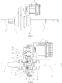
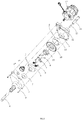
- a garden tool power system with automatic walking function comprises a motor 14, a reducer and a transmission shaft.
- the motor 14 transmits the power to the transmission shaft through the reducer to drive wheels provided on the transmission shaft to rotate.
- the reducer includes a pinion 15 connected to an output end of the motor 14 and a gear 16 engaging with the pinion 15 and mounted on the transmission shaft.
- the garden tool power system is walked automatically when the wheels provided on the transmission shaft are driven to rotate by the power transmitted from the motor 14 to the transmission shaft through the reducer.
- the motor 14, the reducer and the transmission shaft are together formed a power system of the garden tool power system.
- the garden tool power system can be also manually pulled or pushed to walk forward and back by the operator without the power system.
- the reducer has a housing for receiving the pinion 15 and the gear 16.
- the housing includes left and right housings 2, 12. assembled together through a blot 9.
- the pinion 15 is mounted to the left housing 2 through a bearing 17.
- the pinion 15 is driven to rotate by the rotation of the motor 14.
- the actual speed of the lawn mower can be reduced by setting the teeth number Z1 of the gear 16 and the teeth number Z2 of the pinion 15 basing on the rotating speed ration N2/N1 being equal to the transmission gear ratio Z1/Z2, wherein N2 represents the rotating speed of the pinion 15, N1 represents the rotating speed of the gear 16.
- the transmission shaft comprises left and right shafts 1, 11 respectively assembled to the left and right housings 2, 12 of the reducer through corresponding bearing 3, and a connecting shaft 13 connecting the left shaft 1 to the right shaft 11.
- the connecting shaft 13 is respectively connected with the left and right shafts 1, 11 through transition fit to reduce the vibration of the garden tool power system while working.
- the gear 16 is assembled on the connecting shaft 13 through clearance fit to prevent the connecting shaft 13 transmitting torque to the gear 16 while rotating.
- the gear 16 has at least two guiding rods 8 transversely arranged thereon and the guiding rods 8 are fixed to the gear 16 through a pressure plate 7.
- Two centrifugal blocks 18 are located between the guiding rods 8.
- Each guiding rod 8 has a spring 6 surrounded therearound and the spring 6 defines two opposite ends abutting against the corresponding portion of the centrifugal blocks 18.
- a fixing sleeve provided on the periphery of the centrifugal blocks 18 includes a left fixing sleeve 5 mounted on the left housing 2 and a right fixing sleeve 10 mounted on the right housing 12.
- the left and right fixing sleeves 5, 10 are respectively fixed to the left and right shafts 1, 11 through corresponding positioning pins 4.
- Each of the left and right fixing sleeves 5, 10 is provided with buckle structures on the inner wall thereof.
- the buckle structures are convex portions symmetrically defined on the inner walls of the left and right fixing sleeves 5, 10.
- the convex portions matches with the centrifugal block 18 in a jaw-clutch manner to transmit torque.
- the operation process of the garden tool power system with automatic walking function are described as follows:
- the motor 14 transmits kinetic energy to the pinion 15 due to the gear transmission between the motor 14 and the pinion 15 when the motor 14 is started, and the pinion 15 transmits kinetic energy to the gear 16 through the gear transmission between the pinion 15 and the gear 16, and the gear 16 is driven to rotate by the pinion 15 when the kinetic energy is transmitted from the pinion 15 to the gear 16, but the connecting shaft 13 and the left and right shafts 1, 11 respectively connected to the connecting shaft 13 are not rotated basing on the clearance fit between the connecting shaft 13 and the gear 16.
- the garden tool power system does not walk automatically at this point.
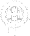
- centrifugal blocks 18 mounted on the gear 16 centrifugally and outwardly move along the guiding rod 8 when overcoming the resistance from the spring 6 and are stopped moving when engaging with the convex portions of the left and right fixing sleeves 5, 10 in a jaw-clutch manner to transmit torque.
- the left and right shafts 1, 11 respectively drive the wheels provided thereon to rotate, so that the garden tool achieves the automatically walking function or self-propelling waking function, referring to FIG. 3 .
- the centrifugal force of the centrifugal blocks 18 is bigger than the tensile force of the corresponding spring 6.
- the centrifugal blocks 18 can move backward to the initial position along the guiding rods 8 after overcoming the gravity thereof. And the centrifugal blocks 18 are separated from the fixing sleeve 5, 10 to stop transmitting torque, as shown in Fig. 4 , so that the garden tool can be manually pulled or pushed by the operator to walk forward and back at this moment.
- the left and right shafts 1, 11 and the connecting shaft 13 can rotate to transmit torque due to no friction caused by the clearance fit between the gear 16 and the connecting shaft 13 and the transition fit between the connecting shaft 13 and the left and right shaft 1, 11, so as to separate the reducer from the motor 14.
- the garden tool can achieve automatically walking function or self-propelling walking function when the motor 14 is working and manually pulled or pushed by the operator to walk forward and back when the motor 14 is stopped working. In this manner, the garden tool can easily change the working status from the self-propelling walking status to manually walking status. And the working efficiency of the garden tool is improved and the manufacturing cost is reduced basing on the simple structure of the reducer.
Landscapes
- Engineering & Computer Science (AREA)
- General Engineering & Computer Science (AREA)
- Life Sciences & Earth Sciences (AREA)
- Environmental Sciences (AREA)
- Mechanical Engineering (AREA)
- Harvester Elements (AREA)
- Rehabilitation Tools (AREA)
- Soil Working Implements (AREA)
Applications Claiming Priority (2)
| Application Number | Priority Date | Filing Date | Title |
|---|---|---|---|
| CN201510504564.3A CN105165262B (zh) | 2015-08-18 | 2015-08-18 | 带自行走功能的园林工具动力系统 |
| PCT/CN2016/077174 WO2017028530A1 (zh) | 2015-08-18 | 2016-03-23 | 带自行走功能的园林工具动力系统 |
Publications (3)
| Publication Number | Publication Date |
|---|---|
| EP3338530A1 true EP3338530A1 (de) | 2018-06-27 |
| EP3338530A4 EP3338530A4 (de) | 2019-04-24 |
| EP3338530B1 EP3338530B1 (de) | 2021-02-24 |
Family
ID=54888154
Family Applications (1)
| Application Number | Title | Priority Date | Filing Date |
|---|---|---|---|
| EP16836395.0A Active EP3338530B1 (de) | 2015-08-18 | 2016-03-23 | Antriebssystem für gartenwerkzeug mit automatischer gehfunktion |
Country Status (5)
| Country | Link |
|---|---|
| US (2) | US10645878B2 (de) |
| EP (1) | EP3338530B1 (de) |
| CN (1) | CN105165262B (de) |
| ES (1) | ES2863229T3 (de) |
| WO (1) | WO2017028530A1 (de) |
Cited By (3)
| Publication number | Priority date | Publication date | Assignee | Title |
|---|---|---|---|---|
| WO2021144526A1 (fr) | 2020-01-17 | 2021-07-22 | France Reducteurs | Boîtier de transmission et son procédé de montage, et engin automoteur équipé d'un tel boîtier de transmission |
| FR3106383A1 (fr) * | 2020-01-17 | 2021-07-23 | France Reducteurs | boîtier de transmission et son procédé de montage, et engin automoteur équipé d’un tel boîtier de transmission |
| IT202200007139A1 (it) * | 2022-04-11 | 2023-10-11 | Stiga S P A In Breve Anche St S P A | “Robot tosaerba con blocco motore di trazione atto a rilevare un ostacolo” |
Families Citing this family (20)
| Publication number | Priority date | Publication date | Assignee | Title |
|---|---|---|---|---|
| CN105165262B (zh) * | 2015-08-18 | 2017-07-11 | 常州格力博有限公司 | 带自行走功能的园林工具动力系统 |
| CN105960950B (zh) * | 2015-12-29 | 2019-06-18 | 常州格力博有限公司 | 一种割草机 |
| CN105940869A (zh) * | 2016-05-05 | 2016-09-21 | 常州格力博有限公司 | 自走系统及其园林工具 |
| CN105830645A (zh) * | 2016-05-05 | 2016-08-10 | 常州格力博有限公司 | 自走系统及其园林工具 |
| CN105960948A (zh) * | 2016-05-05 | 2016-09-28 | 常州格力博有限公司 | 自走系统及其园林工具 |
| CN206753790U (zh) * | 2017-01-25 | 2017-12-15 | 浙江白马实业有限公司 | 一种汽油机启动中转器 |
| CN110608387B (zh) * | 2019-09-18 | 2024-04-19 | 上海碧枫实业发展有限公司 | 一种亚克力制造的灯结构 |
| CN112178142A (zh) * | 2020-09-08 | 2021-01-05 | 中油国家油气钻井装备工程技术研究中心有限公司 | 一种钻台机械手用回转和偏移双作用传动装置 |
| CN112013044B (zh) * | 2020-09-22 | 2025-07-01 | 深圳市园睛智能科技有限公司 | 一种驱动系统用离合机构及驱动系统 |
| CN112228517B (zh) * | 2020-11-10 | 2022-04-05 | 泰兴市海虹机械制造有限公司 | 一种双输入行星齿轮减速机构 |
| US12439846B2 (en) | 2021-04-19 | 2025-10-14 | Milwaukee Electric Tool Corporation | String trimmer head |
| US12376515B2 (en) | 2021-06-30 | 2025-08-05 | Milwaukee Electric Tool Corporation | String trimmer assembly and trimmer head for use with same |
| CN222193146U (zh) | 2021-06-30 | 2024-12-20 | 米沃奇电动工具公司 | 修剪机头及线式修剪机 |
| DE112022002536T5 (de) | 2021-06-30 | 2024-02-29 | Milwaukee Electric Tool Corporation | Fadentrimmerkopf |
| CN114303646B (zh) * | 2022-01-20 | 2026-01-02 | 浙江三锋实业股份有限公司 | 一种自走器 |
| CN117128257A (zh) | 2022-05-18 | 2023-11-28 | 米沃奇电动工具公司 | 离合器机构 |
| EP4775015A2 (de) | 2022-07-29 | 2026-07-15 | Techtronic Cordless GP | Zentrifugalkupplungsmechanismen |
| CN118104479A (zh) * | 2023-09-16 | 2024-05-31 | 宁波恒驰工具有限公司 | 一种自走驱动装置、设备及园林工具 |
| CN117227463A (zh) * | 2023-09-26 | 2023-12-15 | 格力博(江苏)股份有限公司 | 轮式工具及行走机构 |
| CN222532262U (zh) * | 2024-05-20 | 2025-02-28 | 浙江亚特电器股份有限公司 | 一种园林工具的差速自走器及园林工具 |
Family Cites Families (38)
| Publication number | Priority date | Publication date | Assignee | Title |
|---|---|---|---|---|
| US2194228A (en) * | 1938-05-16 | 1940-03-19 | William A Jex | One-way clutch |
| DE1550764B1 (de) * | 1966-10-07 | 1971-09-09 | Fichtel & Sachs Ag | Fliehkraftkupplung insbesondere fuer schaltgetriebe |
| SE374176C (sv) * | 1973-07-09 | 1982-11-08 | Partner Ab | Frikopplingsanordning vid centrifugalkoppling |
| DE2936009C2 (de) * | 1979-09-06 | 1983-04-21 | Getrag Getriebe- Und Zahnradfabrik Gmbh, 7140 Ludwigsburg | Stufengetriebe für Straßenkraftfahrzeuge in Vorgelegebauart |
| US4458795A (en) * | 1982-06-28 | 1984-07-10 | Peter Norton | Coupling for drive shaft and servo-motor driven shaft |
| US6354978B1 (en) * | 1999-10-26 | 2002-03-12 | Simplicity Manufacturing, Inc. | Differential and method for variable traction control |
| FR2801951B1 (fr) * | 1999-12-07 | 2002-01-04 | France Reducteurs Sa | Transmission pour engin autotracte et engin roulant autotracte, en particulier tondeuse a gazon |
| ATE334319T1 (de) * | 2004-03-04 | 2006-08-15 | Bi Ci Di S R L | Kraftübertragungseinrichtung für zwei oder mehr wellen |
| CN2715505Y (zh) * | 2004-07-23 | 2005-08-10 | 常州合力电器有限公司 | 后置式电动修草机的传动机构 |
| FR2885656B1 (fr) * | 2005-05-13 | 2009-05-15 | France Reducteurs Sa Sa | Boitier de transmission pour engin roulant notamment a conducteur marchant |
| FR2885655B1 (fr) * | 2005-05-13 | 2007-06-29 | France Reducteurs Sa Sa | Boitier de transmission perfectionne pour engin roulant |
| JP4776435B2 (ja) * | 2006-05-24 | 2011-09-21 | 本田技研工業株式会社 | 自走式作業機の走行駆動機構 |
| JP4578434B2 (ja) * | 2006-05-24 | 2010-11-10 | 本田技研工業株式会社 | 自走式作業機の負荷制御機構 |
| WO2007139469A1 (en) * | 2006-05-26 | 2007-12-06 | Leif Persson | Power transmission for a lawn mower and a lawn mower provided with such a transmission |
| JP5216648B2 (ja) | 2009-03-25 | 2013-06-19 | カーツ株式会社 | エンジン及び本機の接続分離構造 |
| US20110017168A1 (en) * | 2009-07-24 | 2011-01-27 | Briggs & Stratton Corporation | Weighted centrifugal clutch |
| KR20110005640U (ko) | 2009-12-01 | 2011-06-09 | 주식회사 공성 | 농업용 전동 작업차 |
| JP5738117B2 (ja) * | 2010-08-05 | 2015-06-17 | アスモ株式会社 | クラッチ、モータ及び車両用ドア開閉装置 |
| FR2966536B1 (fr) * | 2010-10-25 | 2012-10-26 | France Reducteurs | Boitier de mecanisme de transmission, notamment pour une transmission entre un arbre primaire moteur et un arbre de sortie |
| FR2967738B1 (fr) * | 2010-11-22 | 2012-12-07 | France Reducteurs | Dispositif de transmission pour engin automoteur et engin automoteur equipe d'une telle transmission |
| CN102349396A (zh) | 2011-08-30 | 2012-02-15 | 福建省晋江市三力机车有限公司 | 一种自走式割草机的离合传动装置 |
| CN202455866U (zh) * | 2011-12-22 | 2012-10-03 | 浙江三锋实业股份有限公司 | 一种园林工具的自动刹车装置 |
| CN202496213U (zh) * | 2012-01-11 | 2012-10-24 | 杨健 | 一种带有自动离合器的割草机 |
| FR3004771B1 (fr) * | 2013-04-23 | 2015-04-17 | France Reducteurs | Transmission pour engin roulant a conducteur marchant, et engin roulant equipe d'une telle transmission |
| CN203492404U (zh) * | 2013-08-30 | 2014-03-26 | 福建珠峰动力机械有限公司 | 电动割草机刹车装置 |
| CN203492380U (zh) | 2013-09-18 | 2014-03-26 | 常州合力电器有限公司 | 电动园林机 |
| CN203851503U (zh) | 2014-03-05 | 2014-10-01 | 浙江亚特电器有限公司 | 一种电动园林工具 |
| CN104913010B (zh) * | 2014-03-10 | 2017-09-05 | 天佑电器(苏州)有限公司 | 双离合结构减速器 |
| CN104798541A (zh) | 2015-03-24 | 2015-07-29 | 浙江亚特电器有限公司 | 一种割草机自走装置 |
| CN105165262B (zh) | 2015-08-18 | 2017-07-11 | 常州格力博有限公司 | 带自行走功能的园林工具动力系统 |
| CN204994274U (zh) * | 2015-08-18 | 2016-01-27 | 常州格力博有限公司 | 带自行走功能的园林工具动力系统 |
| KR101755943B1 (ko) * | 2015-12-15 | 2017-07-07 | 현대자동차주식회사 | 역구동성이 향상된 하모닉 감속기, 그를 포함하는 구동 모듈 및 구동 모듈을 제어하는 방법 |
| JP6230642B2 (ja) * | 2016-03-17 | 2017-11-15 | 本田技研工業株式会社 | 歩行型芝刈機 |
| JP6663758B2 (ja) | 2016-03-17 | 2020-03-13 | 本田技研工業株式会社 | 歩行型芝刈機 |
| US11272657B2 (en) * | 2016-04-25 | 2022-03-15 | Trimverse LLC | Strand feed mechanism for a strand trimmer |
| EP3354924B1 (de) * | 2017-01-11 | 2020-07-01 | Canon Kabushiki Kaisha | Kupplung, antriebsgetriebevorrichtung und bilderzeugungsvorrichtung |
| CN109747698B (zh) * | 2017-11-08 | 2020-05-26 | 南京德朔实业有限公司 | 手推式自驱行进机器 |
| US11096328B2 (en) * | 2018-12-27 | 2021-08-24 | Cnh Industrial America Llc | Agricultural header with damage-reducing clutch |
-
2015
- 2015-08-18 CN CN201510504564.3A patent/CN105165262B/zh active Active
-
2016
- 2016-03-23 WO PCT/CN2016/077174 patent/WO2017028530A1/zh not_active Ceased
- 2016-03-23 EP EP16836395.0A patent/EP3338530B1/de active Active
- 2016-03-23 US US15/753,025 patent/US10645878B2/en active Active
- 2016-03-23 ES ES16836395T patent/ES2863229T3/es active Active
-
2020
- 2020-05-11 US US16/871,404 patent/US10980180B2/en active Active
Cited By (7)
| Publication number | Priority date | Publication date | Assignee | Title |
|---|---|---|---|---|
| WO2021144526A1 (fr) | 2020-01-17 | 2021-07-22 | France Reducteurs | Boîtier de transmission et son procédé de montage, et engin automoteur équipé d'un tel boîtier de transmission |
| FR3106383A1 (fr) * | 2020-01-17 | 2021-07-23 | France Reducteurs | boîtier de transmission et son procédé de montage, et engin automoteur équipé d’un tel boîtier de transmission |
| DE112021000250T5 (de) | 2020-01-17 | 2022-09-01 | France Reducteurs | Getriebegehäuse und Verfahren zu dessen Montage und mit einem solchen Getriebegehäuse ausgerüstetes selbstfahrendes Gerät |
| DE112021000250B4 (de) * | 2020-01-17 | 2025-07-03 | France Reducteurs | Getriebegehäuse und mit einem solchen Getriebegehäuse ausgerüstetes selbstfahrendes Gerät |
| US12520751B2 (en) | 2020-01-17 | 2026-01-13 | France Reducteurs | Transmission casing, method for mounting same, and self-propelled vehicle provided with such a transmission casing |
| IT202200007139A1 (it) * | 2022-04-11 | 2023-10-11 | Stiga S P A In Breve Anche St S P A | “Robot tosaerba con blocco motore di trazione atto a rilevare un ostacolo” |
| EP4260675A1 (de) * | 2022-04-11 | 2023-10-18 | Stiga S.p.A. in breve anche St. S.p.A. | Roboterrasenmäher mit antriebsmotorblock zur erkennung eines hindernisses |
Also Published As
| Publication number | Publication date |
|---|---|
| US10645878B2 (en) | 2020-05-12 |
| WO2017028530A1 (zh) | 2017-02-23 |
| EP3338530B1 (de) | 2021-02-24 |
| EP3338530A4 (de) | 2019-04-24 |
| CN105165262A (zh) | 2015-12-23 |
| US10980180B2 (en) | 2021-04-20 |
| ES2863229T3 (es) | 2021-10-11 |
| CN105165262B (zh) | 2017-07-11 |
| US20180242526A1 (en) | 2018-08-30 |
| US20200267902A1 (en) | 2020-08-27 |
Similar Documents
| Publication | Publication Date | Title |
|---|---|---|
| US10645878B2 (en) | Garden tool power system with automatic walking function | |
| EP2602504B1 (de) | Schutzkupplung | |
| US9393711B2 (en) | Hand-held knockout punch driver | |
| CN102741024B (zh) | 具有无刷电机的电池驱动的电动工具 | |
| US20150245559A1 (en) | Lawn mower with an automatic clutch | |
| CN101933443B (zh) | 切割装置 | |
| EP3061339B1 (de) | Gartenwerkzeug | |
| US8695223B2 (en) | Bush cutter with a versatile operating rod | |
| EP2910340A1 (de) | Kupplung für Elektrowerkzeug, Verfahren zur Herstellung des Werkzeugs und Verfahren zum Betrieben des Werkzeugs | |
| US20250075750A1 (en) | Centrifugal clutch mechanisms | |
| CN104602510A (zh) | 具有至少一个往复刀片的动力工具 | |
| EP2491780A1 (de) | Schwingungsdämpfungsmechanismus und arbeitsmaschine damit | |
| CN205694486U (zh) | 绝缘结构及修枝机 | |
| EP2666595A1 (de) | Planetengetriebe mit Schutzkupplung | |
| US12352324B2 (en) | Clutch mechanism | |
| US4281504A (en) | Automatic safety clutch device for flexible drives | |
| EP1538360A1 (de) | Fliehkraftkupplung mit Schuh Bindung | |
| CN205179748U (zh) | 一种草地割草机 | |
| US20170191531A1 (en) | Coupling shafts in axial alignment | |
| CN106164467B (zh) | 用于热机的起动器组件 | |
| CN106837650B (zh) | 起动机及其中驱动齿轮结构的组装方法 | |
| KR20200055451A (ko) | 충전식 예초기 | |
| KR100864302B1 (ko) | 클러치 및 이 클러치가 적용된 동력전달장치 | |
| US9890821B2 (en) | Clutch for electric tool | |
| JPH0320590Y2 (de) |
Legal Events
| Date | Code | Title | Description |
|---|---|---|---|
| STAA | Information on the status of an ep patent application or granted ep patent |
Free format text: STATUS: THE INTERNATIONAL PUBLICATION HAS BEEN MADE |
|
| PUAI | Public reference made under article 153(3) epc to a published international application that has entered the european phase |
Free format text: ORIGINAL CODE: 0009012 |
|
| STAA | Information on the status of an ep patent application or granted ep patent |
Free format text: STATUS: REQUEST FOR EXAMINATION WAS MADE |
|
| 17P | Request for examination filed |
Effective date: 20180216 |
|
| AK | Designated contracting states |
Kind code of ref document: A1 Designated state(s): AL AT BE BG CH CY CZ DE DK EE ES FI FR GB GR HR HU IE IS IT LI LT LU LV MC MK MT NL NO PL PT RO RS SE SI SK SM TR |
|
| AX | Request for extension of the european patent |
Extension state: BA ME |
|
| RIN1 | Information on inventor provided before grant (corrected) |
Inventor name: ZHANG, WEI Inventor name: GUAN, XIAODONG |
|
| DAV | Request for validation of the european patent (deleted) | ||
| DAX | Request for extension of the european patent (deleted) | ||
| A4 | Supplementary search report drawn up and despatched |
Effective date: 20190321 |
|
| RIC1 | Information provided on ipc code assigned before grant |
Ipc: A01D 34/68 20060101ALI20190315BHEP Ipc: A01D 69/02 20060101AFI20190315BHEP Ipc: F16D 43/18 20060101ALI20190315BHEP |
|
| RAP1 | Party data changed (applicant data changed or rights of an application transferred) |
Owner name: GLOBE (JIANGSU) CO., LTD. |
|
| REG | Reference to a national code |
Ref country code: DE Ref legal event code: R079 Ref document number: 602016053287 Country of ref document: DE Free format text: PREVIOUS MAIN CLASS: A01D0069020000 Ipc: A01D0034680000 |
|
| RIC1 | Information provided on ipc code assigned before grant |
Ipc: A01D 69/08 20060101ALI20200930BHEP Ipc: A01D 69/02 20060101ALI20200930BHEP Ipc: A01D 34/68 20060101AFI20200930BHEP Ipc: F16D 43/18 20060101ALI20200930BHEP |
|
| GRAP | Despatch of communication of intention to grant a patent |
Free format text: ORIGINAL CODE: EPIDOSNIGR1 |
|
| STAA | Information on the status of an ep patent application or granted ep patent |
Free format text: STATUS: GRANT OF PATENT IS INTENDED |
|
| INTG | Intention to grant announced |
Effective date: 20201111 |
|
| GRAS | Grant fee paid |
Free format text: ORIGINAL CODE: EPIDOSNIGR3 |
|
| GRAA | (expected) grant |
Free format text: ORIGINAL CODE: 0009210 |
|
| STAA | Information on the status of an ep patent application or granted ep patent |
Free format text: STATUS: THE PATENT HAS BEEN GRANTED |
|
| AK | Designated contracting states |
Kind code of ref document: B1 Designated state(s): AL AT BE BG CH CY CZ DE DK EE ES FI FR GB GR HR HU IE IS IT LI LT LU LV MC MK MT NL NO PL PT RO RS SE SI SK SM TR |
|
| REG | Reference to a national code |
Ref country code: CH Ref legal event code: EP |
|
| REG | Reference to a national code |
Ref country code: DE Ref legal event code: R096 Ref document number: 602016053287 Country of ref document: DE |
|
| REG | Reference to a national code |
Ref country code: AT Ref legal event code: REF Ref document number: 1363295 Country of ref document: AT Kind code of ref document: T Effective date: 20210315 |
|
| REG | Reference to a national code |
Ref country code: IE Ref legal event code: FG4D |
|
| REG | Reference to a national code |
Ref country code: SE Ref legal event code: TRGR |
|
| REG | Reference to a national code |
Ref country code: LT Ref legal event code: MG9D |
|
| REG | Reference to a national code |
Ref country code: NL Ref legal event code: MP Effective date: 20210224 |
|
| PG25 | Lapsed in a contracting state [announced via postgrant information from national office to epo] |
Ref country code: GR Free format text: LAPSE BECAUSE OF FAILURE TO SUBMIT A TRANSLATION OF THE DESCRIPTION OR TO PAY THE FEE WITHIN THE PRESCRIBED TIME-LIMIT Effective date: 20210525 Ref country code: FI Free format text: LAPSE BECAUSE OF FAILURE TO SUBMIT A TRANSLATION OF THE DESCRIPTION OR TO PAY THE FEE WITHIN THE PRESCRIBED TIME-LIMIT Effective date: 20210224 Ref country code: HR Free format text: LAPSE BECAUSE OF FAILURE TO SUBMIT A TRANSLATION OF THE DESCRIPTION OR TO PAY THE FEE WITHIN THE PRESCRIBED TIME-LIMIT Effective date: 20210224 Ref country code: PT Free format text: LAPSE BECAUSE OF FAILURE TO SUBMIT A TRANSLATION OF THE DESCRIPTION OR TO PAY THE FEE WITHIN THE PRESCRIBED TIME-LIMIT Effective date: 20210624 Ref country code: NO Free format text: LAPSE BECAUSE OF FAILURE TO SUBMIT A TRANSLATION OF THE DESCRIPTION OR TO PAY THE FEE WITHIN THE PRESCRIBED TIME-LIMIT Effective date: 20210524 Ref country code: BG Free format text: LAPSE BECAUSE OF FAILURE TO SUBMIT A TRANSLATION OF THE DESCRIPTION OR TO PAY THE FEE WITHIN THE PRESCRIBED TIME-LIMIT Effective date: 20210524 Ref country code: LT Free format text: LAPSE BECAUSE OF FAILURE TO SUBMIT A TRANSLATION OF THE DESCRIPTION OR TO PAY THE FEE WITHIN THE PRESCRIBED TIME-LIMIT Effective date: 20210224 |
|
| REG | Reference to a national code |
Ref country code: AT Ref legal event code: MK05 Ref document number: 1363295 Country of ref document: AT Kind code of ref document: T Effective date: 20210224 |
|
| PG25 | Lapsed in a contracting state [announced via postgrant information from national office to epo] |
Ref country code: PL Free format text: LAPSE BECAUSE OF FAILURE TO SUBMIT A TRANSLATION OF THE DESCRIPTION OR TO PAY THE FEE WITHIN THE PRESCRIBED TIME-LIMIT Effective date: 20210224 Ref country code: LV Free format text: LAPSE BECAUSE OF FAILURE TO SUBMIT A TRANSLATION OF THE DESCRIPTION OR TO PAY THE FEE WITHIN THE PRESCRIBED TIME-LIMIT Effective date: 20210224 Ref country code: NL Free format text: LAPSE BECAUSE OF FAILURE TO SUBMIT A TRANSLATION OF THE DESCRIPTION OR TO PAY THE FEE WITHIN THE PRESCRIBED TIME-LIMIT Effective date: 20210224 Ref country code: RS Free format text: LAPSE BECAUSE OF FAILURE TO SUBMIT A TRANSLATION OF THE DESCRIPTION OR TO PAY THE FEE WITHIN THE PRESCRIBED TIME-LIMIT Effective date: 20210224 |
|
| PG25 | Lapsed in a contracting state [announced via postgrant information from national office to epo] |
Ref country code: IS Free format text: LAPSE BECAUSE OF FAILURE TO SUBMIT A TRANSLATION OF THE DESCRIPTION OR TO PAY THE FEE WITHIN THE PRESCRIBED TIME-LIMIT Effective date: 20210624 |
|
| REG | Reference to a national code |
Ref country code: ES Ref legal event code: FG2A Ref document number: 2863229 Country of ref document: ES Kind code of ref document: T3 Effective date: 20211011 |
|
| PG25 | Lapsed in a contracting state [announced via postgrant information from national office to epo] |
Ref country code: SM Free format text: LAPSE BECAUSE OF FAILURE TO SUBMIT A TRANSLATION OF THE DESCRIPTION OR TO PAY THE FEE WITHIN THE PRESCRIBED TIME-LIMIT Effective date: 20210224 Ref country code: AT Free format text: LAPSE BECAUSE OF FAILURE TO SUBMIT A TRANSLATION OF THE DESCRIPTION OR TO PAY THE FEE WITHIN THE PRESCRIBED TIME-LIMIT Effective date: 20210224 Ref country code: EE Free format text: LAPSE BECAUSE OF FAILURE TO SUBMIT A TRANSLATION OF THE DESCRIPTION OR TO PAY THE FEE WITHIN THE PRESCRIBED TIME-LIMIT Effective date: 20210224 |
|
| REG | Reference to a national code |
Ref country code: DE Ref legal event code: R097 Ref document number: 602016053287 Country of ref document: DE |
|
| PG25 | Lapsed in a contracting state [announced via postgrant information from national office to epo] |
Ref country code: SK Free format text: LAPSE BECAUSE OF FAILURE TO SUBMIT A TRANSLATION OF THE DESCRIPTION OR TO PAY THE FEE WITHIN THE PRESCRIBED TIME-LIMIT Effective date: 20210224 Ref country code: RO Free format text: LAPSE BECAUSE OF FAILURE TO SUBMIT A TRANSLATION OF THE DESCRIPTION OR TO PAY THE FEE WITHIN THE PRESCRIBED TIME-LIMIT Effective date: 20210224 Ref country code: DK Free format text: LAPSE BECAUSE OF FAILURE TO SUBMIT A TRANSLATION OF THE DESCRIPTION OR TO PAY THE FEE WITHIN THE PRESCRIBED TIME-LIMIT Effective date: 20210224 Ref country code: MC Free format text: LAPSE BECAUSE OF FAILURE TO SUBMIT A TRANSLATION OF THE DESCRIPTION OR TO PAY THE FEE WITHIN THE PRESCRIBED TIME-LIMIT Effective date: 20210224 |
|
| REG | Reference to a national code |
Ref country code: BE Ref legal event code: MM Effective date: 20210331 |
|
| PLBE | No opposition filed within time limit |
Free format text: ORIGINAL CODE: 0009261 |
|
| STAA | Information on the status of an ep patent application or granted ep patent |
Free format text: STATUS: NO OPPOSITION FILED WITHIN TIME LIMIT |
|
| PG25 | Lapsed in a contracting state [announced via postgrant information from national office to epo] |
Ref country code: IE Free format text: LAPSE BECAUSE OF NON-PAYMENT OF DUE FEES Effective date: 20210323 Ref country code: AL Free format text: LAPSE BECAUSE OF FAILURE TO SUBMIT A TRANSLATION OF THE DESCRIPTION OR TO PAY THE FEE WITHIN THE PRESCRIBED TIME-LIMIT Effective date: 20210224 Ref country code: LU Free format text: LAPSE BECAUSE OF NON-PAYMENT OF DUE FEES Effective date: 20210323 |
|
| 26N | No opposition filed |
Effective date: 20211125 |
|
| PG25 | Lapsed in a contracting state [announced via postgrant information from national office to epo] |
Ref country code: SI Free format text: LAPSE BECAUSE OF FAILURE TO SUBMIT A TRANSLATION OF THE DESCRIPTION OR TO PAY THE FEE WITHIN THE PRESCRIBED TIME-LIMIT Effective date: 20210224 |
|
| PG25 | Lapsed in a contracting state [announced via postgrant information from national office to epo] |
Ref country code: IS Free format text: LAPSE BECAUSE OF FAILURE TO SUBMIT A TRANSLATION OF THE DESCRIPTION OR TO PAY THE FEE WITHIN THE PRESCRIBED TIME-LIMIT Effective date: 20210624 |
|
| PG25 | Lapsed in a contracting state [announced via postgrant information from national office to epo] |
Ref country code: BE Free format text: LAPSE BECAUSE OF NON-PAYMENT OF DUE FEES Effective date: 20210331 |
|
| PG25 | Lapsed in a contracting state [announced via postgrant information from national office to epo] |
Ref country code: CY Free format text: LAPSE BECAUSE OF FAILURE TO SUBMIT A TRANSLATION OF THE DESCRIPTION OR TO PAY THE FEE WITHIN THE PRESCRIBED TIME-LIMIT Effective date: 20210224 |
|
| PG25 | Lapsed in a contracting state [announced via postgrant information from national office to epo] |
Ref country code: HU Free format text: LAPSE BECAUSE OF FAILURE TO SUBMIT A TRANSLATION OF THE DESCRIPTION OR TO PAY THE FEE WITHIN THE PRESCRIBED TIME-LIMIT; INVALID AB INITIO Effective date: 20160323 |
|
| PG25 | Lapsed in a contracting state [announced via postgrant information from national office to epo] |
Ref country code: MK Free format text: LAPSE BECAUSE OF FAILURE TO SUBMIT A TRANSLATION OF THE DESCRIPTION OR TO PAY THE FEE WITHIN THE PRESCRIBED TIME-LIMIT Effective date: 20210224 |
|
| PG25 | Lapsed in a contracting state [announced via postgrant information from national office to epo] |
Ref country code: MT Free format text: LAPSE BECAUSE OF FAILURE TO SUBMIT A TRANSLATION OF THE DESCRIPTION OR TO PAY THE FEE WITHIN THE PRESCRIBED TIME-LIMIT Effective date: 20210224 |
|
| PG25 | Lapsed in a contracting state [announced via postgrant information from national office to epo] |
Ref country code: TR Free format text: LAPSE BECAUSE OF FAILURE TO SUBMIT A TRANSLATION OF THE DESCRIPTION OR TO PAY THE FEE WITHIN THE PRESCRIBED TIME-LIMIT Effective date: 20210224 |
|
| REG | Reference to a national code |
Ref country code: CH Ref legal event code: U11 Free format text: ST27 STATUS EVENT CODE: U-0-0-U10-U11 (AS PROVIDED BY THE NATIONAL OFFICE) Effective date: 20260401 |
|
| PGFP | Annual fee paid to national office [announced via postgrant information from national office to epo] |
Ref country code: SE Payment date: 20260323 Year of fee payment: 11 |
|
| PGFP | Annual fee paid to national office [announced via postgrant information from national office to epo] |
Ref country code: GB Payment date: 20260324 Year of fee payment: 11 |
|
| PGFP | Annual fee paid to national office [announced via postgrant information from national office to epo] |
Ref country code: DE Payment date: 20260320 Year of fee payment: 11 |
|
| PGFP | Annual fee paid to national office [announced via postgrant information from national office to epo] |
Ref country code: FR Payment date: 20260324 Year of fee payment: 11 |
|
| PGFP | Annual fee paid to national office [announced via postgrant information from national office to epo] |
Ref country code: CZ Payment date: 20260311 Year of fee payment: 11 |
|
| PGFP | Annual fee paid to national office [announced via postgrant information from national office to epo] |
Ref country code: ES Payment date: 20260420 Year of fee payment: 11 |
|
| PGFP | Annual fee paid to national office [announced via postgrant information from national office to epo] |
Ref country code: IT Payment date: 20260331 Year of fee payment: 11 |
|
| PGFP | Annual fee paid to national office [announced via postgrant information from national office to epo] |
Ref country code: CH Payment date: 20260401 Year of fee payment: 11 |