EP3338532A1 - Engin de récolte agricole ainsi que procédé de déchargement d'un tel engin de récolte - Google Patents
Engin de récolte agricole ainsi que procédé de déchargement d'un tel engin de récolte Download PDFInfo
- Publication number
- EP3338532A1 EP3338532A1 EP17208527.6A EP17208527A EP3338532A1 EP 3338532 A1 EP3338532 A1 EP 3338532A1 EP 17208527 A EP17208527 A EP 17208527A EP 3338532 A1 EP3338532 A1 EP 3338532A1
- Authority
- EP
- European Patent Office
- Prior art keywords
- unloading
- conveyor
- crop
- width
- speed
- Prior art date
- Legal status (The legal status is an assumption and is not a legal conclusion. Google has not performed a legal analysis and makes no representation as to the accuracy of the status listed.)
- Granted
Links
Images


Classifications
-
- A—HUMAN NECESSITIES
- A01—AGRICULTURE; FORESTRY; ANIMAL HUSBANDRY; HUNTING; TRAPPING; FISHING
- A01D—HARVESTING; MOWING
- A01D90/00—Vehicles for carrying harvested crops with means for selfloading or unloading
- A01D90/10—Unloading means
-
- A—HUMAN NECESSITIES
- A01—AGRICULTURE; FORESTRY; ANIMAL HUSBANDRY; HUNTING; TRAPPING; FISHING
- A01F—PROCESSING OF HARVESTED PRODUCE; HAY OR STRAW PRESSES; DEVICES FOR STORING AGRICULTURAL OR HORTICULTURAL PRODUCE
- A01F25/00—Storing agricultural or horticultural produce; Hanging-up harvested fruit
- A01F25/16—Arrangements in forage silos
- A01F25/18—Loading or distributing arrangements
- A01F25/186—Distributing arrangements
-
- A—HUMAN NECESSITIES
- A01—AGRICULTURE; FORESTRY; ANIMAL HUSBANDRY; HUNTING; TRAPPING; FISHING
- A01C—PLANTING; SOWING; FERTILISING
- A01C3/00—Treating manure; Manuring
- A01C3/06—Manure distributors, e.g. dung distributors
Definitions
- the present invention generally relates to the production of a crop carpet in a silo.
- the invention relates on the one hand to an agricultural crop cart with a loading space for picking up crop, a discharge conveyor for unloading the crop from the loading space, and a Boothnverteilvorraum for transverse distribution of the crop during unloading from the hold.
- the invention relates to a method for unloading such a harvesting trolley for producing a Erntegutteppichs in a silo in which unloaded by the unloading conveyor from the hold of the Erntegutwagens crop while the Erntegutwagen is driven along a guideway through the silo.
- the Erntegutteich should thereby along the track through the silo on the one hand as constant as possible carpet thickness and on the other hand as constant as possible carpet width possess, wherein the constant carpet thickness is to be maintained over several tramlines away to produce a total uniform Silomatte.
- the carpet width should be constant, at least along a tram to be able to connect flush in the next tram.
- the uniform unloading is made more difficult if different carpet thicknesses are desired for different crop compositions or different carpet widths are to be stored in a tram, which increases the complexity for the tractor operator.
- the font EP 3 078 256 A1 shows a Erntegutwagen with such Boothnverteilvortechnisch that the carpet width on the lane of the landing gear pulls apart.
- the said Boothnverteilvortechnisch shall have on the one hand on the tailgate V-shaped salaried guide rails that pull apart the passing on the inside of the unloading flap crop.
- the metering rollers of the metering device provided on the rear side should be provided with inclined tines, in order to achieve a further cross-conveying effect in the area of the metering device.
- V-strips can be mounted or lateral guide flaps are pivoted at the edges of the unloading flap.
- the achievable through the conversion carpet width is difficult to predict and further increases the requirements of the experience of the tractor operator.
- the object of the present invention is to specify an improved harvesting wagon and an improved method for unloading the same, which avoid the disadvantages of the prior art and further develop the latter in an advantageous manner.
- a uniform Erntegutmatte over the silo length in an efficient manner and with lower demands on the experience of the tractor driver is possible and thus the time required for subsequent distribution and rolling work can be reduced.
- said object is achieved by a harvested wagon according to claim 1 and a method according to claim 15.
- Preferred embodiments of the invention are the subject of the dependent claims.
- the harvest car may have an adjustable Boothnverteilvortechnische by means of which the width of the stored Erntegutteppichs is actively adjustable during unloading of the crop.
- the said width adjustment device can advantageously be adjusted during operation of the harvesting trolley, in particular during driving and / or unloading, in order to be able to change the breadth of the stored crop carpet online or on the job, or more precisely to change the distribution effect of the width distribution device to the width of the crop carpet Even with varying operating conditions such as Erntegutanophufitch, holes in the feedstock, variations in the discharge speed etcetera to keep constant or even.
- the width distribution device may in particular comprise actively adjustable distribution means.
- These actively adjustable distribution means may be, for example, on the inside of the unloading flap mounted guide rails or profiles, which Stellaktoren are assigned, by means of which the position and / or length and / or angle of the guide rails can be adjusted.
- a V-angle in which the guide rails are arranged, can be adjustably changed in size, so that the guide rails spread the crop, which is unloaded along the inside of the unloading, stronger or less strong or pull in the width.
- the distribution means may comprise an active transverse conveyor, for example in the form of a screw conveyor, which, depending on the direction of rotation, transports the crop when unloading to a narrower swath or narrower carpet or to a wider carpet.
- an active transverse conveyor for example in the form of a screw conveyor, which, depending on the direction of rotation, transports the crop when unloading to a narrower swath or narrower carpet or to a wider carpet.
- such an active transverse conveyor may also comprise a transverse conveyor belt or a plurality of transverse conveyor belts, by means of which the Erntegutstrom exiting from the loading space can be pulled apart or moved together.
- the transverse conveyor may also have at least one rotary rake unit with revolving rotors which can be driven around, with the aid of which the crop can be pulled apart or pulled together when it exits from the loading space.
- Such a transverse conveyor may in particular be arranged in a lower end section of the unloading flap, said transverse conveyor being fastened to the unloading flap itself or attached to a separate frame part, by means of which the transverse conveyor at the lower end region of the unloading flap can be positioned.
- said transverse conveyor may form the lowest point of the unloading flap and / or be arranged there.
- a transverse conveyor of the type mentioned can also be provided in the region of the loading space floor in the region of the load-unloading opening, in particular at an end section of the loading space floor which forms the discharge edge.
- a transverse conveyor provided on the load compartment floor can be arranged or fastened under the load compartment floor.
- such a transverse conveyor can be moved in the region of the load compartment floor between an inactive position in which the transverse conveyor is parked under the load compartment floor, and an active position in which the transverse conveyor is arranged in the region of the unloaded crop exiting from the load compartment. In the said active position, the transverse conveyor can protrude, for example, over the load compartment floor, wherein the transverse conveyor can still be arranged below the loading space floor or approximately at the level of the load compartment floor.
- the discharge flap itself can be designed to be adjustable and / or have different, mutually adjustable, in particular hinged sections.
- a lower end section of the unloading flap can be pivotable relative to an overlying flap section, in particular about a horizontal transverse axis.
- To be pivoted in the unloading down to an active position and to be able to be pivoted forward or backward and / or up when driving to not limit the ground clearance on the pivotable flap part of the aforementioned cross conveyor can be arranged, for example.
- the transverse conveying effect and thus the width of the crop carpet can be influenced.
- the feed rate of the transverse conveyor in particular the speed of the screw conveyor and / or the Conveyor rotor can be varied to influence the cross-conveying effect and thus the carpet width.
- the adjustable parameters of the Boothnverteilvorides in particular the spread angle of the guide rails and / or the position of the guide rails and / or the feed rate of the cross conveyor and / or the position of the cross conveyor can be controlled automatically or semi-automatically in an advantageous embodiment of the invention by a discharge control device, the controller depending on a preselectable carpet width and / or depending on a preselected driving-length can be done. If the unloading control device calculates the unloading feed speed and the travel speed on the basis of the amount of crop to be unloaded, a certain length of driving roller and a desired carpet thickness in the aforementioned manner, the unloading control device can appropriately select the carpet width in order to deposit the crop quantity in the desired thickness over the predetermined driving length. Alternatively or additionally, it is also possible for the unloading parameters, such as the discharge feed rate and / or the travel speed, to be adapted automatically to the carpet width by the unloading control device.
- the unloading control device automatically controls the unloading feed speed of the unloading conveyor as a function of the traveling speed of the harvested goods cart and / or automatically controls the travel speed as a function of the unloading advance speed.
- the said unloading control device can therefore intervene in the traveling speed of the tractor and / or in the feed speed of the unloading conveyor to a uniform feed carpet over the silo length to produce.
- the discharge feed rate signal and / or the drive speed signal generated by the unloading control device can thereby be fully automatically converted into a corresponding discharge feed rate and / or travel speed, so that the unloading control device actively and independently controls the unloading conveyor and / or the travel speed of the harvested goods cart.
- the discharge feed rate signal and / or the drive speed signal generated by the unloading control may also be implemented only semi-automatically, in particular in the form of a suggestion and / or correction signal, which is displayed to the operator on a display or other display means, such that the driver then determines the discharge feed rate and / or or can adapt the driving speed to the generated desired signal.
- the unloading control device can calculate the discharge feed speed and / or the travel speed from predefinable or selectable silo and / or operating variables, namely in particular from the silo length or the length of the driveway and / or from the crop to be unloaded.
- the discharge control device may comprise input means for inputting the silo length, for example in the form of a keyboard or a touchscreen.
- the amount of crop to be unloaded can be estimated, for example, on the basis of the loading space volume and, to that extent, be a specific, predetermined parameter of the harvested goods cart.
- the unloading control device may also have input means for inputting the amount of crop to be unloaded and / or the amount of crop loaded in the loading space and / or the degree of filling.
- a detection device for detecting the recorded in the cargo space and thus be unloaded Have Erntegutmenge, for example.
- a suitable sensor which may include a weight sensor and / or a level sensor.
- the unloading control device can automatically calculate the appropriate discharge feed speed of the unloading conveyor and the appropriate travel speed.
- the unloading control device may also calculate only a ratio between the vehicle speed and the discharge feed rate to control one of the two quantities in dependence on the other size selected by the tractor operator. For example, the tractor operator can continue to manually select the travel speed, in which case the unloading control device controls the appropriate unloading feed rate from the silo length and the crop quantity.
- the tractor operator it would also be possible for the tractor operator to manually select the feed rate of the unloading conveyor, in which case the unloading controller controls the traveling speed to discharge the desired feed carpet.
- the unloading control device may provide for the discharge feed speed limits as a function of other operating parameters, for example.
- a metering device which may be arranged at the discharge opening of the loading space.
- Such a metering device may comprise, for example, one or more driven metering rotors, for example in the form of zinc rollers, or screw conveyors, wherein the power consumption of the metering device can be detected by means of a suitable detection device. When the detected power consumption of the metering device reaches a predetermined load limit, the discharge feed speed may be limited or reduced.
- Said unloading conveyor whose discharge feed speed is controlled or regulated, may in particular be associated with the loading floor space, wherein in particular a drivable scraper floor or a drivable conveying floor in the form of a conveyor belt or a chain conveyor may be provided.
- the discharge control device also have a teach-in mode in which in a manually controlled unloading the Entladevorschubissus of the unloading conveyor and / or the driving speed of the tractor over the silo length continuously or cyclically or at intervals is recorded and stored in a discharge profile, such a teach-in operation is advantageously carried out by an experienced tractor operator and / or controlled in the subsequent whether the discarded crop carpet has the desired uniformity and / or thickness and / or width.
- the unloading control apparatus may operate in the automatic or semi-automatic mode, wherein the unloading feed speed and / or the traveling speed may be controlled based on the stored teach-in profile.
- the unloading control device can "memorize" the length of the travel path, the travel speed selected using the travel path, and automatically control the corresponding operating variables during a subsequent unloading process or specify corresponding setpoint signals for the travel speed and / or the feed rate for a semi-automatic control ,
- the discharge control device can also be designed as feedback control or comprise a regulator in order to regulate the operating parameters in such a way that a uniform crop carpet of the desired thickness and / or desired width is achieved.
- It can be a Detection device may be provided, which detects the stored crop carpet, so that the unloading control device or its controller can control the Abladeprocess based on recorded Erntegutteppich parameters, in particular the Entladevorschub Ober and the driving speed and / or their coordination.
- Said detection device may comprise, for example, an optical sensor or a camera or an ultrasonic sensor or other suitable sensors to determine the width and / or thickness of the discarded crop carpet.
- the abovementioned Abladeparameter be controlled so that the detected actual thickness and / or the detected actual width as close as possible to a predetermined target thickness and / or desired width or ideally correspond to this.
- the unloading control device can not only control the aforementioned discharge feed speed and possibly the travel speed, but also automatically control other unloading parameters or at least semi-automatically make suggestions for this, on the basis of which the driver can then make the settings.
- the discharge control device may control the opening angle of the unloading flap to affect the thickness of the stored crop carpet.
- the Erntegutwagen 1 may be designed as a loader wagon, which is attachable as an attachment to a tractor, in particular via a drawbar, and the loading space 5 is supported via a frame 4 on a chassis 2, the wheels 3 includes.
- the Erntegutwagen 1 can have a receiving device 7, for example in the form of a pickup with a rotating spiked roller and a conveyor rotor 8 to collect crop automatically from the ground and be able to promote in the hold 5.
- the Erntegutwagen 1 can also be designed as Hußselwagen and get along without such a recording device, such a chopper is typically filled from above and this the loading space 5 is formed open at the top.
- the Erntegutwagen 1 may have a discharge conveyor 6 in the interior of the hold 5, for example in the form of a driven floor conveyor to promote the loaded crop to the rear discharge opening.
- the discharge opening is normally closed by an unloading flap 13, wherein said unloading flap can be pivoted open by a setting actuator 18, in particular about an overhead hinge axis 33, cf.
- FIGS. 1 and 3
- a metering device 10 may be provided with a plurality of drivable metering rollers 11, between which the crop to be unloaded can be metered through.
- the aforementioned metering rollers 11 can be arranged horizontally or rotatable about lying rotor axes. Alternatively, standing metering rollers, which are rotatable about upright rotor axes, possible.
- said scraper floor conveys the crop onto the metering device 10, which metering device 10 can be driven in order to discharge the crop in metered form.
- the crop wagon 1 In order to control the width of the harvested carpet to be unloaded, the crop wagon 1 comprises a width distribution device 50 which has a plurality of distribution means.
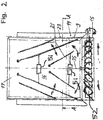
- the width adjustment device 50 may have guide strips 21, which are arranged on the inner side 16 of the discharge flap 13 and extend - roughly speaking - along the discharge flap from top to bottom.
- the aforementioned guide rails 21 are variable in their angle of attack and stored correspondingly adjustable, for example, pivotally mounted about pivot axes at their upper ends.
- the angle of attack of the guide rails 21 is adjustable by Stellaktoren 51, by which the guide rails 21 are more or less strongly als als als als als als als als als als als als als als als als als als als als als als als als,sp Dahlbar.
- the Stellaktoren 51 which may include, for example, pressure cylinder or electric motors, so that increases the distance of the guide rails from top to bottom on the unloading flap, see.
- Fig. 2 Conversely, the guide rails 21 could also be spread to a standing V to collapse the crop into a narrower carpet.
- the actuators 51 may be actuated by a discharge control device 100 to position the guide rails accordingly
- the unloading control device 100 may be a job computer provided on the harvest car 1 itself.
- the unloading control device 100 may also be implemented on the tractor pulling the unloading cart 1.
- the width adjustment device 50 can have at least one transverse conveyor 52, for example in the form of a screw conveyor, which can be arranged on a lower end section of the unloading flap 13 and / or under or on the loading compartment floor 5b. It is also possible for a plurality of such transverse conveyors 52, for example in the form of screw conveyors, to be distributed one above the other on the inside of the unloading flap 13 or to be distributed at the discharge edge of the loading floor 5b.
- such a transverse conveyor 52 can also project between an active position below the loading compartment floor 5b and an active position in which the transverse conveyor 52 protrudes beyond the discharge edge and / or protrudes above the outline contour of the loading compartment floor 5b in a top view of the harvesting vehicle from above and / or in terms of height overlaps with the load compartment floor 5b, be supported reciprocally.
- the transverse conveyor 52 may be mounted displaceably under the load compartment floor 5b, in order to be able to be moved back and forth between said inactive position and the active position.
- the cross conveyor 52 but also be pivotally arranged on the load compartment floor 5b, in particular to be pivoted away under the load compartment floor and vice versa to be swung out into the active position can.
- the cross conveyor 52 may also be formed as Rechnikeliki with circumferentially driven rotary rakes, which may for example circulate about an approximately upright gyro axis, here advantageously several such rotary rake can be arranged distributed along the discharge edge.
- a plurality of rotary rakes can be driven individually or in groups in different directions of rotation in order to move the unloaded crop farther outwards or further inwards.
- rotary rakes can be used as a transverse conveyor but also a conveyor belt or a plurality of conveyor belts or a roller or roller conveyor with drivable rollers use.
- transverse conveyor 52 under or on the loading space floor 5b is also possible for the transverse screw conveyors already described.
- the discharge flap 13 may be formed in itself adjustable and have a plurality of mutually adjustable, in particular pivotable flap sections.
- a lower end section 15 of the discharge flap 13 can be pivotable about a horizontal transverse axis relative to an overlying flap section, wherein a Stellaktor 35 may be provided to pivot the flap parts to each other, in particular to pivot the lower end portion 15.
- said cross conveyor 52 may be mounted, wherein the cross conveyor 52 may comprise two screw parts which promote each other in opposite directions and depending on the direction of rotation together promote the crop to a narrower carpet or a wider carpet pull apart.
- the transverse conveying drive of the transverse conveyor 52 can also be controlled by the unloading control device 100 in order to be able to vary the transverse conveying speed and thereby be able to change the carpet width or the transverse conveying effect.
- Said unloading control device 100 can also control the position of the discharge flap 13, in particular its Aufschwenkwinkel during unloading.
- the discharge control device 100 can also control the Stellaktor 35 to vary the pivot angle of the lower end portion 15 and thus the position of the transverse conveyor 52.
- the unloading control device 100 can also control the discharge feed speed of the unloading conveyor 6 in the form of the scraper floor and / or the metering rollers and specify an unloading feed signal for this purpose and advantageously also predefine a travel speed signal by means of which the tractor driver or the tractor himself can automatically control the travel speed.
- the unloading control device 100 comprises input means, for example in the form of a touchscreen 110, to be able to enter relevant unloading parameters, in particular a drive-line length or the length of the travel path through the travel silo and / or a desired crop carpet thickness and / or a desired crop carpet width.
- the harvested goods vehicle 1 can have a detection device 120 for detecting the loaded or unloaded crop quantity.
- This detection device 120 may include a level sensor and / or a weight sensor and provide the amount of crop in the hold 5 to the discharge control device 100 or provide retrievable.
- the harvested goods vehicle 1 can have a further detection device 130, which makes the unloaded crop carpet more relevant Carpet parameters detected, in particular the carpet thickness and the carpet width, said detection device 130 arranged on the rear side of the crop wagon and / or observe the unloading area to provide actual values of the relevant carpet parameters.
- the unloading control device 100 may control the crop cart during unloading in various automatic stages or automatic modes. For example, in the manner mentioned in a teach-in process, a skilled tractor operator can manually control the unloading process, the unloading control apparatus 100 determining the relevant unloading parameters, in particular the scraper floor speed, the tractor's travel speed, the discharge flap position, the guide rail angles, the position of the cross conveyor in the form of the folding angle of the lower end portion of the unloading door and the lateral conveying speed are detected and stored. The detection can be carried out continuously over the route through the silo or even selectively at predetermined intervals.
- the discharge control device 100 may automatically control some or all of the aforementioned unloading parameters, in particular providing the scraper floor speed and the settings of the width distribution device as well as the position of the tailgate and possibly also a vehicle speed signal.
- setpoint signals can be preset for all or part of the aforementioned control variables and displayed on display means, by means of which a machine operator can then control the unloading process.
- relevant unloading variables such as ride length, desired carpet thickness, and desired carpet width can be selected via the touch screen 110 or other suitable input means, with the unload control device 100 selecting some or all of the other relevant adjustable ones from the preselected sizes Calculates unloading parameters, in particular the scraper floor speed, the tailgate position and the settings of the width distribution device such as For example, the conveying speed of the cross conveyor 52.
- a vehicle speed signal can be calculated and provided.
- the unloading control device 100 can again take into account the amount of crop that was detected by the detection device 120 or, if appropriate, can also be entered manually, for example in the form of a filling level of the loading space.
- Discharge control device 100 may further include a controller 140 that controls some or all of the aforementioned discharge parameters in response to a desired-actual-value comparison.
- the actual values of the carpet thickness and / or the width of the carpet detected by the detection device 130 can be compared with predetermined desired values for the carpet thickness and / or the carpet width.
- the controller 140 then regulates depending on the specified target-actual value comparison, in particular the Entladevorschubissus the unloading conveyor 6 and / or the variable parameters of Pope 50, for example, the spread angle of the guide rails 21 and the conveying speed of the transverse conveyor 52 and / or the Entladeklappengnagnagnagnagnagnagnagnagnagnagnagnagnagnat and / or the speed of the tractor.
Landscapes
- Life Sciences & Earth Sciences (AREA)
- Environmental Sciences (AREA)
- Harvesting Machines For Root Crops (AREA)
- Harvester Elements (AREA)
Applications Claiming Priority (2)
| Application Number | Priority Date | Filing Date | Title |
|---|---|---|---|
| DE102016015517 | 2016-12-23 | ||
| DE102017004181 | 2017-04-28 |
Publications (2)
| Publication Number | Publication Date |
|---|---|
| EP3338532A1 true EP3338532A1 (fr) | 2018-06-27 |
| EP3338532B1 EP3338532B1 (fr) | 2020-03-04 |
Family
ID=60674015
Family Applications (1)
| Application Number | Title | Priority Date | Filing Date |
|---|---|---|---|
| EP17208527.6A Active EP3338532B1 (fr) | 2016-12-23 | 2017-12-19 | Engin de récolte agricole ainsi que procédé de déchargement d'un tel engin de récolte |
Country Status (2)
| Country | Link |
|---|---|
| EP (1) | EP3338532B1 (fr) |
| DE (1) | DE102017130999A1 (fr) |
Cited By (1)
| Publication number | Priority date | Publication date | Assignee | Title |
|---|---|---|---|---|
| EP3403488A1 (fr) * | 2017-05-19 | 2018-11-21 | Deere & Company | Procédé et machine de travail agricole destinée à l'épandage de produit de la récolte |
Citations (5)
| Publication number | Priority date | Publication date | Assignee | Title |
|---|---|---|---|---|
| DE3232905A1 (de) * | 1982-09-04 | 1984-03-08 | Ernst 7326 Heiningen Weichel | Verfahren und vorrichtung zum aufladen, zerkleinern, transportieren und dosierten entladen landwirtschaftlicher massengueter |
| DE19612053A1 (de) * | 1996-03-27 | 1997-10-02 | Erwin Schluetter | Vorrichtung zum Ernten von Häckselgütern, insbesondere Mais oder Gras |
| DE19704457A1 (de) * | 1997-02-06 | 1998-08-13 | Mengele & Soehne Masch Karl | Entladeeinrichtung für landwirtschaftliche Fahrzeuge |
| DE202012006091U1 (de) * | 2012-06-22 | 2013-09-24 | Alois Pöttinger Maschinenfabrik Ges.m.b.H. | Landwirtschaftliche Erntemaschine |
| EP3078256A1 (fr) | 2015-04-09 | 2016-10-12 | B. Strautmann & Söhne GmbH u. Co. KG, | Chariot de recolte comprenant un appareil de dosage et d'epandage |
-
2017
- 2017-12-19 EP EP17208527.6A patent/EP3338532B1/fr active Active
- 2017-12-21 DE DE102017130999.3A patent/DE102017130999A1/de not_active Withdrawn
Patent Citations (5)
| Publication number | Priority date | Publication date | Assignee | Title |
|---|---|---|---|---|
| DE3232905A1 (de) * | 1982-09-04 | 1984-03-08 | Ernst 7326 Heiningen Weichel | Verfahren und vorrichtung zum aufladen, zerkleinern, transportieren und dosierten entladen landwirtschaftlicher massengueter |
| DE19612053A1 (de) * | 1996-03-27 | 1997-10-02 | Erwin Schluetter | Vorrichtung zum Ernten von Häckselgütern, insbesondere Mais oder Gras |
| DE19704457A1 (de) * | 1997-02-06 | 1998-08-13 | Mengele & Soehne Masch Karl | Entladeeinrichtung für landwirtschaftliche Fahrzeuge |
| DE202012006091U1 (de) * | 2012-06-22 | 2013-09-24 | Alois Pöttinger Maschinenfabrik Ges.m.b.H. | Landwirtschaftliche Erntemaschine |
| EP3078256A1 (fr) | 2015-04-09 | 2016-10-12 | B. Strautmann & Söhne GmbH u. Co. KG, | Chariot de recolte comprenant un appareil de dosage et d'epandage |
Cited By (3)
| Publication number | Priority date | Publication date | Assignee | Title |
|---|---|---|---|---|
| EP3403488A1 (fr) * | 2017-05-19 | 2018-11-21 | Deere & Company | Procédé et machine de travail agricole destinée à l'épandage de produit de la récolte |
| EP3563667A1 (fr) | 2017-05-19 | 2019-11-06 | Deere & Company | Procédé et machine de travail agricole destinée à l'épandage de la récolte |
| US10617054B2 (en) | 2017-05-19 | 2020-04-14 | Deere & Company | Method and agricultural utility machine for spreading crop |
Also Published As
| Publication number | Publication date |
|---|---|
| DE102017130999A1 (de) | 2018-06-28 |
| EP3338532B1 (fr) | 2020-03-04 |
Similar Documents
| Publication | Publication Date | Title |
|---|---|---|
| EP3593620B1 (fr) | Système de récolte | |
| DE3872987T2 (de) | Verfahren und vorrichtung zum herstellen von bituminoesen strassendecken. | |
| EP2829171B1 (fr) | Moissonneuse automotrice et véhicule associé | |
| DE68923607T2 (de) | Verfahren und Vorrichtung zum Herstellen von bituminösen Strassendecken. | |
| EP2840183B1 (fr) | Engin autopropulsé et procédé de fonctionnement d'un engin automoteur | |
| EP1982575B1 (fr) | Presse à empaqueter fonctionnant en continu | |
| EP3000302A1 (fr) | Moissonneuse-batteuse equipee d'un dispositif de distribution | |
| DE102011000057A1 (de) | Mähdrescher mit einer Verteilvorrichtung zur Verteilung gehäckselten Erntegutes | |
| EP2510777A1 (fr) | Procédé de réglage d'une installation de nettoyage d'une moissonneuse-batteuse et installation de nettoyage | |
| CH639162A5 (de) | Selbstfahrbare gleisbett-reinigungsmaschine. | |
| EP1645178A1 (fr) | Système d'assistance pour le transfert | |
| EP2048096A1 (fr) | Convoyeur de bagages | |
| EP3338531A1 (fr) | Engin de récolte agricole ainsi que procédé de déchargement d'un tel engin de récolte | |
| EP2745671B1 (fr) | Assemblage de convoyeur incliné doté d'un fond flexible | |
| DE102011053163A1 (de) | System zur Steuerung einer Überladeeinrichtung | |
| EP3338532B1 (fr) | Engin de récolte agricole ainsi que procédé de déchargement d'un tel engin de récolte | |
| EP3603376B1 (fr) | Machine de récolte doté d'une tête de récolte et d'une roue d'appui | |
| EP3489415B1 (fr) | Machine de fraisage autopropulsée et procédé de chargement automatique d'un moyen de transport avec du matériau fraisé | |
| DE102013005842B4 (de) | Landwirtschaftliche Erntemaschine | |
| EP4066614A1 (fr) | Véhicule d'épandage pourvu de fond mouvant divisé et de régulation de vitesse | |
| EP3771324A1 (fr) | Remorque pour chargement de fourrage et/ou de hachage | |
| DE102011110878A1 (de) | Landwirtschaftlicher Transportwagen | |
| DE102017011159A1 (de) | Straßenbaumaschine und Verfahren zum Betreiben einer Straßenbaumaschine | |
| DE202019100440U1 (de) | Landwirtschaftlicher Erntegutwagen | |
| EP4646914A1 (fr) | Procédé de fonctionnement d'un appareil auxiliaire disposé sur un dispositif de réception d'une moissonneuse-batteuse ainsi que moissonneuse-batteuse automotrice |
Legal Events
| Date | Code | Title | Description |
|---|---|---|---|
| PUAI | Public reference made under article 153(3) epc to a published international application that has entered the european phase |
Free format text: ORIGINAL CODE: 0009012 |
|
| STAA | Information on the status of an ep patent application or granted ep patent |
Free format text: STATUS: THE APPLICATION HAS BEEN PUBLISHED |
|
| STAA | Information on the status of an ep patent application or granted ep patent |
Free format text: STATUS: REQUEST FOR EXAMINATION WAS MADE |
|
| AK | Designated contracting states |
Kind code of ref document: A1 Designated state(s): AL AT BE BG CH CY CZ DE DK EE ES FI FR GB GR HR HU IE IS IT LI LT LU LV MC MK MT NL NO PL PT RO RS SE SI SK SM TR |
|
| AX | Request for extension of the european patent |
Extension state: BA ME |
|
| 17P | Request for examination filed |
Effective date: 20180614 |
|
| RBV | Designated contracting states (corrected) |
Designated state(s): AL AT BE BG CH CY CZ DE DK EE ES FI FR GB GR HR HU IE IS IT LI LT LU LV MC MK MT NL NO PL PT RO RS SE SI SK SM TR |
|
| STAA | Information on the status of an ep patent application or granted ep patent |
Free format text: STATUS: EXAMINATION IS IN PROGRESS |
|
| 17Q | First examination report despatched |
Effective date: 20181019 |
|
| RIC1 | Information provided on ipc code assigned before grant |
Ipc: A01D 90/10 20060101AFI20190801BHEP Ipc: A01C 3/06 20060101ALN20190801BHEP Ipc: A01F 25/18 20060101ALI20190801BHEP |
|
| GRAP | Despatch of communication of intention to grant a patent |
Free format text: ORIGINAL CODE: EPIDOSNIGR1 |
|
| STAA | Information on the status of an ep patent application or granted ep patent |
Free format text: STATUS: GRANT OF PATENT IS INTENDED |
|
| INTG | Intention to grant announced |
Effective date: 20190923 |
|
| GRAS | Grant fee paid |
Free format text: ORIGINAL CODE: EPIDOSNIGR3 |
|
| GRAA | (expected) grant |
Free format text: ORIGINAL CODE: 0009210 |
|
| STAA | Information on the status of an ep patent application or granted ep patent |
Free format text: STATUS: THE PATENT HAS BEEN GRANTED |
|
| AK | Designated contracting states |
Kind code of ref document: B1 Designated state(s): AL AT BE BG CH CY CZ DE DK EE ES FI FR GB GR HR HU IE IS IT LI LT LU LV MC MK MT NL NO PL PT RO RS SE SI SK SM TR |
|
| REG | Reference to a national code |
Ref country code: GB Ref legal event code: FG4D Free format text: NOT ENGLISH |
|
| REG | Reference to a national code |
Ref country code: CH Ref legal event code: EP |
|
| REG | Reference to a national code |
Ref country code: AT Ref legal event code: REF Ref document number: 1239339 Country of ref document: AT Kind code of ref document: T Effective date: 20200315 |
|
| REG | Reference to a national code |
Ref country code: DE Ref legal event code: R096 Ref document number: 502017004082 Country of ref document: DE |
|
| REG | Reference to a national code |
Ref country code: IE Ref legal event code: FG4D Free format text: LANGUAGE OF EP DOCUMENT: GERMAN |
|
| REG | Reference to a national code |
Ref country code: NL Ref legal event code: FP |
|
| PG25 | Lapsed in a contracting state [announced via postgrant information from national office to epo] |
Ref country code: NO Free format text: LAPSE BECAUSE OF FAILURE TO SUBMIT A TRANSLATION OF THE DESCRIPTION OR TO PAY THE FEE WITHIN THE PRESCRIBED TIME-LIMIT Effective date: 20200604 Ref country code: RS Free format text: LAPSE BECAUSE OF FAILURE TO SUBMIT A TRANSLATION OF THE DESCRIPTION OR TO PAY THE FEE WITHIN THE PRESCRIBED TIME-LIMIT Effective date: 20200304 Ref country code: FI Free format text: LAPSE BECAUSE OF FAILURE TO SUBMIT A TRANSLATION OF THE DESCRIPTION OR TO PAY THE FEE WITHIN THE PRESCRIBED TIME-LIMIT Effective date: 20200304 |
|
| PG25 | Lapsed in a contracting state [announced via postgrant information from national office to epo] |
Ref country code: LV Free format text: LAPSE BECAUSE OF FAILURE TO SUBMIT A TRANSLATION OF THE DESCRIPTION OR TO PAY THE FEE WITHIN THE PRESCRIBED TIME-LIMIT Effective date: 20200304 Ref country code: SE Free format text: LAPSE BECAUSE OF FAILURE TO SUBMIT A TRANSLATION OF THE DESCRIPTION OR TO PAY THE FEE WITHIN THE PRESCRIBED TIME-LIMIT Effective date: 20200304 Ref country code: GR Free format text: LAPSE BECAUSE OF FAILURE TO SUBMIT A TRANSLATION OF THE DESCRIPTION OR TO PAY THE FEE WITHIN THE PRESCRIBED TIME-LIMIT Effective date: 20200605 Ref country code: BG Free format text: LAPSE BECAUSE OF FAILURE TO SUBMIT A TRANSLATION OF THE DESCRIPTION OR TO PAY THE FEE WITHIN THE PRESCRIBED TIME-LIMIT Effective date: 20200604 Ref country code: HR Free format text: LAPSE BECAUSE OF FAILURE TO SUBMIT A TRANSLATION OF THE DESCRIPTION OR TO PAY THE FEE WITHIN THE PRESCRIBED TIME-LIMIT Effective date: 20200304 |
|
| REG | Reference to a national code |
Ref country code: LT Ref legal event code: MG4D |
|
| PG25 | Lapsed in a contracting state [announced via postgrant information from national office to epo] |
Ref country code: ES Free format text: LAPSE BECAUSE OF FAILURE TO SUBMIT A TRANSLATION OF THE DESCRIPTION OR TO PAY THE FEE WITHIN THE PRESCRIBED TIME-LIMIT Effective date: 20200304 Ref country code: LT Free format text: LAPSE BECAUSE OF FAILURE TO SUBMIT A TRANSLATION OF THE DESCRIPTION OR TO PAY THE FEE WITHIN THE PRESCRIBED TIME-LIMIT Effective date: 20200304 Ref country code: EE Free format text: LAPSE BECAUSE OF FAILURE TO SUBMIT A TRANSLATION OF THE DESCRIPTION OR TO PAY THE FEE WITHIN THE PRESCRIBED TIME-LIMIT Effective date: 20200304 Ref country code: SM Free format text: LAPSE BECAUSE OF FAILURE TO SUBMIT A TRANSLATION OF THE DESCRIPTION OR TO PAY THE FEE WITHIN THE PRESCRIBED TIME-LIMIT Effective date: 20200304 Ref country code: PT Free format text: LAPSE BECAUSE OF FAILURE TO SUBMIT A TRANSLATION OF THE DESCRIPTION OR TO PAY THE FEE WITHIN THE PRESCRIBED TIME-LIMIT Effective date: 20200729 Ref country code: IS Free format text: LAPSE BECAUSE OF FAILURE TO SUBMIT A TRANSLATION OF THE DESCRIPTION OR TO PAY THE FEE WITHIN THE PRESCRIBED TIME-LIMIT Effective date: 20200704 Ref country code: SK Free format text: LAPSE BECAUSE OF FAILURE TO SUBMIT A TRANSLATION OF THE DESCRIPTION OR TO PAY THE FEE WITHIN THE PRESCRIBED TIME-LIMIT Effective date: 20200304 Ref country code: RO Free format text: LAPSE BECAUSE OF FAILURE TO SUBMIT A TRANSLATION OF THE DESCRIPTION OR TO PAY THE FEE WITHIN THE PRESCRIBED TIME-LIMIT Effective date: 20200304 Ref country code: CZ Free format text: LAPSE BECAUSE OF FAILURE TO SUBMIT A TRANSLATION OF THE DESCRIPTION OR TO PAY THE FEE WITHIN THE PRESCRIBED TIME-LIMIT Effective date: 20200304 |
|
| REG | Reference to a national code |
Ref country code: DE Ref legal event code: R097 Ref document number: 502017004082 Country of ref document: DE |
|
| PLBE | No opposition filed within time limit |
Free format text: ORIGINAL CODE: 0009261 |
|
| STAA | Information on the status of an ep patent application or granted ep patent |
Free format text: STATUS: NO OPPOSITION FILED WITHIN TIME LIMIT |
|
| PG25 | Lapsed in a contracting state [announced via postgrant information from national office to epo] |
Ref country code: IT Free format text: LAPSE BECAUSE OF FAILURE TO SUBMIT A TRANSLATION OF THE DESCRIPTION OR TO PAY THE FEE WITHIN THE PRESCRIBED TIME-LIMIT Effective date: 20200304 Ref country code: DK Free format text: LAPSE BECAUSE OF FAILURE TO SUBMIT A TRANSLATION OF THE DESCRIPTION OR TO PAY THE FEE WITHIN THE PRESCRIBED TIME-LIMIT Effective date: 20200304 |
|
| 26N | No opposition filed |
Effective date: 20201207 |
|
| PG25 | Lapsed in a contracting state [announced via postgrant information from national office to epo] |
Ref country code: SI Free format text: LAPSE BECAUSE OF FAILURE TO SUBMIT A TRANSLATION OF THE DESCRIPTION OR TO PAY THE FEE WITHIN THE PRESCRIBED TIME-LIMIT Effective date: 20200304 Ref country code: PL Free format text: LAPSE BECAUSE OF FAILURE TO SUBMIT A TRANSLATION OF THE DESCRIPTION OR TO PAY THE FEE WITHIN THE PRESCRIBED TIME-LIMIT Effective date: 20200304 |
|
| REG | Reference to a national code |
Ref country code: CH Ref legal event code: PL |
|
| PG25 | Lapsed in a contracting state [announced via postgrant information from national office to epo] |
Ref country code: MC Free format text: LAPSE BECAUSE OF FAILURE TO SUBMIT A TRANSLATION OF THE DESCRIPTION OR TO PAY THE FEE WITHIN THE PRESCRIBED TIME-LIMIT Effective date: 20200304 |
|
| REG | Reference to a national code |
Ref country code: BE Ref legal event code: MM Effective date: 20201231 |
|
| PG25 | Lapsed in a contracting state [announced via postgrant information from national office to epo] |
Ref country code: IE Free format text: LAPSE BECAUSE OF NON-PAYMENT OF DUE FEES Effective date: 20201219 Ref country code: FR Free format text: LAPSE BECAUSE OF NON-PAYMENT OF DUE FEES Effective date: 20201231 Ref country code: LU Free format text: LAPSE BECAUSE OF NON-PAYMENT OF DUE FEES Effective date: 20201219 |
|
| PG25 | Lapsed in a contracting state [announced via postgrant information from national office to epo] |
Ref country code: CH Free format text: LAPSE BECAUSE OF NON-PAYMENT OF DUE FEES Effective date: 20201231 Ref country code: LI Free format text: LAPSE BECAUSE OF NON-PAYMENT OF DUE FEES Effective date: 20201231 |
|
| PG25 | Lapsed in a contracting state [announced via postgrant information from national office to epo] |
Ref country code: TR Free format text: LAPSE BECAUSE OF FAILURE TO SUBMIT A TRANSLATION OF THE DESCRIPTION OR TO PAY THE FEE WITHIN THE PRESCRIBED TIME-LIMIT Effective date: 20200304 Ref country code: MT Free format text: LAPSE BECAUSE OF FAILURE TO SUBMIT A TRANSLATION OF THE DESCRIPTION OR TO PAY THE FEE WITHIN THE PRESCRIBED TIME-LIMIT Effective date: 20200304 Ref country code: CY Free format text: LAPSE BECAUSE OF FAILURE TO SUBMIT A TRANSLATION OF THE DESCRIPTION OR TO PAY THE FEE WITHIN THE PRESCRIBED TIME-LIMIT Effective date: 20200304 |
|
| PG25 | Lapsed in a contracting state [announced via postgrant information from national office to epo] |
Ref country code: MK Free format text: LAPSE BECAUSE OF FAILURE TO SUBMIT A TRANSLATION OF THE DESCRIPTION OR TO PAY THE FEE WITHIN THE PRESCRIBED TIME-LIMIT Effective date: 20200304 Ref country code: AL Free format text: LAPSE BECAUSE OF FAILURE TO SUBMIT A TRANSLATION OF THE DESCRIPTION OR TO PAY THE FEE WITHIN THE PRESCRIBED TIME-LIMIT Effective date: 20200304 |
|
| PG25 | Lapsed in a contracting state [announced via postgrant information from national office to epo] |
Ref country code: BE Free format text: LAPSE BECAUSE OF NON-PAYMENT OF DUE FEES Effective date: 20201231 |
|
| GBPC | Gb: european patent ceased through non-payment of renewal fee |
Effective date: 20211219 |
|
| PG25 | Lapsed in a contracting state [announced via postgrant information from national office to epo] |
Ref country code: GB Free format text: LAPSE BECAUSE OF NON-PAYMENT OF DUE FEES Effective date: 20211219 |
|
| P01 | Opt-out of the competence of the unified patent court (upc) registered |
Effective date: 20230613 |
|
| PGFP | Annual fee paid to national office [announced via postgrant information from national office to epo] |
Ref country code: NL Payment date: 20231124 Year of fee payment: 7 |
|
| PGFP | Annual fee paid to national office [announced via postgrant information from national office to epo] |
Ref country code: DE Payment date: 20231107 Year of fee payment: 7 |
|
| REG | Reference to a national code |
Ref country code: AT Ref legal event code: MM01 Ref document number: 1239339 Country of ref document: AT Kind code of ref document: T Effective date: 20221219 |
|
| PG25 | Lapsed in a contracting state [announced via postgrant information from national office to epo] |
Ref country code: AT Free format text: LAPSE BECAUSE OF NON-PAYMENT OF DUE FEES Effective date: 20221219 |
|
| PG25 | Lapsed in a contracting state [announced via postgrant information from national office to epo] |
Ref country code: AT Free format text: LAPSE BECAUSE OF NON-PAYMENT OF DUE FEES Effective date: 20221219 |
|
| REG | Reference to a national code |
Ref country code: DE Ref legal event code: R119 Ref document number: 502017004082 Country of ref document: DE |
|
| REG | Reference to a national code |
Ref country code: NL Ref legal event code: MM Effective date: 20250101 |
|
| PG25 | Lapsed in a contracting state [announced via postgrant information from national office to epo] |
Ref country code: NL Free format text: LAPSE BECAUSE OF NON-PAYMENT OF DUE FEES Effective date: 20250101 |
|
| PG25 | Lapsed in a contracting state [announced via postgrant information from national office to epo] |
Ref country code: DE Free format text: LAPSE BECAUSE OF NON-PAYMENT OF DUE FEES Effective date: 20250701 |
|
| PGFP | Annual fee paid to national office [announced via postgrant information from national office to epo] |
Ref country code: AT Payment date: 20260410 Year of fee payment: 5 |