EP3338731A1 - Insert dentaire destiné à relier un implant dentaire à un support dentaire - Google Patents
Insert dentaire destiné à relier un implant dentaire à un support dentaire Download PDFInfo
- Publication number
- EP3338731A1 EP3338731A1 EP16206721.9A EP16206721A EP3338731A1 EP 3338731 A1 EP3338731 A1 EP 3338731A1 EP 16206721 A EP16206721 A EP 16206721A EP 3338731 A1 EP3338731 A1 EP 3338731A1
- Authority
- EP
- European Patent Office
- Prior art keywords
- dental
- cap
- attachment
- implant
- insert
- Prior art date
- Legal status (The legal status is an assumption and is not a legal conclusion. Google has not performed a legal analysis and makes no representation as to the accuracy of the status listed.)
- Withdrawn
Links
- 239000004053 dental implant Substances 0.000 title claims abstract description 9
- 239000007943 implant Substances 0.000 claims abstract description 45
- 238000003780 insertion Methods 0.000 claims description 26
- 230000037431 insertion Effects 0.000 claims description 26
- 239000000463 material Substances 0.000 claims description 20
- 239000003242 anti bacterial agent Substances 0.000 claims description 3
- 230000000844 anti-bacterial effect Effects 0.000 claims description 3
- 239000002260 anti-inflammatory agent Substances 0.000 claims description 3
- 229940121363 anti-inflammatory agent Drugs 0.000 claims description 3
- 229920001643 poly(ether ketone) Polymers 0.000 claims description 3
- 239000000645 desinfectant Substances 0.000 claims description 2
- 230000000249 desinfective effect Effects 0.000 claims description 2
- 238000004382 potting Methods 0.000 description 9
- 150000001875 compounds Chemical class 0.000 description 8
- 210000003128 head Anatomy 0.000 description 5
- 230000008719 thickening Effects 0.000 description 5
- 230000002787 reinforcement Effects 0.000 description 4
- 239000004696 Poly ether ether ketone Substances 0.000 description 3
- 239000004480 active ingredient Substances 0.000 description 3
- 238000004519 manufacturing process Methods 0.000 description 3
- 229920002530 polyetherether ketone Polymers 0.000 description 3
- MCMNRKCIXSYSNV-UHFFFAOYSA-N Zirconium dioxide Chemical compound O=[Zr]=O MCMNRKCIXSYSNV-UHFFFAOYSA-N 0.000 description 2
- 239000004033 plastic Substances 0.000 description 2
- 210000000332 tooth crown Anatomy 0.000 description 2
- 230000003313 weakening effect Effects 0.000 description 2
- PAYROHWFGZADBR-UHFFFAOYSA-N 2-[[4-amino-5-(5-iodo-4-methoxy-2-propan-2-ylphenoxy)pyrimidin-2-yl]amino]propane-1,3-diol Chemical compound C1=C(I)C(OC)=CC(C(C)C)=C1OC1=CN=C(NC(CO)CO)N=C1N PAYROHWFGZADBR-UHFFFAOYSA-N 0.000 description 1
- RTAQQCXQSZGOHL-UHFFFAOYSA-N Titanium Chemical compound [Ti] RTAQQCXQSZGOHL-UHFFFAOYSA-N 0.000 description 1
- 238000009825 accumulation Methods 0.000 description 1
- 239000000853 adhesive Substances 0.000 description 1
- 230000001070 adhesive effect Effects 0.000 description 1
- 239000004599 antimicrobial Substances 0.000 description 1
- JUPQTSLXMOCDHR-UHFFFAOYSA-N benzene-1,4-diol;bis(4-fluorophenyl)methanone Chemical compound OC1=CC=C(O)C=C1.C1=CC(F)=CC=C1C(=O)C1=CC=C(F)C=C1 JUPQTSLXMOCDHR-UHFFFAOYSA-N 0.000 description 1
- 239000004568 cement Substances 0.000 description 1
- 239000000919 ceramic Substances 0.000 description 1
- 229910010293 ceramic material Inorganic materials 0.000 description 1
- 230000008859 change Effects 0.000 description 1
- 238000011109 contamination Methods 0.000 description 1
- 230000008878 coupling Effects 0.000 description 1
- 238000010168 coupling process Methods 0.000 description 1
- 238000005859 coupling reaction Methods 0.000 description 1
- 230000001419 dependent effect Effects 0.000 description 1
- 201000010099 disease Diseases 0.000 description 1
- 208000037265 diseases, disorders, signs and symptoms Diseases 0.000 description 1
- 238000009826 distribution Methods 0.000 description 1
- 238000005553 drilling Methods 0.000 description 1
- 230000000694 effects Effects 0.000 description 1
- 239000011521 glass Substances 0.000 description 1
- PCHJSUWPFVWCPO-UHFFFAOYSA-N gold Chemical compound [Au] PCHJSUWPFVWCPO-UHFFFAOYSA-N 0.000 description 1
- 229910052737 gold Inorganic materials 0.000 description 1
- 239000010931 gold Substances 0.000 description 1
- 238000001746 injection moulding Methods 0.000 description 1
- 230000003993 interaction Effects 0.000 description 1
- 210000001331 nose Anatomy 0.000 description 1
- 229920001652 poly(etherketoneketone) Polymers 0.000 description 1
- 229920000642 polymer Polymers 0.000 description 1
- 229940100890 silver compound Drugs 0.000 description 1
- 150000003379 silver compounds Chemical class 0.000 description 1
- 229910052719 titanium Inorganic materials 0.000 description 1
- 239000010936 titanium Substances 0.000 description 1
Images



Classifications
-
- A—HUMAN NECESSITIES
- A61—MEDICAL OR VETERINARY SCIENCE; HYGIENE
- A61C—DENTISTRY; APPARATUS OR METHODS FOR ORAL OR DENTAL HYGIENE
- A61C8/00—Means to be fixed to the jaw-bone for consolidating natural teeth or for fixing dental prostheses thereon; Dental implants; Implanting tools
- A61C8/0048—Connecting the upper structure to the implant, e.g. bridging bars
- A61C8/005—Connecting devices for joining an upper structure with an implant member, e.g. spacers
- A61C8/0062—Catch or snap type connection
-
- A—HUMAN NECESSITIES
- A61—MEDICAL OR VETERINARY SCIENCE; HYGIENE
- A61C—DENTISTRY; APPARATUS OR METHODS FOR ORAL OR DENTAL HYGIENE
- A61C8/00—Means to be fixed to the jaw-bone for consolidating natural teeth or for fixing dental prostheses thereon; Dental implants; Implanting tools
- A61C8/0048—Connecting the upper structure to the implant, e.g. bridging bars
- A61C8/005—Connecting devices for joining an upper structure with an implant member, e.g. spacers
- A61C8/0063—Connecting devices for joining an upper structure with an implant member, e.g. spacers with an internal sleeve
-
- A—HUMAN NECESSITIES
- A61—MEDICAL OR VETERINARY SCIENCE; HYGIENE
- A61C—DENTISTRY; APPARATUS OR METHODS FOR ORAL OR DENTAL HYGIENE
- A61C8/00—Means to be fixed to the jaw-bone for consolidating natural teeth or for fixing dental prostheses thereon; Dental implants; Implanting tools
- A61C8/0048—Connecting the upper structure to the implant, e.g. bridging bars
- A61C8/005—Connecting devices for joining an upper structure with an implant member, e.g. spacers
- A61C8/0065—Connecting devices for joining an upper structure with an implant member, e.g. spacers with expandable or compressible means
-
- A—HUMAN NECESSITIES
- A61—MEDICAL OR VETERINARY SCIENCE; HYGIENE
- A61C—DENTISTRY; APPARATUS OR METHODS FOR ORAL OR DENTAL HYGIENE
- A61C8/00—Means to be fixed to the jaw-bone for consolidating natural teeth or for fixing dental prostheses thereon; Dental implants; Implanting tools
- A61C8/0048—Connecting the upper structure to the implant, e.g. bridging bars
- A61C8/005—Connecting devices for joining an upper structure with an implant member, e.g. spacers
- A61C8/0054—Connecting devices for joining an upper structure with an implant member, e.g. spacers having a cylindrical implant connecting part
-
- A—HUMAN NECESSITIES
- A61—MEDICAL OR VETERINARY SCIENCE; HYGIENE
- A61C—DENTISTRY; APPARATUS OR METHODS FOR ORAL OR DENTAL HYGIENE
- A61C8/00—Means to be fixed to the jaw-bone for consolidating natural teeth or for fixing dental prostheses thereon; Dental implants; Implanting tools
- A61C8/0048—Connecting the upper structure to the implant, e.g. bridging bars
- A61C8/005—Connecting devices for joining an upper structure with an implant member, e.g. spacers
- A61C8/0068—Connecting devices for joining an upper structure with an implant member, e.g. spacers with an additional screw
Definitions
- the present invention relates to a dental insert for connecting a dental implant with a dental attachment, as well as an arrangement of the dental insert with the dental attachment and a dental prosthesis.
- the invention solves this problem by a dental use for the connection of a dental implant with a dental attachment with the features of claim 1, and an arrangement with the features of claim 8 and a dental prosthesis with the features of claim 15.
- a dental insert for connecting a dental implant with a dental attachment.
- a corresponding attachment may preferably be designed as a tooth crown or a so-called abutment.
- This dental insert has at least two interfaces.
- a first interface is formed in cooperation with the attachment for fixing the dental insert with the implant by at least one latching and / or clamping connection.
- This first interface can have, for example, a receptacle with latching noses or the like into which a projection of the implant can be inserted.
- the receiving wall can then by the connection of the dental insert with the dental attachment material reinforcement so that the attachment with the implant is positively determined by locking or jamming.
- the second interface is designed for fixing the attachment. This can preferably be done by screwing.
- a screw and a screw within the meaning of the present invention are u.a. Also bayonet connections, so that two elements by a rotary motion analogous to a conventional screw are engaged with each other.
- the dental insert can be advantageously designed as a plug cap with a cap opening, a cap base and a cap skirt surface.
- the cap base is not necessarily a closed surface but it can advantageously have recesses.
- the cap base advantageously has as the first of the at least two interfaces a receptacle with a receiving space for attaching to a projection of the implant.
- the receptacle may advantageously have an area for receiving a projection thickening and an adjacent area with a cross-sectional constriction of the receptacle.
- the insertion cap may have a longitudinal axis, wherein the receptacle is advantageously arranged centered on the longitudinal axis.
- the receptacle may have a receiving wall which limits the receiving space, wherein adjacent to the receiving wall a cap space extends in which the attachment is partially inserted.
- the receiving wall may advantageously have a wall thickness of less than 1 mm, so that a limited deformability of the receiving wall to ensure the introduction of the projection into the receiving space.
- the plug-in cap can also advantageously have a gap-shaped recess, which extends over at least partially over the cap base and at least partially over the cap sleeve.
- This recess is a kind of material weakening and allows a limited variability of the opening manner of the recess for receiving the projection of the implant.
- the second of the at least two interfaces can be designed as a screw channel.
- a threaded or bayonet channel is to be understood as a screw in the context of the present invention.
- the second interface may also be a pin-like projection. This can be inserted into a recess of the receptacle and shed in the recess, glued or locked. In this case, an arrangement is formed, which is referred to below as the arrangement according to the invention.
- potting can advantageously be used a potting compound, preferably a curable potting compound.
- the potting compound in the cured state particularly preferably has a lower hardness than the attachment in order, for example, to allow the potting compound to be drilled out.
- a locking element e.g. an expansion head, which forms a mold closure with a stop surface of the attachment.
- the receiving wall may advantageously have projections which protrude into the receiving space. These projections engage behind a projection thickening and allow reinforcement of the fixation of the projection and prevent the displaceability of the projection along the axial direction of the longitudinal axis of the dental insert.
- the insert may advantageously comprise at least 45% by weight, preferably at least 90% by weight, of a polyether ketone.
- a polyether ketone is suitable for hygienic use in the wet mouth and also has material properties in terms of material deformation, which have an advantageous effect on the flexibility of the opening width of the recording.
- the dental insert is advantageous, in particular interchangeable by releasing the positive connection with the essay and can be fixed in the implant.
- the material of the dental insert may comprise at least one antibacterial, disinfecting and / or anti-inflammatory agent, which may be replaced at a regular control. Due to the exchangeability of the insert, the active ingredient can always be renewed.
- the dosage of active ingredient in dental use can be selected depending on the degree of the disease. Thus, there may be inserts with no, low or high dosage of active ingredient, which may be used as needed, e.g. Degree of ignition, can be selected.
- the dental insert has an edge which protrudes in the radial direction to the longitudinal axis of the male from the cap skirt surface and thus protects the area between the implant and the insert from contamination and the like.
- the invention is an arrangement with an essay and the use of the invention.
- These two elements can be combined in the intended use or even at the manufacturer to a unit or sold as combinable elements.
- the dental insert and the dental attachment are dimensioned to one another.
- the elements of the arrangement may be distributed separately from each other in a package prior to their intended use. This too is to be understood as an arrangement in the context of the present invention.
- connection of both elements can be achieved by a mechanical connection means.
- connection means it is also possible to achieve a locking connection between the attachment and the use of separate or integrally molded locking elements, which can be bored or solved when replacing the dental attachment and the dental insert.
- the article has an annular end portion, which can be positioned in the cap space.
- an annular end portion is in particular a ring to understand what interruptions and arcuate ring segments which preferably lie on a common ring plane.
- the volume of the cap space preferably the entire cap space, is filled by the attachment.
- the annular end portion of the attachment may rest against the receiving wall of the receiving space.
- the annular end portion of the attachment can at least partially surround the receptacle of the dental insert, such that the receptacle is prevented from radially widening.
- the maximum opening width of the recording is limited by the clasping of the essay.
- the attachment in particular the annular end portion, may have at least one recess and / or a projection which forms a positive lock with a corresponding projection and / or a corresponding recess of the insert for preventing rotation.
- the annular end portion may have parallel to the longitudinal axis of the insert extending columns, which interrupt the annular shape of the end portion. As a result, a certain flexibility in the region of the end section can be achieved.
- An inventive dental prosthesis comprises an arrangement according to the invention and an implant, wherein the implant has a longitudinal axis A and wherein the implant is at least partially shell-shaped with a shell space and a projection, in particular a projection on the longitudinal axis, which extends into the shell space.
- the implant may also have an interface to a jawbone, e.g. in the form of a thread.
- FIG. 3 and 4 show a three-part structure of a dental prosthesis according to the invention 1. This comprises an implant 2, a plug cap 3 according to the invention, and an attachment. 4
- the implant 2 itself may at least partially be cup-shaped with a shell opening 5 and a shell space 6 for receiving the plug-in cap 3 and the attachment 4.
- the implant 2 can also have a threaded area for connecting the implant 2 and the entire denture 1 with a jawbone.
- the implant 2 On the implant 2 a form-fitting the male cap 3 is arranged. On the plug cap the attachment 4 is attached.
- the cup-shaped implant 2 has a bottom region 7, in particular a closed bottom region, in which a projection 8 is arranged, which protrudes into the shell space 6.
- the projection has a projection thickening 9, for example a terminal projection head, and a projection shaft 10.
- the plug cap 3 is attached, which in detail in Fig. 1 and 2 is shown in more detail.
- the insertion cap 3 has a cap space 24 with a cap opening 11, with an opening plane which extends in a substantially parallel opening plane of the shell opening 5.
- the Einsteckkappe also has a longitudinal axis A.
- the insertion cap 3 has a cap base 12 with a sleeve-shaped receptacle 13, in which the projection 8 of the cup-shaped implant 2 can be arranged.
- the edge-side projections 15 are arranged between the projection thickening 9 and the cap base 12 and prevent the displaceability R of the insertion cap 1 along the longitudinal axis A with respect to the cup-shaped implant 2.
- the plug-in cap 3 can be subdivided essentially into the terminal cap base 12 and into a cap casing surface 14.
- the cap casing surface 14 essentially has the shape of the inner contour of an implant wall of the implant 2 delimiting the shell space 6.
- the plug cap 3 has at least one slot-shaped recesses 16, which extends along the cap base and partially along the cap skirt surface 14.
- the gap-shaped recess 16 is a kind of material weakening of the plug cap 3 in the region of the cap base 12 and allows a change in the opening width of the sleeve-shaped receptacle 13, so that the plug cap 3 powerless or overcoming only slightly materialumform-related restoring forces plugged onto the projection 8 and staked out is.
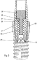
- the insertion cap 3 has above, so the cap opening 11 directed towards interface 17 for connection to the attachment 4, as these are particularly well in Fig. 5 is recognizable.
- the receptacle 13 ' is indicated only schematically.
- the interface 17 can preferably be designed as part of a guide channel, in particular as a screw channel 18. This can extend centered along the longitudinal axis A of the plug cap 3.
- the attachment 4 can be designed as a so-called abutment, that is to say an intermediate element between the artificial dental crown and the implant 2, or can itself be embodied as a tooth crown.
- the attachment 4 is sleeve-shaped at least in sections, wherein the guide channel extends as a screw channel 18 through the insertion cap and as a cylindrical cavity through the attachment 4 and extends along the longitudinal axis A.
- the guide channel extends as a screw channel 18 through the insertion cap and as a cylindrical cavity through the attachment 4 and extends along the longitudinal axis A.
- stop surfaces 25 are arranged for abutment of a screw head 20 of a mechanical connecting means 21, in particular a screw.
- the screw also has a thread 22 which engages in the screw 18 of the interface 17.
- the attachment 4 has an annular end region 26 made up of annular sections and interruptions, which together define a ring.
- the guide channel extends terminally on the outside of the sleeve-shaped receptacle 13 of the male cap 3 and is non-positively applied to this.
- a material reinforcement in the region of the receptacle 13 of the insertion cap 3 so that the opening width d is no longer or only very limited variable.
- the insertion cap 3 Due to the interplay of the attachment 4 and the insertion cap 3, the insertion cap 3 is clamped or latched to the projection 8 of the implant.
- the article 4 serves as a locking element which a fixation by positive locking reached between the plug 3 and the implant.
- the attachment 4 in turn is connected to the insertion cap 3 by the mechanical connection means. By loosening the connecting means, the attachment 4 is detachable from the insertion cap and the insertion cap 3 can be removed from the implant. Thus, the male cap can be replaced.
- the mechanical connection means only connects the attachment 4 with the implant 2 indirectly via the insertion cap.
- the plug cap thus serves as an exchangeable connection means between these two elements of the dental prosthesis and can be replaced for hygienic reasons.
- the male cap may be made of plastic and may contain an antimicrobial agent, e.g. a silver compound.
- the plug-in cap also has an edge 23, which protrudes radially from the cap skirt surface and which delimits the cap opening, wherein this rim rests on the implant and at least partially covers an edge-side end face of the implant.
- the attachment 4 can also have one or more projections 19, recesses and / or depressions, which are provided with corresponding projections, recesses and / or recesses, e.g. the gap-shaped depression 16, in the plug cap 3 form a positive connection for preventing rotation of the attachment 4 relative to the insertion cap 3.
- the insertion cap 3 may preferably be formed of a polyether ketone, in particular of a PEEK, PEKK and / or CF-PEEK.
- the insertion cap comprises an antibacterial and / or anti-inflammatory agent.
- the insertion cap 3 can also have a coupling point, eg a thread, for connection to an insertion aid, through which the insertion sleeve can be introduced into the shell space 6 of the implant 2 or removed from the implant 2.
- a coupling point eg a thread
- the mechanical connection means for connecting the attachment 4 with the insertion cap 3 may be formed as a titanium or gold sheath. Because the connection with the implant 2 takes place via the insertion cap 3, no mechanical damage to the implant due to the mechanical connection means is to be feared.
- a metallic screw can also be used on a plastic screw, for example, CF-PEEK. Terminal the channel 18 is closed with a stopper, not shown.
- the attachment 4 can be made of ceramic materials, zirconia, glass material, metal-ceramic hybrid materials, in particular cermets materials and the like.
- Fig. 6a-6c shows dentures variants 1, 101 and 201 which exemplify different embodiments, which are manufacturable in the context of the present invention.
- the variant of Fig. 6a has been previously described.
- the screw 18 is arranged in a sleeve-shaped male member 29, which can be plugged in a form-fitting manner to the rest of the plug.
- the plug is thus formed in two parts. It is preferred, however, if the male cap is integrally formed in each embodiment variant, wherein instead of the male element, a projection with the corresponding screw 18 is formed monolithically with the remaining male cap.
- the denture variant of Fig. 6b also has an implant 102, a plug cap 103 as a dental insert according to the invention, and an attachment 104.
- the insertion cap 103 has a pin-like projection 121, which extends along the longitudinal axis A from the receptacle 113 into the cap space 124.
- the projection 121 extends into a guide channel 128 which, in this embodiment variant, is formed only in the attachment 104 and wherein the edge is bounded by walls of the attachment 104.
- the projection 121 may have terminal radial projections or recesses 122 for better anchorage of the projection 121 and thus also the entire male cap 103 in a potting compound 123 introduced into the guide channel 128.
- the potting compound 123 may preferably comprise an adhesive or a hardening compound, e.g. a cement or a hardening polymer mass.
- To replace the Einsteckkappe 103 can be done by a drill drilling out of the guide channel 118 and then the top 104 and subsequently also the Einsteckkappe 103 are removed.
- the attachment consists at least in the region of the guide channel 118 of a harder material than the material of the plug and the material of the cured potting compound, so that a boring without damaging the material of the attachment takes place and the reusability of the attachment 104 is made possible.
- the denture variant of Fig. 6c has an implant 202, a plug cap 203 as a dental insert according to the invention, and an attachment 204.
- the Einsteckkappe 203 has a pin-like projection 221, which also as in Fig. 6b protruding along the longitudinal axis of the male from the receptacle 213 in the cap space 224.
- Fig. 6b has the protrusion 221 of the plug cap 204 terminally a latching element 222 which engages with a stop surface 225 of a guide channel 228 of the attachment 204.
- To replace the Einsteckkappe 203 can be done by a drill boring of the guide channel 218 and then the article 204 and subsequently the Einsteckkappe 203 can be removed.
- the locking can also be solved by a tool.
- a predetermined breaking point can be provided in the region of the latching element.
- the attachment consists, at least in the region of the guide channel 218, of a harder material than the material of the insertion cap, in particular the material of the insertion cap in the region of the latching.
Landscapes
- Health & Medical Sciences (AREA)
- Oral & Maxillofacial Surgery (AREA)
- Orthopedic Medicine & Surgery (AREA)
- Dentistry (AREA)
- Epidemiology (AREA)
- Life Sciences & Earth Sciences (AREA)
- Animal Behavior & Ethology (AREA)
- General Health & Medical Sciences (AREA)
- Public Health (AREA)
- Veterinary Medicine (AREA)
- Dental Prosthetics (AREA)
Priority Applications (4)
| Application Number | Priority Date | Filing Date | Title |
|---|---|---|---|
| EP16206721.9A EP3338731A1 (fr) | 2016-12-23 | 2016-12-23 | Insert dentaire destiné à relier un implant dentaire à un support dentaire |
| PCT/EP2017/083939 WO2018115194A1 (fr) | 2016-12-23 | 2017-12-20 | Insert dentaire permettant d'assembler un implant dentaire à une couronne dentaire |
| EP17829635.6A EP3558156B1 (fr) | 2016-12-23 | 2017-12-20 | Insert dentaire destiné à relier un implant dentaire à un support dentaire |
| US16/472,526 US20190314122A1 (en) | 2016-12-23 | 2017-12-20 | Dental insert for connecting a dental implant to a dental abutment |
Applications Claiming Priority (1)
| Application Number | Priority Date | Filing Date | Title |
|---|---|---|---|
| EP16206721.9A EP3338731A1 (fr) | 2016-12-23 | 2016-12-23 | Insert dentaire destiné à relier un implant dentaire à un support dentaire |
Publications (1)
| Publication Number | Publication Date |
|---|---|
| EP3338731A1 true EP3338731A1 (fr) | 2018-06-27 |
Family
ID=57609777
Family Applications (2)
| Application Number | Title | Priority Date | Filing Date |
|---|---|---|---|
| EP16206721.9A Withdrawn EP3338731A1 (fr) | 2016-12-23 | 2016-12-23 | Insert dentaire destiné à relier un implant dentaire à un support dentaire |
| EP17829635.6A Active EP3558156B1 (fr) | 2016-12-23 | 2017-12-20 | Insert dentaire destiné à relier un implant dentaire à un support dentaire |
Family Applications After (1)
| Application Number | Title | Priority Date | Filing Date |
|---|---|---|---|
| EP17829635.6A Active EP3558156B1 (fr) | 2016-12-23 | 2017-12-20 | Insert dentaire destiné à relier un implant dentaire à un support dentaire |
Country Status (3)
| Country | Link |
|---|---|
| US (1) | US20190314122A1 (fr) |
| EP (2) | EP3338731A1 (fr) |
| WO (1) | WO2018115194A1 (fr) |
Citations (4)
| Publication number | Priority date | Publication date | Assignee | Title |
|---|---|---|---|---|
| JP2011120723A (ja) * | 2009-12-10 | 2011-06-23 | Nanto Precision Co Ltd | インプラント |
| EP2382942A1 (fr) * | 2010-04-30 | 2011-11-02 | Nanolize GmbH | Implant dentaire et système d'implant |
| US20160206409A1 (en) * | 2015-01-21 | 2016-07-21 | Kwang Seob Kim | Implant unit |
| US20160354183A1 (en) * | 2015-06-08 | 2016-12-08 | Miguel G. Montero | Screwless dental implant connection |
Family Cites Families (1)
| Publication number | Priority date | Publication date | Assignee | Title |
|---|---|---|---|---|
| US10653506B2 (en) * | 2015-01-05 | 2020-05-19 | Kwang Seob Kim | Implant unit |
-
2016
- 2016-12-23 EP EP16206721.9A patent/EP3338731A1/fr not_active Withdrawn
-
2017
- 2017-12-20 US US16/472,526 patent/US20190314122A1/en not_active Abandoned
- 2017-12-20 EP EP17829635.6A patent/EP3558156B1/fr active Active
- 2017-12-20 WO PCT/EP2017/083939 patent/WO2018115194A1/fr not_active Ceased
Patent Citations (4)
| Publication number | Priority date | Publication date | Assignee | Title |
|---|---|---|---|---|
| JP2011120723A (ja) * | 2009-12-10 | 2011-06-23 | Nanto Precision Co Ltd | インプラント |
| EP2382942A1 (fr) * | 2010-04-30 | 2011-11-02 | Nanolize GmbH | Implant dentaire et système d'implant |
| US20160206409A1 (en) * | 2015-01-21 | 2016-07-21 | Kwang Seob Kim | Implant unit |
| US20160354183A1 (en) * | 2015-06-08 | 2016-12-08 | Miguel G. Montero | Screwless dental implant connection |
Also Published As
| Publication number | Publication date |
|---|---|
| WO2018115194A1 (fr) | 2018-06-28 |
| US20190314122A1 (en) | 2019-10-17 |
| EP3558156B1 (fr) | 2020-10-07 |
| EP3558156A1 (fr) | 2019-10-30 |
Similar Documents
| Publication | Publication Date | Title |
|---|---|---|
| EP1992304A1 (fr) | Implant dentaire, en particulier en matériau céramique | |
| DE102012201092B4 (de) | Zahntechnisches Implantatsystem | |
| CH704382A1 (de) | Zahnersatz-System. | |
| DE102009015358A1 (de) | Schraube, insbesondere Abutmentschraube, Implantat und Gingivaformer für Zahnimplantate | |
| EP2143398A1 (fr) | Implant dentaire avec element intermédiaire élastique | |
| EP3638148B1 (fr) | Système d'implant dentaire comprenant un implant dentaire et un pilier prothétique séparé | |
| DE102005027184B4 (de) | Modellimplantat für Zahnimplantate | |
| EP2368518B1 (fr) | Transfert pour implant dentaire | |
| EP1274365B1 (fr) | Element en forme de tige servant a determiner la position spatiale d'un implant | |
| EP3666224B1 (fr) | Prothèse dentaire pourvue de manchon de raccordement et kit | |
| EP1943979B1 (fr) | Implant dentaire | |
| DE202007018746U1 (de) | Schraubwerkzeug und Halteelement für ein Schraubwerkzeug | |
| DE102014106076A1 (de) | Zahnmedizinisches Implantat | |
| DE19850097C2 (de) | Verfahren und Einrichtung zur Handhabung von implantatgetragenem Zahnersatz | |
| EP1816977A1 (fr) | Implant dentaire | |
| DE3811498A1 (de) | Dentales kieferimplantat | |
| DE102006045187B4 (de) | Verbundsystem für ein zweiteiliges Zahnimplantat | |
| EP3558156B1 (fr) | Insert dentaire destiné à relier un implant dentaire à un support dentaire | |
| DE102005027401A1 (de) | Verfahren zur Sicherung eines medizinischen Elements in einem Implantat und medizinisches Element | |
| DE102008028132A1 (de) | Mehrteiliges Zahnimplantatsystem | |
| DE102006045186B4 (de) | Aufbau für ein zweiteiliges Zahnimplantat, sowie mehrteiliges Zahnimplantatssystem | |
| EP2964133B1 (fr) | Implant dentaire | |
| DE102012110318A1 (de) | Dentalimplantat und dentales Implantatsystem | |
| EP3294190B1 (fr) | Élément à friction | |
| DE102020121126A1 (de) | Verbindungshülse mit Innenkonus für Zahnimplantate |
Legal Events
| Date | Code | Title | Description |
|---|---|---|---|
| PUAI | Public reference made under article 153(3) epc to a published international application that has entered the european phase |
Free format text: ORIGINAL CODE: 0009012 |
|
| AK | Designated contracting states |
Kind code of ref document: A1 Designated state(s): AL AT BE BG CH CY CZ DE DK EE ES FI FR GB GR HR HU IE IS IT LI LT LU LV MC MK MT NL NO PL PT RO RS SE SI SK SM TR |
|
| AX | Request for extension of the european patent |
Extension state: BA ME |
|
| STAA | Information on the status of an ep patent application or granted ep patent |
Free format text: STATUS: THE APPLICATION IS DEEMED TO BE WITHDRAWN |
|
| 18D | Application deemed to be withdrawn |
Effective date: 20190103 |