EP3338744A1 - Solution de compartiment de batterie pour un dispositif de protection auditive - Google Patents
Solution de compartiment de batterie pour un dispositif de protection auditive Download PDFInfo
- Publication number
- EP3338744A1 EP3338744A1 EP16206229.3A EP16206229A EP3338744A1 EP 3338744 A1 EP3338744 A1 EP 3338744A1 EP 16206229 A EP16206229 A EP 16206229A EP 3338744 A1 EP3338744 A1 EP 3338744A1
- Authority
- EP
- European Patent Office
- Prior art keywords
- key
- removable cover
- protection device
- battery compartment
- hearing protection
- Prior art date
- Legal status (The legal status is an assumption and is not a legal conclusion. Google has not performed a legal analysis and makes no representation as to the accuracy of the status listed.)
- Granted
Links
Images





Classifications
-
- H—ELECTRICITY
- H04—ELECTRIC COMMUNICATION TECHNIQUE
- H04R—LOUDSPEAKERS, MICROPHONES, GRAMOPHONE PICK-UPS OR LIKE ACOUSTIC ELECTROMECHANICAL TRANSDUCERS; ELECTRIC HEARING AIDS; PUBLIC ADDRESS SYSTEMS
- H04R1/00—Details of transducers, loudspeakers or microphones
- H04R1/10—Earpieces; Attachments therefor ; Earphones; Monophonic headphones
- H04R1/1083—Reduction of ambient noise
-
- A—HUMAN NECESSITIES
- A61—MEDICAL OR VETERINARY SCIENCE; HYGIENE
- A61F—FILTERS IMPLANTABLE INTO BLOOD VESSELS; PROSTHESES; DEVICES PROVIDING PATENCY TO, OR PREVENTING COLLAPSING OF, TUBULAR STRUCTURES OF THE BODY, e.g. STENTS; ORTHOPAEDIC, NURSING OR CONTRACEPTIVE DEVICES; FOMENTATION; TREATMENT OR PROTECTION OF EYES OR EARS; BANDAGES, DRESSINGS OR ABSORBENT PADS; FIRST-AID KITS
- A61F11/00—Methods or devices for treatment of the ears or hearing sense; Non-electric hearing aids; Methods or devices for enabling ear patients to achieve auditory perception through physiological senses other than hearing sense; Protective devices for the ears, carried on the body or in the hand
- A61F11/06—Protective devices for the ears
- A61F11/14—Protective devices for the ears external, e.g. earcaps or earmuffs
-
- H—ELECTRICITY
- H04—ELECTRIC COMMUNICATION TECHNIQUE
- H04R—LOUDSPEAKERS, MICROPHONES, GRAMOPHONE PICK-UPS OR LIKE ACOUSTIC ELECTROMECHANICAL TRANSDUCERS; ELECTRIC HEARING AIDS; PUBLIC ADDRESS SYSTEMS
- H04R1/00—Details of transducers, loudspeakers or microphones
- H04R1/10—Earpieces; Attachments therefor ; Earphones; Monophonic headphones
- H04R1/1008—Earpieces of the supra-aural or circum-aural type
-
- H—ELECTRICITY
- H04—ELECTRIC COMMUNICATION TECHNIQUE
- H04R—LOUDSPEAKERS, MICROPHONES, GRAMOPHONE PICK-UPS OR LIKE ACOUSTIC ELECTROMECHANICAL TRANSDUCERS; ELECTRIC HEARING AIDS; PUBLIC ADDRESS SYSTEMS
- H04R1/00—Details of transducers, loudspeakers or microphones
- H04R1/10—Earpieces; Attachments therefor ; Earphones; Monophonic headphones
- H04R1/1041—Mechanical or electronic switches, or control elements
-
- H—ELECTRICITY
- H04—ELECTRIC COMMUNICATION TECHNIQUE
- H04R—LOUDSPEAKERS, MICROPHONES, GRAMOPHONE PICK-UPS OR LIKE ACOUSTIC ELECTROMECHANICAL TRANSDUCERS; ELECTRIC HEARING AIDS; PUBLIC ADDRESS SYSTEMS
- H04R1/00—Details of transducers, loudspeakers or microphones
- H04R1/02—Casings; Cabinets ; Supports therefor; Mountings therein
- H04R1/023—Screens for loudspeakers
-
- H—ELECTRICITY
- H04—ELECTRIC COMMUNICATION TECHNIQUE
- H04R—LOUDSPEAKERS, MICROPHONES, GRAMOPHONE PICK-UPS OR LIKE ACOUSTIC ELECTROMECHANICAL TRANSDUCERS; ELECTRIC HEARING AIDS; PUBLIC ADDRESS SYSTEMS
- H04R1/00—Details of transducers, loudspeakers or microphones
- H04R1/10—Earpieces; Attachments therefor ; Earphones; Monophonic headphones
- H04R1/1058—Manufacture or assembly
Definitions
- Embodiments generally relate to hearing protection devices comprising a battery compartment with a removable cover, for example mounted in an ear cup of the hearing protection device.
- hearing protection devices comprising a battery compartment
- battery compartments comprising a key configured to ease the removal process of the removable cover (e.g. to replace batteries).
- hearing protection devices may comprise a battery compartment having a removable cover which requires the user to pull on a U-shaped cantilever snap-fit located on one end of the removable cover and pull out the removable cover once the U-shaped cantilever snap-fit is loose enough.
- the U-shaped cantilever snap-fit on the removable cover is small and may require the use of a tool to ease the difficulty of removing the removable cover via the user's hands.
- the users may have to leave their area of work, remove their personal protective equipment (e.g. hearing protection device, gloves, etc.), detach the removable cover from the battery compartment, replace the batteries, attach the removable cover to the battery compartment, and replace (e.g. don) their personal protective equipment (e.g. hearing protection device, gloves, etc.) before going back to their area of work.
- the user may attempt to remove the removable cover in his/her designated area of work.
- the user may face a safety hazard (e.g. potential hearing damage) from not wearing his/her hearing protection device within a loud working environment (since typically they would have to remove their hearing protection device to replace the batteries).
- a safety hazard e.g. potential hearing damage
- the user may face a safety hazard from having to remove his/her gloves to adequately grasp the U-shaped cantilever snap-fit on the removable cover (since conventional cover removal is extremely difficult while wearing gloves). Also, the user may risk misplacing or losing the removable cover, for example while trying to replace the batteries.
- the Applicants have constructed a battery compartment with an improved removable cover (e.g. comprising a key) to allow the user to more easily and quickly attach and detach the removable cover.
- the device may also comprise a linking element which connects the removable cover to the battery compartment so the user may not potentially lose the removable cover.
- the removable cover with the key may be configured for use with one hand (for example, even when wearing gloves) and may allow the user to replace batteries with greater ease (for example, while still wearing the hearing protection device). This can be especially important for users with hearing protection devices which have high power consumption (e.g. requiring replacement of batteries approximately 1-2 times per week).
- the Applicants have constructed a device which may be used both indoors and outdoors, withstand water from entering into the battery compartment, and prevent air from entering into the ear cup (which might otherwise negatively impact the noise reduction rating (NRR)/hearing protection of the hearing protection device).
- NRR noise reduction rating
- disclosed embodiments may address one or more of such issues with the conventional removable cover located on a battery compartment to increase the ease of removal for the user while also maintaining the sound attenuating properties of the hearing protection device.
- the removable cover typically comprises a key and a main body panel portion.
- the key may typically be configured to allow the user to detach and attach the removable cover to the battery compartment.
- the removable cover may comprise a through-hole and a recessed portion.
- the through-hole may be configured to fit (e.g. correspond with) the key (e.g. to allow the key to slide back and forth through the through-hole and rotate within the through-hole), and the recessed portion (typically located on the exterior of the main body panel portion) may be configured to snugly fit the external portion of the key (e.g.
- the removable cover may comprise a sealing element around the outer circumference to allow the removable cover to seal with the battery compartment.
- the sealing elements may prevent water from entering into the hearing protection device and may have an International Protection (IP) 54 rating designated for devices that prevent water from spraying into the device from any direction.
- IP International Protection
- the battery compartment may comprise a lock-fit aperture configured to correspond with the distal end of the key (to allow the removable cover to lock and unlock from the battery compartment).
- exemplary embodiments typically comprise: a battery compartment (with a lock-fit aperture) and a removable cover which may further comprise a key, a main body panel portion, a through-hole, a recessed portion, and a bias element.
- the key typically may comprise a raised grip, a longitudinal member, and a pin. Additionally, in some embodiments, the key may comprise a circular back plate (e.g. which might correspond to the recessed portion of the main body panel portion of the removable cover). Generally, the raised grip may be located on (e.g. the exterior of, and be a part of) the circular back plate. Typically, the raised grip may project outward away from the removable cover and may intersect the center of the circular back plate (e.g. extend from one end of the circular back plate to the other end of the circular back plate). In some embodiments, the raised grip may comprise a different shape (e.g. other than a line/rectangle) such as an arrow, triangle, diamond, etc.
- a different shape e.g. other than a line/rectangle
- the key may not include a circular back plate.
- the raised grip may fit within the recessed portion of the removable cover and may be operable to rotate without the support of a circular back plate.
- the longitudinal member of the key may be configured to run through the through-hole located in the removable cover and through the center of the battery compartment and into a lock-fit aperture located near the backside of the battery compartment.
- the distal end of the longitudinal member may comprise a pin.
- the pin may be (significantly) shorter than the longitudinal member and may have a smaller diameter than the longitudinal member.
- the pin may be configured to attach perpendicularly to the end of the longitudinal member (e.g. to serve a function similar to that of a key).
- the pin may fit into the lock-fit aperture to lock and unlock the removable cover from the battery compartment.
- the disclosed embodiments may comprise two configurations: an unlocked configuration and a locked configuration.
- the removable cover typically comprises a recessed portion.
- the exterior portion of the key e.g. the grip surface
- the recessed portion corresponds with the (grip surface, e.g. raised grip and/or circular back plate of the) key (e.g. such that the circular back plate and/or raised grip fits within the recessed portion), and wherein the grip surface (e.g. circular back plate of the key) may be configured to fit snugly within the recessed portion (e.g. substantially fill the recessed portion and/or be shaped similarly/correspondingly, so as to allow rotation of the key without any interference by the recessed portion).
- the grip surface e.g. circular back plate of the key
- the grip surface on the key may further comprise a circular back plate (and a raised grip) (configured to provide a larger grip surface area (e.g. larger than merely the raised grip) for the (exterior face of the) key, to facilitate removal of the removable cover from the battery compartment with a gloved hand), wherein the raised grip is mounted on the exterior of the circular back plate (e.g. the circular back plate interfaces with the (central) raised grip), and wherein the circular back plate may be configured to interface/interact with the removable cover (e.g. the circular back plate may be larger than the through-hole in the main body panel portion of the removable cover, and may be configured to allow rotation of the key/circular back plate/raised grip with respect to the main body panel portion of the removable cover).
- a circular back plate and a raised grip
- the raised grip is mounted on the exterior of the circular back plate (e.g. the circular back plate interfaces with the (central) raised grip)
- the circular back plate may be configured to interface/interact with the removable cover (
- the (central) raised grip of the key is often configured to lay flush with the outer surface of the removable cover (e.g. main body panel portion).
- the circular back plate may be configured to lay flush with the outer surface of the removable cover (e.g. main body panel portion), but the raised grip may project outward beyond that outer surface.
- the key pops out automatically and
- a biasing element is configured with respect to the key so that, in the unlocked position, the key automatically pops outward with respect to the main body panel portion of the removable cover).
- the key may be biased outward via a bias element such as a spring.
- the spring may be located at the center of the recessed portion. Additionally, the spring may be configured to wrap around the longitudinal member of the key (since the longitudinal member of the key is configured to run through the through-hole at the center of the removable cover (located in the recessed portion) and then run through the lock-fit aperture located at the backside of the battery compartment). Thus, when the user rotates the key via the raised grip to unlock the battery compartment, the key is configured to automatically project outward away from the main body panel portion of the removable cover. Typically, this results due to the bias element pushing the key outward once the key is in the unlocked configuration. In some embodiments, the bias element may not necessarily be located at the center (and wrapped around the longitudinal member of the key).
- the bias element may be located at multiple points/one or more points behind the circular back plate of the grip surface. Alternatively (or additionally), the bias element may be located within the lock-fit aperture located at the back of the battery compartment (e.g. interacting with the distal end of the key). Persons of skill will appreciate other materials, methods, and/or locations to place the bias element to automatically bias the key outward.
- the key may further comprise a longitudinal member which comprises an interference element.
- a longitudinal member which comprises an interference element.
- two interference elements may be located opposite each other in proximity to the center of the longitudinal member.
- the interference element may be configured to fit within a protruding member (located on the back-side/underside/inner surface of the removable cover/main body panel portion) allowing for longitudinal motion (e.g. inward and outward - forward and backward motion (e.g. linear motion) (e.g. not rotational motion)) of the key (e.g.
- the protruding member acts as (at least a partial) guide rail, allowing longitudinal movement of the pin/distal end of the key (when the interference element interfaces with the protruding member) but preventing rotation of the key (when the interference element interfaces with the protruding member).
- the removable cover may further comprise flexible arms, cavities, and/or protrusions located within the recessed portion.
- the flexible arms may prevent the key from being removed (and/or sliding longitudinally) via the through-hole when the key is in the locked configuration (e.g. the pin lying approximately parallel and/or the interference elements not aligning with the protruding member of the removable cover). This may result due to the fact that the flexible arms may be configured to flex/contract inward but not outward.
- the user may fail at unlocking the removable cover and/or break the parts/elements involved (e.g. removable cover, key, longitudinal member, etc.).
- the removable cover e.g. main body panel portion
- the removable cover may comprise one or more cavities located within the recessed portion.
- the one or more cavities have corresponding protrusions located on the backside of the key (more specifically, typically located on the backside of the circular back plate of the key).
- the one or more protrusions are configured to align (e.g. fit within) with the corresponding number of cavities (to create a firm locked grip) (e.g. to establish a barrier/resistance to overcome when configuring the device to/towards the unlocked configuration) (e.g.
- the device further comprising a resistance mechanism configured to provide a pre-set amount of resistance with respect to (rotation of the key to) moving from locked to unlocked configuration).
- the key may comprise one or more cavities while the main body panel portion (within the recessed portion) of the removable cover may comprise a corresponding number of protrusions.
- the location of the cavities and the protrusions may be switched in some embodiments. Persons of skill will appreciate other forms of adding resistance to the removable cover of the battery compartment to ensure the user does not improperly lock/unlock the removable cover, break the parts involved, and/or to prevent accidental removal of the removable cover from the battery compartment.
- the battery compartment may comprise a lock-fit/corresponding aperture, linking element, and/or welding.
- the lock-fit aperture may be located on the innermost portion (e.g. back-wall) of the battery compartment/recessed body (e.g. behind the batteries) and/or between the battery locations - so that the longitudinal member of the key may extend between the batteries in operation when the cover is locked in place and the batteries are in the battery compartment.
- the linking element such as a rubber string
- the battery compartment may be welded (e.g. via ultrasonic welding) in place within the ear cup (shell) (to prevent/minimize reduction in Noise Reduction Rating (NRR) level of ear cup).
- NRR Noise Reduction Rating
- the welding would result in an airtight mounting of the battery compartment recessed body in the ear cup, and may take place on the interior side of the battery compartment (e.g. the side of the battery compartment comprising the processor).
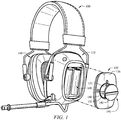
- FIG. 1 illustrates a perspective view of an exemplary embodiment of a hearing protection device 100 comprising one or more ear cups 110.
- at least one ear cup 110 comprises a battery compartment 120, a removable cover 130, and a key.
- the battery compartment 120 may be configured for 2 AA batteries as shown in the embodiment of FIG. 1 .
- the battery compartment 120 may be configured for other variations of batteries (e.g. AAA batteries, C batteries, D batteries, etc.).
- the battery compartment 120 may be located within one ear cup 110 of the hearing protection device 100 (e.g. earmuff), but in some embodiments it may be located on both ear cups 110. As shown in FIG.
- the battery compartment 120 may be fully enclosed/encompassed within and not extending out of the ear cup 110.
- the battery compartment 120 would include a removable cover 130.
- the removable cover 130 in the embodiment of FIG. 1 comprises a key and is shown in the unlocked configuration (e.g. with the key projecting outward away from the removable cover 130) (e.g. with the removable cover 130 detached from the battery compartment 120 of the hearing protection device 100).
- the key comprises a gripping surface 141.
- the gripping surface 141 shown in the embodiment of FIG. 1 comprises a circular back plate 143 and a raised grip 142.
- the circular back plate 143 of the key is operable to fit within (e.g.
- the circular back plate 143 of the key fits snugly within the recessed portion 132, and (in the locked configuration) the circular back plate 143 may lay flush with the main body panel portion 136 (e.g. outer surface) of the removable cover 130.
- the raised grip 142 is configured to allow the user to use his/her fingers (or gloved hands) to grasp the raised grip 142 and rotate the key.
- the raised grip 142 is configured to protrude outwards away from the ear cup 110 so that the user may find the raised grip 142 without difficulty (e.g. by feel).
- the raised grip 142 typically does not protrude outwards too significantly to prevent interference with the user's activities while the hearing protection device 100 is being used (e.g. the raised grip 142 getting tangled with the user's hair, clothes, personal protective equipment (PPE), nearby equipment, etc.). So typically, the raised grip might protrude from 3-5 millimeters. Additionally, the raised grip 142 may be configured to rotate (e.g. by 90 degrees as shown in the embodiment of FIG. 1 ). In the embodiment of FIG. 1 , a 90 degree clockwise rotation may place the key in a locked configuration. The configuration shown in the embodiment of FIG. 1 with the raised grip 142 lying approximately horizontally indicates the key is in an unlocked configuration (see also FIG. 2B ).
- the key may require a greater (e.g. greater than 90 degrees) or lesser (e.g. lesser than 90 degrees) rotation in another direction (e.g. counter-clockwise or clockwise).
- the raised grip 142 may not have to be aligned (approximately) horizontally for the removable cover 130 of the hearing protection device 100 to be in the unlocked configuration.
- the raised grip 142 may not have to be aligned (approximately) vertically for the battery compartment 120 of the hearing protection device 100 to be in the locked configuration (for example, as shown in FIG. 2A ).
- the recessed portion 132 of the removable cover 130 may comprise a cavity 131.
- the one or more cavities 131 may be one or more cavities 131 located within the recessed portion 132 of the main body panel portion 136 of the removable cover 130.
- the one or more cavities 131 have corresponding protrusions located on the backside of the key (more specifically, located on the backside of the circular back plate 143 of the key - see for example FIG. 4B ).
- the one or more protrusions are configured to align (e.g. fit within) with the corresponding number of cavities 131 (to create a firm locked grip) (e.g. to establish a barrier/resistance to overcome when configuring the hearing protection device 100 to/towards the unlocked configuration) (e.g. the hearing protection device further comprising a resistance mechanism configured to provide a pre-set amount of resistance with respect to (rotation of the key to) moving from locked to unlocked configuration).
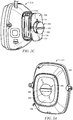
- FIG. 2A illustrates a front view of an exemplary embodiment of an ear cup 210 comprising a removable cover 230 having a main body panel portion 236 and a key in a locked configuration.
- the key shown in the embodiment of FIG. 2A is centrally located on the removable cover 230 with the main body panel portion 236 surrounding the key and comprises a gripping surface 241.
- the gripping surface 241 comprises a circular back plate 243 and a raised grip 242.
- the circular back plate 243 and the raised grip 242 may function similar to the circular back plate 143 and raised grip 142 discussed in reference to the embodiment of FIG. 1 .
- FIG. 1 illustrates a front view of an exemplary embodiment of an ear cup 210 comprising a removable cover 230 having a main body panel portion 236 and a key in a locked configuration.
- the key shown in the embodiment of FIG. 2A is centrally located on the removable cover 230 with the main body panel portion 236 surrounding the key and comprises a gripping surface 241.
- the raised grip 242 is aligned vertically, indicating the removable cover 230 is locked to the battery compartment of the ear cup 210.
- the removable cover 230 e.g. the main body panel portion 236) may be slightly curved inward (e.g. indented) or inset to allow the user to more easily find the removable cover 230 by touch (for example, if the user is wearing the hearing protection device and is not able to see the ear cup 210).
- the raised grip 242 on the grip surface 241 of the key (which projects outward above the outer surface of the main body panel portion 236 of the removable cover 230) may make it easier for the user to find the key to unlock and lock the removable cover 230. In the embodiment of FIG.
- the circular back plate 243 of the grip surface 241 is configured to lay flush with the surrounding main body panel portion 236 (when in locked configuration).
- the circular back plate 243 may protrude outwards or be inset within the recessed portion of the removable cover 230.
- FIG. 2B illustrates a side perspective view of an exemplary embodiment of an ear cup 210 comprising a removable cover 230, a key, and a bias element 233 in an unlocked configuration.
- the key is biased outward away from the removable cover 230 by the bias element 233.
- the bias element 233 is located within the recessed portion 232 of the removable cover 230 (e.g. between the main body panel portion and the circular back plate). More specifically, the bias element 233 shown in the embodiment of FIG. 2B is a spring and is located at the center of the recessed portion 232. Additionally, the spring in the embodiment of FIG.
- the key 2B is configured to wrap around the longitudinal member of the key (since the longitudinal member of the key is configured to run through the through-hole at the center of the removable cover (located in the recessed portion 232) and then run through the lock-fit aperture located at the backside of the battery compartment - when in locked configuration).
- the key when the user rotates the key via the raised grip 242 shown in the embodiment of FIG. 2B and unlocks the battery compartment, the key is configured to automatically project (e.g. pop) outward away from the main body panel portion 236 of the removable cover 230.
- the bias element 233 may not necessarily be located at the center (and wrapped around the longitudinal member of the key).
- the bias element 233 may be located at one or more points behind the circular back plate 243 of the grip surface 241. Also, the bias element 233 may alternatively be located within the lock-fit aperture located at the back of the battery compartment in other embodiments. Additionally, in FIG. 2B , there exist two cavities 231.
- the cavities 231 function similar to the cavities 131 shown in the embodiment of FIG. 1 . Typically, there may be two cavities 231 located opposite of each other (about the key) as shown in the embodiment of FIG. 2B . In some embodiments, the number of cavities 231 may vary depending on what a person of skill deems reasonable.
- FIG. 2C illustrates a side view of an exemplary embodiment of an ear cup 210, similar to the embodiment shown in FIG. 2B , with the key biased outward away from the removable cover 230 and the removable cover 230 detached from the battery compartment 220 (e.g. recessed body).
- the removable cover 230 comprising the key functions/performs in a similar manner as discussed in reference to FIG. 1 above.
- the elements of the removable cover 230 e.g. main body panel portion 236, one or more cavities 231, recessed portion 232, bias element, through-hole, etc.
- the elements of the key e.g.
- the battery compartment 220 comprises 2 AA batteries. In other embodiments, the battery compartment 220 may be configured for other variations of batteries (e.g. AAA batteries, C batteries, D batteries, etc.). Generally in the embodiment of FIG. 2C , the battery compartment 220 comprises a lock-fit aperture (not shown, but located near the backside of the recessed body and between the two batteries allowing the longitudinal member of the key to fit into the lock-fit aperture) (located on the innermost portion (e.g. back-wall) of the battery compartment 220 (e.g.
- the longitudinal member (not shown) of the key comprises a pin located at the end of the key.
- the pin may be configured to run perpendicularly to the longitudinal member.
- FIG. 3A - FIG. 3D illustrate an alternative exemplary embodiment of an ear cup 310 comprising a removable cover 330 and a key similar to the exemplary embodiments shown in the figures discussed above.
- the key differs in configuration (e.g. the key does not comprise a circular back plate, but merely includes a raised grip).
- other elements such as the bias element may vary as well.
- the exemplary embodiments shown in FIG. 3A - FIG. 3D will be discussed in more detail below.
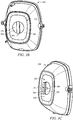
- FIG. 3A illustrates a front view of an exemplary embodiment of an ear cup 310 comprising a removable cover 330 having a main body panel portion 336 and a key in a locked configuration (e.g. the raised grip 342 lying approximately horizontally).
- the key shown in the embodiment of FIG. 3A is centrally located on the main body panel portion 336 of the removable cover 330.
- the gripping surface 341 comprises a raised grip 342 (in the embodiments of FIG. 1 - FIG. 2C , the gripping surface 341 further comprised a circular back plate).
- the raised grip 342 may be configured to extend/project outward away from the hearing protection device (e.g.
- the raised grip 342 may be configured to lie entirely within the recessed portion 332 of the removable cover 330 so as to be flush with the outer surface of the removable cover 330. In other embodiments, the raised grip 342 may be configured to lie entirely within the recessed portion 332 (but perhaps be a bit indented from the outer surface). It is also important to note that the raised grip 342 may not necessarily be configured to lay approximately horizontally to place the removable cover 330 in the locked configuration. In some embodiments, the raised grip 342 may be configured to lay in another orientation (e.g. vertically) to be placed in the locked configuration.
- the orientation of the raised grip 342 may vary as long as it is pre-configured and the user may not change the orientation of the locked configuration and the unlocked configuration during use of the hearing protection device.
- the raised grip 342 is shown to be a bit indented from the outer surface but lies completely within the recessed portion 33 of the removable cover 330 (although in other embodiments, the raised grip may be flush or project slightly outward from the recessed portion).
- the recessed portion 332 of the removable cover 330 may exist to allow the user to easily find the key to detach/attach the removable cover 330 by feeling around the ear cup 310 (rather than having to look for it (e.g. removing the hearing protection device from the user's ears)).
- the shape of the raised grip 342 of the key may vary.
- the shape maybe an arrow, triangle, rhombus, etc.
- the main body panel portion 336 of the removable cover 330 may be slightly curved inward and/or inset allowing the user to more easily find the removable cover 330 by touch (for example, if the user is wearing the hearing protection device and is not able to see the ear cup 310).
- the raised grip 342 on the grip surface 341 of the key may make it easier for the user to find the key to unlock and lock the removable cover 330.
- FIG. 3B illustrates a front view of an exemplary embodiment of an ear cup 310 comprising a removable cover 330 having a main body panel portion 336 and a key in an unlocked configuration (e.g. the raised grip 342 lying approximately vertically).
- the elements of the exemplary embodiment shown in FIG. 3B e.g. ear cup 310 comprising a removable cover 330, a main body panel portion 336, a key, a recessed portion 332, a raised grip 342, a grip surface 341, etc.
- the key has been turned to the unlocked configuration, so that the key may now be used to assist in removing the removable cover 330 (as discussed below with regards to FIG. 3C - FIG. 3D ).
- FIG. 3C illustrates a side perspective view of an exemplary embodiment of an ear cup 310 comprising a removable cover 330 and a key (similar to the exemplary embodiment shown in FIG. 3B ) in an unlocked configuration.
- the key is biased outward away from the removable cover 330 by a bias element.
- the bias element may be located within the recessed portion 332 of the removable cover 330 (e.g. between the raised grip 342 and the main body panel portion 336 of the removable cover 330).
- the bias element may be located at multiple points/one or more points behind the raised grip 342.
- the bias element may be located within the lock-fit aperture located at the back of the battery compartment (e.g.
- the bias element shown in the embodiment of FIG. 3C is a spring and is located within the lock-fit aperture located at the back of the battery compartment.
- the key when the user rotates the key via the raised grip 342 shown in the embodiment of FIG. 3C and unlocks the battery compartment, the key is configured to automatically project outward away from the main body panel portion 336 of the removable cover 330. Typically, this results due to the bias element pushing the key outward once the key is in the unlocked configuration.
- the key may not be biased outward (for example, if the embodiment of FIG. 3C did not include a spring), and the user might instead pull the key outward upon unlocking it (e.g.
- the key is configured to be attached to the main body panel portion 336 in a manner allowing the key to slide longitudinally with respect to the main body panel portion 336 (while remaining (permanently) attached at all times (e.g. because the distal end of the key (and the raised grip 342) is larger than the hole/opening in the main body panel portion 336 through which the longitudinal member 345 of the key passes (e.g. through-hole)))).
- the exemplary embodiment of FIG. 3C does not comprise cavities. In other words, the exemplary embodiment of FIG. 3C does not comprise an additional barrier/resistance to overcome when configuring the device to/towards the unlocked configuration.
- FIG. 3D illustrates a side perspective view of an exemplary embodiment of an ear cup 310, similar to the embodiments shown in FIG. 3A - FIG. 3C , with the key biased outward away from the removable cover 330, in an unlocked configuration, and the removable cover 330 detached from the battery compartment 320.
- the elements of the exemplary embodiment shown in FIG. 3D e.g. ear cup 310 comprising a removable cover 330, a main body panel portion 336, a key, a recessed portion 332, a raised grip 342, a grip surface 341, a battery compartment 320, etc.
- the key comprises a longitudinal member 345 configured to run through the through-hole of the removable cover, through the center of the battery compartment 320 (e.g. between two batteries), and into the corresponding/lock-fit/lock-fit aperture (when in the locked configuration).
- the key comprises a longitudinal member 345 which further comprises a pin 346 (e.g. the pin 346 forms the distal end of the key and may run perpendicular to the longitudinal member 345), and wherein the pin 346 is configured to lock into the lock-fit aperture (so that without further rotation to the unlocked configuration, the key will not move longitudinally).
- the shape of the pin 346 is configured to correspond to the shape of the lock-fit aperture.
- FIG. 4A illustrates a cross-sectional view of an exemplary embodiment of an ear cup 410 (similar to that of FIG. 1 , for example) comprising a removable cover 430, a welded interior cover 460 (e.g. recessed body), a linking element 450, and a key 440 in a locked configuration.
- the key 440 is configured to be attached to the main body panel portion 436 of the removable cover 430 in a manner allowing the key to slide longitudinally with respect to the main body panel portion 436 (while remaining (permanently) attached at all times (e.g.
- the ear cup 410 may also comprise a linking element 450 (located within the battery compartment) which connects the removable cover 430 to the battery compartment so that the user may not potentially lose the removable cover 430 (e.g. to ensure the removable cover 430 remains attached to the hearing protection device even in the unlocked configuration; e.g.
- the battery compartment e.g. recessed body
- the battery compartment may be welded (e.g. via ultrasonic welding) in place within the ear cup (shell) (to prevent/minimize reduction in Noise Reduction Rating (NRR) level of ear cup) (as shown in the exemplary embodiment of FIG. 4A ).
- NRR Noise Reduction Rating
- the hearing protection device may comprise one or more sealing elements 470.
- a first sealing element may be located between the removable cover 430 and the ear cup 410 (e.g. around the circumference/lip/interface).
- a second sealing element may be located between the grip surface of the key 440 and the main body panel portion 436 of the removable cover 430 (e.g. to prevent water and/or air from entering the hearing protection device (e.g. International Protection (IP) rating of IP54; IP54 is a classification designated to devices which prevent water from being sprayed into the device from any direction).
- IP International Protection
- the first seal is located on either the outer edge circumference of the main body panel portion 436 of the removable cover 430 or on the circumference of the opening of the recessed body of the battery compartment (which interfaces with the circumference of the main body panel portion 436 of the removable cover 430).
- the second seal is located on either the outer edge circumference of the grip surface of the key 440 or on the circumference of the recessed portion of the main body panel portion 436 of the removable cover 430 (which interfaces with the circumference of the grip surface of the key 440).
- the ear cup comprises 410 both the first seal and the second seal.
- FIG. 4B illustrates a perspective view of an exemplary embodiment of a key 440 (similar to that of FIG. 1 , 2A , 2B , and 4 ) comprising a grip surface 441 (further comprising a raised grip 442 and a circular back plate 443), two protrusions 444, a longitudinal member 445, a pin 446, and two interference elements 447.
- the grip surface 441 comprises a (central) raised grip 442 which extends/projects outward away from the hearing protection device (e.g.
- a circular back plate 443 (configured to provide a larger grip surface 441 area (e.g. larger than merely the raised grip 442) for the (exterior face of the) key 440, to facilitate removal of the removable cover from the battery compartment with a gloved hand).
- the raised grip 442 is mounted on the exterior of the circular back plate 443 (e.g. the circular back plate 443 interfaces with the (central) raised grip 442), and wherein the circular back plate 443 is configured to interface/interact with the removable cover (e.g.
- the circular back plate 443 is larger than the opening in the main body panel portion of the removable cover, and is configured to allow rotation of the key 440/circular back plate 443/raised grip 442 with respect to the main body panel portion of the removable cover).
- the key 440 may comprise one or more protrusions 444 located on the backside/underside of the circular back plate 443 of the key 440, wherein the corresponding number of cavities are located within the recessed portion of the main body panel portion of the removable cover, and wherein, in the locked configuration, the one or more protrusions 444 are configured to align (e.g. fit within) with the corresponding number of cavities (to create a firm locked grip) (e.g.
- the key 440 may comprise one or more cavities while the main body panel portion (within the recessed portion) of the removable cover may comprise a corresponding number of protrusions 444. In other words, the location of the cavities and the protrusions may be switched in some embodiments. Also shown in the embodiment of FIG. 4B , the key 440 may comprise a longitudinal member 445 configured to function/perform similarly to the longitudinal member 445 shown in previous exemplary embodiments of FIG.
- the longitudinal member 445 may further comprise a pin 446 (e.g. at the distal end of the key) and two interference elements 447.
- the interference elements 447 may be configured to fit within a protruding member (located on the back-side/underside/inner surface of the removable cover) allowing for longitudinal motion (e.g. inward and outward - forward and backward motion (e.g. linear motion) (e.g. not rotational motion)) of the key 440 (e.g.
- the protruding member acts as (at least a partial) guide rail, allowing longitudinal movement of the pin 446 (when the interference element 447 interfaces with the protruding member) but preventing rotation of the key 440 (when the interference element 447 interfaces with the protruding member).
- the pin 446 may form the distal end of the key 440 and be configured to fit within the (lock-fit/corresponding/lock-fit) aperture of the battery compartment to lock and unlock the removable cover from the battery compartment.
- FIG. 4C illustrates a front view of an exemplary embodiment of an ear cup 410 comprising a battery compartment 420 (e.g. recessed body - for example similar to FIG. 1 , 2C , 3D, and 4A ) which further comprises a lock-fit aperture 421.
- the battery compartment 420 is configured to fit 2 AA batteries.
- the battery compartment 420 may be configured to fit a varying number of different types of batteries such as AA, AAA, C, or D batteries.
- the lock-fit aperture 421 is located on the innermost portion (e.g. back-wall) of the battery compartment 420 (e.g. in recessed body behind the batteries) and/or between the battery locations - so that the longitudinal member of the key may extend between the batteries in operation when the cover is locked in place and the batteries are in the battery compartment 420.
- FIG. 4D illustrates an interior view of an exemplary embodiment of an ear cup 410 (e.g. the back side of the embodiment shown in FIG. 4C ) comprising a welded interior cover 460 of the recessed body of the battery compartment with regards to the ear cup.
- the welded interior cover 460 functions similarly to the welded interior cover 460 shown in the exemplary embodiment of FIG. 4A .
- the welded interior cover 460 is configured to prevent communication of air between the battery compartment and the inside of the ear cup 410 (and to maintain sound attenuation of the hearing protection device) (to prevent/minimize reduction in Noise Reduction Rating (NRR) level of ear cup).
- NRR Noise Reduction Rating
- FIG. 5A - FIG. 8 illustrate an exemplary embodiment of a removable cover for an ear cup. These figures illustrate the varying key configurations which exist while the device is being configured from an unlocked configuration to a locked configuration or vice versa. Thus, the exemplary embodiments shown in FIG. 5A - FIG. 8 will walk through how the key operates and will be discussed in more detail below.
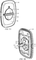
- FIG. 5A illustrates a front view of an exemplary embodiment of a removable cover 530 comprising a key in the unlocked configuration (e.g. the raised grip 542 of the key lying horizontally).
- FIG. 5A illustrates an ear cup 530 similar to the one shown in the exemplary embodiment of FIG. 2A .
- the raised grip 542 lies vertically in the locked configuration.
- the elements shown in the embodiment of FIG. 2A are similar to the elements shown in the embodiment of FIG. 5A .
- the key is shown to be centrally located on the removable cover 530 with the main body panel portion 536 surrounding the key and comprises a gripping surface 541.
- FIG. 5A illustrates a front view of an exemplary embodiment of a removable cover 530 comprising a key in the unlocked configuration (e.g. the raised grip 542 of the key lying horizontally).
- FIG. 5A illustrates an ear cup 530 similar to the one shown in the exemplary embodiment of FIG. 2A .
- the raised grip 542 lies vertically
- the gripping surface 541 comprises a circular back plate 543 and a raised grip 542.
- the circular back plate 543 and the raised grip 542 may function similar to the circular back plate 543 and raised grip 542 discussed in reference to the embodiment of FIG. 1 .
- FIG. 5B illustrates a back/interior view of an exemplary embodiment of a removable cover 530 comprising a key 540 in the unlocked configuration, similar to the embodiment shown in FIG. 5A .
- the interference elements 547 located on the longitudinal member 545 are shown to align with the protruding member (e.g. guide rail) located on the back-side/underside/inner surface of the removable cover 530. This may allow the longitudinal member 545 of the key 540 to move inward and outward (e.g. forward and backward motion, linear motion, not rotational motion).
- the key 540 may not be rotated (until the user depresses the key 540 back into the battery compartment).
- the pin 546 may be pulled out of the lock-fit aperture located at the back of the battery compartment (as shown in the embodiment of FIG. 4C ).
- the removable cover 530 may comprise flexible arms 535 as shown in the exemplary embodiment of FIG. 5B . The flexible arms 535 may prevent the key 540 from being removed via the through-hole 537 when the key 540 is in the locked configuration (e.g. the pin 546 lying approximately parallel and/or the interference elements 547 not aligning with the protruding member 534 of the removable cover 530).
- the flexible arms 535 may be configured to flex/contract inward but not outward.
- the user may fail at unlocking the removable cover 530 and/or break the parts/elements involved (e.g. removable cover 530, key 540, longitudinal member 545, etc.).
- FIG. 6A illustrates a front view of an exemplary embodiment of a removable cover 630 comprising a key in the unlocked configuration and biased outward away from the removable cover 630.
- the exemplary embodiment shown in FIG. 6A is similar to the exemplary embodiment shown in FIG. 5A wherein the key is shown to be centrally located on the recessed portion 632 of the removable cover 630 with the main body panel portion 636 surrounding the key and the key comprising a gripping surface 641.
- the gripping surface 641 comprises a circular back plate 643 and a raised grip 642.
- the circular back plate 643 and the raised grip 642 may function similar to the circular back plate 143 and raised grip 142 discussed in reference to the embodiment of FIG. 1 .
- FIG. 6B illustrates a back/interior view of an exemplary embodiment of a removable cover 630 comprising a key 640 in the unlocked configuration and biased outward away from the removable cover 630, similar to the embodiment shown in FIG. 6A (showing the opposite/interior side of the removable cover 630 rather than the exterior side).
- the elements e.g. through-hole 637, pins 646, longitudinal member 645, etc.
- the interference elements are not visible as they are in the protruding member 634 (e.g. guide rail) of the removable cover 630.
- the interference elements are configured to fit within the protruding member 634 to prevent rotation but allow inward and outward (e.g. linear) motion.
- the longitudinal member 645 may be able to move outward because the interference elements are not configured to interact with the flexible arms 635 in the unlocked configuration. If the key 640 was in the locked configuration, the user may not be able to move the key 640 outward (due to the fact that the interference elements would interact with the flexible arms 635 which would prevent further outward motion (the flexible arms 635 may be configured to allow inward motion but not outward motion)).
- FIG. 7A illustrates a front view of an exemplary embodiment of a removable cover 730 comprising a key in a partially locked configuration (e.g. neither entirely locked nor unlocked- e.g. mid turn as a user moves from the unlocked to the locked configuration or vice versa).
- the key is fully compressed/retract within the recessed portion of the main body panel portion of the removable cover, allowing turning of the raised grip.
- the raised grip 742 of the grip surface 741 is configured to lay approximately half-way between the locked configuration and the unlocked configuration.
- the elements in the exemplary embodiment of FIG. 7A e.g.
- grip surface 741, raised grip 742, circular back plate 743, main body panel portion 736, etc. are similar to the elements shown in the exemplary embodiment of FIG. 5A and FIG. 6A .
- the elements in the exemplary embodiment of FIG. 7A function similarly to those in FIG. 5A and FIG. 6A .
- FIG. 7B illustrates a back/interior view of an exemplary embodiment of a removable cover 730 comprising a key in the partially locked configuration (e.g. neither locked nor unlocked), similar to the embodiment shown in FIG. 7A (showing the opposite/interior side of the removable cover 730 rather than the exterior side).
- the elements e.g. interference elements 747, key 740, pin 746, longitudinal member 745, protruding member 734, flexible arms 735, through-hole 737, etc.
- the elements e.g. interference elements 747, key 740, pin 746, longitudinal member 745, protruding member 734, flexible arms 735, through-hole 737, etc.
- FIG. 7B illustrates a back/interior view of an exemplary embodiment of a removable cover 730 comprising a key in the partially locked configuration (e.g. neither locked nor unlocked), similar to the embodiment shown in FIG. 7A (showing the opposite/interior side of the removable cover 730 rather than the exterior
- the interference elements 747 are oriented diagonally (so that the interference elements 747 are not configured to fit within the protruding member 734 (e.g. guide rail) of the removable cover 730 or interact with the flexible arms 735 of the removable cover 730).
- the key 740 may not be operable to move outward (from the through-hole 737) (e.g. away) from the removable cover 730 unless the user rotates the key 740 further so that the interference elements 747 align with the protruding member 734 and/or do not interact with the flexible arms 735.
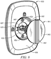
- FIG. 8 illustrates an exploded perspective view of an exemplary embodiment of a removable cover 830 comprising a recessed portion 832, flexible arms 835, two cavities 831, and a key biased outward, via a bias element 833, away from the removable cover 830.
- the key is oriented in the locked configuration (e.g. the raised grip 842 oriented approximately vertically).
- the key comprises a bias element 833 which is a spring in the embodiment of FIG. 8 .
- the spring is configured to wrap around the longitudinal member.
- the recessed portion 832 of the removable cover 830 comprises two cavities 831.
- the cavities 831 are configured to interact with the corresponding number of protrusions located on the backside of the grip surface 841 (e.g. circular back plate 843) of the key (e.g. to establish a barrier/resistance to overcome when configuring the device to/towards the unlocked configuration) (e.g. the device further comprising a resistance mechanism configured to provide a pre-set amount of resistance with respect to (rotation of the key to) moving from locked to unlocked configuration).
- the key is configured to fit through the through-hole 837 of the removable cover 830.
- the interference elements 847 may interact with the flexible arms 835 to push the flexible arms 835 inward to create room for the key to enter via the through-hole 837.
- the flexible arms 835 provide an extra resistance to overcome (in addition to the cavities 831 and the bias element 833) when attempting to lock the removable cover 830 using the key.
- the key is in the locked configuration, it is configured to fit snugly within the recessed portion 832 of the removable cover 830 (the circular back plate 843 of the key lying flush with the main body panel portion 836 of the removable cover 830).
- the raised grip 842 may extend outward in comparison to the main body panel portion 836 to allow the user to more easily find/grasp the key.
- Exemplary embodiments might also relate to methods for using a hearing protection device comprising a removable cover operable to be unlocked and locked using a key (e.g. similar to those described above, which may be considered optionally incorporated herein with respect to the discussion of the methods).
- Such method embodiments might include, but are not limited to, the following:
Landscapes
- Engineering & Computer Science (AREA)
- Health & Medical Sciences (AREA)
- Acoustics & Sound (AREA)
- Physics & Mathematics (AREA)
- Life Sciences & Earth Sciences (AREA)
- Signal Processing (AREA)
- Biomedical Technology (AREA)
- Psychology (AREA)
- Otolaryngology (AREA)
- Heart & Thoracic Surgery (AREA)
- Vascular Medicine (AREA)
- Animal Behavior & Ethology (AREA)
- General Health & Medical Sciences (AREA)
- Public Health (AREA)
- Veterinary Medicine (AREA)
- Biophysics (AREA)
- Battery Mounting, Suspending (AREA)
- Manufacturing & Machinery (AREA)
Priority Applications (3)
| Application Number | Priority Date | Filing Date | Title |
|---|---|---|---|
| EP16206229.3A EP3338744B1 (fr) | 2016-12-22 | 2016-12-22 | Solution de compartiment de batterie pour un dispositif de protection auditive |
| US15/840,057 US10349162B2 (en) | 2016-12-22 | 2017-12-13 | Battery compartment solution for a hearing protection device |
| CN201711392095.6A CN108210167B (zh) | 2016-12-22 | 2017-12-21 | 用于听力保护设备的电池盒解决方案 |
Applications Claiming Priority (1)
| Application Number | Priority Date | Filing Date | Title |
|---|---|---|---|
| EP16206229.3A EP3338744B1 (fr) | 2016-12-22 | 2016-12-22 | Solution de compartiment de batterie pour un dispositif de protection auditive |
Publications (2)
| Publication Number | Publication Date |
|---|---|
| EP3338744A1 true EP3338744A1 (fr) | 2018-06-27 |
| EP3338744B1 EP3338744B1 (fr) | 2022-04-27 |
Family
ID=57714434
Family Applications (1)
| Application Number | Title | Priority Date | Filing Date |
|---|---|---|---|
| EP16206229.3A Active EP3338744B1 (fr) | 2016-12-22 | 2016-12-22 | Solution de compartiment de batterie pour un dispositif de protection auditive |
Country Status (3)
| Country | Link |
|---|---|
| US (1) | US10349162B2 (fr) |
| EP (1) | EP3338744B1 (fr) |
| CN (1) | CN108210167B (fr) |
Families Citing this family (6)
| Publication number | Priority date | Publication date | Assignee | Title |
|---|---|---|---|---|
| USD857649S1 (en) * | 2017-06-22 | 2019-08-27 | Honeywell International Inc. | Battery compartment locking mechanism |
| USD856594S1 (en) * | 2017-10-27 | 2019-08-13 | Honeywell International Inc. | Pair of ear muffs |
| CN110972011A (zh) * | 2019-11-29 | 2020-04-07 | 歌尔股份有限公司 | 蓝牙耳机 |
| USD943548S1 (en) * | 2020-05-06 | 2022-02-15 | Razer (Asia-Pacific) Pte. Ltd. | Headphone |
| AU2022253837B2 (en) * | 2021-04-09 | 2025-06-12 | Tecmen Electronics Co., Ltd | Ear muff and ear muff assembly |
| IT202200000035A1 (it) * | 2022-01-03 | 2023-07-03 | St Microelectronics Srl | Corpo solido di un dispositivo biomedico per l'acquisizione di parametri fisiologici di un paziente, e relativo dispositivo biomedico |
Citations (3)
| Publication number | Priority date | Publication date | Assignee | Title |
|---|---|---|---|---|
| WO1999012385A1 (fr) * | 1997-08-15 | 1999-03-11 | Peltor Ab | Dispositif de protection anti-bruit |
| US20150117660A1 (en) * | 2013-10-28 | 2015-04-30 | 3M Innovative Properties Company | Adaptive frequency response, adaptive automatic level control and handling radio communications for a hearing protector |
| WO2016126476A1 (fr) * | 2015-02-02 | 2016-08-11 | 3M Innovative Properties Company | Protecteur antibruit avec compartiment pour bloc de batteries rechargeables |
Family Cites Families (13)
| Publication number | Priority date | Publication date | Assignee | Title |
|---|---|---|---|---|
| JPH0645957A (ja) * | 1992-04-15 | 1994-02-18 | Nec Corp | 腕時計型個別呼出用受信機の裏カバー構造 |
| US6218044B1 (en) * | 1998-01-26 | 2001-04-17 | Asahi Kogaku Kogyo Kabushiki Kaisha | Opening and closing mechanism for battery compartment and water-proof/drip proof cover for the same |
| GB2390394B (en) * | 2002-07-03 | 2004-05-26 | Shyang Feng Electric & Machine | Improved electronic lock |
| US7097746B1 (en) * | 2002-11-20 | 2006-08-29 | Advanced Bionics Corporation | Anodic protection of electrical contacts |
| NZ549912A (en) * | 2006-09-14 | 2009-07-31 | Phitek Systems Ltd | Battery Door |
| CN101997097B (zh) * | 2009-08-21 | 2014-03-26 | 深圳富泰宏精密工业有限公司 | 电池盖卡锁装置 |
| TW201107614A (en) * | 2009-08-28 | 2011-03-01 | Fih Hong Kong Ltd | Battery cover latch structure |
| JP5432694B2 (ja) * | 2009-12-11 | 2014-03-05 | 株式会社オーディオテクニカ | ノイズキャンセルヘッドホンの電池収納機構 |
| CN202091300U (zh) * | 2010-12-30 | 2011-12-28 | 北京奇耐特长城座椅有限公司 | 可移动座椅的快速安装紧固件 |
| CN102815190B (zh) * | 2012-08-10 | 2015-02-11 | 王俊 | 电池锁止机构 |
| CN203081920U (zh) * | 2012-12-21 | 2013-07-24 | 中国电子科技集团公司第十五研究所 | 一种用于手持机电池仓盖的旋转锁扣 |
| US9717633B2 (en) * | 2013-03-15 | 2017-08-01 | Michael Waters | Lighted headgear |
| CN105140435B (zh) * | 2015-08-07 | 2017-12-22 | 深圳市大疆灵眸科技有限公司 | 电池舱及具有该电池舱的云台 |
-
2016
- 2016-12-22 EP EP16206229.3A patent/EP3338744B1/fr active Active
-
2017
- 2017-12-13 US US15/840,057 patent/US10349162B2/en active Active
- 2017-12-21 CN CN201711392095.6A patent/CN108210167B/zh active Active
Patent Citations (3)
| Publication number | Priority date | Publication date | Assignee | Title |
|---|---|---|---|---|
| WO1999012385A1 (fr) * | 1997-08-15 | 1999-03-11 | Peltor Ab | Dispositif de protection anti-bruit |
| US20150117660A1 (en) * | 2013-10-28 | 2015-04-30 | 3M Innovative Properties Company | Adaptive frequency response, adaptive automatic level control and handling radio communications for a hearing protector |
| WO2016126476A1 (fr) * | 2015-02-02 | 2016-08-11 | 3M Innovative Properties Company | Protecteur antibruit avec compartiment pour bloc de batteries rechargeables |
Also Published As
| Publication number | Publication date |
|---|---|
| CN108210167B (zh) | 2021-12-28 |
| US10349162B2 (en) | 2019-07-09 |
| CN108210167A (zh) | 2018-06-29 |
| US20180184194A1 (en) | 2018-06-28 |
| EP3338744B1 (fr) | 2022-04-27 |
Similar Documents
| Publication | Publication Date | Title |
|---|---|---|
| US10349162B2 (en) | Battery compartment solution for a hearing protection device | |
| JP2012048885A (ja) | バッテリ装置 | |
| WO2008014172A3 (fr) | Dispositif de protection auditive double | |
| CA2696859A1 (fr) | Verrou de pile | |
| CN214967652U (zh) | 防护耳罩及其组件 | |
| PH12018502677A1 (en) | Dental cleaning tool with handle shield | |
| US9112585B2 (en) | Disposable protection enclosure for portable electronic devices | |
| US20140079262A1 (en) | Hearing device comprising a locking mechanism for an external connector and method thereof | |
| PH12018502557A1 (en) | Dental cleaning tool with integrated shield | |
| TW201944970A (zh) | 帶輔助清潔工具之牙科清潔工具及用於輔助清潔工具之整合護罩 | |
| US20140224283A1 (en) | Protecting and purging hearing aid devices | |
| US20240074493A1 (en) | Aerosol Generating System Comprising a Case and an Inhalation Device and Method of Removing the Inhalation Device from the Case | |
| JP2011124133A (ja) | コンセント | |
| CN112972116A (zh) | 防护耳罩及其组件 | |
| US20190028798A1 (en) | Earphone protection device | |
| US12382231B2 (en) | Sealing sleeve for protection of components in a hearing device | |
| IT202100004358A1 (it) | Casco con braccetto portamicrofono | |
| TW202002874A (zh) | 清潔設備 | |
| CN212752940U (zh) | 一种美容设备的保护盖结构 | |
| TWM575324U (zh) | 具一體成型之外罩之牙齒清潔工具 | |
| KR102122989B1 (ko) | 탈부착 가능한 배터리가 구비된 무선 청소기 | |
| JP2019024629A (ja) | 着脱可能な替刃ケースを備える工具 | |
| BR102013001990A2 (pt) | Ferramenta elétrica do tipo injeção de água | |
| TW201914546A (zh) | 具有一體成型防護件之牙齒清潔工具 | |
| JP2015017676A (ja) | ガスソケット |
Legal Events
| Date | Code | Title | Description |
|---|---|---|---|
| PUAI | Public reference made under article 153(3) epc to a published international application that has entered the european phase |
Free format text: ORIGINAL CODE: 0009012 |
|
| STAA | Information on the status of an ep patent application or granted ep patent |
Free format text: STATUS: REQUEST FOR EXAMINATION WAS MADE |
|
| 17P | Request for examination filed |
Effective date: 20161222 |
|
| AK | Designated contracting states |
Kind code of ref document: A1 Designated state(s): AL AT BE BG CH CY CZ DE DK EE ES FI FR GB GR HR HU IE IS IT LI LT LU LV MC MK MT NL NO PL PT RO RS SE SI SK SM TR |
|
| AX | Request for extension of the european patent |
Extension state: BA ME |
|
| GRAP | Despatch of communication of intention to grant a patent |
Free format text: ORIGINAL CODE: EPIDOSNIGR1 |
|
| STAA | Information on the status of an ep patent application or granted ep patent |
Free format text: STATUS: GRANT OF PATENT IS INTENDED |
|
| INTG | Intention to grant announced |
Effective date: 20210602 |
|
| RAP3 | Party data changed (applicant data changed or rights of an application transferred) |
Owner name: HONEYWELL INTERNATIONAL INC. |
|
| RIN1 | Information on inventor provided before grant (corrected) |
Inventor name: OHLANDER, LISA Inventor name: WILSON, MAY Inventor name: XU, ALEX |
|
| GRAJ | Information related to disapproval of communication of intention to grant by the applicant or resumption of examination proceedings by the epo deleted |
Free format text: ORIGINAL CODE: EPIDOSDIGR1 |
|
| STAA | Information on the status of an ep patent application or granted ep patent |
Free format text: STATUS: REQUEST FOR EXAMINATION WAS MADE |
|
| INTC | Intention to grant announced (deleted) | ||
| GRAP | Despatch of communication of intention to grant a patent |
Free format text: ORIGINAL CODE: EPIDOSNIGR1 |
|
| STAA | Information on the status of an ep patent application or granted ep patent |
Free format text: STATUS: GRANT OF PATENT IS INTENDED |
|
| INTG | Intention to grant announced |
Effective date: 20211118 |
|
| GRAS | Grant fee paid |
Free format text: ORIGINAL CODE: EPIDOSNIGR3 |
|
| GRAA | (expected) grant |
Free format text: ORIGINAL CODE: 0009210 |
|
| STAA | Information on the status of an ep patent application or granted ep patent |
Free format text: STATUS: THE PATENT HAS BEEN GRANTED |
|
| AK | Designated contracting states |
Kind code of ref document: B1 Designated state(s): AL AT BE BG CH CY CZ DE DK EE ES FI FR GB GR HR HU IE IS IT LI LT LU LV MC MK MT NL NO PL PT RO RS SE SI SK SM TR |
|
| REG | Reference to a national code |
Ref country code: GB Ref legal event code: FG4D |
|
| REG | Reference to a national code |
Ref country code: CH Ref legal event code: EP |
|
| REG | Reference to a national code |
Ref country code: DE Ref legal event code: R096 Ref document number: 602016071459 Country of ref document: DE |
|
| REG | Reference to a national code |
Ref country code: AT Ref legal event code: REF Ref document number: 1486369 Country of ref document: AT Kind code of ref document: T Effective date: 20220515 |
|
| REG | Reference to a national code |
Ref country code: IE Ref legal event code: FG4D |
|
| REG | Reference to a national code |
Ref country code: LT Ref legal event code: MG9D |
|
| REG | Reference to a national code |
Ref country code: NL Ref legal event code: MP Effective date: 20220427 |
|
| REG | Reference to a national code |
Ref country code: AT Ref legal event code: MK05 Ref document number: 1486369 Country of ref document: AT Kind code of ref document: T Effective date: 20220427 |
|
| PG25 | Lapsed in a contracting state [announced via postgrant information from national office to epo] |
Ref country code: NL Free format text: LAPSE BECAUSE OF FAILURE TO SUBMIT A TRANSLATION OF THE DESCRIPTION OR TO PAY THE FEE WITHIN THE PRESCRIBED TIME-LIMIT Effective date: 20220427 |
|
| PG25 | Lapsed in a contracting state [announced via postgrant information from national office to epo] |
Ref country code: SE Free format text: LAPSE BECAUSE OF FAILURE TO SUBMIT A TRANSLATION OF THE DESCRIPTION OR TO PAY THE FEE WITHIN THE PRESCRIBED TIME-LIMIT Effective date: 20220427 Ref country code: PT Free format text: LAPSE BECAUSE OF FAILURE TO SUBMIT A TRANSLATION OF THE DESCRIPTION OR TO PAY THE FEE WITHIN THE PRESCRIBED TIME-LIMIT Effective date: 20220829 Ref country code: NO Free format text: LAPSE BECAUSE OF FAILURE TO SUBMIT A TRANSLATION OF THE DESCRIPTION OR TO PAY THE FEE WITHIN THE PRESCRIBED TIME-LIMIT Effective date: 20220727 Ref country code: LT Free format text: LAPSE BECAUSE OF FAILURE TO SUBMIT A TRANSLATION OF THE DESCRIPTION OR TO PAY THE FEE WITHIN THE PRESCRIBED TIME-LIMIT Effective date: 20220427 Ref country code: HR Free format text: LAPSE BECAUSE OF FAILURE TO SUBMIT A TRANSLATION OF THE DESCRIPTION OR TO PAY THE FEE WITHIN THE PRESCRIBED TIME-LIMIT Effective date: 20220427 Ref country code: GR Free format text: LAPSE BECAUSE OF FAILURE TO SUBMIT A TRANSLATION OF THE DESCRIPTION OR TO PAY THE FEE WITHIN THE PRESCRIBED TIME-LIMIT Effective date: 20220728 Ref country code: FI Free format text: LAPSE BECAUSE OF FAILURE TO SUBMIT A TRANSLATION OF THE DESCRIPTION OR TO PAY THE FEE WITHIN THE PRESCRIBED TIME-LIMIT Effective date: 20220427 Ref country code: ES Free format text: LAPSE BECAUSE OF FAILURE TO SUBMIT A TRANSLATION OF THE DESCRIPTION OR TO PAY THE FEE WITHIN THE PRESCRIBED TIME-LIMIT Effective date: 20220427 Ref country code: BG Free format text: LAPSE BECAUSE OF FAILURE TO SUBMIT A TRANSLATION OF THE DESCRIPTION OR TO PAY THE FEE WITHIN THE PRESCRIBED TIME-LIMIT Effective date: 20220727 Ref country code: AT Free format text: LAPSE BECAUSE OF FAILURE TO SUBMIT A TRANSLATION OF THE DESCRIPTION OR TO PAY THE FEE WITHIN THE PRESCRIBED TIME-LIMIT Effective date: 20220427 |
|
| PG25 | Lapsed in a contracting state [announced via postgrant information from national office to epo] |
Ref country code: RS Free format text: LAPSE BECAUSE OF FAILURE TO SUBMIT A TRANSLATION OF THE DESCRIPTION OR TO PAY THE FEE WITHIN THE PRESCRIBED TIME-LIMIT Effective date: 20220427 Ref country code: PL Free format text: LAPSE BECAUSE OF FAILURE TO SUBMIT A TRANSLATION OF THE DESCRIPTION OR TO PAY THE FEE WITHIN THE PRESCRIBED TIME-LIMIT Effective date: 20220427 Ref country code: LV Free format text: LAPSE BECAUSE OF FAILURE TO SUBMIT A TRANSLATION OF THE DESCRIPTION OR TO PAY THE FEE WITHIN THE PRESCRIBED TIME-LIMIT Effective date: 20220427 Ref country code: IS Free format text: LAPSE BECAUSE OF FAILURE TO SUBMIT A TRANSLATION OF THE DESCRIPTION OR TO PAY THE FEE WITHIN THE PRESCRIBED TIME-LIMIT Effective date: 20220827 |
|
| REG | Reference to a national code |
Ref country code: DE Ref legal event code: R097 Ref document number: 602016071459 Country of ref document: DE |
|
| PG25 | Lapsed in a contracting state [announced via postgrant information from national office to epo] |
Ref country code: SM Free format text: LAPSE BECAUSE OF FAILURE TO SUBMIT A TRANSLATION OF THE DESCRIPTION OR TO PAY THE FEE WITHIN THE PRESCRIBED TIME-LIMIT Effective date: 20220427 Ref country code: SK Free format text: LAPSE BECAUSE OF FAILURE TO SUBMIT A TRANSLATION OF THE DESCRIPTION OR TO PAY THE FEE WITHIN THE PRESCRIBED TIME-LIMIT Effective date: 20220427 Ref country code: RO Free format text: LAPSE BECAUSE OF FAILURE TO SUBMIT A TRANSLATION OF THE DESCRIPTION OR TO PAY THE FEE WITHIN THE PRESCRIBED TIME-LIMIT Effective date: 20220427 Ref country code: EE Free format text: LAPSE BECAUSE OF FAILURE TO SUBMIT A TRANSLATION OF THE DESCRIPTION OR TO PAY THE FEE WITHIN THE PRESCRIBED TIME-LIMIT Effective date: 20220427 Ref country code: DK Free format text: LAPSE BECAUSE OF FAILURE TO SUBMIT A TRANSLATION OF THE DESCRIPTION OR TO PAY THE FEE WITHIN THE PRESCRIBED TIME-LIMIT Effective date: 20220427 Ref country code: CZ Free format text: LAPSE BECAUSE OF FAILURE TO SUBMIT A TRANSLATION OF THE DESCRIPTION OR TO PAY THE FEE WITHIN THE PRESCRIBED TIME-LIMIT Effective date: 20220427 |
|
| PLBE | No opposition filed within time limit |
Free format text: ORIGINAL CODE: 0009261 |
|
| STAA | Information on the status of an ep patent application or granted ep patent |
Free format text: STATUS: NO OPPOSITION FILED WITHIN TIME LIMIT |
|
| PG25 | Lapsed in a contracting state [announced via postgrant information from national office to epo] |
Ref country code: AL Free format text: LAPSE BECAUSE OF FAILURE TO SUBMIT A TRANSLATION OF THE DESCRIPTION OR TO PAY THE FEE WITHIN THE PRESCRIBED TIME-LIMIT Effective date: 20220427 |
|
| 26N | No opposition filed |
Effective date: 20230130 |
|
| PG25 | Lapsed in a contracting state [announced via postgrant information from national office to epo] |
Ref country code: SI Free format text: LAPSE BECAUSE OF FAILURE TO SUBMIT A TRANSLATION OF THE DESCRIPTION OR TO PAY THE FEE WITHIN THE PRESCRIBED TIME-LIMIT Effective date: 20220427 |
|
| REG | Reference to a national code |
Ref country code: CH Ref legal event code: PL |
|
| REG | Reference to a national code |
Ref country code: BE Ref legal event code: MM Effective date: 20221231 |
|
| PG25 | Lapsed in a contracting state [announced via postgrant information from national office to epo] |
Ref country code: LU Free format text: LAPSE BECAUSE OF NON-PAYMENT OF DUE FEES Effective date: 20221222 |
|
| PG25 | Lapsed in a contracting state [announced via postgrant information from national office to epo] |
Ref country code: LI Free format text: LAPSE BECAUSE OF NON-PAYMENT OF DUE FEES Effective date: 20221231 Ref country code: IE Free format text: LAPSE BECAUSE OF NON-PAYMENT OF DUE FEES Effective date: 20221222 Ref country code: CH Free format text: LAPSE BECAUSE OF NON-PAYMENT OF DUE FEES Effective date: 20221231 |
|
| PG25 | Lapsed in a contracting state [announced via postgrant information from national office to epo] |
Ref country code: BE Free format text: LAPSE BECAUSE OF NON-PAYMENT OF DUE FEES Effective date: 20221231 |
|
| PG25 | Lapsed in a contracting state [announced via postgrant information from national office to epo] |
Ref country code: IT Free format text: LAPSE BECAUSE OF FAILURE TO SUBMIT A TRANSLATION OF THE DESCRIPTION OR TO PAY THE FEE WITHIN THE PRESCRIBED TIME-LIMIT Effective date: 20220427 |
|
| PG25 | Lapsed in a contracting state [announced via postgrant information from national office to epo] |
Ref country code: HU Free format text: LAPSE BECAUSE OF FAILURE TO SUBMIT A TRANSLATION OF THE DESCRIPTION OR TO PAY THE FEE WITHIN THE PRESCRIBED TIME-LIMIT; INVALID AB INITIO Effective date: 20161222 |
|
| PG25 | Lapsed in a contracting state [announced via postgrant information from national office to epo] |
Ref country code: CY Free format text: LAPSE BECAUSE OF FAILURE TO SUBMIT A TRANSLATION OF THE DESCRIPTION OR TO PAY THE FEE WITHIN THE PRESCRIBED TIME-LIMIT Effective date: 20220427 |
|
| PG25 | Lapsed in a contracting state [announced via postgrant information from national office to epo] |
Ref country code: MK Free format text: LAPSE BECAUSE OF FAILURE TO SUBMIT A TRANSLATION OF THE DESCRIPTION OR TO PAY THE FEE WITHIN THE PRESCRIBED TIME-LIMIT Effective date: 20220427 |
|
| PG25 | Lapsed in a contracting state [announced via postgrant information from national office to epo] |
Ref country code: MC Free format text: LAPSE BECAUSE OF FAILURE TO SUBMIT A TRANSLATION OF THE DESCRIPTION OR TO PAY THE FEE WITHIN THE PRESCRIBED TIME-LIMIT Effective date: 20220427 |
|
| PG25 | Lapsed in a contracting state [announced via postgrant information from national office to epo] |
Ref country code: TR Free format text: LAPSE BECAUSE OF FAILURE TO SUBMIT A TRANSLATION OF THE DESCRIPTION OR TO PAY THE FEE WITHIN THE PRESCRIBED TIME-LIMIT Effective date: 20220427 Ref country code: MC Free format text: LAPSE BECAUSE OF FAILURE TO SUBMIT A TRANSLATION OF THE DESCRIPTION OR TO PAY THE FEE WITHIN THE PRESCRIBED TIME-LIMIT Effective date: 20220427 |
|
| PG25 | Lapsed in a contracting state [announced via postgrant information from national office to epo] |
Ref country code: MT Free format text: LAPSE BECAUSE OF FAILURE TO SUBMIT A TRANSLATION OF THE DESCRIPTION OR TO PAY THE FEE WITHIN THE PRESCRIBED TIME-LIMIT Effective date: 20220427 |
|
| PG25 | Lapsed in a contracting state [announced via postgrant information from national office to epo] |
Ref country code: BG Free format text: LAPSE BECAUSE OF FAILURE TO SUBMIT A TRANSLATION OF THE DESCRIPTION OR TO PAY THE FEE WITHIN THE PRESCRIBED TIME-LIMIT Effective date: 20220427 |
|
| PG25 | Lapsed in a contracting state [announced via postgrant information from national office to epo] |
Ref country code: BG Free format text: LAPSE BECAUSE OF FAILURE TO SUBMIT A TRANSLATION OF THE DESCRIPTION OR TO PAY THE FEE WITHIN THE PRESCRIBED TIME-LIMIT Effective date: 20220427 |
|
| REG | Reference to a national code |
Ref country code: DE Ref legal event code: R081 Ref document number: 602016071459 Country of ref document: DE Owner name: HONEYWELL SAFETY PRODUCTS USA, INC., WILMINGTO, US Free format text: FORMER OWNER: HONEYWELL INTERNATIONAL INC., MORRIS PLAINS, NJ, US |
|
| REG | Reference to a national code |
Ref country code: GB Ref legal event code: 732E Free format text: REGISTERED BETWEEN 20250515 AND 20250521 |
|
| PGFP | Annual fee paid to national office [announced via postgrant information from national office to epo] |
Ref country code: GB Payment date: 20251223 Year of fee payment: 10 |
|
| PGFP | Annual fee paid to national office [announced via postgrant information from national office to epo] |
Ref country code: FR Payment date: 20251223 Year of fee payment: 10 |
|
| PGFP | Annual fee paid to national office [announced via postgrant information from national office to epo] |
Ref country code: DE Payment date: 20251229 Year of fee payment: 10 |