EP3338949B1 - Outil et procédé de laminage profond - Google Patents
Outil et procédé de laminage profond Download PDFInfo
- Publication number
- EP3338949B1 EP3338949B1 EP17204596.5A EP17204596A EP3338949B1 EP 3338949 B1 EP3338949 B1 EP 3338949B1 EP 17204596 A EP17204596 A EP 17204596A EP 3338949 B1 EP3338949 B1 EP 3338949B1
- Authority
- EP
- European Patent Office
- Prior art keywords
- axis
- shaft
- assembly
- hub
- tool
- Prior art date
- Legal status (The legal status is an assumption and is not a legal conclusion. Google has not performed a legal analysis and makes no representation as to the accuracy of the status listed.)
- Active
Links
Images


Classifications
-
- B—PERFORMING OPERATIONS; TRANSPORTING
- B24—GRINDING; POLISHING
- B24B—MACHINES, DEVICES, OR PROCESSES FOR GRINDING OR POLISHING; DRESSING OR CONDITIONING OF ABRADING SURFACES; FEEDING OF GRINDING, POLISHING, OR LAPPING AGENTS
- B24B39/00—Burnishing machines or devices, i.e. requiring pressure members for compacting the surface zone; Accessories therefor
- B24B39/04—Burnishing machines or devices, i.e. requiring pressure members for compacting the surface zone; Accessories therefor designed for working external surfaces of revolution
-
- B—PERFORMING OPERATIONS; TRANSPORTING
- B23—MACHINE TOOLS; METAL-WORKING NOT OTHERWISE PROVIDED FOR
- B23P—METAL-WORKING NOT OTHERWISE PROVIDED FOR; COMBINED OPERATIONS; UNIVERSAL MACHINE TOOLS
- B23P9/00—Treating or finishing surfaces mechanically, with or without calibrating, primarily to resist wear or impact, e.g. smoothing or roughening turbine blades or bearings; Features of such surfaces not otherwise provided for, their treatment being unspecified
- B23P9/02—Treating or finishing by applying pressure, e.g. knurling
-
- B—PERFORMING OPERATIONS; TRANSPORTING
- B23—MACHINE TOOLS; METAL-WORKING NOT OTHERWISE PROVIDED FOR
- B23Q—DETAILS, COMPONENTS, OR ACCESSORIES FOR MACHINE TOOLS, e.g. ARRANGEMENTS FOR COPYING OR CONTROLLING; MACHINE TOOLS IN GENERAL CHARACTERISED BY THE CONSTRUCTION OF PARTICULAR DETAILS OR COMPONENTS; COMBINATIONS OR ASSOCIATIONS OF METAL-WORKING MACHINES, NOT DIRECTED TO A PARTICULAR RESULT
- B23Q1/00—Members which are comprised in the general build-up of a form of machine, particularly relatively large fixed members
-
- B—PERFORMING OPERATIONS; TRANSPORTING
- B24—GRINDING; POLISHING
- B24B—MACHINES, DEVICES, OR PROCESSES FOR GRINDING OR POLISHING; DRESSING OR CONDITIONING OF ABRADING SURFACES; FEEDING OF GRINDING, POLISHING, OR LAPPING AGENTS
- B24B27/00—Other grinding machines or devices
- B24B27/0038—Other grinding machines or devices with the grinding tool mounted at the end of a set of bars
-
- B—PERFORMING OPERATIONS; TRANSPORTING
- B24—GRINDING; POLISHING
- B24B—MACHINES, DEVICES, OR PROCESSES FOR GRINDING OR POLISHING; DRESSING OR CONDITIONING OF ABRADING SURFACES; FEEDING OF GRINDING, POLISHING, OR LAPPING AGENTS
- B24B39/00—Burnishing machines or devices, i.e. requiring pressure members for compacting the surface zone; Accessories therefor
-
- B—PERFORMING OPERATIONS; TRANSPORTING
- B25—HAND TOOLS; PORTABLE POWER-DRIVEN TOOLS; MANIPULATORS
- B25J—MANIPULATORS; CHAMBERS PROVIDED WITH MANIPULATION DEVICES
- B25J15/00—Gripping heads and other end effectors
- B25J15/0019—End effectors other than grippers
-
- B—PERFORMING OPERATIONS; TRANSPORTING
- B21—MECHANICAL METAL-WORKING WITHOUT ESSENTIALLY REMOVING MATERIAL; PUNCHING METAL
- B21D—WORKING OR PROCESSING OF SHEET METAL OR METAL TUBES, RODS OR PROFILES WITHOUT ESSENTIALLY REMOVING MATERIAL; PUNCHING METAL
- B21D39/00—Application of procedures in order to connect objects or parts, e.g. coating with sheet metal otherwise than by plating; Tube expanders
- B21D39/02—Application of procedures in order to connect objects or parts, e.g. coating with sheet metal otherwise than by plating; Tube expanders of sheet metal by folding, e.g. connecting edges of a sheet to form a cylinder
- B21D39/021—Application of procedures in order to connect objects or parts, e.g. coating with sheet metal otherwise than by plating; Tube expanders of sheet metal by folding, e.g. connecting edges of a sheet to form a cylinder for panels, e.g. vehicle doors
- B21D39/023—Application of procedures in order to connect objects or parts, e.g. coating with sheet metal otherwise than by plating; Tube expanders of sheet metal by folding, e.g. connecting edges of a sheet to form a cylinder for panels, e.g. vehicle doors using rollers
-
- Y—GENERAL TAGGING OF NEW TECHNOLOGICAL DEVELOPMENTS; GENERAL TAGGING OF CROSS-SECTIONAL TECHNOLOGIES SPANNING OVER SEVERAL SECTIONS OF THE IPC; TECHNICAL SUBJECTS COVERED BY FORMER USPC CROSS-REFERENCE ART COLLECTIONS [XRACs] AND DIGESTS
- Y10—TECHNICAL SUBJECTS COVERED BY FORMER USPC
- Y10S—TECHNICAL SUBJECTS COVERED BY FORMER USPC CROSS-REFERENCE ART COLLECTIONS [XRACs] AND DIGESTS
- Y10S901/00—Robots
- Y10S901/30—End effector
- Y10S901/41—Tool
Definitions
- the disclosed subject matter relates generally to materials processing, and more specifically to apparatus and methods for deep rolling metals to induce compressive stresses.
- a low plasticity burnishing (LPB) process can be used on aluminum fan blade roots to improve damage tolerance from e.g., corrosion. This can increase fatigue life or maintain fatigue life in the presence of damage (e.g., corrosion pits).
- LPB low plasticity burnishing
- LPB tools for complex geometries utilize a ball bearing at the end of an axisymmetric, hydraulically actuated shaft.
- this tool is expensive and it involves complex processing steps.
- the small surface area of a ball bearing unnecessarily slows production time and throughput.
- These known tools also cannot be readily used with widely available machine tools due to the need to maintain and constantly adjust hydraulic pressure on the bearing surface.
- An alternative process includes deep rolling process, which can induce high compressive stresses up to 1.5 mm depth from the surface of a material through localized plastic deformation to prevent corrosion pits, foreign object damage, crack initiation, etc.
- US2014/0130321 discloses a method for providing a surface treatment along the surface of a work piece, using a burnishing tool having a tool head comprising a bearing for supporting a rolling element and an encasement for supporting the bearing.
- WO2015/125084 discloses a roller hemming head comprising an upper head portion and a lower head portion carrying one or more hemming rollers.
- Controlling the contact stress between the roller and material being processed is important to achieving desired improvements in material properties. With insufficient contact stress, little or no improvement will be achieved. In addition, there is also a need to customize the applied load and consequently the contact stress along the deep rolling path. Too high of a contact stress can damage the material on/near the surface resulting in a decrement in properties.
- An embodiment of a non-axisymmetric tool assembly which is given by claim 1, includes a spring-loaded shaft assembly disposed along a first axis, a hub, and a roller disk.
- the hub is connected to a distal end of the spring-loaded shaft assembly.
- the hub has an upper hub portion adjacent to the distal end of the spring-loaded shaft assembly aligned with the first axis, and a lower hub portion extending along a second axis.
- the second axis forms a nonzero angle relative to the first axis.
- the roller disk is joined to the lower portion of the hub, and has a working surface about its perimeter.
- the roller disk is rotatable about the second axis parallel to the second portion of the hub.
- the roller disk has a working surface about its perimeter including a profile along its width such that an effective radius of the roller disk varies along a width thereof.
- An embodiment of a method which is given by claim 9, includes supporting a workpiece in a fixture, the workpiece having at least one nonplanar surface.
- a first rolling operation is performed on the nonplanar surface using a non axisymmetric tool assembly.
- the first rolling operation includes applying a downward force to a proximal end of a spring-loaded deep rolling tool shaft aligned with a first axis. The downward force is applied along the first axis such that the downward force is transferred through the shaft to a hub disposed at a distal end of the shaft assembly.
- the transferred downward force is transmitted from an upper portion of the hub aligned with the first axis to a lower portion of the hub parallel to a second axis, the second axis forming a nonzero angle relative to the first axis, about which a roller disk is supported by one or more bearings.
- a resulting compressive force is applied to the first nonplanar surface of the workpiece via a working surface of the roller disk.
- the working surface includes a profile along its width such than an effective radius of the roller disk varies along a width thereof, such that the resulting compressive force applied to the first nonplanar surface varies along the width of the working surface.
- a roller disk with a crowned or otherwise nonplanar working surface about its perimeter can be attached to an end of a spring loaded shaft.
- the tool can be attached to a device to process one or more parts.
- the tool uses multiple tool passes to induce residual compressive stresses while maintaining the appropriate level or range of contact stresses at the roller's point of contact via selective spring loading of the tool.
- FIG. 1 shows workpiece 10, which can be supported in a suitable fixture (not shown).
- Workpiece 10 has airfoil 12 and dovetail root 14.
- At least one nonplanar surface is to be processed (e.g., junction 16 between airfoil 12 and root 14) to have residual compressive stresses near the surface in and around junction 16.
- workpiece 10 is an aluminum alloy fan blade for a turbofan engine, but the process can be adapted to nearly any workpiece having a nonplanar surface into which residual compression stresses are desired to be incorporated.
- FIG. 2 shows roller disk 20 processing junction 16 of workpiece / blade 10 between airfoil 12 and root 14.
- Disk 20 can be joined to a portion of hub 22 with roller disk 20 rotatable about an axis 24 angled relative to a downward force direction F.
- axis 24 is normal to downward force direction F and thus, resulting downward contact force is applied to junction 16 generally in direction F as well.
- Disk 20 has working surface 26 about its perimeter 28, and can include a profile along its width 30 (best seen in FIGS. 3 and 4 ), such that an effective radius of the roller disk varies along a width thereof. It can be seen in FIG. 2 that the disk should be of a radius that provides clearance over protruding regions of the workpiece (e.g., dovetail root 14). In a conventional arrangement for processing a modern aluminum fan blade dovetail, this requires a minimum disk radius of about 2 inches (51 cm), but the size will vary depending on a particular application.
- Hub 22 connects disk 20 to a shaft through which the downward force can be applied in direction F.
- Tool assembly 31 includes spring-loaded shaft assembly 32 disposed along axis 34, which is parallel to downward force direction F.
- Hub 22 can have a first / upper portion 36A along axis 34 and a second / lower portion 36B at a nonzero angle relative to axis 34. This angle is therefore consistent with the nonzero angle between axis 24 and direction F.
- Operation of tool assembly 31 can be as follows.
- the rolling operation can include applying a force in direction F along axis 34 such that the applied force is transferred through spring-loaded shaft assembly 32, hub 22, and roller disk 20 to a first nonplanar surface of the workpiece (e.g., junction 16).
- the resulting force applied to the first nonplanar surface varies along the width of working surface 26 of the disk due to the variable profile across width 30 (seen in FIG. 2 ).
- At least one rolling operation can be performed on a nonplanar surface using a tool like that shown in FIG. 3.
- FIG. 3 depicts roller disk 20 joined to second / lower portion 36B of hub 22, and which is rotatable about axis 24 through second / lower portion 36B of hub 22.
- Roller disk 20 can be supported on one or more bearings (best seen in the exploded view of FIG. 4 ).
- disk 20 can have working surface 26 about perimeter 28, and can include a variable or crowned profile.
- an effective radius (and thus applied bearing stresses) of roller disk 20 varies along working surface 26.
- working surface 26 can additionally have one or more peaks, troughs, etc. The resulting profile can thus either be curved, slanted, or flat.
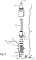
- Spring-loaded shaft assembly 32 can take several different forms.
- resilient element 46 is disposed at distal end 48 of shaft assembly 32, while a rigid shaft 50 (best seen in FIG. 4 ) can be supported on a device to restrain its movement only along first axis 14. This can include one or more linear bearings 49.
- shaft assembly 32 can include a flexible beam without a separate resilient element.
- resilient element 46 certain non-limiting embodiments include a plurality of stacked Belleville washers 52 which can be selected in number and properties in order to provide a desired level of resilience.
- resilient element 30 can include a diaphragm spring or the like.
- tool assembly 31 can also optionally include other elements.
- tool assembly 31 can include tool holder 56 mounted to proximal end 58 of rigid shaft 50 and/or shaft assembly 32.
- Tool holder 56 can be a standard or custom adapter or other device to facilitate attachment of tool assembly 31 to commercially available multi-axis computerized numerical control (CNC) machines (not shown).
- CNC computerized numerical control
- Tool holder 56 can additionally or alternatively facilitate attachment to other devices capable of steering tool assembly 31 while simultaneously applying sufficient (but not excessive) force in downward direction F to induce the desired compressive stresses.
- tool assembly 31 can include load cell 60 to measure the force at the contact surface (see FIG. 4 ).
- Load cell 60 can optionally be disposed along axis 34 adjacent to resilient element 46, and can include a wired and/or wireless connection 62 for controller 64. This will be explained in more detail below.
- FIG. 4 shows an exploded view of tool assembly 31 from FIG. 3 .
- tool assembly 31 can include the following details.
- shaft assembly 32 is restricted to movement only along first axis 14.
- shaft assembly 32 can include linear bearing 48 arranged along axis 34 for supporting rigid shaft 50. This simplifies determination of the downward force that needs to be applied in direction F, as any deflection away from that axis causes a reduction in the actual downward force vectors, while also applying unwanted transverse forces on the tool working surface.
- hub 22 includes first and second portions 50A, 50B which form a right, or other, angle therebetween.
- Roller disk 20 is supported on a bearing or other device so that it is rotatable about axis 24.
- axis 24 is perpendicular to first axis 14.
- working surface 26 of roller disk 20 is symmetrically crowned from a center to opposing first and second edges.
- working surface varies according to a desired load profile along the tool path and can include peaks, troughs, curves, etc.
- Shaft assembly 32 can be calibrated before or between uses to provide a desired force concentration at working surface 26 of roller disk 20.
- at least one of rigid shaft 50 and resilient element 36 can be calibrated so that the force applied to the tool in direction F (shown in FIGS. 2 and 3 ) and transmitted through roller disk 20 is sufficient to impart a residual compression stress in the workpiece at the first nonplanar surface (e.g. junction 16 in FIGS. 1 and 2 ).
- the deep rolling tool described heretofore can be used in a number of different applications, depending on the required accuracy and precision of the applied forces needed. Success in some cases can be achieved by merely controlling the tool load within previously determined upper and lower bounds, such as through spring loading the tool and applying a target amount of compression to the spring.
- the compliance obtained by using a spring loaded tool enables an acceptable level of load control during processing but there is no record of what the actual contact stress was over the surface. However, this is the cheapest and often simplest option, where any suitable mechanical device with an ability to provide a controlled downward force can be used.
- a load cell or another feedback mechanism can be incorporated into the tool that allows monitoring and/or real-time adjustment of the force applied through the roller to the workpiece.
- the tool can process a part using multiple tool passes while maintaining the appropriate level of contact stress at the roller's point of contact.
- the feedback is logged for quality control, so that it can be determined whether any irregularities occurred in the process. This is useful where scrapping and reprocessing parts is not a significant cost or limiting factor.
- load cell 60 can optionally be incorporated into tool assembly 32.
- Load cell 60 in certain embodiments, is contiguous to resilient element 46 (e.g., plurality of Belleville washers 52), and enables real time monitoring of the applied load during processing.
- resilient element 46 e.g., plurality of Belleville washers 52
- a deep rolling tool with an integral load cell thus enables verification of a key process parameter, roller load, which is critical for quality control in many production environments.
- Process consistency could be further enhanced by using the load cell for closed loop load control which improve the precision with which the load could be maintained.
- Such a system would be much more tolerant of dimensional variability in the components being processed. It will also ensure that there are no microcracks on surface due to inadvertent localized application of intensive pressure.
- Load cell 60 can be in wired or wireless communication with a controller 64 and/or monitor adapted to receive wired or wireless signals corresponding to an instantaneous load on resilient element 36.
- Controller / monitor 64 can include closed-loop feedback logic, by which it can be adapted to vary a force applied in direction F (see also FIGS. 2 and 3 ) on tool assembly 31, along axis 34.
- Operating load cell 60 can generate signals corresponding to an instantaneous load on resilient element 46.
- the magnitude of the force can be based at least in part on one or more of the signals received from and generated by load cell 60.
- the applied force is varied based on a plurality of signals from load cell 60 to impart a substantially equal residual compression stress in the workpiece along a tool rolling path on the first nonplanar surface.
- tool assembly 31 can require that the CNC machine be provided with more complex programming even for some relatively simple tool paths. Depending on the desired tool paths and number of passes, programming and use of a CNC machine may be unnecessary or prohibitively complex, in which case, tool assembly 31 can be mounted to a different machine to apply the desired force over the contact path. While certain processes can generally performed using a specialized tool in a conventional CNC milling machine, the deep rolling tool can be inconsistent with generic subroutines and tool paths used to manipulate conventional axisymmetric tools.
- the deep rolling tool which is not axisymmetric, has additional path programming constraints. While planar surfaces can be processed by the deep rolling tool using a 3-axis CNC machine, more complex geometry components will require at least a 5-axis machine and in some instances a 6-axis machine may be necessary. Maintaining the normality and orientation constraints for deep rolling of complex component geometries can be challenging as the tool path programming software won't automatically satisfy these required constraints. While creative programming can generally overcome these issues it may require an experienced and highly skilled programmer.
- Robotic assembly 100 can include, for example, a plurality of linear arms 102 connected in series between base end 104 and working end 106. Adjacent ones of arms 102 can be connected via a corresponding plurality of multi-axis joints 110 such that working end 106 is articulated by movement of one or more of arms 102 relative to one or more of multi-axis joints 110.
- Operation of a robotic assembly such as assembly 100 in FIG. 5 can include using it to apply a downward force over a rolling path of non-axisymmetric deep rolling tool assembly 31.
- the downward force is applied to a proximal end of a spring-loaded tool shaft (best seen in FIG. 2 ) aligned with a first axis, such that the downward force is transferred through the shaft to a hub disposed at a distal end of the shaft assembly (also best seen in FIG. 2 ).
- robotic assembly 100 is sufficiently programmed and/or controlled to provide the appropriate instantaneous feedback of downward force, and the resilient element in tool 31 can be modified or omitted as needed.
- the transferred downward force is transmitted from an upper portion of the hub aligned with the first axis to a lower portion of the hub parallel to a second axis.
- the second axis forms a nonzero angle relative to the first axis, about which a roller disk is supported by one or more bearings.
- a resulting compressive force is applied to the first nonplanar surface of the workpiece via a working surface of the roller disk.
- a typical commercial robot arm has more degrees of freedom than a 5-axis milling machine which facilitates processing of complex geometry parts.
- Current commercially available robot arms have been developed to the point where they can withstand the combination of high loads and precision required in deep rolling applications.
- the software for controlling robot arms is different to that for CNC milling machines and is more suited to maintaining the required orientation constraints of a multi-axis deep rolling tool. Also, it is easier to accommodate processing of large components using a robot arm, as the part does not have to fit inside the machine as it does with a milling machine.
- An embodiment of a tool assembly includes spring-loaded shaft assembly disposed along a first axis; a hub connected to a distal end of the spring-loaded shaft assembly, the hub having an upper hub portion adjacent to the distal end of the spring-loaded shaft assembly aligned with the first axis, and a lower hub portion extending along a second axis, the second axis forming a nonzero angle relative to the first axis; and a roller disk joined to the lower portion of the hub, the roller disk having a working surface about its perimeter and being rotatable about the second axis parallel to the second portion of the hub.
- the working surface including a profile along its width such that an effective radius of the roller disk varies along a width thereof.
- the assembly of the preceding paragraph can optionally include, additionally and/or alternatively, any one or more of the following features, configurations and/or additional components: A further embodiment of the foregoing assembly, wherein the shaft assembly comprises a flexible shaft.
- the shaft assembly comprises: a rigid shaft; and a resilient element disposed at a distal end of the shaft assembly proximate to the hub.
- An embodiment of a method includes supporting a workpiece in a fixture, the workpiece having a first nonplanar surface: and performing a first rolling operation on the first nonplanar surface using a non-axisymmetric tool assembly, the first rolling operation comprising: applying a downward force to a proximal end of a spring-loaded deep rolling tool shaft aligned with a first axis, the downward force applied along the first axis such that the downward force is transferred through the shaft to a hub disposed at a distal end of the shaft assembly; and transmitting the transferred downward force from an upper portion of the hub aligned with the first axis to a lower portion of the hub parallel to a second axis, the second axis forming a nonzero angle relative to the first axis, about which a roller disk is supported by one or more bearings, such that a resulting compressive force is applied to the first nonplanar surface of the workpiece via a working surface of the roller disk.
- the method of the preceding paragraph can optionally include, additionally and/or alternatively, any one or more of the following features, configurations, steps, and/or additional components: A further embodiment of any of the foregoing methods, wherein the working surface of the roller disk is crowned from a center to opposing first and second edges.
- the deep rolling tool shaft comprises: a rigid shaft extending along the first axis; and a resilient element disposed at a distal end of the rigid shaft adjacent to the hub.
- a further embodiment of any of the foregoing methods and further comprising using the tool to perform a second rolling operation on a second nonplanar surface of the workpiece.
- roller disk is rotatable about the second axis perpendicular to the first axis.
Landscapes
- Engineering & Computer Science (AREA)
- Mechanical Engineering (AREA)
- Robotics (AREA)
- Rolling Contact Bearings (AREA)
Claims (14)
- Ensemble outil non axisymétrique (31) comprenant :un ensemble arbre à ressort (32) disposé le long d'un premier axe (34) ;un moyeu (22) relié à une extrémité distale de l'ensemble arbre à ressort (32), le moyeu (22) ayant une partie de moyeu supérieure (36A) adjacente à l'extrémité distale de l'ensemble arbre à ressort (32) alignée avec le premier axe (34), et une partie de moyeu inférieure (36B) s'étendant le long d'un second axe (24), le second axe (24) formant un angle non nul par rapport au premier axe (34) ;un disque à rouleaux (20) relié à la partie inférieure (36B) du moyeu, le disque à rouleaux (20) ayant une surface de travail (26) autour de son périmètre et pouvant tourner autour du second axe (24) parallèle à la seconde partie (36B) du moyeu, la surface de travail (26) comportant un profil le long de sa largeur (30) de sorte qu'un rayon effectif du disque à rouleaux (20) varie le long de sa largeur.
- Ensemble (31) selon la revendication 1, dans lequel l'ensemble arbre (32) comprend un arbre flexible.
- Ensemble (31) selon la revendication 1, dans lequel l'ensemble arbre (32) comprend :un arbre rigide (50) ; etun élément élastique (46) disposé au niveau d'une extrémité distale (48) de l'ensemble arbre (32) à proximité du moyeu.
- Ensemble (31) selon la revendication 3, dans lequel l'arbre rigide (50) est supporté par un palier linéaire (49) disposé le long du premier axe (34).
- Ensemble (31) selon la revendication 3 ou 4, dans lequel l'élément élastique (46) comprend une pluralité de rondelles Belleville empilées (52), ou
dans lequel l'élément élastique comprend un ressort à diaphragme. - Ensemble (31) selon une quelconque revendication précédente, et comprenant en outre un porte-outil (56) monté sur une extrémité proximale (58) de l'arbre.
- Ensemble (31) selon une quelconque revendication précédente, dans lequel la partie de moyeu supérieure (36A) et la partie de moyeu inférieure (36B) définissent un angle droit,
dans lequel, éventuellement, le disque à rouleaux (20) peut tourner autour du second axe (24) perpendiculaire au premier axe. - Ensemble (31) selon une quelconque revendication précédente, dans lequel la surface de travail (26) du disque à rouleaux (20) est bombée depuis un centre jusqu'à des premier et second bords opposés.
- Procédé comprenant :le support d'une pièce à usiner (10) dans un élément de fixation, la pièce à usiner (10) ayant une première surface non plane ; etla mise en œuvre d'une première opération de laminage sur la première surface non plane en utilisant un ensemble outil non axisymétrique (31), la première opération de laminage comprenant :la transmission de la force descendante transférée depuis une partie supérieure du moyeu (36A) alignée avec le premier axe (34) jusqu'à une partie inférieure du moyeu (36B) parallèle à un second axe (24), le second axe (24) formant un angle non nul par rapport au premier axe (34), autour duquel un disque à rouleaux (20) est supporté par un ou plusieurs paliers, de sorte qu'une force de compression résultante est appliquée sur la première surface non plane de la pièce à usiner (10) par l'intermédiaire d'une surface de travail (26) du disque à rouleaux ; dans lequel la surface de travail (26) comporte un profil le long de sa largeur (30) de sorte qu'un rayon effectif du disque à rouleaux (20) varie le long de sa largeur, de sorte que la force de compression résultante appliquée sur la première surface non plane varie le long de la largeur (30) de la surface de travail.
l'application d'une force descendante à une extrémité proximale d'un arbre d'outil de laminage profond à ressort (32) alignée avec un premier axe (34), la force descendante étant appliquée le long du premier axe (34) de sorte que la force descendante est transférée à travers l'arbre (32) à un moyeu disposé au niveau d'une extrémité distale de l'ensemble arbre ; - Procédé selon la revendication 9, dans lequel la surface de travail (26) du disque à rouleaux (20) est bombée depuis un centre jusqu'à des premier et second bords opposés.
- Procédé selon la revendication 9 ou 10, dans lequel l'arbre d'outil de laminage profond (32) comprend un arbre flexible, ou
dans lequel l'arbre d'outil de laminage profond (32) comprend :un arbre rigide (50) s'étendant le long du premier axe (34) ; etun élément élastique (46) disposé au niveau d'une extrémité distale (48) de l'arbre rigide (50) adjacente au moyeu. - Procédé selon la revendication 11, dans lequel l'élément élastique (46) comprend une pluralité de rondelles Belleville empilées (52), ou
dans lequel l'élément élastique (46) comprend un ressort à diaphragme, et/ou
dans lequel, éventuellement, l'arbre rigide (50) est supporté par un palier linéaire pour restreindre le mouvement de l'arbre rigide au premier axe. - Procédé selon l'une quelconque des revendications 9 à 12 et comprenant en outre l'utilisation de l'outil pour mettre en œuvre une seconde opération de laminage sur une seconde surface non plane de la pièce à usiner (10),
dans lequel, éventuellement, la seconde surface non plane est directement opposée à la première surface non plane. - Procédé selon l'une quelconque des revendications 9 à 13, dans lequel le disque à rouleaux (20) peut tourner autour du second axe (24) perpendiculaire au premier axe (34).
Applications Claiming Priority (1)
| Application Number | Priority Date | Filing Date | Title |
|---|---|---|---|
| US15/385,648 US10786883B2 (en) | 2016-12-20 | 2016-12-20 | Deep rolling tool and method |
Publications (2)
| Publication Number | Publication Date |
|---|---|
| EP3338949A1 EP3338949A1 (fr) | 2018-06-27 |
| EP3338949B1 true EP3338949B1 (fr) | 2020-04-01 |
Family
ID=60543397
Family Applications (1)
| Application Number | Title | Priority Date | Filing Date |
|---|---|---|---|
| EP17204596.5A Active EP3338949B1 (fr) | 2016-12-20 | 2017-11-30 | Outil et procédé de laminage profond |
Country Status (2)
| Country | Link |
|---|---|
| US (1) | US10786883B2 (fr) |
| EP (1) | EP3338949B1 (fr) |
Families Citing this family (10)
| Publication number | Priority date | Publication date | Assignee | Title |
|---|---|---|---|---|
| CN110091121A (zh) * | 2019-05-30 | 2019-08-06 | 西南交通大学 | 一种利用滚压技术处理车轴表面的方法 |
| CN114302792B (zh) * | 2020-07-06 | 2023-04-07 | 星猿哲机器人全球有限公司 | 用于机器人系统中内嵌重力传感器的结构性重力传感器机壳 |
| KR102851273B1 (ko) * | 2020-07-13 | 2025-09-02 | 한국전자기술연구원 | 핑거 모듈 및 이를 이용한 로봇 핸드 |
| CN113059314B (zh) * | 2021-03-23 | 2022-04-15 | 北京理工大学 | 一种可变角度低温润滑专用内冷滚压刀具 |
| CN113547866B (zh) * | 2021-08-10 | 2022-05-17 | 常州市武进海力制辊有限公司 | 高精度网纹辊机械压花机 |
| CN115106998A (zh) * | 2021-11-01 | 2022-09-27 | 杭州申昊科技股份有限公司 | 一种机械臂的末端操作工具 |
| US12123085B2 (en) | 2022-08-22 | 2024-10-22 | Rtx Corporation | Surface treatment system design for high fatigue life hollow fan blades |
| DE102022129738A1 (de) * | 2022-11-10 | 2024-05-16 | Thyssenkrupp Ag | Falzroboter mit zentraler Falzkrafterfassung sowie Verfahren zum Betreiben und zum Modernisieren eines Falzroboters |
| CN116275869B (zh) * | 2023-03-29 | 2026-01-27 | 宁波开浦智能科技有限公司 | 一种滚压加工设备 |
| US20250303519A1 (en) * | 2024-04-02 | 2025-10-02 | Rtx Corporation | Robotic deep rolling tool design for surface texturing to control friction and coating bonding |
Family Cites Families (27)
| Publication number | Priority date | Publication date | Assignee | Title |
|---|---|---|---|---|
| US3395441A (en) * | 1965-10-23 | 1968-08-06 | Trw Inc | Method of spin swedging inserts in housings |
| US5099558A (en) * | 1988-04-25 | 1992-03-31 | The B. F. Goodrich Company | Burnishing tool holder |
| EP0577876B1 (fr) * | 1992-07-09 | 1996-09-04 | TRIENGINEERING Co., Ltd. | Appareil à rouleau pour joindre une pièce |
| DE4309176C2 (de) * | 1993-03-22 | 1995-10-19 | Siemens Ag | Verfahren zum Festwalzen eines Bauteils |
| US6415486B1 (en) | 2000-03-01 | 2002-07-09 | Surface Technology Holdings, Ltd. | Method and apparatus for providing a residual stress distribution in the surface of a part |
| JP4918960B2 (ja) * | 2003-11-19 | 2012-04-18 | 日産自動車株式会社 | 略円柱状部材のマイクロロールフォーミング装置 |
| US7188398B2 (en) | 2004-01-17 | 2007-03-13 | Surface Technology Holdings, Ltd. | Method for improving the magnitude of compressive stress developed in the surface of a part |
| US7152447B2 (en) | 2004-03-30 | 2006-12-26 | Tesco Engineering, Inc. | Roller type hemming apparatus |
| JP5113422B2 (ja) * | 2007-05-23 | 2013-01-09 | 富士精工株式会社 | 押圧力検出装置付ローラバニシング装置 |
| US20090235505A1 (en) * | 2008-03-24 | 2009-09-24 | Hirotec America, Inc. | Hem flange control roller |
| US8601659B2 (en) * | 2011-02-10 | 2013-12-10 | Surface Technology Holdings, Ltd. | Burnishing tool and method for burnishing |
| US9352376B2 (en) * | 2011-05-24 | 2016-05-31 | Comau S.P.A. | Hemming head device and method |
| US11000899B2 (en) | 2012-01-29 | 2021-05-11 | Raytheon Technologies Corporation | Hollow airfoil construction utilizing functionally graded materials |
| US9789582B2 (en) | 2012-07-05 | 2017-10-17 | Surface Technology Holdings Ltd. | Method and compression apparatus for introducing residual compression into a component having a regular or an irregular shaped surface |
| SI2821159T1 (sl) | 2013-07-01 | 2017-02-28 | Comau S.P.A. | Orodna glava za izvajanje industrijskih operacij, ki ima brezžični nadzorni sistem |
| US20150033816A1 (en) | 2013-07-31 | 2015-02-05 | Ford Global Technologies, Llc | Double Ended Hemming Roller |
| JP5971226B2 (ja) | 2013-11-01 | 2016-08-17 | 株式会社安川電機 | ロボットシステムおよび被加工物の製造方法 |
| CN104871412B (zh) | 2013-11-08 | 2019-10-18 | 英格索尔-兰德公司 | 感应转子组件及其铸造方法 |
| US9573175B2 (en) | 2013-12-18 | 2017-02-21 | United Technologies Corporation | Deep rolling tool for blade fatigue life enhancement |
| US9421602B2 (en) | 2013-12-18 | 2016-08-23 | United Technologies Corporation | Machine for deep rolling tool positioning |
| US9573184B2 (en) | 2013-12-18 | 2017-02-21 | United Technologies Corporation | Deep rolling tool for processing blade root |
| WO2015105655A1 (fr) | 2014-01-07 | 2015-07-16 | United Technologies Corporation | Systèmes et procédés de détermination de trajectoire d'outil pour le durcissement par écrouissage superficiel automatisé à fourche souple |
| CN106255559A (zh) * | 2014-02-19 | 2016-12-21 | 康茂股份公司 | 具有可替换辊子承载单元的辊子卷边头部 |
| ES2553618B1 (es) * | 2014-05-08 | 2016-09-21 | Ingemat, S.L. | Herramienta para engrapado por roldana |
| JP6548462B2 (ja) | 2014-06-17 | 2019-07-24 | ユナイテッド テクノロジーズ コーポレイションUnited Technologies Corporation | 付加製造方法 |
| DE202014007648U1 (de) | 2014-09-18 | 2015-12-22 | Hegenscheidt Mfd Gmbh | Walzeinheit zum Festwalzen der Radlaufflächen von Schienenfahrzeugen |
| CN105414833A (zh) | 2015-05-27 | 2016-03-23 | 美建建筑系统(中国)有限公司 | 天沟漏斗短管焊接装置 |
-
2016
- 2016-12-20 US US15/385,648 patent/US10786883B2/en active Active
-
2017
- 2017-11-30 EP EP17204596.5A patent/EP3338949B1/fr active Active
Non-Patent Citations (1)
| Title |
|---|
| None * |
Also Published As
| Publication number | Publication date |
|---|---|
| US10786883B2 (en) | 2020-09-29 |
| EP3338949A1 (fr) | 2018-06-27 |
| US20180169828A1 (en) | 2018-06-21 |
Similar Documents
| Publication | Publication Date | Title |
|---|---|---|
| EP3338949B1 (fr) | Outil et procédé de laminage profond | |
| EP3338950A1 (fr) | Outil et procédé de laminage en profondeur | |
| EP3338939B1 (fr) | Outil et procédé de laminage en profondeur | |
| JP6630073B2 (ja) | 機械加工装置及び機械加工方法 | |
| EP2018235B1 (fr) | Appareil et procédé de traitement de surface | |
| US9789582B2 (en) | Method and compression apparatus for introducing residual compression into a component having a regular or an irregular shaped surface | |
| CN109789521B (zh) | 自动化的锤击方法以及用于实施该方法的自动化系统 | |
| Pandremenos et al. | Machining with robots: a critical review | |
| US9636827B2 (en) | Robot system for performing force control | |
| EP3130971A1 (fr) | Compensation de trajectoire d'outil de machine au moyen de détection de vibration | |
| US8511130B2 (en) | Method for preventing or arresting crack development and propagation | |
| EP2617517B1 (fr) | Outillage d'écrouissage avec un rouleau et procédé | |
| US12123085B2 (en) | Surface treatment system design for high fatigue life hollow fan blades | |
| US10245630B2 (en) | Smart fixture distortion correction system | |
| CN113319687A (zh) | 控制机床中的接触力 | |
| EP4556163A1 (fr) | Conception d'outil de laminage profond robotique pour traitement de surface mécanique de géométrie de racine de pale complexe | |
| CN120619490A (zh) | 一种钢超细长内螺纹新型加工工艺 | |
| EP4588609A2 (fr) | Conception d'outil de laminage profond robotique pour traitement de surface mécanique de géométrie de racine de lame à jeu extrêmement complexe et étroit | |
| JP2004050300A (ja) | 大型ワーク自動仕上げ方法および装置 | |
| EP4628256A1 (fr) | Conception d'outil de laminage profond robotique pour texturation de surface pour commander le frottement et la liaison de revêtement | |
| EP4628257A2 (fr) | Outil de galetage profond multi-axe pour base de bord complexe de pale de ventilateur creuse améliorant la résistance à la corrosion | |
| US20250162017A1 (en) | Robotic deep rolling tool design for mechanical surface treatment of extremely complex and tight clearance blade root geometry | |
| CA2845964C (fr) | Procede et appareil de compression servant a introduire la compression residuelle dans une composante ayant une surface formee reguliere ou irreguliere |
Legal Events
| Date | Code | Title | Description |
|---|---|---|---|
| PUAI | Public reference made under article 153(3) epc to a published international application that has entered the european phase |
Free format text: ORIGINAL CODE: 0009012 |
|
| STAA | Information on the status of an ep patent application or granted ep patent |
Free format text: STATUS: THE APPLICATION HAS BEEN PUBLISHED |
|
| AK | Designated contracting states |
Kind code of ref document: A1 Designated state(s): AL AT BE BG CH CY CZ DE DK EE ES FI FR GB GR HR HU IE IS IT LI LT LU LV MC MK MT NL NO PL PT RO RS SE SI SK SM TR |
|
| AX | Request for extension of the european patent |
Extension state: BA ME |
|
| STAA | Information on the status of an ep patent application or granted ep patent |
Free format text: STATUS: REQUEST FOR EXAMINATION WAS MADE |
|
| 17P | Request for examination filed |
Effective date: 20181221 |
|
| RBV | Designated contracting states (corrected) |
Designated state(s): AL AT BE BG CH CY CZ DE DK EE ES FI FR GB GR HR HU IE IS IT LI LT LU LV MC MK MT NL NO PL PT RO RS SE SI SK SM TR |
|
| GRAP | Despatch of communication of intention to grant a patent |
Free format text: ORIGINAL CODE: EPIDOSNIGR1 |
|
| STAA | Information on the status of an ep patent application or granted ep patent |
Free format text: STATUS: GRANT OF PATENT IS INTENDED |
|
| INTG | Intention to grant announced |
Effective date: 20190429 |
|
| GRAJ | Information related to disapproval of communication of intention to grant by the applicant or resumption of examination proceedings by the epo deleted |
Free format text: ORIGINAL CODE: EPIDOSDIGR1 |
|
| STAA | Information on the status of an ep patent application or granted ep patent |
Free format text: STATUS: REQUEST FOR EXAMINATION WAS MADE |
|
| GRAP | Despatch of communication of intention to grant a patent |
Free format text: ORIGINAL CODE: EPIDOSNIGR1 |
|
| STAA | Information on the status of an ep patent application or granted ep patent |
Free format text: STATUS: GRANT OF PATENT IS INTENDED |
|
| INTC | Intention to grant announced (deleted) | ||
| INTG | Intention to grant announced |
Effective date: 20191014 |
|
| GRAS | Grant fee paid |
Free format text: ORIGINAL CODE: EPIDOSNIGR3 |
|
| GRAA | (expected) grant |
Free format text: ORIGINAL CODE: 0009210 |
|
| STAA | Information on the status of an ep patent application or granted ep patent |
Free format text: STATUS: THE PATENT HAS BEEN GRANTED |
|
| AK | Designated contracting states |
Kind code of ref document: B1 Designated state(s): AL AT BE BG CH CY CZ DE DK EE ES FI FR GB GR HR HU IE IS IT LI LT LU LV MC MK MT NL NO PL PT RO RS SE SI SK SM TR |
|
| REG | Reference to a national code |
Ref country code: GB Ref legal event code: FG4D |
|
| REG | Reference to a national code |
Ref country code: CH Ref legal event code: EP Ref country code: AT Ref legal event code: REF Ref document number: 1250763 Country of ref document: AT Kind code of ref document: T Effective date: 20200415 |
|
| REG | Reference to a national code |
Ref country code: DE Ref legal event code: R096 Ref document number: 602017013924 Country of ref document: DE |
|
| REG | Reference to a national code |
Ref country code: IE Ref legal event code: FG4D |
|
| PG25 | Lapsed in a contracting state [announced via postgrant information from national office to epo] |
Ref country code: BG Free format text: LAPSE BECAUSE OF FAILURE TO SUBMIT A TRANSLATION OF THE DESCRIPTION OR TO PAY THE FEE WITHIN THE PRESCRIBED TIME-LIMIT Effective date: 20200701 |
|
| REG | Reference to a national code |
Ref country code: NL Ref legal event code: MP Effective date: 20200401 |
|
| REG | Reference to a national code |
Ref country code: LT Ref legal event code: MG4D |
|
| PG25 | Lapsed in a contracting state [announced via postgrant information from national office to epo] |
Ref country code: IS Free format text: LAPSE BECAUSE OF FAILURE TO SUBMIT A TRANSLATION OF THE DESCRIPTION OR TO PAY THE FEE WITHIN THE PRESCRIBED TIME-LIMIT Effective date: 20200801 Ref country code: FI Free format text: LAPSE BECAUSE OF FAILURE TO SUBMIT A TRANSLATION OF THE DESCRIPTION OR TO PAY THE FEE WITHIN THE PRESCRIBED TIME-LIMIT Effective date: 20200401 Ref country code: CZ Free format text: LAPSE BECAUSE OF FAILURE TO SUBMIT A TRANSLATION OF THE DESCRIPTION OR TO PAY THE FEE WITHIN THE PRESCRIBED TIME-LIMIT Effective date: 20200401 Ref country code: NO Free format text: LAPSE BECAUSE OF FAILURE TO SUBMIT A TRANSLATION OF THE DESCRIPTION OR TO PAY THE FEE WITHIN THE PRESCRIBED TIME-LIMIT Effective date: 20200701 Ref country code: GR Free format text: LAPSE BECAUSE OF FAILURE TO SUBMIT A TRANSLATION OF THE DESCRIPTION OR TO PAY THE FEE WITHIN THE PRESCRIBED TIME-LIMIT Effective date: 20200702 Ref country code: SE Free format text: LAPSE BECAUSE OF FAILURE TO SUBMIT A TRANSLATION OF THE DESCRIPTION OR TO PAY THE FEE WITHIN THE PRESCRIBED TIME-LIMIT Effective date: 20200401 Ref country code: NL Free format text: LAPSE BECAUSE OF FAILURE TO SUBMIT A TRANSLATION OF THE DESCRIPTION OR TO PAY THE FEE WITHIN THE PRESCRIBED TIME-LIMIT Effective date: 20200401 Ref country code: LT Free format text: LAPSE BECAUSE OF FAILURE TO SUBMIT A TRANSLATION OF THE DESCRIPTION OR TO PAY THE FEE WITHIN THE PRESCRIBED TIME-LIMIT Effective date: 20200401 Ref country code: PT Free format text: LAPSE BECAUSE OF FAILURE TO SUBMIT A TRANSLATION OF THE DESCRIPTION OR TO PAY THE FEE WITHIN THE PRESCRIBED TIME-LIMIT Effective date: 20200817 |
|
| REG | Reference to a national code |
Ref country code: AT Ref legal event code: MK05 Ref document number: 1250763 Country of ref document: AT Kind code of ref document: T Effective date: 20200401 |
|
| PG25 | Lapsed in a contracting state [announced via postgrant information from national office to epo] |
Ref country code: HR Free format text: LAPSE BECAUSE OF FAILURE TO SUBMIT A TRANSLATION OF THE DESCRIPTION OR TO PAY THE FEE WITHIN THE PRESCRIBED TIME-LIMIT Effective date: 20200401 Ref country code: LV Free format text: LAPSE BECAUSE OF FAILURE TO SUBMIT A TRANSLATION OF THE DESCRIPTION OR TO PAY THE FEE WITHIN THE PRESCRIBED TIME-LIMIT Effective date: 20200401 Ref country code: RS Free format text: LAPSE BECAUSE OF FAILURE TO SUBMIT A TRANSLATION OF THE DESCRIPTION OR TO PAY THE FEE WITHIN THE PRESCRIBED TIME-LIMIT Effective date: 20200401 |
|
| PG25 | Lapsed in a contracting state [announced via postgrant information from national office to epo] |
Ref country code: AL Free format text: LAPSE BECAUSE OF FAILURE TO SUBMIT A TRANSLATION OF THE DESCRIPTION OR TO PAY THE FEE WITHIN THE PRESCRIBED TIME-LIMIT Effective date: 20200401 |
|
| REG | Reference to a national code |
Ref country code: DE Ref legal event code: R097 Ref document number: 602017013924 Country of ref document: DE |
|
| PG25 | Lapsed in a contracting state [announced via postgrant information from national office to epo] |
Ref country code: AT Free format text: LAPSE BECAUSE OF FAILURE TO SUBMIT A TRANSLATION OF THE DESCRIPTION OR TO PAY THE FEE WITHIN THE PRESCRIBED TIME-LIMIT Effective date: 20200401 Ref country code: ES Free format text: LAPSE BECAUSE OF FAILURE TO SUBMIT A TRANSLATION OF THE DESCRIPTION OR TO PAY THE FEE WITHIN THE PRESCRIBED TIME-LIMIT Effective date: 20200401 Ref country code: DK Free format text: LAPSE BECAUSE OF FAILURE TO SUBMIT A TRANSLATION OF THE DESCRIPTION OR TO PAY THE FEE WITHIN THE PRESCRIBED TIME-LIMIT Effective date: 20200401 Ref country code: RO Free format text: LAPSE BECAUSE OF FAILURE TO SUBMIT A TRANSLATION OF THE DESCRIPTION OR TO PAY THE FEE WITHIN THE PRESCRIBED TIME-LIMIT Effective date: 20200401 Ref country code: IT Free format text: LAPSE BECAUSE OF FAILURE TO SUBMIT A TRANSLATION OF THE DESCRIPTION OR TO PAY THE FEE WITHIN THE PRESCRIBED TIME-LIMIT Effective date: 20200401 Ref country code: SM Free format text: LAPSE BECAUSE OF FAILURE TO SUBMIT A TRANSLATION OF THE DESCRIPTION OR TO PAY THE FEE WITHIN THE PRESCRIBED TIME-LIMIT Effective date: 20200401 Ref country code: EE Free format text: LAPSE BECAUSE OF FAILURE TO SUBMIT A TRANSLATION OF THE DESCRIPTION OR TO PAY THE FEE WITHIN THE PRESCRIBED TIME-LIMIT Effective date: 20200401 |
|
| PLBE | No opposition filed within time limit |
Free format text: ORIGINAL CODE: 0009261 |
|
| STAA | Information on the status of an ep patent application or granted ep patent |
Free format text: STATUS: NO OPPOSITION FILED WITHIN TIME LIMIT |
|
| PG25 | Lapsed in a contracting state [announced via postgrant information from national office to epo] |
Ref country code: PL Free format text: LAPSE BECAUSE OF FAILURE TO SUBMIT A TRANSLATION OF THE DESCRIPTION OR TO PAY THE FEE WITHIN THE PRESCRIBED TIME-LIMIT Effective date: 20200401 Ref country code: SK Free format text: LAPSE BECAUSE OF FAILURE TO SUBMIT A TRANSLATION OF THE DESCRIPTION OR TO PAY THE FEE WITHIN THE PRESCRIBED TIME-LIMIT Effective date: 20200401 |
|
| 26N | No opposition filed |
Effective date: 20210112 |
|
| PG25 | Lapsed in a contracting state [announced via postgrant information from national office to epo] |
Ref country code: SI Free format text: LAPSE BECAUSE OF FAILURE TO SUBMIT A TRANSLATION OF THE DESCRIPTION OR TO PAY THE FEE WITHIN THE PRESCRIBED TIME-LIMIT Effective date: 20200401 |
|
| PG25 | Lapsed in a contracting state [announced via postgrant information from national office to epo] |
Ref country code: MC Free format text: LAPSE BECAUSE OF FAILURE TO SUBMIT A TRANSLATION OF THE DESCRIPTION OR TO PAY THE FEE WITHIN THE PRESCRIBED TIME-LIMIT Effective date: 20200401 |
|
| REG | Reference to a national code |
Ref country code: CH Ref legal event code: PL |
|
| PG25 | Lapsed in a contracting state [announced via postgrant information from national office to epo] |
Ref country code: LU Free format text: LAPSE BECAUSE OF NON-PAYMENT OF DUE FEES Effective date: 20201130 |
|
| REG | Reference to a national code |
Ref country code: BE Ref legal event code: MM Effective date: 20201130 |
|
| PG25 | Lapsed in a contracting state [announced via postgrant information from national office to epo] |
Ref country code: CH Free format text: LAPSE BECAUSE OF NON-PAYMENT OF DUE FEES Effective date: 20201130 Ref country code: LI Free format text: LAPSE BECAUSE OF NON-PAYMENT OF DUE FEES Effective date: 20201130 |
|
| REG | Reference to a national code |
Ref country code: IE Ref legal event code: MM4A |
|
| PG25 | Lapsed in a contracting state [announced via postgrant information from national office to epo] |
Ref country code: IE Free format text: LAPSE BECAUSE OF NON-PAYMENT OF DUE FEES Effective date: 20201130 |
|
| PG25 | Lapsed in a contracting state [announced via postgrant information from national office to epo] |
Ref country code: TR Free format text: LAPSE BECAUSE OF FAILURE TO SUBMIT A TRANSLATION OF THE DESCRIPTION OR TO PAY THE FEE WITHIN THE PRESCRIBED TIME-LIMIT Effective date: 20200401 Ref country code: MT Free format text: LAPSE BECAUSE OF FAILURE TO SUBMIT A TRANSLATION OF THE DESCRIPTION OR TO PAY THE FEE WITHIN THE PRESCRIBED TIME-LIMIT Effective date: 20200401 Ref country code: CY Free format text: LAPSE BECAUSE OF FAILURE TO SUBMIT A TRANSLATION OF THE DESCRIPTION OR TO PAY THE FEE WITHIN THE PRESCRIBED TIME-LIMIT Effective date: 20200401 |
|
| PG25 | Lapsed in a contracting state [announced via postgrant information from national office to epo] |
Ref country code: MK Free format text: LAPSE BECAUSE OF FAILURE TO SUBMIT A TRANSLATION OF THE DESCRIPTION OR TO PAY THE FEE WITHIN THE PRESCRIBED TIME-LIMIT Effective date: 20200401 |
|
| PG25 | Lapsed in a contracting state [announced via postgrant information from national office to epo] |
Ref country code: BE Free format text: LAPSE BECAUSE OF NON-PAYMENT OF DUE FEES Effective date: 20201130 |
|
| REG | Reference to a national code |
Ref country code: DE Ref legal event code: R081 Ref document number: 602017013924 Country of ref document: DE Owner name: RAYTHEON TECHNOLOGIES CORPORATION (N.D.GES.D.S, US Free format text: FORMER OWNER: UNITED TECHNOLOGIES CORPORATION, FARMINGTON, CONN., US Ref country code: DE Ref legal event code: R081 Ref document number: 602017013924 Country of ref document: DE Owner name: RTX CORPORATION (N.D.GES.D. STAATES DELAWARE),, US Free format text: FORMER OWNER: UNITED TECHNOLOGIES CORPORATION, FARMINGTON, CONN., US |
|
| P01 | Opt-out of the competence of the unified patent court (upc) registered |
Effective date: 20230520 |
|
| REG | Reference to a national code |
Ref country code: DE Ref legal event code: R081 Ref document number: 602017013924 Country of ref document: DE Owner name: RTX CORPORATION (N.D.GES.D. STAATES DELAWARE),, US Free format text: FORMER OWNER: RAYTHEON TECHNOLOGIES CORPORATION (N.D.GES.D.STAATES DELAWARE), ARLINGTON, VA, US |
|
| PGFP | Annual fee paid to national office [announced via postgrant information from national office to epo] |
Ref country code: DE Payment date: 20251022 Year of fee payment: 9 |
|
| PGFP | Annual fee paid to national office [announced via postgrant information from national office to epo] |
Ref country code: GB Payment date: 20251023 Year of fee payment: 9 |
|
| PGFP | Annual fee paid to national office [announced via postgrant information from national office to epo] |
Ref country code: FR Payment date: 20251022 Year of fee payment: 9 |