EP3338996B1 - Vorrichtung zur herstellung von streifen aus laminierten stofflagen - Google Patents
Vorrichtung zur herstellung von streifen aus laminierten stofflagen Download PDFInfo
- Publication number
- EP3338996B1 EP3338996B1 EP17207762.0A EP17207762A EP3338996B1 EP 3338996 B1 EP3338996 B1 EP 3338996B1 EP 17207762 A EP17207762 A EP 17207762A EP 3338996 B1 EP3338996 B1 EP 3338996B1
- Authority
- EP
- European Patent Office
- Prior art keywords
- cross
- die assembly
- head die
- flow
- inlet
- Prior art date
- Legal status (The legal status is an assumption and is not a legal conclusion. Google has not performed a legal analysis and makes no representation as to the accuracy of the status listed.)
- Active
Links
Images




Classifications
-
- B—PERFORMING OPERATIONS; TRANSPORTING
- B29—WORKING OF PLASTICS; WORKING OF SUBSTANCES IN A PLASTIC STATE IN GENERAL
- B29C—SHAPING OR JOINING OF PLASTICS; SHAPING OF MATERIAL IN A PLASTIC STATE, NOT OTHERWISE PROVIDED FOR; AFTER-TREATMENT OF THE SHAPED PRODUCTS, e.g. REPAIRING
- B29C48/00—Extrusion moulding, i.e. expressing the moulding material through a die or nozzle which imparts the desired form; Apparatus therefor
- B29C48/03—Extrusion moulding, i.e. expressing the moulding material through a die or nozzle which imparts the desired form; Apparatus therefor characterised by the shape of the extruded material at extrusion
- B29C48/07—Flat, e.g. panels
-
- B—PERFORMING OPERATIONS; TRANSPORTING
- B29—WORKING OF PLASTICS; WORKING OF SUBSTANCES IN A PLASTIC STATE IN GENERAL
- B29C—SHAPING OR JOINING OF PLASTICS; SHAPING OF MATERIAL IN A PLASTIC STATE, NOT OTHERWISE PROVIDED FOR; AFTER-TREATMENT OF THE SHAPED PRODUCTS, e.g. REPAIRING
- B29C48/00—Extrusion moulding, i.e. expressing the moulding material through a die or nozzle which imparts the desired form; Apparatus therefor
- B29C48/03—Extrusion moulding, i.e. expressing the moulding material through a die or nozzle which imparts the desired form; Apparatus therefor characterised by the shape of the extruded material at extrusion
- B29C48/12—Articles with an irregular circumference when viewed in cross-section, e.g. window profiles
-
- B—PERFORMING OPERATIONS; TRANSPORTING
- B29—WORKING OF PLASTICS; WORKING OF SUBSTANCES IN A PLASTIC STATE IN GENERAL
- B29C—SHAPING OR JOINING OF PLASTICS; SHAPING OF MATERIAL IN A PLASTIC STATE, NOT OTHERWISE PROVIDED FOR; AFTER-TREATMENT OF THE SHAPED PRODUCTS, e.g. REPAIRING
- B29C48/00—Extrusion moulding, i.e. expressing the moulding material through a die or nozzle which imparts the desired form; Apparatus therefor
- B29C48/15—Extrusion moulding, i.e. expressing the moulding material through a die or nozzle which imparts the desired form; Apparatus therefor incorporating preformed parts or layers, e.g. extrusion moulding around inserts
- B29C48/154—Coating solid articles, i.e. non-hollow articles
-
- B—PERFORMING OPERATIONS; TRANSPORTING
- B29—WORKING OF PLASTICS; WORKING OF SUBSTANCES IN A PLASTIC STATE IN GENERAL
- B29C—SHAPING OR JOINING OF PLASTICS; SHAPING OF MATERIAL IN A PLASTIC STATE, NOT OTHERWISE PROVIDED FOR; AFTER-TREATMENT OF THE SHAPED PRODUCTS, e.g. REPAIRING
- B29C48/00—Extrusion moulding, i.e. expressing the moulding material through a die or nozzle which imparts the desired form; Apparatus therefor
- B29C48/15—Extrusion moulding, i.e. expressing the moulding material through a die or nozzle which imparts the desired form; Apparatus therefor incorporating preformed parts or layers, e.g. extrusion moulding around inserts
- B29C48/156—Coating two or more articles simultaneously
-
- B—PERFORMING OPERATIONS; TRANSPORTING
- B29—WORKING OF PLASTICS; WORKING OF SUBSTANCES IN A PLASTIC STATE IN GENERAL
- B29C—SHAPING OR JOINING OF PLASTICS; SHAPING OF MATERIAL IN A PLASTIC STATE, NOT OTHERWISE PROVIDED FOR; AFTER-TREATMENT OF THE SHAPED PRODUCTS, e.g. REPAIRING
- B29C48/00—Extrusion moulding, i.e. expressing the moulding material through a die or nozzle which imparts the desired form; Apparatus therefor
- B29C48/16—Articles comprising two or more components, e.g. co-extruded layers
-
- B—PERFORMING OPERATIONS; TRANSPORTING
- B29—WORKING OF PLASTICS; WORKING OF SUBSTANCES IN A PLASTIC STATE IN GENERAL
- B29C—SHAPING OR JOINING OF PLASTICS; SHAPING OF MATERIAL IN A PLASTIC STATE, NOT OTHERWISE PROVIDED FOR; AFTER-TREATMENT OF THE SHAPED PRODUCTS, e.g. REPAIRING
- B29C48/00—Extrusion moulding, i.e. expressing the moulding material through a die or nozzle which imparts the desired form; Apparatus therefor
- B29C48/25—Component parts, details or accessories; Auxiliary operations
- B29C48/256—Exchangeable extruder parts
- B29C48/2568—Inserts
- B29C48/25686—Inserts for dies
-
- B—PERFORMING OPERATIONS; TRANSPORTING
- B29—WORKING OF PLASTICS; WORKING OF SUBSTANCES IN A PLASTIC STATE IN GENERAL
- B29C—SHAPING OR JOINING OF PLASTICS; SHAPING OF MATERIAL IN A PLASTIC STATE, NOT OTHERWISE PROVIDED FOR; AFTER-TREATMENT OF THE SHAPED PRODUCTS, e.g. REPAIRING
- B29C48/00—Extrusion moulding, i.e. expressing the moulding material through a die or nozzle which imparts the desired form; Apparatus therefor
- B29C48/25—Component parts, details or accessories; Auxiliary operations
- B29C48/285—Feeding the extrusion material to the extruder
- B29C48/29—Feeding the extrusion material to the extruder in liquid form
-
- B—PERFORMING OPERATIONS; TRANSPORTING
- B29—WORKING OF PLASTICS; WORKING OF SUBSTANCES IN A PLASTIC STATE IN GENERAL
- B29C—SHAPING OR JOINING OF PLASTICS; SHAPING OF MATERIAL IN A PLASTIC STATE, NOT OTHERWISE PROVIDED FOR; AFTER-TREATMENT OF THE SHAPED PRODUCTS, e.g. REPAIRING
- B29C48/00—Extrusion moulding, i.e. expressing the moulding material through a die or nozzle which imparts the desired form; Apparatus therefor
- B29C48/25—Component parts, details or accessories; Auxiliary operations
- B29C48/285—Feeding the extrusion material to the extruder
- B29C48/297—Feeding the extrusion material to the extruder at several locations, e.g. using several hoppers or using a separate additive feeding
-
- B—PERFORMING OPERATIONS; TRANSPORTING
- B29—WORKING OF PLASTICS; WORKING OF SUBSTANCES IN A PLASTIC STATE IN GENERAL
- B29C—SHAPING OR JOINING OF PLASTICS; SHAPING OF MATERIAL IN A PLASTIC STATE, NOT OTHERWISE PROVIDED FOR; AFTER-TREATMENT OF THE SHAPED PRODUCTS, e.g. REPAIRING
- B29C48/00—Extrusion moulding, i.e. expressing the moulding material through a die or nozzle which imparts the desired form; Apparatus therefor
- B29C48/25—Component parts, details or accessories; Auxiliary operations
- B29C48/30—Extrusion nozzles or dies
- B29C48/304—Extrusion nozzles or dies specially adapted for bringing together components, e.g. melts within the die
-
- B—PERFORMING OPERATIONS; TRANSPORTING
- B29—WORKING OF PLASTICS; WORKING OF SUBSTANCES IN A PLASTIC STATE IN GENERAL
- B29C—SHAPING OR JOINING OF PLASTICS; SHAPING OF MATERIAL IN A PLASTIC STATE, NOT OTHERWISE PROVIDED FOR; AFTER-TREATMENT OF THE SHAPED PRODUCTS, e.g. REPAIRING
- B29C48/00—Extrusion moulding, i.e. expressing the moulding material through a die or nozzle which imparts the desired form; Apparatus therefor
- B29C48/25—Component parts, details or accessories; Auxiliary operations
- B29C48/30—Extrusion nozzles or dies
- B29C48/32—Extrusion nozzles or dies with annular openings, e.g. for forming tubular articles
- B29C48/34—Cross-head annular extrusion nozzles, i.e. for simultaneously receiving moulding material and the preform to be coated
-
- B—PERFORMING OPERATIONS; TRANSPORTING
- B29—WORKING OF PLASTICS; WORKING OF SUBSTANCES IN A PLASTIC STATE IN GENERAL
- B29D—PRODUCING PARTICULAR ARTICLES FROM PLASTICS OR FROM SUBSTANCES IN A PLASTIC STATE
- B29D30/00—Producing pneumatic or solid tyres or parts thereof
- B29D30/06—Pneumatic tyres or parts thereof (e.g. produced by casting, moulding, compression moulding, injection moulding, centrifugal casting)
- B29D30/38—Textile inserts, e.g. cord or canvas layers, for tyres; Treatment of inserts prior to building the tyre
-
- B—PERFORMING OPERATIONS; TRANSPORTING
- B29—WORKING OF PLASTICS; WORKING OF SUBSTANCES IN A PLASTIC STATE IN GENERAL
- B29D—PRODUCING PARTICULAR ARTICLES FROM PLASTICS OR FROM SUBSTANCES IN A PLASTIC STATE
- B29D30/00—Producing pneumatic or solid tyres or parts thereof
- B29D30/06—Pneumatic tyres or parts thereof (e.g. produced by casting, moulding, compression moulding, injection moulding, centrifugal casting)
- B29D30/38—Textile inserts, e.g. cord or canvas layers, for tyres; Treatment of inserts prior to building the tyre
- B29D30/46—Cutting textile inserts to required shape
-
- B—PERFORMING OPERATIONS; TRANSPORTING
- B29—WORKING OF PLASTICS; WORKING OF SUBSTANCES IN A PLASTIC STATE IN GENERAL
- B29C—SHAPING OR JOINING OF PLASTICS; SHAPING OF MATERIAL IN A PLASTIC STATE, NOT OTHERWISE PROVIDED FOR; AFTER-TREATMENT OF THE SHAPED PRODUCTS, e.g. REPAIRING
- B29C48/00—Extrusion moulding, i.e. expressing the moulding material through a die or nozzle which imparts the desired form; Apparatus therefor
- B29C48/16—Articles comprising two or more components, e.g. co-extruded layers
- B29C48/18—Articles comprising two or more components, e.g. co-extruded layers the components being layers
- B29C48/21—Articles comprising two or more components, e.g. co-extruded layers the components being layers the layers being joined at their surfaces
-
- B—PERFORMING OPERATIONS; TRANSPORTING
- B29—WORKING OF PLASTICS; WORKING OF SUBSTANCES IN A PLASTIC STATE IN GENERAL
- B29C—SHAPING OR JOINING OF PLASTICS; SHAPING OF MATERIAL IN A PLASTIC STATE, NOT OTHERWISE PROVIDED FOR; AFTER-TREATMENT OF THE SHAPED PRODUCTS, e.g. REPAIRING
- B29C48/00—Extrusion moulding, i.e. expressing the moulding material through a die or nozzle which imparts the desired form; Apparatus therefor
- B29C48/25—Component parts, details or accessories; Auxiliary operations
- B29C48/256—Exchangeable extruder parts
- B29C48/2566—Die parts
-
- B—PERFORMING OPERATIONS; TRANSPORTING
- B29—WORKING OF PLASTICS; WORKING OF SUBSTANCES IN A PLASTIC STATE IN GENERAL
- B29C—SHAPING OR JOINING OF PLASTICS; SHAPING OF MATERIAL IN A PLASTIC STATE, NOT OTHERWISE PROVIDED FOR; AFTER-TREATMENT OF THE SHAPED PRODUCTS, e.g. REPAIRING
- B29C48/00—Extrusion moulding, i.e. expressing the moulding material through a die or nozzle which imparts the desired form; Apparatus therefor
- B29C48/25—Component parts, details or accessories; Auxiliary operations
- B29C48/268—Throttling of the flow, e.g. for cooperating with plasticising elements or for degassing
-
- B—PERFORMING OPERATIONS; TRANSPORTING
- B29—WORKING OF PLASTICS; WORKING OF SUBSTANCES IN A PLASTIC STATE IN GENERAL
- B29C—SHAPING OR JOINING OF PLASTICS; SHAPING OF MATERIAL IN A PLASTIC STATE, NOT OTHERWISE PROVIDED FOR; AFTER-TREATMENT OF THE SHAPED PRODUCTS, e.g. REPAIRING
- B29C48/00—Extrusion moulding, i.e. expressing the moulding material through a die or nozzle which imparts the desired form; Apparatus therefor
- B29C48/25—Component parts, details or accessories; Auxiliary operations
- B29C48/285—Feeding the extrusion material to the extruder
- B29C48/288—Feeding the extrusion material to the extruder in solid form, e.g. powder or granules
- B29C48/2883—Feeding the extrusion material to the extruder in solid form, e.g. powder or granules of preformed parts, e.g. inserts, retaining their shape during the extrusion process
-
- B—PERFORMING OPERATIONS; TRANSPORTING
- B29—WORKING OF PLASTICS; WORKING OF SUBSTANCES IN A PLASTIC STATE IN GENERAL
- B29D—PRODUCING PARTICULAR ARTICLES FROM PLASTICS OR FROM SUBSTANCES IN A PLASTIC STATE
- B29D30/00—Producing pneumatic or solid tyres or parts thereof
- B29D30/06—Pneumatic tyres or parts thereof (e.g. produced by casting, moulding, compression moulding, injection moulding, centrifugal casting)
- B29D30/38—Textile inserts, e.g. cord or canvas layers, for tyres; Treatment of inserts prior to building the tyre
- B29D2030/381—Textile inserts, e.g. cord or canvas layers, for tyres; Treatment of inserts prior to building the tyre the inserts incorporating reinforcing parallel cords; manufacture thereof
-
- B—PERFORMING OPERATIONS; TRANSPORTING
- B29—WORKING OF PLASTICS; WORKING OF SUBSTANCES IN A PLASTIC STATE IN GENERAL
- B29L—INDEXING SCHEME ASSOCIATED WITH SUBCLASS B29C, RELATING TO PARTICULAR ARTICLES
- B29L2007/00—Flat articles, e.g. films or sheets
- B29L2007/007—Narrow strips, e.g. ribbons, tapes, bands
-
- B—PERFORMING OPERATIONS; TRANSPORTING
- B29—WORKING OF PLASTICS; WORKING OF SUBSTANCES IN A PLASTIC STATE IN GENERAL
- B29L—INDEXING SCHEME ASSOCIATED WITH SUBCLASS B29C, RELATING TO PARTICULAR ARTICLES
- B29L2030/00—Pneumatic or solid tyres or parts thereof
- B29L2030/003—Plies; Breakers
Definitions
- This invention relates to pneumatic tires, and more particularly, the invention relates to ply constructions for tires.
- Modern passenger tires are typically constructed utilizing two or more layers of ply or a fabric woven from reinforcement filaments or cords.
- Such ply materials are typically made from an apparatus having a guide insert having passages through which the cabled reinforcement cords pass. If one of the reinforcement cords breaks, the apparatus typically needs to be disassembled, the guide insert removed, and then individually rethreading of the cords in the insert needs to occur. This procedure results in a significant loss on productivity.
- EP-A-3 034 268 describes a cross-head die assembly in accordance with the preamble of claim 1.
- US-A-3,997,285 describes an apparatus for molding an extruded product containing reinforcing material.
- An injection pipe is attached to two extruding machines so that a Y-shaped forcing passage is formed and the extruding materials are injected from two different directions.
- a curved, streamlined shape throttle is provided for suppressing and controlling the flow speed in the center and uniformly regulating the flow.
- the invention relates to a cross-head die assembly for use with an extruder in accordance with claim 1.
- One or more embodiments of the present invention provide a cross-head die assembly for use with an extruder, the cross-head die assembly comprising an inlet section having an inlet for receiving flow from the extruder, an upper support block removably connected to a first side of the interior section, and a lower block removably connected to a second side of the interior section, a first flow passage being located between the upper support block and the interior section and being in fluid communication with the inlet, a second flow passage being located between the interior section and the lower support block and being in fluid communication with the inlet, said cross-head die assembly further comprising a removably mounted die located at an outlet end of the assembly, said first and second flow passage being in fluid communication with an inlet of the die, said interior section further comprising an interior slot which extends from a first side of the assembly to the inlet of the die, wherein the first and second flow passage each have an inlet end and a raised center rib positioned at the inlet end.
- the inlet area of each flow passage is greater than the outlet area of each flow passage.
- a depth of each flow passage decreases from the inlet end to the outlet end.
- each flow channel has an interior edge having a bulbous protrusion.
- the area ratio of the exit to the inlet is in the range of 0.8 to 0.98. or in the range of from 0.9 to 0.96.
- the width of the flow channel increases from the inlet to the outlet.
- cross-head die assembly comprises a removable cassette positioned in the interior slot.
- the upper support block has a removable flow insert and/or the lower support block has a removable flow insert.
- the first side of the interior section has a removable flow insert and/or the second side of the interior section has a removable flow insert.
- the cassette has a plurality of holes for receiving a ply cord.
- the cassette has a plurality of holes for receiving a ply cord, wherein each hole has an alignment groove which extends though said hole.
- the slot has upper and lower sidewalls and lateral sidewalls.
- the slot has an outlet end, and wherein a nose of the cassette seals the outlet of the slot from flow, so that the slot is isolated from the flow.
- the die has a removable insert.
- the second side of the interior section has a removable flow insert and wherein the removable insert has a sealing edge positioned against the die outlet hole.
- the invention provides in a second aspect a method of making ply comprising: extruding a plurality of cords through a cross-head extruder, wherein the cords are aligned in a die, and forming a base layer of rubber wherein the cords are impregnated within the base layer.
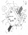
- Figure 1 illustrates a cross-head die assembly 100 connected to the gear pump or extruder assembly G shown in phantom.
- the assembly G supplies the elastomeric material to the cross-head die assembly.
- a plurality of parallel reinforcement cords 110 enter the cross-head die assembly 100 and are encased with elastomeric material to form a strip of reinforced ply material 120 which is output from the outlet passageway 202 of the die 200.
- the strip has a typical width of 80 mm with a thickness of 1.2 mm.
- the cross-head die assembly 100 has an upper support block 130, a lower support block 140 and an interior section 150.
- An inlet section 160 is located on one end of the cross-head die assembly and is connected to the upper support block 130, the lower support block 140 and the interior section 150.
- the upper support block 130, lower support block 140 and the interior section are all removably connected to the assembly 100.
- FIG. 2 A cross-section of the cross-head die assembly 100 is shown in Figure 2 .
- the inlet section 160 has an inlet channel 162 for receiving elastomer material from an extruder (not shown) or extruder-gear pump assembly G.
- the inlet channel 162 communicates elastomer flow to a screen filter 164.
- the inlet section 160 is easily removed from the assembly 100 without the need to completely disassemble the die assembly in order to replace or access the screen filter 164.
- the screen filter 164 is easily removed and replaced.
- elastomer flow from the extruder enters the assembly 100 and is separated into an upper flow channel 170 and a lower flow channel 180.
- the upper flow channel 170 is formed from a removable upper insert plate 172 and a removable lower insert plate 174.
- the removable upper insert plate 172 ( Figure 5 ) has a 90 degree flow path 176 that cooperates with the 90 degree flow path 178 ( Figure 6 ) of the lower insert plate 184 to form the upper flow channel 170.
- the lower flow channel 180 is formed between a removable upper insert plate 182 ( Figure 2 ) and a lower insert plate 184 with 90 degree flow paths that cooperate to form the lower flow channel 180.
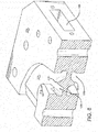
- the inlet to the upper and lower flow channel 170, 180 has a raised center rib 310,312 positioned at the entrance of each flow channel (i.e., there are two raised center ribs 310,312).
- This raised center rib 310 encourages the rubber flow to be directed to the inner edges 312 and outer edges 314 of the flow channel.
- the inner edge 312 has an enlarged radius.
- the raised center rib 310 is preferably V shaped.
- each flow channel has a bulbous extension 316 that has a large radius R in the range of 20 to 50 inches, more preferably 25 to 35 inches.
- the bulbous extension 316 helps to direct the rubber flow more towards the outside edge 314 then the inside edge 312, as well as to increase the velocity of the flow.
- the area of section A1 is greater than the area of section A2, while the area of section A2 is greater than the area of section A3, and the area of section A3 is greater than section A4.
- the area ratio of A4/A1 is in the range of from 0.80 to 0.99, and more preferably 0.85-0.99.
- the depth of the flow channel 170 is greater at the inlet than the outlet.
- the depth of the flow channel decreases from the inlet to the outlet.
- the width of the flow channel varies from entry to exit, initially decreasing than increasing near the exit.
- Cross sectional area is the important feature that decreases from entry to exit.
- the lower insert plate 174 and the upper insert plate 182 have a tapered outlet end 173, 183( Figure 3 ).
- the elastomer flow from the upper and lower flow channel 170, 180 enters the profile die 200.
- the profile die 200 is removably mounted to the cross-head assembly 100. As shown in Figure 1 , the profile die 200 has an outlet hole 202 for exit of the ply strip from the assembly 100.
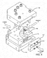
- the cross-head die assembly 100 has a removable cassette 400 for feeding the reinforcement cords 110 into the cross-head die assembly in parallel alignment.
- the cassette 400 is received in a rectangular shaped slot 402 located in interior section 150.
- the rectangular slot 402 extends from the inlet side 402 of the cross-head die assembly to the outlet side 404.
- the slot 402 is separated and isolated from the elastomer flow in the upper and lower flow channels 170, 180.
- the slot has upper and lower walls 410, 412 and first and second sidewalls 414, 416 which isolate the cassette and therefore allows the cassette to be removed from the assembly without disruption of the elastomer flow.
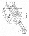
- Figure 10 illustrates the cords 110 in the cassette 400.
- the cords 110 are threaded in the slot 451 of cord guide 450.
- the front end of the cassette has a nose 460 that is detachable from the cassette.
- the nose 460 has a row of closely spaced outlet holes 462, wherein each hole 462 receives a cord.
- the outlet holes 462 are positioned adjacent to a lip 471 which protrudes axially from the outer surface of the nose.
- the lip 471 is formed by the removal or relief of a portion of the upper surface of the nose.
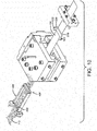
- a plurality of alignment grooves 464 are positioned on the lip 471 adjacent each outlet hole 462. The alignment groove 464 extends through the hole as shown in Figures 12, 13 and 16.
- the alignment grooves 464 together with the outlet holes 462 maintain the proper separation, spacing and alignment of each individual cord so that the reinforcement ply strip is formed with parallel and properly spaced cords as shown in Figure 11C. Further, the individual holes for each cord allow for the easy replacement of a single broken cord without disrupting the remaining cords.
- the nose 460 of the cassette is positioned adjacent the die assembly 200.
- the die assembly 200 further includes an insert 500 which is pressed into the die assembly, and is not held in place by any fasteners. It includes threaded holes to allow jack bolts for removal.
- the insert has flanged ends 502 which are positioned in the slot ends 506.
- the insert 500 has a front sealing edge 510 that is positioned in the insert slot 504. The insert 500 functions to seal the die edges to prevent leakage, particularly near the edges of the die. As pressure increases in the die assembly, the insert is pushed further into the die, resulting in the insert sealing edge 510 forming a seal with the die.
- the nose 460 of the cassette has an upper and lower outer contoured surface 461, 465.
- the upper contoured surface 461 of the nose is positioned adjacent the angled passageway 204.
- the elastomer flows down the upper outer surface of the nose, and then meets the cords at the lip 471 and encapsulates the reinforcement cords 110 along the lip 471.
- the alignment grooves 464 of the lip 471 maintain stability by retaining the cord spacing and alignment while the elastomer flows onto the cords.
- the flow from the bottom channel flows along the bottom surface of the nose and meets the cord after the upper portion of the cords have already been coated with rubber.
- the elastomer and cords then pass through the angled passageway 204 and then through the die outlet hole 202.
- the die 200 is removable to allow for easier cord threading. If a cord breaks or the cords need to be changed out, the cassette can be easily removed from the assembly.
- the die 200 and insert 500 can also be removed for cord change. If a cord is broken, it can be rethreaded into the guide 450 and the outlet hole 462 of the cassette. A broken cord can be replaced without rethreading the remaining cords.
- the rubber or elastomer remains isolated in the flow channels. A complete change out of the cord package may occur within 5 minutes.
- the flow channel inserts may also be changed out.
- the cross-head die assembly 100 may further comprise one or more cooling/heating channels 300 with a coolant inlet 302 and coolant exit 304.
- the improved cross-head die assembly provides for individually fed cord strands captured with through hole guide, with no sharp edges to break the cords.
- the assembly allows for easy change out of a cord package in minutes while the elastomer remains isolated in the flow channels. A broken cord can be replaced without the need to rethread all of the remaining cords.
- the assembly further provides for an integrated screen filter and replaceable flow channel inserts which allow the flow balance of the system to be modified.
Landscapes
- Engineering & Computer Science (AREA)
- Mechanical Engineering (AREA)
- Textile Engineering (AREA)
- Manufacturing & Machinery (AREA)
- Extrusion Moulding Of Plastics Or The Like (AREA)
- Tyre Moulding (AREA)
Claims (15)
- Querspritzkopfanordnung zur Verwendung mit einem Extruder, wobei die Querspritzkopfanordnung (100) umfasst:einen Einlassbereich (160), der einen Einlass zum Aufnehmen von Strömung von dem Extruder aufweist;einen oberen Stützblock (130), der mit einer ersten Seite eines Innenbereichs (150) entfernbar verbunden ist;einen unteren Stützblock (150), der mit einer zweiten Seite des Innenbereichs (150) entfernbar verbunden ist;einen ersten Strömungskanal (170), der sich zwischen dem oberen Stützblock (130) und dem Innenbereich (150) befindet und mit dem Einlass in Fluidverbindung steht;einen zweiten Strömungskanal (180), der sich zwischen dem Innenbereich (150) und dem unteren Stützblock (150) befindet und mit dem Einlass in Fluidverbindung steht;wobei die Querspritzkopfanordnung (100) ferner einen entfernbar montierten Kopf (200) umfasst, der sich an einem Auslassende der Anordnung (100) befindet;wobei der erste und der zweite Strömungskanal (170, 180) in Fluidverbindung mit einem Einlass des Kopfes (200) stehen; undwobei der Innenbereich (150) ferner einen Innenschlitz (402) umfasst, der sich von einer ersten Seite der Anordnung (100) zu dem Einlass des Kopfes (200) erstreckt;dadurch gekennzeichnet, dass der erste und der zweite Strömungskanal (170, 180) jeweils ein Einlassende und eine erhabene Mittelrippe (310, 312) aufweisen, die an dem Einlassende positioniert sind.
- Querspritzkopfanordnung nach Anspruch 1, wobei die Einlassfläche jedes Strömungskanals (170, 180) größer als die Auslassfläche jedes Strömungskanals (170, 180) ist.
- Querspritzkopfanordnung nach Anspruch 1 oder 2, wobei eine Tiefe jedes Strömungskanals (170, 180) von dem Einlassende zu dem Auslassende abnimmt.
- Querspritzkopfanordnung nach wenigstens einem der vorhergehenden Ansprüche, wobei jeder Strömungskanal (170, 180) eine Innenkante aufweist, die einen kugelförmigen Vorsprung (316) aufweist.
- Querspritzkopfanordnung nach wenigstens einem der vorhergehenden Ansprüche, wobei das Flächenverhältnis des Ausgangs zu dem Einlass in dem Bereich von 0,8 bis 0,98, vorzugsweise von 0,9 bis 0,96, liegt.
- Querspritzkopfanordnung nach wenigstens einem der vorhergehenden Ansprüche, wobei die Breite des Strömungskanals (170, 180) von dem Einlass zu dem Auslass zunimmt.
- Querspritzkopfanordnung nach wenigstens einem der vorhergehenden Ansprüche, die ferner eine entfernbare Kassette (400) umfasst, die in dem Innenschlitz (402) positioniert ist.
- Querspritzkopfanordnung nach wenigstens einem der vorhergehenden Ansprüche, wobei der obere Stützblock (130) einen entfernbaren Strömungseinsatz aufweist und/oder der untere Stützblock (170) einen entfernbaren Strömungseinsatz aufweist.
- Querspritzkopfanordnung nach wenigstens einem der vorhergehenden Ansprüche, wobei die erste Seite des Innenbereichs (150) einen entfernbaren Strömungseinsatz aufweist und/oder die zweite Seite des Innenbereichs (150) einen entfernbaren Strömungseinsatz aufweist.
- Querspritzkopfanordnung nach wenigstens einem der vorhergehenden Ansprüche, wobei die Kassette (400) mehrere Löcher (462) zum Aufnehmen einer Kordlage aufweist.
- Querspritzkopfanordnung nach Anspruch 10, wobei jedes Loch (462) eine Ausrichtungsnut (464) aufweist, die sich durch das Loch erstreckt.
- Querspritzkopfanordnung nach wenigstens einem der vorhergehenden Ansprüche, wobei der Schlitz eine obere und eine untere Seitenwand und seitliche Seitenwände aufweist.
- Querspritzkopfanordnung nach wenigstens einem der vorhergehenden Ansprüche, wobei der Schlitz (402) ein Auslassende aufweist, wobei eine Nase (460) der Kassette (400) den Auslass des Schlitzes (402) gegen Strömung abdichtet, so dass der Schlitz (402) von der Strömung isoliert ist.
- Querspritzkopfanordnung nach wenigstens einem der vorhergehenden Ansprüche, wobei der Kopf (200) einen entfernbaren Einsatz (500) aufweist.
- Querspritzkopfanordnung nach Anspruch 9 oder 14, wobei der entfernbare Einsatz (500) eine Dichtungskante (510) aufweist, die gegen das Kopfauslassloch positioniert ist.
Applications Claiming Priority (1)
| Application Number | Priority Date | Filing Date | Title |
|---|---|---|---|
| US15/384,374 US20180169925A1 (en) | 2016-12-20 | 2016-12-20 | Apparatus for producing laminated fabric ply strips |
Publications (2)
| Publication Number | Publication Date |
|---|---|
| EP3338996A1 EP3338996A1 (de) | 2018-06-27 |
| EP3338996B1 true EP3338996B1 (de) | 2021-11-10 |
Family
ID=60781610
Family Applications (1)
| Application Number | Title | Priority Date | Filing Date |
|---|---|---|---|
| EP17207762.0A Active EP3338996B1 (de) | 2016-12-20 | 2017-12-15 | Vorrichtung zur herstellung von streifen aus laminierten stofflagen |
Country Status (5)
| Country | Link |
|---|---|
| US (1) | US20180169925A1 (de) |
| EP (1) | EP3338996B1 (de) |
| JP (1) | JP6994927B2 (de) |
| CN (1) | CN108202490B (de) |
| BR (1) | BR102017026898B1 (de) |
Families Citing this family (2)
| Publication number | Priority date | Publication date | Assignee | Title |
|---|---|---|---|---|
| EP3815891B1 (de) * | 2019-10-30 | 2023-05-17 | The Goodyear Tire & Rubber Company | Matrize für eine polymermisch- oder lagenherstellungsmaschine, kord- oder kehllage und ihre verwendung, verfahren zur herstellung einer solchen lage und reifen mit einer solchen lage |
| CN113844003B (zh) * | 2021-06-30 | 2023-08-15 | 桂林橡胶设计院有限公司 | 一种液压轮胎零度带束层挤出机头 |
Family Cites Families (17)
| Publication number | Priority date | Publication date | Assignee | Title |
|---|---|---|---|---|
| US3590432A (en) * | 1968-12-19 | 1971-07-06 | Gloucester Eng Co Inc | Rotary assembly for molten plastic |
| IT1045860B (it) * | 1972-08-25 | 1980-06-10 | Windmoeller & Hoelscher | Testa di soffiaggio per la produzione di tubolari in plastica |
| FR2272821B1 (de) * | 1974-02-20 | 1977-11-18 | Miyazaki Hachiro | |
| US4150929A (en) * | 1977-06-22 | 1979-04-24 | B & H Tool Company, Inc. | Ribbon cable extrusion apparatus |
| US4274821A (en) * | 1980-02-28 | 1981-06-23 | The Steelastic Company | Die for extruding reinforced fabric |
| US4563140A (en) * | 1983-11-14 | 1986-01-07 | Armstrong Rubber Company | Apparatus for coating aligned cords |
| IT1219242B (it) * | 1988-04-27 | 1990-05-03 | Firestone Int Dev Spa | Testa di estrusione per materiale in foglio internamente armato con elementi in filo di rinforzo distribuiti con passo relativamente ridotto |
| IT1245462B (it) * | 1991-03-15 | 1994-09-20 | Firestone Int Dev Spa | Testa di estrusione per la realizzazione di fasce armate per pneumatici di veicoli stradali |
| US5382401A (en) * | 1993-08-10 | 1995-01-17 | General Motors Corporation | Extrusion die stabilizer guide and method of extrusion |
| US6884823B1 (en) * | 1997-01-16 | 2005-04-26 | Trexel, Inc. | Injection molding of polymeric material |
| US20020134481A1 (en) * | 2001-03-20 | 2002-09-26 | Abdallah David G. | Radial tire having a wrapped body ply with two rows of reinforcement cords |
| US7056110B2 (en) * | 2001-10-08 | 2006-06-06 | Bridgestone/Firestone North American Tire, Llc | Apparatus for making reinforcement ply material |
| US7318720B2 (en) * | 2003-08-07 | 2008-01-15 | Arunas Antanas Pabedinskas | Die assembly and production process for profile extrusion |
| CN102689431B (zh) * | 2012-06-19 | 2015-05-20 | 淮海工学院 | 一种软硬塑料异型材共挤出模具 |
| US9770859B2 (en) * | 2014-12-18 | 2017-09-26 | The Goodyear Tire & Rubber Company | Apparatus for producing laminated fabric ply strips |
| US9616623B2 (en) * | 2015-03-04 | 2017-04-11 | Ebert Composites Corporation | 3D thermoplastic composite pultrusion system and method |
| NL2014634B1 (en) * | 2015-04-14 | 2016-12-20 | Vmi Holland Bv | Extruder system for extruding cord reinforced extrudate. |
-
2016
- 2016-12-20 US US15/384,374 patent/US20180169925A1/en not_active Abandoned
-
2017
- 2017-12-13 BR BR102017026898-5A patent/BR102017026898B1/pt not_active IP Right Cessation
- 2017-12-15 EP EP17207762.0A patent/EP3338996B1/de active Active
- 2017-12-19 JP JP2017242935A patent/JP6994927B2/ja active Active
- 2017-12-20 CN CN201711385960.4A patent/CN108202490B/zh active Active
Also Published As
| Publication number | Publication date |
|---|---|
| CN108202490B (zh) | 2021-03-30 |
| BR102017026898A2 (pt) | 2018-12-18 |
| CN108202490A (zh) | 2018-06-26 |
| BR102017026898A8 (pt) | 2022-09-13 |
| JP2018099886A (ja) | 2018-06-28 |
| EP3338996A1 (de) | 2018-06-27 |
| JP6994927B2 (ja) | 2022-02-04 |
| US20180169925A1 (en) | 2018-06-21 |
| BR102017026898B1 (pt) | 2022-10-11 |
Similar Documents
| Publication | Publication Date | Title |
|---|---|---|
| EP2995439B1 (de) | Vorrichtung und verfahren zur herstellung von streifen aus laminierten stofflagen | |
| EP3034268A1 (de) | Vorrichtung zur herstellung von streifen aus laminierten stofflagen | |
| US4892473A (en) | Head for extrusion of elastomeric contour innerliner | |
| JPH0564087B2 (de) | ||
| EP3037241B1 (de) | Extrudermundstückanordnung und verfahren zur herstellung einer reifenlauffläche | |
| EP0046688B1 (de) | Extrusionsdüse | |
| EP0164365B1 (de) | Vorrichtung zum beschichten ausgerichteter teile | |
| EP3338996A1 (de) | Vorrichtung zur herstellung von streifen aus laminierten stofflagen | |
| RU2728999C2 (ru) | Экструзионная головка для экструзии армированного кордом экструдата | |
| US7056110B2 (en) | Apparatus for making reinforcement ply material | |
| EP3248753B1 (de) | Kreuzkopfdüse und verfahren zum extrudieren eines profils unter verwendung solch einer kreuzkopfdüse | |
| EP3815891B1 (de) | Matrize für eine polymermisch- oder lagenherstellungsmaschine, kord- oder kehllage und ihre verwendung, verfahren zur herstellung einer solchen lage und reifen mit einer solchen lage | |
| KR101952201B1 (ko) | 고무 압출 부재의 제조 방법 및 제조 장치 | |
| US20020134481A1 (en) | Radial tire having a wrapped body ply with two rows of reinforcement cords | |
| KR102719274B1 (ko) | 타이어 캡플라이용 인서트다이 및 이를 이용한 피착물 | |
| KR101923295B1 (ko) | 캡플라이 압출장치 | |
| US20170173837A1 (en) | Extruder die assembly |
Legal Events
| Date | Code | Title | Description |
|---|---|---|---|
| PUAI | Public reference made under article 153(3) epc to a published international application that has entered the european phase |
Free format text: ORIGINAL CODE: 0009012 |
|
| STAA | Information on the status of an ep patent application or granted ep patent |
Free format text: STATUS: THE APPLICATION HAS BEEN PUBLISHED |
|
| AK | Designated contracting states |
Kind code of ref document: A1 Designated state(s): AL AT BE BG CH CY CZ DE DK EE ES FI FR GB GR HR HU IE IS IT LI LT LU LV MC MK MT NL NO PL PT RO RS SE SI SK SM TR |
|
| AX | Request for extension of the european patent |
Extension state: BA ME |
|
| STAA | Information on the status of an ep patent application or granted ep patent |
Free format text: STATUS: REQUEST FOR EXAMINATION WAS MADE |
|
| 17P | Request for examination filed |
Effective date: 20190102 |
|
| RBV | Designated contracting states (corrected) |
Designated state(s): AL AT BE BG CH CY CZ DE DK EE ES FI FR GB GR HR HU IE IS IT LI LT LU LV MC MK MT NL NO PL PT RO RS SE SI SK SM TR |
|
| REG | Reference to a national code |
Ref country code: DE Ref legal event code: R079 Ref document number: 602017049031 Country of ref document: DE Free format text: PREVIOUS MAIN CLASS: B29C0047280000 Ipc: B29C0048340000 |
|
| GRAP | Despatch of communication of intention to grant a patent |
Free format text: ORIGINAL CODE: EPIDOSNIGR1 |
|
| STAA | Information on the status of an ep patent application or granted ep patent |
Free format text: STATUS: GRANT OF PATENT IS INTENDED |
|
| RIC1 | Information provided on ipc code assigned before grant |
Ipc: B29C 48/34 20190101AFI20210507BHEP Ipc: B29C 48/156 20190101ALI20210507BHEP Ipc: B29C 48/25 20190101ALI20210507BHEP Ipc: B29C 48/21 20190101ALI20210507BHEP Ipc: B29C 48/07 20190101ALN20210507BHEP Ipc: B29D 30/38 20060101ALN20210507BHEP |
|
| INTG | Intention to grant announced |
Effective date: 20210602 |
|
| GRAS | Grant fee paid |
Free format text: ORIGINAL CODE: EPIDOSNIGR3 |
|
| GRAA | (expected) grant |
Free format text: ORIGINAL CODE: 0009210 |
|
| STAA | Information on the status of an ep patent application or granted ep patent |
Free format text: STATUS: THE PATENT HAS BEEN GRANTED |
|
| AK | Designated contracting states |
Kind code of ref document: B1 Designated state(s): AL AT BE BG CH CY CZ DE DK EE ES FI FR GB GR HR HU IE IS IT LI LT LU LV MC MK MT NL NO PL PT RO RS SE SI SK SM TR |
|
| REG | Reference to a national code |
Ref country code: GB Ref legal event code: FG4D |
|
| REG | Reference to a national code |
Ref country code: AT Ref legal event code: REF Ref document number: 1445668 Country of ref document: AT Kind code of ref document: T Effective date: 20211115 Ref country code: CH Ref legal event code: EP |
|
| REG | Reference to a national code |
Ref country code: DE Ref legal event code: R096 Ref document number: 602017049031 Country of ref document: DE |
|
| REG | Reference to a national code |
Ref country code: IE Ref legal event code: FG4D |
|
| REG | Reference to a national code |
Ref country code: LT Ref legal event code: MG9D |
|
| REG | Reference to a national code |
Ref country code: NL Ref legal event code: MP Effective date: 20211110 |
|
| REG | Reference to a national code |
Ref country code: AT Ref legal event code: MK05 Ref document number: 1445668 Country of ref document: AT Kind code of ref document: T Effective date: 20211110 |
|
| PG25 | Lapsed in a contracting state [announced via postgrant information from national office to epo] |
Ref country code: RS Free format text: LAPSE BECAUSE OF FAILURE TO SUBMIT A TRANSLATION OF THE DESCRIPTION OR TO PAY THE FEE WITHIN THE PRESCRIBED TIME-LIMIT Effective date: 20211110 Ref country code: LT Free format text: LAPSE BECAUSE OF FAILURE TO SUBMIT A TRANSLATION OF THE DESCRIPTION OR TO PAY THE FEE WITHIN THE PRESCRIBED TIME-LIMIT Effective date: 20211110 Ref country code: FI Free format text: LAPSE BECAUSE OF FAILURE TO SUBMIT A TRANSLATION OF THE DESCRIPTION OR TO PAY THE FEE WITHIN THE PRESCRIBED TIME-LIMIT Effective date: 20211110 Ref country code: BG Free format text: LAPSE BECAUSE OF FAILURE TO SUBMIT A TRANSLATION OF THE DESCRIPTION OR TO PAY THE FEE WITHIN THE PRESCRIBED TIME-LIMIT Effective date: 20220210 Ref country code: AT Free format text: LAPSE BECAUSE OF FAILURE TO SUBMIT A TRANSLATION OF THE DESCRIPTION OR TO PAY THE FEE WITHIN THE PRESCRIBED TIME-LIMIT Effective date: 20211110 |
|
| PG25 | Lapsed in a contracting state [announced via postgrant information from national office to epo] |
Ref country code: IS Free format text: LAPSE BECAUSE OF FAILURE TO SUBMIT A TRANSLATION OF THE DESCRIPTION OR TO PAY THE FEE WITHIN THE PRESCRIBED TIME-LIMIT Effective date: 20220310 Ref country code: SE Free format text: LAPSE BECAUSE OF FAILURE TO SUBMIT A TRANSLATION OF THE DESCRIPTION OR TO PAY THE FEE WITHIN THE PRESCRIBED TIME-LIMIT Effective date: 20211110 Ref country code: PT Free format text: LAPSE BECAUSE OF FAILURE TO SUBMIT A TRANSLATION OF THE DESCRIPTION OR TO PAY THE FEE WITHIN THE PRESCRIBED TIME-LIMIT Effective date: 20220310 Ref country code: PL Free format text: LAPSE BECAUSE OF FAILURE TO SUBMIT A TRANSLATION OF THE DESCRIPTION OR TO PAY THE FEE WITHIN THE PRESCRIBED TIME-LIMIT Effective date: 20211110 Ref country code: NO Free format text: LAPSE BECAUSE OF FAILURE TO SUBMIT A TRANSLATION OF THE DESCRIPTION OR TO PAY THE FEE WITHIN THE PRESCRIBED TIME-LIMIT Effective date: 20220210 Ref country code: NL Free format text: LAPSE BECAUSE OF FAILURE TO SUBMIT A TRANSLATION OF THE DESCRIPTION OR TO PAY THE FEE WITHIN THE PRESCRIBED TIME-LIMIT Effective date: 20211110 Ref country code: LV Free format text: LAPSE BECAUSE OF FAILURE TO SUBMIT A TRANSLATION OF THE DESCRIPTION OR TO PAY THE FEE WITHIN THE PRESCRIBED TIME-LIMIT Effective date: 20211110 Ref country code: HR Free format text: LAPSE BECAUSE OF FAILURE TO SUBMIT A TRANSLATION OF THE DESCRIPTION OR TO PAY THE FEE WITHIN THE PRESCRIBED TIME-LIMIT Effective date: 20211110 Ref country code: GR Free format text: LAPSE BECAUSE OF FAILURE TO SUBMIT A TRANSLATION OF THE DESCRIPTION OR TO PAY THE FEE WITHIN THE PRESCRIBED TIME-LIMIT Effective date: 20220211 Ref country code: ES Free format text: LAPSE BECAUSE OF FAILURE TO SUBMIT A TRANSLATION OF THE DESCRIPTION OR TO PAY THE FEE WITHIN THE PRESCRIBED TIME-LIMIT Effective date: 20211110 |
|
| PG25 | Lapsed in a contracting state [announced via postgrant information from national office to epo] |
Ref country code: SM Free format text: LAPSE BECAUSE OF FAILURE TO SUBMIT A TRANSLATION OF THE DESCRIPTION OR TO PAY THE FEE WITHIN THE PRESCRIBED TIME-LIMIT Effective date: 20211110 Ref country code: SK Free format text: LAPSE BECAUSE OF FAILURE TO SUBMIT A TRANSLATION OF THE DESCRIPTION OR TO PAY THE FEE WITHIN THE PRESCRIBED TIME-LIMIT Effective date: 20211110 Ref country code: RO Free format text: LAPSE BECAUSE OF FAILURE TO SUBMIT A TRANSLATION OF THE DESCRIPTION OR TO PAY THE FEE WITHIN THE PRESCRIBED TIME-LIMIT Effective date: 20211110 Ref country code: EE Free format text: LAPSE BECAUSE OF FAILURE TO SUBMIT A TRANSLATION OF THE DESCRIPTION OR TO PAY THE FEE WITHIN THE PRESCRIBED TIME-LIMIT Effective date: 20211110 Ref country code: DK Free format text: LAPSE BECAUSE OF FAILURE TO SUBMIT A TRANSLATION OF THE DESCRIPTION OR TO PAY THE FEE WITHIN THE PRESCRIBED TIME-LIMIT Effective date: 20211110 Ref country code: CZ Free format text: LAPSE BECAUSE OF FAILURE TO SUBMIT A TRANSLATION OF THE DESCRIPTION OR TO PAY THE FEE WITHIN THE PRESCRIBED TIME-LIMIT Effective date: 20211110 |
|
| REG | Reference to a national code |
Ref country code: CH Ref legal event code: PL |
|
| REG | Reference to a national code |
Ref country code: DE Ref legal event code: R097 Ref document number: 602017049031 Country of ref document: DE |
|
| PG25 | Lapsed in a contracting state [announced via postgrant information from national office to epo] |
Ref country code: MC Free format text: LAPSE BECAUSE OF FAILURE TO SUBMIT A TRANSLATION OF THE DESCRIPTION OR TO PAY THE FEE WITHIN THE PRESCRIBED TIME-LIMIT Effective date: 20211110 |
|
| PLBE | No opposition filed within time limit |
Free format text: ORIGINAL CODE: 0009261 |
|
| STAA | Information on the status of an ep patent application or granted ep patent |
Free format text: STATUS: NO OPPOSITION FILED WITHIN TIME LIMIT |
|
| REG | Reference to a national code |
Ref country code: BE Ref legal event code: MM Effective date: 20211231 |
|
| 26N | No opposition filed |
Effective date: 20220811 |
|
| GBPC | Gb: european patent ceased through non-payment of renewal fee |
Effective date: 20220210 |
|
| PG25 | Lapsed in a contracting state [announced via postgrant information from national office to epo] |
Ref country code: LU Free format text: LAPSE BECAUSE OF NON-PAYMENT OF DUE FEES Effective date: 20211215 Ref country code: IE Free format text: LAPSE BECAUSE OF NON-PAYMENT OF DUE FEES Effective date: 20211215 Ref country code: AL Free format text: LAPSE BECAUSE OF FAILURE TO SUBMIT A TRANSLATION OF THE DESCRIPTION OR TO PAY THE FEE WITHIN THE PRESCRIBED TIME-LIMIT Effective date: 20211110 |
|
| PG25 | Lapsed in a contracting state [announced via postgrant information from national office to epo] |
Ref country code: SI Free format text: LAPSE BECAUSE OF FAILURE TO SUBMIT A TRANSLATION OF THE DESCRIPTION OR TO PAY THE FEE WITHIN THE PRESCRIBED TIME-LIMIT Effective date: 20211110 Ref country code: BE Free format text: LAPSE BECAUSE OF NON-PAYMENT OF DUE FEES Effective date: 20211231 |
|
| PG25 | Lapsed in a contracting state [announced via postgrant information from national office to epo] |
Ref country code: LI Free format text: LAPSE BECAUSE OF NON-PAYMENT OF DUE FEES Effective date: 20211231 Ref country code: CH Free format text: LAPSE BECAUSE OF NON-PAYMENT OF DUE FEES Effective date: 20211231 |
|
| PG25 | Lapsed in a contracting state [announced via postgrant information from national office to epo] |
Ref country code: GB Free format text: LAPSE BECAUSE OF NON-PAYMENT OF DUE FEES Effective date: 20220210 |
|
| PG25 | Lapsed in a contracting state [announced via postgrant information from national office to epo] |
Ref country code: HU Free format text: LAPSE BECAUSE OF FAILURE TO SUBMIT A TRANSLATION OF THE DESCRIPTION OR TO PAY THE FEE WITHIN THE PRESCRIBED TIME-LIMIT; INVALID AB INITIO Effective date: 20171215 |
|
| PG25 | Lapsed in a contracting state [announced via postgrant information from national office to epo] |
Ref country code: CY Free format text: LAPSE BECAUSE OF FAILURE TO SUBMIT A TRANSLATION OF THE DESCRIPTION OR TO PAY THE FEE WITHIN THE PRESCRIBED TIME-LIMIT Effective date: 20211110 |
|
| PGFP | Annual fee paid to national office [announced via postgrant information from national office to epo] |
Ref country code: IT Payment date: 20231110 Year of fee payment: 7 |
|
| PG25 | Lapsed in a contracting state [announced via postgrant information from national office to epo] |
Ref country code: MK Free format text: LAPSE BECAUSE OF FAILURE TO SUBMIT A TRANSLATION OF THE DESCRIPTION OR TO PAY THE FEE WITHIN THE PRESCRIBED TIME-LIMIT Effective date: 20211110 |
|
| PG25 | Lapsed in a contracting state [announced via postgrant information from national office to epo] |
Ref country code: MT Free format text: LAPSE BECAUSE OF FAILURE TO SUBMIT A TRANSLATION OF THE DESCRIPTION OR TO PAY THE FEE WITHIN THE PRESCRIBED TIME-LIMIT Effective date: 20211110 |
|
| PG25 | Lapsed in a contracting state [announced via postgrant information from national office to epo] |
Ref country code: IT Free format text: LAPSE BECAUSE OF NON-PAYMENT OF DUE FEES Effective date: 20241215 |
|
| PG25 | Lapsed in a contracting state [announced via postgrant information from national office to epo] |
Ref country code: TR Free format text: LAPSE BECAUSE OF FAILURE TO SUBMIT A TRANSLATION OF THE DESCRIPTION OR TO PAY THE FEE WITHIN THE PRESCRIBED TIME-LIMIT Effective date: 20211110 |
|
| PGFP | Annual fee paid to national office [announced via postgrant information from national office to epo] |
Ref country code: DE Payment date: 20251126 Year of fee payment: 9 |
|
| PGFP | Annual fee paid to national office [announced via postgrant information from national office to epo] |
Ref country code: FR Payment date: 20251119 Year of fee payment: 9 |