EP3339064B1 - Kettenglied mit reibverschweisstem traktionselement, verfahren zu seiner herstellung und gleitschutz- oder reifenschutzvorrichtung mit einem solchen kettenglied - Google Patents
Kettenglied mit reibverschweisstem traktionselement, verfahren zu seiner herstellung und gleitschutz- oder reifenschutzvorrichtung mit einem solchen kettenglied Download PDFInfo
- Publication number
- EP3339064B1 EP3339064B1 EP17205662.4A EP17205662A EP3339064B1 EP 3339064 B1 EP3339064 B1 EP 3339064B1 EP 17205662 A EP17205662 A EP 17205662A EP 3339064 B1 EP3339064 B1 EP 3339064B1
- Authority
- EP
- European Patent Office
- Prior art keywords
- chain link
- traction element
- link body
- chain
- friction
- Prior art date
- Legal status (The legal status is an assumption and is not a legal conclusion. Google has not performed a legal analysis and makes no representation as to the accuracy of the status listed.)
- Active
Links
Images


Classifications
-
- B—PERFORMING OPERATIONS; TRANSPORTING
- B60—VEHICLES IN GENERAL
- B60C—VEHICLE TYRES; TYRE INFLATION; TYRE CHANGING; CONNECTING VALVES TO INFLATABLE ELASTIC BODIES IN GENERAL; DEVICES OR ARRANGEMENTS RELATED TO TYRES
- B60C27/00—Non-skid devices temporarily attachable to resilient tyres or resiliently-tyred wheels
- B60C27/06—Non-skid devices temporarily attachable to resilient tyres or resiliently-tyred wheels extending over the complete circumference of the tread, e.g. made of chains or cables
- B60C27/08—Non-skid devices temporarily attachable to resilient tyres or resiliently-tyred wheels extending over the complete circumference of the tread, e.g. made of chains or cables involving lugs or rings taking up wear, e.g. chain links, chain connectors
- B60C27/086—Studded links, i.e. traction enhancing parts located on the link or inserted into the link
-
- B—PERFORMING OPERATIONS; TRANSPORTING
- B29—WORKING OF PLASTICS; WORKING OF SUBSTANCES IN A PLASTIC STATE IN GENERAL
- B29C—SHAPING OR JOINING OF PLASTICS; SHAPING OF MATERIAL IN A PLASTIC STATE, NOT OTHERWISE PROVIDED FOR; AFTER-TREATMENT OF THE SHAPED PRODUCTS, e.g. REPAIRING
- B29C65/00—Joining or sealing of preformed parts, e.g. welding of plastics materials; Apparatus therefor
- B29C65/02—Joining or sealing of preformed parts, e.g. welding of plastics materials; Apparatus therefor by heating, with or without pressure
- B29C65/06—Joining or sealing of preformed parts, e.g. welding of plastics materials; Apparatus therefor by heating, with or without pressure using friction, e.g. spin welding
-
- B—PERFORMING OPERATIONS; TRANSPORTING
- B29—WORKING OF PLASTICS; WORKING OF SUBSTANCES IN A PLASTIC STATE IN GENERAL
- B29C—SHAPING OR JOINING OF PLASTICS; SHAPING OF MATERIAL IN A PLASTIC STATE, NOT OTHERWISE PROVIDED FOR; AFTER-TREATMENT OF THE SHAPED PRODUCTS, e.g. REPAIRING
- B29C65/00—Joining or sealing of preformed parts, e.g. welding of plastics materials; Apparatus therefor
- B29C65/02—Joining or sealing of preformed parts, e.g. welding of plastics materials; Apparatus therefor by heating, with or without pressure
- B29C65/06—Joining or sealing of preformed parts, e.g. welding of plastics materials; Apparatus therefor by heating, with or without pressure using friction, e.g. spin welding
- B29C65/0672—Spin welding
-
- B—PERFORMING OPERATIONS; TRANSPORTING
- B29—WORKING OF PLASTICS; WORKING OF SUBSTANCES IN A PLASTIC STATE IN GENERAL
- B29C—SHAPING OR JOINING OF PLASTICS; SHAPING OF MATERIAL IN A PLASTIC STATE, NOT OTHERWISE PROVIDED FOR; AFTER-TREATMENT OF THE SHAPED PRODUCTS, e.g. REPAIRING
- B29C66/00—General aspects of processes or apparatus for joining preformed parts
- B29C66/01—General aspects dealing with the joint area or with the area to be joined
- B29C66/05—Particular design of joint configurations
- B29C66/10—Particular design of joint configurations particular design of the joint cross-sections
- B29C66/11—Joint cross-sections comprising a single joint-segment, i.e. one of the parts to be joined comprising a single joint-segment in the joint cross-section
- B29C66/112—Single lapped joints
-
- B—PERFORMING OPERATIONS; TRANSPORTING
- B29—WORKING OF PLASTICS; WORKING OF SUBSTANCES IN A PLASTIC STATE IN GENERAL
- B29C—SHAPING OR JOINING OF PLASTICS; SHAPING OF MATERIAL IN A PLASTIC STATE, NOT OTHERWISE PROVIDED FOR; AFTER-TREATMENT OF THE SHAPED PRODUCTS, e.g. REPAIRING
- B29C66/00—General aspects of processes or apparatus for joining preformed parts
- B29C66/01—General aspects dealing with the joint area or with the area to be joined
- B29C66/05—Particular design of joint configurations
- B29C66/10—Particular design of joint configurations particular design of the joint cross-sections
- B29C66/11—Joint cross-sections comprising a single joint-segment, i.e. one of the parts to be joined comprising a single joint-segment in the joint cross-section
- B29C66/112—Single lapped joints
- B29C66/1122—Single lap to lap joints, i.e. overlap joints
-
- B—PERFORMING OPERATIONS; TRANSPORTING
- B29—WORKING OF PLASTICS; WORKING OF SUBSTANCES IN A PLASTIC STATE IN GENERAL
- B29C—SHAPING OR JOINING OF PLASTICS; SHAPING OF MATERIAL IN A PLASTIC STATE, NOT OTHERWISE PROVIDED FOR; AFTER-TREATMENT OF THE SHAPED PRODUCTS, e.g. REPAIRING
- B29C66/00—General aspects of processes or apparatus for joining preformed parts
- B29C66/01—General aspects dealing with the joint area or with the area to be joined
- B29C66/05—Particular design of joint configurations
- B29C66/10—Particular design of joint configurations particular design of the joint cross-sections
- B29C66/11—Joint cross-sections comprising a single joint-segment, i.e. one of the parts to be joined comprising a single joint-segment in the joint cross-section
- B29C66/114—Single butt joints
-
- B—PERFORMING OPERATIONS; TRANSPORTING
- B29—WORKING OF PLASTICS; WORKING OF SUBSTANCES IN A PLASTIC STATE IN GENERAL
- B29C—SHAPING OR JOINING OF PLASTICS; SHAPING OF MATERIAL IN A PLASTIC STATE, NOT OTHERWISE PROVIDED FOR; AFTER-TREATMENT OF THE SHAPED PRODUCTS, e.g. REPAIRING
- B29C66/00—General aspects of processes or apparatus for joining preformed parts
- B29C66/50—General aspects of joining tubular articles; General aspects of joining long products, i.e. bars or profiled elements; General aspects of joining single elements to tubular articles, hollow articles or bars; General aspects of joining several hollow-preforms to form hollow or tubular articles
- B29C66/51—Joining tubular articles, profiled elements or bars; Joining single elements to tubular articles, hollow articles or bars; Joining several hollow-preforms to form hollow or tubular articles
- B29C66/53—Joining single elements to tubular articles, hollow articles or bars
- B29C66/532—Joining single elements to the wall of tubular articles, hollow articles or bars
-
- B—PERFORMING OPERATIONS; TRANSPORTING
- B60—VEHICLES IN GENERAL
- B60C—VEHICLE TYRES; TYRE INFLATION; TYRE CHANGING; CONNECTING VALVES TO INFLATABLE ELASTIC BODIES IN GENERAL; DEVICES OR ARRANGEMENTS RELATED TO TYRES
- B60C27/00—Non-skid devices temporarily attachable to resilient tyres or resiliently-tyred wheels
- B60C27/02—Non-skid devices temporarily attachable to resilient tyres or resiliently-tyred wheels extending over restricted arcuate part of tread
- B60C27/0207—Non-skid devices temporarily attachable to resilient tyres or resiliently-tyred wheels extending over restricted arcuate part of tread involving lugs or rings taking up wear, e.g. chain links, chain connectors
- B60C27/0223—Studded links, i.e. traction enhancing parts located on the link or inserted into the link
-
- B—PERFORMING OPERATIONS; TRANSPORTING
- B23—MACHINE TOOLS; METAL-WORKING NOT OTHERWISE PROVIDED FOR
- B23K—SOLDERING OR UNSOLDERING; WELDING; CLADDING OR PLATING BY SOLDERING OR WELDING; CUTTING BY APPLYING HEAT LOCALLY, e.g. FLAME CUTTING; WORKING BY LASER BEAM
- B23K20/00—Non-electric welding by applying impact or other pressure, with or without the application of heat, e.g. cladding or plating
- B23K20/12—Non-electric welding by applying impact or other pressure, with or without the application of heat, e.g. cladding or plating the heat being generated by friction; Friction welding
- B23K20/129—Non-electric welding by applying impact or other pressure, with or without the application of heat, e.g. cladding or plating the heat being generated by friction; Friction welding specially adapted for particular articles or work
-
- B—PERFORMING OPERATIONS; TRANSPORTING
- B23—MACHINE TOOLS; METAL-WORKING NOT OTHERWISE PROVIDED FOR
- B23K—SOLDERING OR UNSOLDERING; WELDING; CLADDING OR PLATING BY SOLDERING OR WELDING; CUTTING BY APPLYING HEAT LOCALLY, e.g. FLAME CUTTING; WORKING BY LASER BEAM
- B23K2101/00—Articles made by soldering, welding or cutting
- B23K2101/30—Chains, hoops or rings
-
- B—PERFORMING OPERATIONS; TRANSPORTING
- B29—WORKING OF PLASTICS; WORKING OF SUBSTANCES IN A PLASTIC STATE IN GENERAL
- B29C—SHAPING OR JOINING OF PLASTICS; SHAPING OF MATERIAL IN A PLASTIC STATE, NOT OTHERWISE PROVIDED FOR; AFTER-TREATMENT OF THE SHAPED PRODUCTS, e.g. REPAIRING
- B29C65/00—Joining or sealing of preformed parts, e.g. welding of plastics materials; Apparatus therefor
- B29C65/02—Joining or sealing of preformed parts, e.g. welding of plastics materials; Apparatus therefor by heating, with or without pressure
- B29C65/06—Joining or sealing of preformed parts, e.g. welding of plastics materials; Apparatus therefor by heating, with or without pressure using friction, e.g. spin welding
- B29C65/0609—Joining or sealing of preformed parts, e.g. welding of plastics materials; Apparatus therefor by heating, with or without pressure using friction, e.g. spin welding characterised by the movement of the parts to be joined
- B29C65/0618—Linear
-
- B—PERFORMING OPERATIONS; TRANSPORTING
- B29—WORKING OF PLASTICS; WORKING OF SUBSTANCES IN A PLASTIC STATE IN GENERAL
- B29C—SHAPING OR JOINING OF PLASTICS; SHAPING OF MATERIAL IN A PLASTIC STATE, NOT OTHERWISE PROVIDED FOR; AFTER-TREATMENT OF THE SHAPED PRODUCTS, e.g. REPAIRING
- B29C65/00—Joining or sealing of preformed parts, e.g. welding of plastics materials; Apparatus therefor
- B29C65/02—Joining or sealing of preformed parts, e.g. welding of plastics materials; Apparatus therefor by heating, with or without pressure
- B29C65/06—Joining or sealing of preformed parts, e.g. welding of plastics materials; Apparatus therefor by heating, with or without pressure using friction, e.g. spin welding
- B29C65/0609—Joining or sealing of preformed parts, e.g. welding of plastics materials; Apparatus therefor by heating, with or without pressure using friction, e.g. spin welding characterised by the movement of the parts to be joined
- B29C65/0636—Orbital
-
- B—PERFORMING OPERATIONS; TRANSPORTING
- B29—WORKING OF PLASTICS; WORKING OF SUBSTANCES IN A PLASTIC STATE IN GENERAL
- B29C—SHAPING OR JOINING OF PLASTICS; SHAPING OF MATERIAL IN A PLASTIC STATE, NOT OTHERWISE PROVIDED FOR; AFTER-TREATMENT OF THE SHAPED PRODUCTS, e.g. REPAIRING
- B29C65/00—Joining or sealing of preformed parts, e.g. welding of plastics materials; Apparatus therefor
- B29C65/02—Joining or sealing of preformed parts, e.g. welding of plastics materials; Apparatus therefor by heating, with or without pressure
- B29C65/06—Joining or sealing of preformed parts, e.g. welding of plastics materials; Apparatus therefor by heating, with or without pressure using friction, e.g. spin welding
- B29C65/0609—Joining or sealing of preformed parts, e.g. welding of plastics materials; Apparatus therefor by heating, with or without pressure using friction, e.g. spin welding characterised by the movement of the parts to be joined
- B29C65/0636—Orbital
- B29C65/0645—Circular
-
- B—PERFORMING OPERATIONS; TRANSPORTING
- B29—WORKING OF PLASTICS; WORKING OF SUBSTANCES IN A PLASTIC STATE IN GENERAL
- B29C—SHAPING OR JOINING OF PLASTICS; SHAPING OF MATERIAL IN A PLASTIC STATE, NOT OTHERWISE PROVIDED FOR; AFTER-TREATMENT OF THE SHAPED PRODUCTS, e.g. REPAIRING
- B29C65/00—Joining or sealing of preformed parts, e.g. welding of plastics materials; Apparatus therefor
- B29C65/56—Joining or sealing of preformed parts, e.g. welding of plastics materials; Apparatus therefor using mechanical means or mechanical connections, e.g. form-fits
- B29C65/64—Joining a non-plastics element to a plastics element, e.g. by force
- B29C65/645—Joining a non-plastics element to a plastics element, e.g. by force using friction or ultrasonic vibrations
-
- B—PERFORMING OPERATIONS; TRANSPORTING
- B29—WORKING OF PLASTICS; WORKING OF SUBSTANCES IN A PLASTIC STATE IN GENERAL
- B29C—SHAPING OR JOINING OF PLASTICS; SHAPING OF MATERIAL IN A PLASTIC STATE, NOT OTHERWISE PROVIDED FOR; AFTER-TREATMENT OF THE SHAPED PRODUCTS, e.g. REPAIRING
- B29C66/00—General aspects of processes or apparatus for joining preformed parts
- B29C66/70—General aspects of processes or apparatus for joining preformed parts characterised by the composition, physical properties or the structure of the material of the parts to be joined; Joining with non-plastics material
- B29C66/74—Joining plastics material to non-plastics material
- B29C66/742—Joining plastics material to non-plastics material to metals or their alloys
-
- B—PERFORMING OPERATIONS; TRANSPORTING
- B29—WORKING OF PLASTICS; WORKING OF SUBSTANCES IN A PLASTIC STATE IN GENERAL
- B29L—INDEXING SCHEME ASSOCIATED WITH SUBCLASS B29C, RELATING TO PARTICULAR ARTICLES
- B29L2031/00—Other particular articles
- B29L2031/12—Chains
Definitions
- the invention relates to a chain link for an anti-skid or tire protection device, which has a chain link body and at least one traction element welded onto the chain link body and projecting from the chain link body. Furthermore, the invention relates to an anti-skid or tire protection device for a vehicle tire, with at least one chain strand which rests on a tread of the tire when the anti-skid or tire protection device is installed. Finally, the invention relates to a method for producing a chain link for an anti-skid or tire protection device.
- Anti-skid devices for example snow or forest chains, are said to improve the traction of the vehicle tire on slippery surfaces such as mud, mud, snow or ice.
- Tire protection chains serve to protect the tire carcass, whereby here too, sufficient traction must be ensured.
- a traction element onto the chain link body.
- the traction element protrudes from the chain link body and digs into the ground.
- Such a chain link is for example in the DE 20 2009 015 608 U1 described.
- the invention is therefore based on the object of providing a chain link for a tire protection or anti-skid device and a method for its production which is associated with less effort.
- WO 2009/080289 A1 a method for producing welded round and profile chains from interconnected chain links is shown. These are each made from two chain link sections which are connected to one another by friction welding, for example linear friction welding or orbital friction welding. Furthermore, these can be welded to one another by means of a so-called Friex process by means of a disk or plate, the plate or disk being located between the chain link sections.
- this object is achieved for the chain link mentioned at the outset in that the traction element is friction-welded.
- the object is achieved according to the invention in that at least one traction element is applied to a chain link body by means of friction welding.
- Friction welding has the advantage that it has greater flexibility than the resistance welding previously used to attach the traction elements to the chain link body. Different types of studs can be fully automated with the help of the friction welding process at the most different points of the chain link body and attached without much energy. Since the welding takes place without electrical current, it is safer to carry out. In addition, the heat input is locally very limited.
- the invention can be further improved by a series of further developments, each of which is advantageous and can be combined with one another as desired.
- the traction element can be rotationally, orbitally or linearly friction-welded.
- rotary friction welding the traction element is rotated about its own axis, which runs perpendicular to the welding surface.
- orbital friction welding the traction element or its axis moves on a circular path, whereby this orbital movement can also be superimposed by a rotational movement of the traction element about its own axis.
- linear friction welding the traction element is moved back and forth in a translatory manner. During these movements, the traction element is pressed against the chain link body, so that locally high frictional heat is generated. If the temperature on the surfaces of the traction element and chain link body rubbing against each other is sufficiently high, the movement is stopped and the contact pressure is increased, so that the traction element and chain link body weld.
- the traction element can in particular be tunnel-shaped or have a prismatic basic shape, a base surface of the prism preferably being welded to the chain link body.
- the traction element In the case of a rotationally orbitally welded traction element in particular, it is advisable to design the traction element with a rotationally symmetrical cross section or a rotationally symmetrical base surface forming the welding surface.
- the welding process is simplified compared to a polygonal base area with edges that can easily deform in the course of the friction welding process.
- the traction element can be made of a different, in particular harder, material than the chain link body in order to achieve a long service life.
- the chain link body itself can be assembled from two parts that are friction-welded together.
- the friction welding process enables different materials to be paired.
- one part can be made of a harder material than the other part.
- the production of the chain link can be simplified if the traction element is welded on before the two parts of the chain link body are joined together.
- the highly localized heat input during friction welding is particularly advantageous here, since the friction welding of the chain link body does not affect the clocking element or its connection to the chain link base body.
- the chain link body can have two legs connected to each other by a bend, one of the legs being reinforced compared to the other leg and the reinforced leg carrying the traction element.
- the reinforced leg forms a wear section that is continuously worn away by using the tire protection or anti-skid device.
- One of the parts joined to form the chain link body can have the thickened leg or consist of the thickened leg.
- the different features in the exemplary embodiments can be combined with one another as desired.
- a feature of an exemplary embodiment can be dispensed with if this feature has no technical effect that promises an advantage in a specific application.
- a feature from another embodiment can be added to one embodiment if this feature is important.
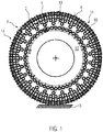
- Fig. 1 shows an example of a tire protection or anti-skid device 1, which is mounted on a vehicle tire 2, with at least some chain strands 4 coming to rest on a tread 6 of the vehicle tire 2.
- the tread 6 rolls on a surface 8, so that the chain strands 4 are located between the tread 6 and the surface 8.
- the tire or anti-skid device 1 cannot fall off the side of the vehicle tire 2, it extends over a tire flank 10 both on the outside 12 of the vehicle tire visible here and on that facing a vehicle body (not shown) in FIG Fig. 1 Inner side 14, not shown, of the vehicle tire 2.
- the chain strands 4 have chain links 16 which are provided with traction elements 18.
- Fig. 2 shows a single chain link 16 of a chain strand 4 ( Fig. 1 ).
- the chain link 16 has a chain link body 20 which can be assembled monolithically from two or more parts 22, 24, in particular by friction welding.
- the parts 22, 24 are preferably joined together by orbital or rotary friction welding.
- the chain link body 20 is a flat body with two opposite flat sides 26 which are connected to one another via narrow sides 28 of the chain link body 20.
- the chain link 16 is a standing chain link of the chain strand 4. This means that when the tire or anti-skid device is mounted, the chain link 16 rests with one of its narrow sides 28 on the tread 6 of the vehicle tire and thus its flat sides 26 are essentially perpendicular to the Extend tread 6.
- the narrow sides 28 can be formed by two essentially straight legs 30, wherein one of the legs 30 can rest on the running surface 6.
- the legs 30 are connected to one another by a more or less curved bend 32 of the chain link, which likewise form narrow sides 28.
- the bends 32 point in the direction of a longitudinal extension 34 of the chain strand 4, in which the chain links of the chain strand follow one another.
- One of the legs 30, and preferably the leg 30 on the side of the chain link 16 facing away from the tread, can be thickened.
- the at least one traction element can be attached to this leg.
- the thickened leg 30 is located on one part 22.
- the chain links (not shown) adjacent to the chain link 16 shown in the chain strand 4 are hooked into at least one opening 36 in the chain link 16.
- traction element 18 In order to increase the traction effect of the chain link 16, it is provided with at least one traction element 18. For example purposes only, in Fig. 2 two traction elements shown.
- the traction element 18 is preferably lug-shaped and protrudes from the chain link 16 in particular on its side facing away from the tread 6. In the case of a standing chain link, this side is a narrow side 28.
- a horizontal chain link can equally well be provided with at least one traction element 18.
- the flat sides 26 run essentially parallel to the running surface 6. Consequently, in the case of a lying chain link 16, the at least one traction element 18 can be attached to the flat side 26 pointing away from the running surface 6.
- the traction element 18 is friction welded to the chain link body 20.
- the traction element 18 can have a prismatic, in particular cylindrical shape with two opposite base surfaces 38, one of the base surfaces 38 being welded to the chain link body 20.
- a longitudinal axis 40 connects the two base surfaces 38 of the traction element 18.
- the cross section of the traction element is preferably rotationally symmetrical.
- the traction element 18 is rotated about the longitudinal axis 40 and pressed against the chain link body 20, so that frictional heat is generated. Due to the frictional heat, the material of the chain link body 20 and the traction element 18 on the abrading surfaces heats up to such an extent that the material becomes doughy and welded as soon as it is pressed together in the doughy state with the movement stopped.
- Orbital welding is also possible, in which the longitudinal axis 40 is guided along a circular path. In addition, this orbital movement can be connected to a rotation of the traction element 18 about its longitudinal axis 40.
- linear friction welding is also possible, in which the longitudinal axis 40 of the traction element 18 is moved back and forth in a translatory manner. Friction welding in particular also enables the pairing of materials that are otherwise difficult to bond to one another, such as plastics and metals, as well as metals of very different hardness or composition.
- the traction element 18 can accordingly be made of a different material, for example a different alloy than the chain link body 20.
- the traction element 18 is harder than the chain link body 20.
- the traction element 18 can be preassembled in the case of a multi-part chain link body 24, that is to say it can already be applied to the part 22 before it is joined to the part 24.
- the size, shape and number of the traction elements 18 and the chain link 16 can vary, as in the exemplary embodiments described below Figures 3 to 5 evident. For the sake of brevity, only the differences from the previous exemplary embodiments will be discussed in connection with these exemplary embodiments.
- Fig. 3 shows a chain link 16 with a single traction element 18 that extends in direction 34 over more than half a length 42 of chain link 16.
- the traction element 18 can have a smaller dimension perpendicular to the direction 34 than in the direction 34, so that it itself is elongated.
- Fig. 4 does not have the traction element 18, as in the embodiments of the 2 and 3 protrude vertically or almost perpendicularly from the tread 6, but can also clearly, be inclined between 30 ° and 60 ° with its longitudinal axis 40 relative to the tread 6 or the narrow side 28 or flat side 26 carrying the traction element 18.
- the inclination can run in the direction 34 and / or transversely thereto.
- block-shaped traction elements 18 can also be friction welded to the chain link body 20, the base area of the traction elements 18 being arbitrarily polygonal.
- the traction element can be attached at the transition between a narrow side 28 and a flat side 26.
Landscapes
- Engineering & Computer Science (AREA)
- Mechanical Engineering (AREA)
- Pressure Welding/Diffusion-Bonding (AREA)
Description
- Die Erfindung betrifft ein Kettenglied für eine Gleitschutz- oder Reifenschutzvorrichtung, das einen Kettengliedkörper und wenigstens ein auf den Kettengliedkörper aufgeschweißtes, vom Kettengliedkörper abstehendes Traktionselement aufweist. Ferner betrifft die Erfindung eine Gleitschutz- oder Reifenschutzvorrichtung für einen Fahrzeugreifen, mit wenigstens einem Kettenstrang, der bei montierter Gleitschutz- oder Reifenschutzvorrichtung auf einer Lauffläche des Reifens aufliegt. Schließlich betrifft die Erfindung ein Verfahren zum Herstellen eines Kettengliedes für eine Gleitschutz- oder Reifenschutzvorrichtung.
- Gleitschutzvorrichtungen, beispielsweise Schnee- oder Forstketten, sollen die Traktion des Fahrzeugreifens auf rutschigem Untergrund wie Schlamm, Matsch, Schnee oder Eis verbessern. Reifenschutzketten dienen dazu, die Reifenkarkasse zu schützen, wobei auch hier auf eine ausreichende Traktion geachtet werden muss.
- Zur Erhöhung der Traktion von Gleitschutz- oder Reifenschutzvorrichtungen ist es bekannt, ein Traktionselement auf den Kettengliedkörper aufzuschweißen. Das Traktionselement steht vom Kettengliedkörper ab und gräbt sich in den Untergrund ein. Ein derartiges Kettenglied ist beispielsweise in der
DE 20 2009 015 608 U1 beschrieben. - Die Herstellung des in dieser Druckschrift dargestellten Kettengliedes mit den Greifbolzen ist aufwändig.
- Der Erfindung liegt daher die Aufgabe zugrunde, ein Kettenglied für eine Reifenschutz- oder Gleitschutzvorrichtung sowie ein Verfahren zu seiner Herstellung zu schaffen, das mit weniger Aufwand verbunden ist.
- In der
WO 2009/080289 A1 ist ein Verfahren zur Herstellung geschweißter Rund- und Profilketten aus miteinander verbundenen Kettengliedern gezeigt. Diese werden jeweils aus zwei Kettenglied-Teilstücken hergestellt, die miteinander durch Reibschweißen, beispielsweise Linearreibschweißen oder Orbitalreibschweißen verbunden werden. Ferner können diese durch einen sogenannten Friex-Prozeß mittels einer Scheibe oder Platte miteinander verschweißt werden, wobei sich die Platte oder Scheibe zwischen den Kettenglied-Teilstücken befindet. - Erfindungsgemäß wird diese Aufgabe für das eingangs genannte Kettenglied dadurch gelöst, dass das Traktionselement reibverschweißt ist. Für das eingangs genannte Verfahren wird diese Aufgabe erfindungsgemäß dadurch gelöst, dass auf einen Kettengliedkörper wenigstens ein Traktionselement mittels Reibverschweißen aufgebracht wird.
- Das Reibverschweißen hat den Vorteil, dass es mit höherer Flexibilität als das bislang zur Anbringung der Traktionselemente auf dem Kettengliedkörper angewandte Widerstandsschweißen aufweist. Unterschiedlichste Stollenformen können mit Hilfe des Reibschweißverfahrens an den unterschiedlichsten Stellen des Kettengliedkörpers vollautomatisiert und ohne großen Energieaufwand angebracht werden. Da das Verschweißen ohne elektrischen Strom erfolgt, ist es sicherer durchzuführen. Außerdem ist der Wärmeeintrag lokal stark begrenzt.
- Die Erfindung kann durch eine Reihe von jeweils für sich vorteilhaften und beliebig miteinander kombinierbaren Weiterbildungen nochmals verbessert werden.
- So kann gemäß weiteren Ausgestaltungen das Traktionselement rotations-, orbital- oder linearreibverschweißt sein. Beim Rotationsreibschweißen wird das Traktionselement um seine eigene, senkrecht zur Schweißfläche verlaufende Achse gedreht. Beim Orbitalreibschweißen bewegt sich das Traktionselement bzw. dessen Achse auf einer Kreisbahn, wobei diese Orbitalbewegung auch von einer Rotationsbewegung des Traktionselements um seine eigene Achse überlagert sein kann. Beim Linearreibschweißen wird das Traktionselement translatorisch hin und her bewegt. Während dieser Bewegungen wird das Traktionselement gegen den Kettengliedkörper gedrückt, so dass eine lokal hohe Reibungswärme erzeugt wird. Ist die Temperatur an den aufeinanderreibenden Flächen von Traktionselement und Kettengliedkörper ausreichend hoch, wird die Bewegung gestoppt und der Anpressdruck erhöht, so dass Traktionselement und Kettengliedkörper verschweißen.
- Das Traktionselement kann insbesondere stollenförmig sein bzw. eine prismatische Grundform aufweisen, wobei bevorzugt eine Grundfläche des Prismas mit dem Kettengliedkörper verschweißt ist.
- Insbesondere bei einem rotations- oder orbitalverschweißten Traktionselement bietet es sich an, das Traktionselement mit einem rotationssymmetrischen Querschnitt bzw. einer rotationssymmetrischen, die Schweißfläche bildenden Grundfläche auszugestalten. Insbesondere bei einer eckenfreien Ausgestaltung der Grundfläche, insbesondere einer kreisförmigen Grundfläche, vereinfacht sich der Verschweißvorgang gegenüber einer polygonalen Grundfläche mit Kanten, die sich im Zuge des Reibschweißverfahrens leicht verformen können.
- Das Traktionselement kann aus einem anderen, insbesondere härterem Werkstoff als der Kettengliedkörper gefertigt sein, um hohe Standzeiten zu erreichen.
- Der Kettengliedkörper selbst kann aus zwei miteinander reibverschweißten Teilen zusammengefügt sein.
- Wie beim Stollen auch, ermöglicht das Reibschweißverfahren die Paarung unterschiedlicher Werkstoffe. So kann beispielsweise das eine Teil aus einem härteren Material bestehen als der andere Teil.
- Die Fertigung des Kettengliedes kann sich vereinfachen, wenn das Traktionselement vor dem Zusammenfügen der beiden Teile des Kettengliedkörpers aufgeschweißt wird. Insbesondere hier ist der stark lokalisierte Wärmeeintrag beim Reibschweißen von Vorteil, da sich die Reibverschweißung des Kettengliedkörpers nicht auf das Taktionselement bzw. seine Verbindung mit dem Kettengliedgrundkörper auswirkt.
- Der Kettengliedkörper kann gemäß einer weiteren Ausgestaltung zwei durch Buge miteinander verbundene Schenkel aufweisen, wobei einer der Schenkel gegenüber dem anderen Schenkel verstärkt ausgestaltet ist und der verstärkte Schenkel das Traktionselement trägt. Der verstärkte Schenkel bildet einen Verschleißabschnitt, der durch die Benutzung der Reifenschutz- oder Gleitschutzvorrichtung stetig abgetragen wird. Das eine der zum Kettengliedkörper zusammengefügten Teile kann den verdickten Schenkel aufweisen bzw. aus dem verdickten Schenkel bestehen.
- Die Erfindung ist im Folgenden anhand von Ausführungsbeispielen exemplarisch näher erläutert. In den Zeichnungen werden für Elemente, die einander hinsichtlich Funktion und/oder Aufbau entsprechen, dieselben Bezugszeichen verwendet.
- Nach Maßgabe der obigen Ausführungen können die bei den Ausführungsbeispielen unterschiedlichen Merkmale beliebig miteinander kombiniert werden. So kann beispielsweise auf ein Merkmal eines Ausführungsbeispiels verzichtet werden, wenn dieses Merkmal keinen technischen Effekt aufweist, der einen Vorteil bei einer bestimmten Anwendung verspricht. Umgekehrt kann einem Ausführungsbeispiel ein Merkmal von einem anderen Ausführungsbeispiel hinzugefügt werden, wenn es auf dieses Merkmal ankommt.
- Es zeigen:
- Fig. 1
- eine schematische Seitenansicht einer auf einem Fahrzeugreifen montierten Reifenschutz- oder Gleitschutzvorrichtung;
- Fig. 2
- eine schematische Perspektivdarstellung einer ersten Ausgestaltung eines erfindungsgemäßen Kettenglieds für eine Reifenschutz- oder Gleitschutzvorrichtung;
- Fig. 3
- eine schematische Perspektivdarstellung eines weiteren Ausführungsbeispiels eines erfindungsgemäßen Kettenglieds;
- Fig. 4
- eine schematische Perspektivdarstellung eines weiteren Ausführungsbeispiels eines erfindungsgemäßen Kettenglieds;
- Fig. 5
- eine schematische Perspektivdarstellung eines weiteren Ausführungsbeispiels eines Kettenglieds.
-
Fig. 1 zeigt beispielhaft eine Reifenschutz- oder Gleitschutzvorrichtung 1, die auf einem Fahrzeugreifen 2 montiert ist, wobei wenigstens einige Kettenstränge 4 auf einer Lauffläche 6 des Fahrzeugreifens 2 zu liegen kommen. Die Lauffläche 6 rollt auf einem Untergrund 8 ab, so dass sich die Kettenstränge 4 zwischen der Lauffläche 6 und dem Untergrund 8 befinden. - Damit die Reifen- oder Gleitschutzvorrichtung 1 nicht seitlich vom Fahrzeugreifen 2 abfallen kann, erstreckt sie sich über eine Reifenflanke 10 sowohl auf der hier sichtbaren Außenseite 12 des Fahrzeugreifens als auch auf der einer Fahrzeugkarosserie (nicht dargestellt) zugewandten, in
Fig. 1 nicht dargestellten Innenseite 14 des Fahrzeugreifens 2. - Die Kettenstränge 4 weisen Kettenglieder 16 auf, die mit Traktionselementen 18 versehen sind.
- Verschiedene beispielhafte Ausführungen der Kettenglieder 16, die gemeinsam oder alternativ in einer Reifen- oder Gleitschutzvorrichtung 1 bzw. einem Kettenstrang 4 verwendet werden können, sind im Folgenden mit Bezug auf die
Figuren 2 bis 5 näher beschrieben. -
Fig. 2 zeigt ein einzelnes Kettenglied 16 eines Kettenstranges 4 (Fig. 1 ). Das Kettenglied 16 weist einen Kettengliedkörper 20 auf, der aus zwei oder mehr Teilen 22, 24 insbesondere durch Reibverschweißen monolithisch zusammengefügt sein kann. Bevorzugt sind die Teile 22, 24 durch Orbital- oder Rotationsreibverschweißen stoffschlüssig zusammengefügt. - Der Kettengliedkörper 20 ist ein Flachkörper mit zwei sich gegenüberliegenden Flachseiten 26, die über Schmalseiten 28 des Kettengliedkörpers 20 miteinander verbunden sind.
- Das Kettenglied 16 ist in der dargestellten Ausgestaltung ein stehendes Kettenglied des Kettenstranges 4. Dies bedeutet, dass das Kettenglied 16 bei montierter Reifen- oder Gleitschutzvorrichtung mit einer seiner Schmalseiten 28 auf der Lauffläche 6 des Fahrzeugreifens aufliegt und sich somit seine Flachseiten 26 im Wesentlichen senkrecht zur Lauffläche 6 erstrecken.
- Die Schmalseiten 28 können von zwei im Wesentlichen geradlinigen Schenkeln 30 gebildet sein, wobei einer der Schenkel 30 auf der Lauffläche 6 aufliegen kann. Die Schenkel 30 sind durch mehr oder weniger gekrümmte Buge 32 des Kettengliedes miteinander verbunden, die ebenfalls Schmalseiten 28 bilden. Die Buge 32 weisen in Richtung einer Längserstreckung 34 des Kettenstranges 4, in der die Kettenglieder des Kettenstranges aufeinander folgen. Einer der Schenkel 30, und zwar bevorzugt der Schenkel 30 auf der von der Lauffläche abgewandten Seite des Kettengliedes 16, kann verdickt sein. An diesem Schenkel kann das wenigstens eine Traktionselement angebracht sein. Der verdickte Schenkel 30 befindet sich an dem einen Teil 22.
- Die im Kettenstrang 4 zu dem dargestellten Kettenglied 16 benachbarten Kettenglieder (nicht gezeigt) werden in wenigstens eine Öffnung 36 des Kettengliedes 16 eingehängt.
- Um die Traktionswirkung des Kettengliedes 16 zu erhöhen, ist es mit wenigstens einem Traktionselement 18 versehen. Lediglich zu Beispielzwecken sind in
Fig. 2 zwei Traktionselemente gezeigt. - Das Traktionselement 18 ist bevorzugt stollenförmig und steht vom Kettenglied 16 insbesondere an dessen von der Lauffläche 6 weg weisenden Seite ab. Bei einem stehenden Kettenglied ist diese Seite eine Schmalseite 28.
- Genauso gut kann jedoch ein liegendes Kettenglied mit wenigstens einem Traktionselement 18 versehen sein. Bei einem liegenden Kettenelement verlaufen die Flachseiten 26 im Wesentlichen parallel zur Lauffläche 6. Folglich kann bei einem liegenden Kettenglied 16 das wenigstens eine Traktionselement 18 an der von der Lauffläche 6 weg weisenden Flachseite 26 angebracht sein.
- Erfindungsgemäß ist das Traktionselement 18 mit dem Kettengliedkörper 20 reibverschweißt.
- Das Traktionselement 18 kann eine prismatische, insbesondere zylindrische Form mit zwei sich gegenüberliegenden Grundflächen 38 aufweisen, wobei eine der Grundflächen 38 mit dem Kettengliedkörper 20 verschweißt ist. Eine Längsachse 40 verbindet die beiden Grundflächen 38 des Traktionselements 18. Der Querschnitt des Traktionselements ist bevorzugt rotationssymmetrisch.
- Bei einer Rotationsverschweißung wird das Traktionselement 18 um die Längsachse 40 gedreht und dabei gegen den Kettengliedkörper 20 gedrückt, so dass Reibungswärme entsteht. Durch die Reibungswärme erhitzt sich das Material des Kettengliedkörpers 20 und des Traktionselements 18 an den aneinanderreibenden Flächen so stark, dass das Material teigig wird und verschweißt, sobald es im teigigen Zustand bei angehaltener Bewegung aneinandergepresst wird. Auch eine Orbitalverschweißung ist möglich, bei der die Längsachse 40 entlang einer Kreisbahn geführt wird. Zusätzlich kann diese Orbitalbewegung mit einer Rotation des Traktionselements 18 um seine Längsachse 40 verbunden sein. Schließlich ist auch eine Linearreibverschweißung möglich, bei der die Längsachse 40 des Traktionselements 18 translatorisch hin und her bewegt wird. Die Reibverschweißung ermöglicht insbesondere auch die Paarung von ansonsten nur schwer stoffschlüssig miteinander verbindbaren Werkstoffen, wie beispielsweise Kunststoffen und Metallen sowie Metallen stark unterschiedlicher Härte oder Zusammensetzung.
- Das Traktionselement 18 kann entsprechend aus einem anderen Werkstoff, beispielsweise einer anderen Legierung als der Kettengliedkörper 20 hergestellt sein. Insbesondere ist das Traktionselement 18 härter als der Kettengliedkörper 20.
- Das Traktionselement 18 kann bei einem mehrteiligen Kettengliedkörper 24 vormontiert sein, also bereits auf beispielsweise dem Teil 22 aufgebracht sein, bevor dieses mit dem Teil 24 zusammengefügt wird.
- Die Größe, Form und Anzahl der Traktionselemente 18 sowie des Kettengliedes 16 kann variieren, wie aus den nachstehend beschriebenen Ausführungsbeispielen der
Figuren 3 bis 5 hervorgeht. Der Kürze halber wird im Zusammenhang mit diesen Ausführungsbeispielen jeweils nur auf die Unterschiede zu den vorangegangenen Ausführungsbeispielen eingegangen. -
Fig. 3 zeigt beispielsweise ein Kettenglied 16 mit einem einzelnen Traktionselement 18, das sich über mehr als die Hälfte einer Länge 42 des Kettengliedes 16 in der Richtung 34 erstreckt. Das Traktionselement 18 kann senkrecht zur Richtung 34 eine geringere Abmessung aufweisen als in Richtung 34, so dass es selbst langgestreckt ist. - Gemäß
Fig. 4 muss das Traktionselement 18 nicht, wie bei den Ausführungsbeispielen derFig. 2 und 3 senkrecht oder nahezu senkrecht von der Lauffläche 6 abstehen, sondern kann auch deutlich, zwischen 30° und 60° mit seiner Längsachse 40 gegenüber der Lauffläche 6 bzw. der das Traktionselement 18 tragenden Schmalseite 28 oder Flachseite 26 geneigt sein. Die Neigung kann in Richtung 34 und/oder quer hierzu verlaufen. - Gemäß
Fig. 5 können auch quaderförmige Traktionselemente 18 mit dem Kettengliedkörper 20 reibverschweißt sein, wobei die Grundfläche der Traktionselemente 18 beliebig polygonal sein kann. - Weitere Abwandlungen sind möglich. So kann das Traktionselement am Übergang zwischen einer Schmalseite 28 und einer Flachseite 26 angebracht sein.
-
- 1
- Reifen- oder Gleitschutzvorrichtung
- 2
- Fahrzeugreifen
- 4
- Kettenstrang
- 6
- Lauffläche
- 8
- Untergrund
- 10
- Reifenflanke
- 12
- Außenseite
- 14
- Innenseite
- 16
- Kettenglied
- 18
- Traktionselement
- 20
- Kettengliedkörper
- 22
- Teil des Kettengliedkörpers
- 24
- Teil des Kettengliedkörpers
- 26
- Flachseite
- 28
- Schmalseite
- 30
- Schenkel
- 32
- Bug
- 34
- Längserstreckung
- 36
- Öffnung
- 38
- Grundfläche des Traktionselements
- 40
- Längsachse des Traktionselements
- 42
- Länge des Kettenglieds
Claims (13)
- Kettenglied (16) für eine Gleitschutz- oder Reifenschutzvorrichtung (1), das einen Kettengliedkörper (20) und wenigstens eine auf den Kettengliedkörper (20) aufgeschweißtes, vom Kettengliedkörper (20) abstehendes Traktionselement (18) aufweist, dadurch gekennzeichnet, dass das Traktionselement (18) reibverschweißt ist.
- Kettenglied (16) nach Anspruch 1, dadurch gekennzeichnet, dass das Traktionselement (18) rotationsreibverschweißt ist.
- Kettenglied (16) nach Anspruch 1, dadurch gekennzeichnet, dass das Traktionselement linearreibverschweißt ist.
- Kettenglied (16) nach Anspruch 1, dadurch gekennzeichnet, dass das Traktionselement (18) orbitalreibverschweißt ist.
- Kettenglied (16) nach einem der Ansprüche 1 bis 4, dadurch gekennzeichnet, dass der Kettengliedkörper (20) aus wenigstens zwei miteinander reibverschweißten Teilen (22, 24) zusammengefügt ist.
- Kettenglied (16) nach einem der Ansprüche 1 bis 5, dadurch gekennzeichnet, dass das wenigstens eine Traktionselement (18) einen rotationssymmetrischen Querschnitt aufweist.
- Kettenglied (16) nach einem der Ansprüche 1 bis 6, dadurch gekennzeichnet, dass der Kettengliedkörper (20) zwei durch Buge (32) miteinander verbundene Schenkel (30) aufweist, wobei einer der Schenkel (30) gegenüber dem anderen Schenkel (30) verstärkt ausgestaltet ist und das wenigstens eine Traktionselement (18) trägt.
- Kettenglied (16) nach Anspruch 7, dadurch gekennzeichnet, dass der verdickte Schenkel (30) mit dem übrigen Kettengliedkörper (20) stoffschlüssig zusammengefügt ist.
- Kettenglied (16) nach einem der Ansprüche 1 bis 8, dadurch gekennzeichnet, dass das Traktionselement (18) stollenförmig ist.
- Gleitschutz- oder Reifenschutzvorrichtung (1) für einen Fahrzeugreifen (2), mit wenigstens einem Kettenstrang (4), der bei montierter Gleitschutz- oder Reifenschutzvorrichtung (1) auf einer Lauffläche (6) des Fahrzeugreifens (2) aufliegt, dadurch gekennzeichnet, dass der Kettenstrang (4) wenigstens ein Kettenglied (16) nach einem der Ansprüche 1 bis 9 aufweist.
- Verfahren zum Herstellen eines Kettengliedes (16) für eine Gleitschutz- oder Reifenschutzvorrichtung (1), dadurch gekennzeichnet, dass auf einen Kettengliedkörper (20) des Kettengliedes (16) wenigstens ein Traktionselement (18) vom Kettengliedkörper (20) abstehend mittels Reibverschweißen aufgebracht wird.
- Verfahren nach Anspruch 11, dadurch gekennzeichnet, dass der Kettengliedkörper (20) aus wenigstens zwei Teilen (22, 24) mittels Reibverschweißen zusammengefügt wird.
- Verfahren nach Anspruch 12, dadurch gekennzeichnet, dass das Traktionselement (18) vor dem Zusammenfügen des Kettengliedkörpers (20) auf eines der Teile (22, 24) des Kettengliedkörpers (20) aufgebracht wird.
Applications Claiming Priority (1)
| Application Number | Priority Date | Filing Date | Title |
|---|---|---|---|
| DE102016226049.9A DE102016226049A1 (de) | 2016-12-22 | 2016-12-22 | Kettenglied mit reibverschweißtem Traktionselement, Verfahren zu seiner Herstellung und Gleitschutz- oder Reifenschutzvorrichtung mit einem solchen Kettenglied |
Publications (2)
| Publication Number | Publication Date |
|---|---|
| EP3339064A1 EP3339064A1 (de) | 2018-06-27 |
| EP3339064B1 true EP3339064B1 (de) | 2020-02-05 |
Family
ID=60582523
Family Applications (1)
| Application Number | Title | Priority Date | Filing Date |
|---|---|---|---|
| EP17205662.4A Active EP3339064B1 (de) | 2016-12-22 | 2017-12-06 | Kettenglied mit reibverschweisstem traktionselement, verfahren zu seiner herstellung und gleitschutz- oder reifenschutzvorrichtung mit einem solchen kettenglied |
Country Status (2)
| Country | Link |
|---|---|
| EP (1) | EP3339064B1 (de) |
| DE (1) | DE102016226049A1 (de) |
Cited By (1)
| Publication number | Priority date | Publication date | Assignee | Title |
|---|---|---|---|---|
| WO2026037502A1 (de) * | 2024-08-16 | 2026-02-19 | Rud Ketten Rieger & Dietz Gmbh U. Co. Kg | Traktionsglied mit klauenartig angeordneten traktionsvorsprüngen |
Families Citing this family (1)
| Publication number | Priority date | Publication date | Assignee | Title |
|---|---|---|---|---|
| DE102019209107A1 (de) * | 2019-06-24 | 2020-12-24 | Rud Ketten Rieger & Dietz Gmbh U. Co. Kg | Kettenstrang für eine Reifenkette und Verfahren zur Herstellung eines Kettenstrangs |
Family Cites Families (3)
| Publication number | Priority date | Publication date | Assignee | Title |
|---|---|---|---|---|
| NO325698B1 (no) * | 2005-06-13 | 2008-07-07 | Gunnebo Anja Ind As | Kjoretoykjetting. |
| DE102007061512A1 (de) * | 2007-12-20 | 2009-07-30 | Pewag Austria Gmbh | Verfahren zur Herstellung geschweißter Rund- und Profilketten, Kettenglied für eine Rund- oder Profilkette sowie aus solchen Kettengliedern aufgebaute Rund- oder Profilkette |
| DE202009015608U1 (de) | 2009-11-18 | 2010-03-04 | Rud Ketten Rieger & Dietz Gmbh &. Co. Kg | Gleitschutzkette mit Greifbolzen und Greifstegen |
-
2016
- 2016-12-22 DE DE102016226049.9A patent/DE102016226049A1/de not_active Withdrawn
-
2017
- 2017-12-06 EP EP17205662.4A patent/EP3339064B1/de active Active
Non-Patent Citations (1)
| Title |
|---|
| None * |
Cited By (1)
| Publication number | Priority date | Publication date | Assignee | Title |
|---|---|---|---|---|
| WO2026037502A1 (de) * | 2024-08-16 | 2026-02-19 | Rud Ketten Rieger & Dietz Gmbh U. Co. Kg | Traktionsglied mit klauenartig angeordneten traktionsvorsprüngen |
Also Published As
| Publication number | Publication date |
|---|---|
| EP3339064A1 (de) | 2018-06-27 |
| DE102016226049A1 (de) | 2018-06-28 |
Similar Documents
| Publication | Publication Date | Title |
|---|---|---|
| EP3728082B1 (de) | Mitnehmer für kettenkratzerförderer | |
| EP3339064B1 (de) | Kettenglied mit reibverschweisstem traktionselement, verfahren zu seiner herstellung und gleitschutz- oder reifenschutzvorrichtung mit einem solchen kettenglied | |
| EP3115640B1 (de) | Gurt oder gurtsegment | |
| EP2258566A1 (de) | Kettenglied für eine Gleitschutzkette | |
| EP2864137B1 (de) | Laufstreifenprofil eines fahrzeugreifens | |
| DE102012103944A1 (de) | Laufstreifenprofil eines Fahrzeugreifens | |
| DE202014103179U1 (de) | Plattenbandelement für eine als Traktionshilfe dienende, plattenbandförmige Gleiskette für Zwillingsachsen | |
| EP2852500B1 (de) | Laufstreifenprofil eines fahrzeugluftreifens | |
| EP3068679B1 (de) | Gummibandkettensegment | |
| DE102015224289A1 (de) | Fahrzeugluftreifen | |
| DE202014010830U1 (de) | Ratschenspannvorrichtung | |
| WO2017016677A1 (de) | Notlaufeinsatz | |
| EP3215410B1 (de) | Anschlagdämpfer | |
| DE102016218913A1 (de) | Reibverschweißtes Stegelement für ein Reifennetz | |
| EP3994052B1 (de) | Gleitschutzkette mit verdrehsperre ziwschen benachbarten kettengliedern | |
| DE2219346C3 (de) | Knotenglied für die Kettenstränge von Fahrzeug-Reifenschutzketten oder .gleitschutzketten | |
| WO2018114084A1 (de) | Raupenkette, insbesondere gummiraupenkette | |
| DE1480766A1 (de) | Gleiskette fuer gelaendegaengige Fahrzeuge,insbesondere Panzerkampfwagen | |
| EP3023272B1 (de) | Kettenglied mit stachel sowie dreigliedstück und reifenkette mit selbigem | |
| EP4178814A1 (de) | Laufflächenspannelement für eine reifenkette und reifenkette | |
| DE1505187C (de) | Vertikalglied für Gleitschutzketten | |
| AT50569B (de) | Gleitschutzkette für Radreifen. | |
| DE1201693B (de) | Laufrad fuer Kettenfahrzeuge | |
| DE202005004566U1 (de) | Rolle, insbesondere für Bandförderer | |
| EP3106326B1 (de) | Reifen- oder gleitschutzvorrichtung für kraftfahrzeugreifen mit einem c-förmigen einhängeglied |
Legal Events
| Date | Code | Title | Description |
|---|---|---|---|
| PUAI | Public reference made under article 153(3) epc to a published international application that has entered the european phase |
Free format text: ORIGINAL CODE: 0009012 |
|
| STAA | Information on the status of an ep patent application or granted ep patent |
Free format text: STATUS: THE APPLICATION HAS BEEN PUBLISHED |
|
| AK | Designated contracting states |
Kind code of ref document: A1 Designated state(s): AL AT BE BG CH CY CZ DE DK EE ES FI FR GB GR HR HU IE IS IT LI LT LU LV MC MK MT NL NO PL PT RO RS SE SI SK SM TR |
|
| AX | Request for extension of the european patent |
Extension state: BA ME |
|
| STAA | Information on the status of an ep patent application or granted ep patent |
Free format text: STATUS: REQUEST FOR EXAMINATION WAS MADE |
|
| 17P | Request for examination filed |
Effective date: 20181227 |
|
| RBV | Designated contracting states (corrected) |
Designated state(s): AL AT BE BG CH CY CZ DE DK EE ES FI FR GB GR HR HU IE IS IT LI LT LU LV MC MK MT NL NO PL PT RO RS SE SI SK SM TR |
|
| STAA | Information on the status of an ep patent application or granted ep patent |
Free format text: STATUS: EXAMINATION IS IN PROGRESS |
|
| 17Q | First examination report despatched |
Effective date: 20190321 |
|
| REG | Reference to a national code |
Ref country code: DE Ref legal event code: R079 Ref document number: 502017003690 Country of ref document: DE Free format text: PREVIOUS MAIN CLASS: B60C0027020000 Ipc: B60C0027080000 |
|
| GRAP | Despatch of communication of intention to grant a patent |
Free format text: ORIGINAL CODE: EPIDOSNIGR1 |
|
| STAA | Information on the status of an ep patent application or granted ep patent |
Free format text: STATUS: GRANT OF PATENT IS INTENDED |
|
| RIC1 | Information provided on ipc code assigned before grant |
Ipc: B60C 27/02 20060101ALI20190812BHEP Ipc: B29C 65/06 20060101ALI20190812BHEP Ipc: B23K 20/12 20060101ALI20190812BHEP Ipc: B60C 27/08 20060101AFI20190812BHEP Ipc: B29C 65/00 20060101ALI20190812BHEP Ipc: B29L 31/12 20060101ALI20190812BHEP Ipc: B23K 101/30 20060101ALI20190812BHEP Ipc: B29C 65/64 20060101ALI20190812BHEP |
|
| INTG | Intention to grant announced |
Effective date: 20190918 |
|
| GRAS | Grant fee paid |
Free format text: ORIGINAL CODE: EPIDOSNIGR3 |
|
| GRAA | (expected) grant |
Free format text: ORIGINAL CODE: 0009210 |
|
| STAA | Information on the status of an ep patent application or granted ep patent |
Free format text: STATUS: THE PATENT HAS BEEN GRANTED |
|
| AK | Designated contracting states |
Kind code of ref document: B1 Designated state(s): AL AT BE BG CH CY CZ DE DK EE ES FI FR GB GR HR HU IE IS IT LI LT LU LV MC MK MT NL NO PL PT RO RS SE SI SK SM TR |
|
| REG | Reference to a national code |
Ref country code: GB Ref legal event code: FG4D Free format text: NOT ENGLISH |
|
| REG | Reference to a national code |
Ref country code: AT Ref legal event code: REF Ref document number: 1229647 Country of ref document: AT Kind code of ref document: T Effective date: 20200215 |
|
| REG | Reference to a national code |
Ref country code: DE Ref legal event code: R096 Ref document number: 502017003690 Country of ref document: DE |
|
| REG | Reference to a national code |
Ref country code: IE Ref legal event code: FG4D Free format text: LANGUAGE OF EP DOCUMENT: GERMAN |
|
| REG | Reference to a national code |
Ref country code: CH Ref legal event code: EP |
|
| REG | Reference to a national code |
Ref country code: NL Ref legal event code: MP Effective date: 20200205 |
|
| PG25 | Lapsed in a contracting state [announced via postgrant information from national office to epo] |
Ref country code: PT Free format text: LAPSE BECAUSE OF FAILURE TO SUBMIT A TRANSLATION OF THE DESCRIPTION OR TO PAY THE FEE WITHIN THE PRESCRIBED TIME-LIMIT Effective date: 20200628 Ref country code: NO Free format text: LAPSE BECAUSE OF FAILURE TO SUBMIT A TRANSLATION OF THE DESCRIPTION OR TO PAY THE FEE WITHIN THE PRESCRIBED TIME-LIMIT Effective date: 20200505 Ref country code: RS Free format text: LAPSE BECAUSE OF FAILURE TO SUBMIT A TRANSLATION OF THE DESCRIPTION OR TO PAY THE FEE WITHIN THE PRESCRIBED TIME-LIMIT Effective date: 20200205 Ref country code: FI Free format text: LAPSE BECAUSE OF FAILURE TO SUBMIT A TRANSLATION OF THE DESCRIPTION OR TO PAY THE FEE WITHIN THE PRESCRIBED TIME-LIMIT Effective date: 20200205 |
|
| REG | Reference to a national code |
Ref country code: LT Ref legal event code: MG4D |
|
| PG25 | Lapsed in a contracting state [announced via postgrant information from national office to epo] |
Ref country code: GR Free format text: LAPSE BECAUSE OF FAILURE TO SUBMIT A TRANSLATION OF THE DESCRIPTION OR TO PAY THE FEE WITHIN THE PRESCRIBED TIME-LIMIT Effective date: 20200506 Ref country code: SE Free format text: LAPSE BECAUSE OF FAILURE TO SUBMIT A TRANSLATION OF THE DESCRIPTION OR TO PAY THE FEE WITHIN THE PRESCRIBED TIME-LIMIT Effective date: 20200205 Ref country code: LV Free format text: LAPSE BECAUSE OF FAILURE TO SUBMIT A TRANSLATION OF THE DESCRIPTION OR TO PAY THE FEE WITHIN THE PRESCRIBED TIME-LIMIT Effective date: 20200205 Ref country code: HR Free format text: LAPSE BECAUSE OF FAILURE TO SUBMIT A TRANSLATION OF THE DESCRIPTION OR TO PAY THE FEE WITHIN THE PRESCRIBED TIME-LIMIT Effective date: 20200205 Ref country code: BG Free format text: LAPSE BECAUSE OF FAILURE TO SUBMIT A TRANSLATION OF THE DESCRIPTION OR TO PAY THE FEE WITHIN THE PRESCRIBED TIME-LIMIT Effective date: 20200505 Ref country code: IS Free format text: LAPSE BECAUSE OF FAILURE TO SUBMIT A TRANSLATION OF THE DESCRIPTION OR TO PAY THE FEE WITHIN THE PRESCRIBED TIME-LIMIT Effective date: 20200605 |
|
| PG25 | Lapsed in a contracting state [announced via postgrant information from national office to epo] |
Ref country code: NL Free format text: LAPSE BECAUSE OF FAILURE TO SUBMIT A TRANSLATION OF THE DESCRIPTION OR TO PAY THE FEE WITHIN THE PRESCRIBED TIME-LIMIT Effective date: 20200205 |
|
| PG25 | Lapsed in a contracting state [announced via postgrant information from national office to epo] |
Ref country code: RO Free format text: LAPSE BECAUSE OF FAILURE TO SUBMIT A TRANSLATION OF THE DESCRIPTION OR TO PAY THE FEE WITHIN THE PRESCRIBED TIME-LIMIT Effective date: 20200205 Ref country code: ES Free format text: LAPSE BECAUSE OF FAILURE TO SUBMIT A TRANSLATION OF THE DESCRIPTION OR TO PAY THE FEE WITHIN THE PRESCRIBED TIME-LIMIT Effective date: 20200205 Ref country code: SK Free format text: LAPSE BECAUSE OF FAILURE TO SUBMIT A TRANSLATION OF THE DESCRIPTION OR TO PAY THE FEE WITHIN THE PRESCRIBED TIME-LIMIT Effective date: 20200205 Ref country code: SM Free format text: LAPSE BECAUSE OF FAILURE TO SUBMIT A TRANSLATION OF THE DESCRIPTION OR TO PAY THE FEE WITHIN THE PRESCRIBED TIME-LIMIT Effective date: 20200205 Ref country code: EE Free format text: LAPSE BECAUSE OF FAILURE TO SUBMIT A TRANSLATION OF THE DESCRIPTION OR TO PAY THE FEE WITHIN THE PRESCRIBED TIME-LIMIT Effective date: 20200205 Ref country code: LT Free format text: LAPSE BECAUSE OF FAILURE TO SUBMIT A TRANSLATION OF THE DESCRIPTION OR TO PAY THE FEE WITHIN THE PRESCRIBED TIME-LIMIT Effective date: 20200205 Ref country code: DK Free format text: LAPSE BECAUSE OF FAILURE TO SUBMIT A TRANSLATION OF THE DESCRIPTION OR TO PAY THE FEE WITHIN THE PRESCRIBED TIME-LIMIT Effective date: 20200205 |
|
| REG | Reference to a national code |
Ref country code: DE Ref legal event code: R097 Ref document number: 502017003690 Country of ref document: DE |
|
| PLBE | No opposition filed within time limit |
Free format text: ORIGINAL CODE: 0009261 |
|
| STAA | Information on the status of an ep patent application or granted ep patent |
Free format text: STATUS: NO OPPOSITION FILED WITHIN TIME LIMIT |
|
| 26N | No opposition filed |
Effective date: 20201106 |
|
| PG25 | Lapsed in a contracting state [announced via postgrant information from national office to epo] |
Ref country code: IT Free format text: LAPSE BECAUSE OF FAILURE TO SUBMIT A TRANSLATION OF THE DESCRIPTION OR TO PAY THE FEE WITHIN THE PRESCRIBED TIME-LIMIT Effective date: 20200205 |
|
| PG25 | Lapsed in a contracting state [announced via postgrant information from national office to epo] |
Ref country code: SI Free format text: LAPSE BECAUSE OF FAILURE TO SUBMIT A TRANSLATION OF THE DESCRIPTION OR TO PAY THE FEE WITHIN THE PRESCRIBED TIME-LIMIT Effective date: 20200205 Ref country code: PL Free format text: LAPSE BECAUSE OF FAILURE TO SUBMIT A TRANSLATION OF THE DESCRIPTION OR TO PAY THE FEE WITHIN THE PRESCRIBED TIME-LIMIT Effective date: 20200205 |
|
| REG | Reference to a national code |
Ref country code: CH Ref legal event code: PL |
|
| PG25 | Lapsed in a contracting state [announced via postgrant information from national office to epo] |
Ref country code: MC Free format text: LAPSE BECAUSE OF FAILURE TO SUBMIT A TRANSLATION OF THE DESCRIPTION OR TO PAY THE FEE WITHIN THE PRESCRIBED TIME-LIMIT Effective date: 20200205 |
|
| REG | Reference to a national code |
Ref country code: BE Ref legal event code: MM Effective date: 20201231 |
|
| PG25 | Lapsed in a contracting state [announced via postgrant information from national office to epo] |
Ref country code: LU Free format text: LAPSE BECAUSE OF NON-PAYMENT OF DUE FEES Effective date: 20201206 Ref country code: IE Free format text: LAPSE BECAUSE OF NON-PAYMENT OF DUE FEES Effective date: 20201206 Ref country code: FR Free format text: LAPSE BECAUSE OF NON-PAYMENT OF DUE FEES Effective date: 20201231 |
|
| PG25 | Lapsed in a contracting state [announced via postgrant information from national office to epo] |
Ref country code: LI Free format text: LAPSE BECAUSE OF NON-PAYMENT OF DUE FEES Effective date: 20201231 Ref country code: CH Free format text: LAPSE BECAUSE OF NON-PAYMENT OF DUE FEES Effective date: 20201231 |
|
| PG25 | Lapsed in a contracting state [announced via postgrant information from national office to epo] |
Ref country code: TR Free format text: LAPSE BECAUSE OF FAILURE TO SUBMIT A TRANSLATION OF THE DESCRIPTION OR TO PAY THE FEE WITHIN THE PRESCRIBED TIME-LIMIT Effective date: 20200205 Ref country code: MT Free format text: LAPSE BECAUSE OF FAILURE TO SUBMIT A TRANSLATION OF THE DESCRIPTION OR TO PAY THE FEE WITHIN THE PRESCRIBED TIME-LIMIT Effective date: 20200205 Ref country code: CY Free format text: LAPSE BECAUSE OF FAILURE TO SUBMIT A TRANSLATION OF THE DESCRIPTION OR TO PAY THE FEE WITHIN THE PRESCRIBED TIME-LIMIT Effective date: 20200205 |
|
| PG25 | Lapsed in a contracting state [announced via postgrant information from national office to epo] |
Ref country code: MK Free format text: LAPSE BECAUSE OF FAILURE TO SUBMIT A TRANSLATION OF THE DESCRIPTION OR TO PAY THE FEE WITHIN THE PRESCRIBED TIME-LIMIT Effective date: 20200205 Ref country code: AL Free format text: LAPSE BECAUSE OF FAILURE TO SUBMIT A TRANSLATION OF THE DESCRIPTION OR TO PAY THE FEE WITHIN THE PRESCRIBED TIME-LIMIT Effective date: 20200205 |
|
| PG25 | Lapsed in a contracting state [announced via postgrant information from national office to epo] |
Ref country code: BE Free format text: LAPSE BECAUSE OF NON-PAYMENT OF DUE FEES Effective date: 20201231 |
|
| GBPC | Gb: european patent ceased through non-payment of renewal fee |
Effective date: 20211206 |
|
| PG25 | Lapsed in a contracting state [announced via postgrant information from national office to epo] |
Ref country code: GB Free format text: LAPSE BECAUSE OF NON-PAYMENT OF DUE FEES Effective date: 20211206 |
|
| PGFP | Annual fee paid to national office [announced via postgrant information from national office to epo] |
Ref country code: AT Payment date: 20251222 Year of fee payment: 9 |
|
| PGFP | Annual fee paid to national office [announced via postgrant information from national office to epo] |
Ref country code: CZ Payment date: 20251208 Year of fee payment: 9 |
|
| PGFP | Annual fee paid to national office [announced via postgrant information from national office to epo] |
Ref country code: DE Payment date: 20251223 Year of fee payment: 9 |