EP3339074B1 - Fahrzeugkarosseriestruktur - Google Patents
Fahrzeugkarosseriestruktur Download PDFInfo
- Publication number
- EP3339074B1 EP3339074B1 EP17208776.9A EP17208776A EP3339074B1 EP 3339074 B1 EP3339074 B1 EP 3339074B1 EP 17208776 A EP17208776 A EP 17208776A EP 3339074 B1 EP3339074 B1 EP 3339074B1
- Authority
- EP
- European Patent Office
- Prior art keywords
- tank
- muffler
- vehicle
- backbone
- floor panel
- Prior art date
- Legal status (The legal status is an assumption and is not a legal conclusion. Google has not performed a legal analysis and makes no representation as to the accuracy of the status listed.)
- Active
Links
Images


Classifications
-
- B—PERFORMING OPERATIONS; TRANSPORTING
- B60—VEHICLES IN GENERAL
- B60K—ARRANGEMENT OR MOUNTING OF PROPULSION UNITS OR OF TRANSMISSIONS IN VEHICLES; ARRANGEMENT OR MOUNTING OF PLURAL DIVERSE PRIME-MOVERS IN VEHICLES; AUXILIARY DRIVES FOR VEHICLES; INSTRUMENTATION OR DASHBOARDS FOR VEHICLES; ARRANGEMENTS IN CONNECTION WITH COOLING, AIR INTAKE, GAS EXHAUST OR FUEL SUPPLY OF PROPULSION UNITS IN VEHICLES
- B60K13/00—Arrangement in connection with combustion air intake or gas exhaust of propulsion units
- B60K13/04—Arrangement in connection with combustion air intake or gas exhaust of propulsion units concerning exhaust
-
- F—MECHANICAL ENGINEERING; LIGHTING; HEATING; WEAPONS; BLASTING
- F01—MACHINES OR ENGINES IN GENERAL; ENGINE PLANTS IN GENERAL; STEAM ENGINES
- F01N—GAS-FLOW SILENCERS OR EXHAUST APPARATUS FOR MACHINES OR ENGINES IN GENERAL; GAS-FLOW SILENCERS OR EXHAUST APPARATUS FOR INTERNAL-COMBUSTION ENGINES
- F01N1/00—Silencing apparatus characterised by method of silencing
-
- F—MECHANICAL ENGINEERING; LIGHTING; HEATING; WEAPONS; BLASTING
- F01—MACHINES OR ENGINES IN GENERAL; ENGINE PLANTS IN GENERAL; STEAM ENGINES
- F01N—GAS-FLOW SILENCERS OR EXHAUST APPARATUS FOR MACHINES OR ENGINES IN GENERAL; GAS-FLOW SILENCERS OR EXHAUST APPARATUS FOR INTERNAL-COMBUSTION ENGINES
- F01N13/00—Exhaust or silencing apparatus characterised by constructional features
- F01N13/18—Construction facilitating manufacture, assembly, or disassembly
- F01N13/1805—Fixing exhaust manifolds, exhaust pipes or pipe sections to each other, to engine or to vehicle body
-
- F—MECHANICAL ENGINEERING; LIGHTING; HEATING; WEAPONS; BLASTING
- F01—MACHINES OR ENGINES IN GENERAL; ENGINE PLANTS IN GENERAL; STEAM ENGINES
- F01N—GAS-FLOW SILENCERS OR EXHAUST APPARATUS FOR MACHINES OR ENGINES IN GENERAL; GAS-FLOW SILENCERS OR EXHAUST APPARATUS FOR INTERNAL-COMBUSTION ENGINES
- F01N3/00—Exhaust or silencing apparatus having means for purifying, rendering innocuous, or otherwise treating exhaust
- F01N3/02—Exhaust or silencing apparatus having means for purifying, rendering innocuous, or otherwise treating exhaust for cooling, or for removing solid constituents of, exhaust
-
- B—PERFORMING OPERATIONS; TRANSPORTING
- B60—VEHICLES IN GENERAL
- B60Y—INDEXING SCHEME RELATING TO ASPECTS CROSS-CUTTING VEHICLE TECHNOLOGY
- B60Y2306/00—Other features of vehicle sub-units
- B60Y2306/05—Cooling
-
- F—MECHANICAL ENGINEERING; LIGHTING; HEATING; WEAPONS; BLASTING
- F01—MACHINES OR ENGINES IN GENERAL; ENGINE PLANTS IN GENERAL; STEAM ENGINES
- F01N—GAS-FLOW SILENCERS OR EXHAUST APPARATUS FOR MACHINES OR ENGINES IN GENERAL; GAS-FLOW SILENCERS OR EXHAUST APPARATUS FOR INTERNAL-COMBUSTION ENGINES
- F01N2230/00—Combination of silencers and other devices
- F01N2230/04—Catalytic converters
-
- F—MECHANICAL ENGINEERING; LIGHTING; HEATING; WEAPONS; BLASTING
- F01—MACHINES OR ENGINES IN GENERAL; ENGINE PLANTS IN GENERAL; STEAM ENGINES
- F01N—GAS-FLOW SILENCERS OR EXHAUST APPARATUS FOR MACHINES OR ENGINES IN GENERAL; GAS-FLOW SILENCERS OR EXHAUST APPARATUS FOR INTERNAL-COMBUSTION ENGINES
- F01N2610/00—Adding substances to exhaust gases
- F01N2610/14—Arrangements for the supply of substances, e.g. conduits
- F01N2610/1406—Storage means for substances, e.g. tanks or reservoirs
-
- Y—GENERAL TAGGING OF NEW TECHNOLOGICAL DEVELOPMENTS; GENERAL TAGGING OF CROSS-SECTIONAL TECHNOLOGIES SPANNING OVER SEVERAL SECTIONS OF THE IPC; TECHNICAL SUBJECTS COVERED BY FORMER USPC CROSS-REFERENCE ART COLLECTIONS [XRACs] AND DIGESTS
- Y02—TECHNOLOGIES OR APPLICATIONS FOR MITIGATION OR ADAPTATION AGAINST CLIMATE CHANGE
- Y02T—CLIMATE CHANGE MITIGATION TECHNOLOGIES RELATED TO TRANSPORTATION
- Y02T10/00—Road transport of goods or passengers
- Y02T10/10—Internal combustion engine [ICE] based vehicles
- Y02T10/12—Improving ICE efficiencies
Definitions
- the present invention relates to a vehicle body structure of a vehicle including an additive tank for exhaust purification.
- an additive tank having reducing action on substances to be purified is mounted on a vehicle including an exhaust purification system for reducing and purifying an exhaust component.
- the substances to be purified are nitrogen oxides (NOx)
- an additive such as an aqueous urea solution or an aqueous ammonia solution is stored in the tank.
- an arrangement position of the tank is set, for example, below a floor of the vehicle (refer to JP-B-4826612 ). According to such a layout, vehicle interior space can be ensured and deterioration of the vehicle interior comfort due to leakage of the additive can be prevented.
- JP 2009 083802 A discloses a lower chassis structure of a vehicle, wherein a floor portion protrudes to the interior of the vehicle and extends in the vehicle body front-back direction.
- the tunnel portion serves as the center of the rigidity of the vehicle body and includes a dash lower panel which divides an engine room and a vehicle compartment in the front-rear direction and a kick-up portion 3.
- the tank By disposing the tank below the floor, the tank is close to an exhaust pipe, and therefore cooling performance of the tank and the additive may decrease. For example, the tank may be deformed or damaged under the influence of exhaust heat, or deterioration of the additive in the tank may occur. In order to prevent heat damage, it is considered that the tank and the exhaust pipe should be disposed away from each other. However, the space under the floor is limited, and it may be impossible to select a layout advantageous in heat dissipation.
- one object of the present invention is to provide a vehicle body structure which improves the cooling performance of a tank stored with an additive.
- the present invention is not limited to this object, and operational effects which is derived from configurations shown in "Description of Embodiments" described later and cannot be obtained by the prior art can also be taken as other objects of the present invention.
- the passage portion By displacing the position of the passage portion in the vehicle width direction with respect to the backbone portion, the passage portion can be cooled by using a part of travel wind, among the travel wind passing through the backbone portion, diffused in the vehicle width direction by contacting front surfaces of the tank, and the muffler. Therefore, for example, local supercooling of the passage portion during traveling at high speed can be prevented, the cooling performance of the tank and the muffler can be improved, and an individual cooling state can be stabilized separately.
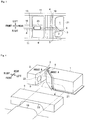
- the vehicle body structure according to the present embodiment is applied to a vehicle 10 shown in Fig. 1 .
- An engine, a transmission or the like are disposed in an engine room positioned frontward than a vehicle interior of the vehicle 10, and an exhaust pipe 8 is arranged below a floor in a front-rear direction.
- An arrangement position of the exhaust pipe 8 is below a backbone portion 16 longitudinally crossing a center of a main floor panel 15 (floor panel) in a vehicle width direction.
- the backbone portion 16 is a part of the main floor panel 15 bulging toward the vehicle interior in a tunnel shape.
- a front end portion of the exhaust pipe 8 is connected with the engine, and a rear end portion thereof is connected with a muffler 2 (a silencer, a muffler) disposed at a rear of the vehicle 10.
- a muffler 2 a silencer, a muffler
- a propeller shaft is disposed in parallel with the exhaust pipe 8 below the backbone portion 16, when the vehicle 10 is a four-wheel drive.
- a reduction catalyst, a post-stage catalyst or the like which purify nitrogen oxides (NOx) contained in exhaust of the engine are interposed in a path of the exhaust pipe 8.
- An injector which injects a reducing agent to be supplied to the exhaust is provided on an upstream side of the reduction catalyst.
- the reducing agent for example, an aqueous urea solution or an aqueous ammonia solution is used.
- An additive injected from the injector performs as the reducing agent which reduces the nitrogen oxides to nitrogen by the reduction catalyst.
- Such an exhaust purification system is widely used in automobiles, working machines, ships, power generation facilities, or the like equipped with a diesel engine or a lean burn engine.
- a tank 1 for storing the additive is disposed adjacent to the muffler 2 which is disposed at a rear of the vehicle 10 and is connected to the injector via a supply pipe 7.
- the main floor panel 15 is approximately a horizontal plane shape.
- a rear floor panel 17 forming a floor surface of a rear seat or a luggage compartment is disposed at a rear end portion of the main floor panel 15.
- the rear floor panel 17 forms a floor surface continuous with the main floor panel 15 at the rear of the main floor panel 15 in the vehicle 10.
- a dash panel 18 for partitioning the vehicle interior and the engine room is erected at a front end portion of the main floor panel 15.
- the rear floor panel 17 extends obliquely upward from a rear of the main floor panel 15 and then extends in a horizontal direction, so as to form a stair shape. Meanwhile, the dash panel 18 extends obliquely upward toward a front of the main floor panel 15.
- main floor panel 15, the dash panel 18, and the rear floor panel 17 may be formed separately, or may be formed integrally (for example, by bending a single plate).
- Fig. 2 shows an example in which the main floor panel 15, the dash panel 18, and the rear floor panel 17 are formed integrally.
- Side members 11, a front floor cross member 12, and a rear floor cross member 13 which perform as frame members of a vehicle body are attached to a lower surface side of the main floor panel 15, the rear floor panel 17, and the dash panel 18.
- the side members 11, the front floor cross member 12, and the rear floor cross member 13 form a closed cross section structure on a lower surface of the main floor panel 15, the rear floor panel 17, and the dash panel 18.
- the side members 11 are provided on the left and right with space in the vehicle width direction therebetween, and extend in the front-rear direction of the vehicle 10.
- the front floor cross member 12 and the rear floor cross member 13 are provided with space in the front-rear direction, and extend in the vehicle width direction.
- Arrangement positions of the side members 11 are separately set at positions slightly inward from a left side surface and a right side surface of the vehicle 10.
- An arrangement position of the front floor cross member 12 is set near a boundary between the main floor panel 15 and the dash panel 18, and an arrangement position of the rear floor cross member 13 is set near a boundary between the main floor panel 15 and the rear floor panel 17.
- the cross members 12, 13 are disposed, on the front end portion and the rear end portion of the main floor panel 15 respectively, at positions which are not positions where the dash panel 18 and the rear floor panel 17 rise (inclined parts).
- the backbone portion 16 is formed over the entire length from the front end portion to the rear end portion of the main floor panel 15 so as to connect with a rising portion of the dash panel 18 and a rising portion of the rear floor panel 17 in a horizontal direction.
- a fuel tank 9 for storing fuel of the engine mounted on the vehicle 10 is disposed below the rear floor panel 17 at the rear of the rear floor cross member 13.
- the side members 11 are arranged on the left and right of the fuel tank 9, and the rear floor cross member 13 and a rear suspension cross member 19 (a cross member for rear suspension) are arranged at a front and a rear of the fuel tank 9.
- the rear suspension cross member 19 is a frame member for supporting the rear suspension, and is disposed to be connected with the left and right side members 11 near rear wheels.
- a general shape of the fuel tank 9 is a horizontally long rectangular parallelepiped shape.
- the rear suspension cross member 19 according to the present embodiment is provided between the backbone portion 16 and the tank 1, and extends in the vehicle width direction.
- a ventilation portion 23 having a shape recessed toward the inside of the fuel tank 9 is formed on a bottom surface of the fuel tank 9.
- the ventilation portion 23 is a part bulging upward in a tunnel shape from the bottom surface of the fuel tank 9, and has substantially the same shape as the backbone portion 16 in a front view of the vehicle 10. Therefore, a flow of travel wind passing through the backbone portion 16 and the ventilation portion 23 and heading rearward is formed.
- the tank 1 is disposed adjacent to the muffler 2 in a vehicle width direction at the rear of the rear suspension cross member 19 and at a lower surface side of the rear floor panel 17.
- a clearance enough to allow the travel wind to pass through is provided between the tank 1 and the muffler 2.
- the clearance is referred to as "passage portion 3".
- a position of the passage portion 3 in the vehicle width direction is set at a position displaced from a position opposite to the backbone portion 16 in the vehicle width direction. That is, the positions of the tank 1 and the muffler 2 are shifted to either a right or left direction with respect to a center in the vehicle width direction so that the clearance between the tank 1 and the muffler 2 is not positioned at a direct rear of the backbone portion 16.
- the passage portion 3 is disposed at a position which is not included in a portion where the backbone portion 16 extends to the rear as it is, and is shifted to either the right or left from the portion where the backbone portion 16 extends to the rear as it is.
- the tank 1 is positioned at a left side of the muffler 2, and a displacement direction of the passage portion 3 is a right side (a lower side in Fig. 3 ) of the vehicle 10.
- a first notched portion 4 (notched portion) is formed on either one of the tank 1 and the muffler 2 which is positioned at a side opposite to the displacement direction of the passage portion 3.
- the first notched portion 4 is formed on the tank 1 positioned at a left side of the vehicle 10.
- the passage portion 3 is disposed at a position displaced from a muffler 2 side.
- the tank 1 is disposed at a position opposite to the backbone portion 16.
- the first notched portion 4 is a part provided so as to introduce a part of the travel wind passing through the backbone portion 16 to the passage portion 3.
- the first notched portion 4 has an expanded shape from the passage portion 3 toward a backbone portion 16 side.
- the shape of the first notched portion 4 can also be expressed as a tapered shape toward the rear of the vehicle 10.
- a heat shield 6 is disposed at an inner side of the first notched portion 4 so as to suppress transmission of exhaust heat to the tank 1.
- a lower surface side of the tank 1 is covered with a tank cover 21 in a planar shape so as to prevent deformation or chipping wear caused by stones flying from a road surface and contamination due to muddy water.
- the passage portion 3 is provided with the first notched portion 4 formed by cutting out a front side face of the tank 1, and a second notched portion 5 (notched portion) formed by cutting out a front side face of the muffler 2.
- the first notched portion 4 is formed in a planar shape in which a normal line extends toward a right front of the vehicle 10.
- the first notched portion 4 has the expanded shape from the passage portion 3 toward the backbone portion 16 side. That is, the first notched portion 4 has a shape extending to a position opposite to the backbone portion 16.
- the second notched portion 5 is formed in a planar shape in which a normal line extends toward a left front of the vehicle 10.
- the second notched portion 5 has an expanded shape from the passage portion 3 toward a front.
- the first notched portion 4 and the second notched portion 5 forms a shape in conformity with a V-shaped wedge shape.
- the heat shield 6 is disposed substantially in parallel with a surface of the first notched portion 4.
- a notch angle A of the first notched portion 4 is formed larger than a notch angle B of the second notched portion 5.
- the notch angles A, B are angles that represent an extent to which the first notched portion 4 and the second notched portion 5 are open with respect to a front-rear direction in a horizontal plane. That is, in the horizontal plane, a rotation angle required to make a center line of the vehicle 10 parallel to the surface of the first notched portion 4 is the notch angle A, and a rotation angle required to make the center line of the vehicle 10 parallel to the surface of the second notched portion 5 is the notch angle B. Since the notch angle A is set larger than the notch angle B, a surface area of a portion on the surface of the tank 1 to be cooled by the travel wind is larger, and cooling performance of the tank 1 and the additive is improved.
- An exhaust pipe connection port 22 which is a connecting location of the muffler 2 and the exhaust pipe 8 is disposed on the second notched portion 5. That is, the muffler 2 is connected to the exhaust pipe 8 in the second notched portion 5. Therefore, the connecting location of the muffler 2 and the exhaust pipe 8 where temperature tends to be high is efficiently cooled by the travel wind.
- the first notched portion 4 is provided on a tank 1 side, spacious connection space is created, and an assembling workability and a mounting property are improved.
- the connecting location of the muffler 2 and the exhaust pipe 8 may be provided at the passage portion 3 when sufficient connection space is secured. That is, the muffler 2 may be configured to connect with the exhaust pipe 8 in the passage portion 3.
- Dashed lines in Fig. 4 represent a shape obtained by projecting a cross-sectional shape of the backbone portion 16 after extending in a vehicle length direction on a front surface of the tank 1. Since the passage portion 3 is disposed at a position which is not a position at direct rear of the backbone portion 16, the travel wind passing through the backbone portion 16 is diffused in the vehicle width direction by contacting the front surface of the tank 1. Therefore, the travel wind passing through the backbone portion 16 does not flow into the passage portion 3 directly, and an excessive increase in the flow velocity is suppressed. Subsequently, a part of the diffused travel wind flows into a wedge-shaped space formed by the first notched portion 4 and the second notched portion 5, passes through the passage portion 3, and flows toward the rear of the vehicle 10. As described above, by providing the notched portions 4, 5, the decelerated travel wind is efficiently introduced into a passage portion 3 side, and a flow rate of the travel wind for cooling the tank 1 and the muffler 2 is secured.
- the passage portion 3 can be cooled by using a part of the travel wind, among the travel wind passing through the backbone portion 16, diffused in the vehicle width direction by contacting the front surfaces of the tank 1 and the muffler 2. Therefore, the travel wind passing through the backbone portion 16 can be prevented from concentrating on the passage portion 3. Accordingly, local supercooling of the passage portion 3 during traveling at high speed can be prevented, the cooling performance of the tank 1 and the muffler 2 can be improved, and an individual cooling state can be stabilized separately.
- the tank 1 is disposed at a position opposite to the backbone portion 16. Therefore, a dimension of the tank 1 in the vehicle width direction can be increased compared with the muffler 2, and the tank capacity can be increased. In addition, since almost all of the travel wind passing through the backbone portion 16 will contact the front surface of the tank 1, the cooling performance of the tank 1 can be improved.
- the rear suspension cross member 19 is disposed between the backbone portion 16 and the tank 1. Therefore, the tank 1 and the muffler 2 can be protected from stepping stones passing through the backbone portion 16 by the rear suspension cross member 19. Accordingly, chipping wear or deformation of the tank 1 and the muffler 2, and contamination due to muddy water are prevented.
- the first notched portion 4 is formed into a shape extending to the position opposite to the backbone portion 16. That is, in the front view of the vehicle 10, the first notched portion 4 is disposed at a position where the backbone portion 16 and the first notched portion 4 are overlapped with each other. Therefore, the travel wind can reliably flow into the passage portion 3, and the cooling performance of the tank 1 and the muffler 2 can be further improved.
- the connecting location between the muffler 2 and the exhaust pipe 8 where the temperature tends to be high can be efficiently cooled. Accordingly, the cooling performance of the muffler 2 can be further improved, and therefore the cooling performance of the tank 1 and the additive can be improved. Additionally, even in a case where the muffler 2 is connected with the exhaust pipe 8 in the passage portion 3, the same effect as that of the above-described vehicle body structure can be obtained, and the connecting location of the muffler 2 and the exhaust pipe 8 can be efficiently cooled.
- the notch angle A is set larger than the notch angle B, the surface area of the portion on the surface of the tank 1 to be cooled by the travel wind can be larger, and the cooling performance of the tank 1 and the additive can be improved. Since the dimension of the tank 1 in the vehicle width direction is larger than that of the muffler 2, the passage portion 3 can be brought closer to the backbone portion 16 by making the notch angle A larger. Alternatively, an overlapping area of the passage portion 3 and the backbone portion 16 can be increased in the front view of the vehicle 10.
- the flow of the travel wind introduced into the passage portion 3 can further promoted, and the cooling performance of the tank 1 and the muffler 2 can be improved.
- the ventilation portion 23 at the bottom surface of the fuel tank 9 disposed at a front of the muffler 2
- the introduction of the travel wind into the passage portion 3 can be further promoted. Therefore, the cooling performance of the tank 1 and the muffler 2 can be further improved.
- a type of additive is not limited to urea water.
- ammonia water may be used instead of the urea water.
- hydrocarbon HC, unburned fuel
- PM particulate matters
- Fig. 5A shows a case where the first notched portion 4 is formed on the tank 1, and the second notched portion 5 is not formed on the muffler 2.
- Fig. 5B shows a case where the first notched portion 4 is not formed on the tank 1, and the second notched portion 5 is formed on the muffler 2. In this manner, the first notched portion 4 and the second notched portion 5 may be appropriately omitted.
- the travel wind passing through the backbone portion 16 may be introduced into the passage portion 3 after being decelerated, and the same effect as that of the above-described embodiment may be obtained.
- the travel wind may be introduced into the passage portion 3 more smoothly, by forming the first notched portion 4 and the second notched portion 5 into a curved surface shape.
- the decelerated travel wind may be introduced into the passage portion 3 smoothly, and the same effect as that of the above-described embodiment may be obtained.
Landscapes
- Engineering & Computer Science (AREA)
- Chemical & Material Sciences (AREA)
- Combustion & Propulsion (AREA)
- Mechanical Engineering (AREA)
- General Engineering & Computer Science (AREA)
- Transportation (AREA)
- Body Structure For Vehicles (AREA)
- Cooling, Air Intake And Gas Exhaust, And Fuel Tank Arrangements In Propulsion Units (AREA)
Claims (6)
- Fahrzeugkarosseriestruktur, aufweisend:eine Hauptbodenplatte (15) mit einem Rückgratteil (16), das sich tunnelförmig zu einem Fahrzeuginnenraum wölbt;eine hintere Bodenplatte (17), die mit einem Fahrzeugheckteil der Hauptbodenplatte (15) einen kontinuierlichen Boden bildet;einen Tank (1), der unter der hinteren Bodenplatte (17) vorgesehen ist und ein dem Abgas zuzusetzendes Additiv aufnimmt; undeinen Schalldämpfer (2), der mit einem Auspuffrohr (8) verbunden und in einer Fahrzeugbreitenrichtung parallel zum Tank (1) angeordnet ist,wobei ein Durchgangsabschnitt (3) zwischen dem Tank (1) und dem Schalldämpfer (2) an einer Position angeordnet ist, die von einer dem Rückgratteil gegenüberliegenden Position in Bezug auf die Mitte in Fahrzeugbreitenrichtung nach links oder rechts versetzt ist, so dass der Durchgangsabschnitt (3) nicht unmittelbar hinter dem Rückgratteil (16) positioniert ist, undwobei eines der Bauteile Tank (1) und Schalldämpfer (2), das an einer einer Versatzrichtung des Durchgangsabschnitts (3) gegenüberliegenden Seite positioniert ist, einen eingekerbten Abschnitt (4) aufweist, der von dem Durchgangsabschnitt (3) zu einer Rückgratteilseite eine aufgeweitete Form aufweist.
- Fahrzeugkarosseriestruktur nach Anspruch 1,
wobei der Durchgangsabschnitt (3) an einer zur Schalldämpferseite versetzten Position angeordnet ist, und
wobei der Tank (1) an einer dem Rückgratteil (3) gegenüberliegenden Position angeordnet ist. - Fahrzeugkarosseriestruktur nach Anspruch 1 oder 2, ferner aufweisend:
einen Hinterachsen-Querträger (19), der zwischen dem Rückgratteil (16) und dem Tank (1) vorgesehen ist und sich in Fahrzeugbreitenrichtung erstreckt. - Fahrzeugkarosseriestruktur nach einem der Ansprüche 1 bis 3,
wobei sich der eingekerbte Abschnitt (4) zu einer dem Rückgratteil (16) gegenüberliegenden Position erstreckt. - Fahrzeugkarosseriestruktur nach einem der Ansprüche 1 bis 4,
wobei der Schalldämpfer (2) im eingekerbten Abschnitt (4) mit dem Auspuffrohr (8) verbunden ist. - Fahrzeugkarosseriestruktur nach einem der Ansprüche 1 bis 5,
wobei das jeweils andere der Bauteile Tank (1) und Schalldämpfer (2) einen weiteren eingekerbten Abschnitt (5) aufweist, der eine vom Durchgangsabschnitt (3) zur Rückgratteilseite hin aufgeweitete Form aufweist.
Applications Claiming Priority (1)
| Application Number | Priority Date | Filing Date | Title |
|---|---|---|---|
| JP2016246335A JP6708114B2 (ja) | 2016-12-20 | 2016-12-20 | 車体構造 |
Publications (2)
| Publication Number | Publication Date |
|---|---|
| EP3339074A1 EP3339074A1 (de) | 2018-06-27 |
| EP3339074B1 true EP3339074B1 (de) | 2020-03-04 |
Family
ID=60781775
Family Applications (1)
| Application Number | Title | Priority Date | Filing Date |
|---|---|---|---|
| EP17208776.9A Active EP3339074B1 (de) | 2016-12-20 | 2017-12-20 | Fahrzeugkarosseriestruktur |
Country Status (2)
| Country | Link |
|---|---|
| EP (1) | EP3339074B1 (de) |
| JP (1) | JP6708114B2 (de) |
Family Cites Families (6)
| Publication number | Priority date | Publication date | Assignee | Title |
|---|---|---|---|---|
| JPS4826612B1 (de) | 1968-10-09 | 1973-08-13 | ||
| JPS60175775U (ja) * | 1984-05-02 | 1985-11-21 | 日産自動車株式会社 | 自動車のパナ−ルロツド取付部構造 |
| DE102007019912A1 (de) * | 2007-04-27 | 2008-11-06 | Daimler Ag | Anordnung eines Bauteils an einer Unterseite eines Personenkraftwagens |
| JP5029270B2 (ja) * | 2007-10-03 | 2012-09-19 | マツダ株式会社 | 車両の下部車体構造 |
| JP4826612B2 (ja) * | 2007-10-12 | 2011-11-30 | マツダ株式会社 | 車両の排気浄化装置配設構造 |
| JP5126534B2 (ja) * | 2008-10-29 | 2013-01-23 | スズキ株式会社 | 車両の排気装置 |
-
2016
- 2016-12-20 JP JP2016246335A patent/JP6708114B2/ja active Active
-
2017
- 2017-12-20 EP EP17208776.9A patent/EP3339074B1/de active Active
Non-Patent Citations (1)
| Title |
|---|
| None * |
Also Published As
| Publication number | Publication date |
|---|---|
| JP2018099959A (ja) | 2018-06-28 |
| EP3339074A1 (de) | 2018-06-27 |
| BR102017027651A2 (pt) | 2018-10-30 |
| JP6708114B2 (ja) | 2020-06-10 |
Similar Documents
| Publication | Publication Date | Title |
|---|---|---|
| EP2048016B1 (de) | Struktur zur Anordnung einer Abgasreinigungsvorrichtung für ein Fahrzeug | |
| KR20250088788A (ko) | 작업 차량의 엔진 장치 | |
| KR102183434B1 (ko) | 트랙터 | |
| JP2017094885A (ja) | 車体構造 | |
| JP6772451B2 (ja) | 車体構造 | |
| EP3339074B1 (de) | Fahrzeugkarosseriestruktur | |
| JP2009078591A (ja) | 排気浄化装置の設置構造 | |
| CN111033014B (zh) | 车辆用发动机 | |
| JP7310308B2 (ja) | 車両の尿素水タンク | |
| EP3339073B1 (de) | Fahrzeugkarosseriestruktur | |
| JP7806926B2 (ja) | タンク | |
| US7926264B2 (en) | Vehicle exhaust system | |
| KR20140026829A (ko) | 콤바인의 배기가스 후처리장치 취부구조 | |
| EP3173275B1 (de) | Tankanordnungsstruktur | |
| JP6508269B2 (ja) | 車両用排気システム | |
| JP6662281B2 (ja) | 車体構造 | |
| JP7852782B1 (ja) | 水素エンジン車両 | |
| JP6805803B2 (ja) | 車体構造 | |
| BR102017027651B1 (pt) | Estrutura de carroceria de veículo | |
| JP2018064460A (ja) | コンバイン | |
| JP2017149226A (ja) | 車体構造 | |
| JP2018184896A (ja) | サプライモジュール |
Legal Events
| Date | Code | Title | Description |
|---|---|---|---|
| PUAI | Public reference made under article 153(3) epc to a published international application that has entered the european phase |
Free format text: ORIGINAL CODE: 0009012 |
|
| STAA | Information on the status of an ep patent application or granted ep patent |
Free format text: STATUS: REQUEST FOR EXAMINATION WAS MADE |
|
| 17P | Request for examination filed |
Effective date: 20180120 |
|
| AK | Designated contracting states |
Kind code of ref document: A1 Designated state(s): AL AT BE BG CH CY CZ DE DK EE ES FI FR GB GR HR HU IE IS IT LI LT LU LV MC MK MT NL NO PL PT RO RS SE SI SK SM TR |
|
| AX | Request for extension of the european patent |
Extension state: BA ME |
|
| RAP1 | Party data changed (applicant data changed or rights of an application transferred) |
Owner name: MITSUBISHI JIDOSHA ENGINEERING K.K. Owner name: MITSUBISHI JIDOSHA KOGYO KABUSHIKI KAISHA |
|
| GRAP | Despatch of communication of intention to grant a patent |
Free format text: ORIGINAL CODE: EPIDOSNIGR1 |
|
| STAA | Information on the status of an ep patent application or granted ep patent |
Free format text: STATUS: GRANT OF PATENT IS INTENDED |
|
| RIC1 | Information provided on ipc code assigned before grant |
Ipc: B60K 13/04 20060101AFI20190812BHEP |
|
| INTG | Intention to grant announced |
Effective date: 20190918 |
|
| GRAS | Grant fee paid |
Free format text: ORIGINAL CODE: EPIDOSNIGR3 |
|
| GRAA | (expected) grant |
Free format text: ORIGINAL CODE: 0009210 |
|
| STAA | Information on the status of an ep patent application or granted ep patent |
Free format text: STATUS: THE PATENT HAS BEEN GRANTED |
|
| RIN1 | Information on inventor provided before grant (corrected) |
Inventor name: SANO, TAKAYUKI Inventor name: YAMAMOTO, MASAHIRO Inventor name: INDEN, KAZUTO |
|
| AK | Designated contracting states |
Kind code of ref document: B1 Designated state(s): AL AT BE BG CH CY CZ DE DK EE ES FI FR GB GR HR HU IE IS IT LI LT LU LV MC MK MT NL NO PL PT RO RS SE SI SK SM TR |
|
| REG | Reference to a national code |
Ref country code: GB Ref legal event code: FG4D |
|
| REG | Reference to a national code |
Ref country code: CH Ref legal event code: EP |
|
| REG | Reference to a national code |
Ref country code: AT Ref legal event code: REF Ref document number: 1239972 Country of ref document: AT Kind code of ref document: T Effective date: 20200315 |
|
| REG | Reference to a national code |
Ref country code: DE Ref legal event code: R096 Ref document number: 602017012534 Country of ref document: DE |
|
| REG | Reference to a national code |
Ref country code: IE Ref legal event code: FG4D |
|
| PG25 | Lapsed in a contracting state [announced via postgrant information from national office to epo] |
Ref country code: FI Free format text: LAPSE BECAUSE OF FAILURE TO SUBMIT A TRANSLATION OF THE DESCRIPTION OR TO PAY THE FEE WITHIN THE PRESCRIBED TIME-LIMIT Effective date: 20200304 Ref country code: NO Free format text: LAPSE BECAUSE OF FAILURE TO SUBMIT A TRANSLATION OF THE DESCRIPTION OR TO PAY THE FEE WITHIN THE PRESCRIBED TIME-LIMIT Effective date: 20200604 Ref country code: RS Free format text: LAPSE BECAUSE OF FAILURE TO SUBMIT A TRANSLATION OF THE DESCRIPTION OR TO PAY THE FEE WITHIN THE PRESCRIBED TIME-LIMIT Effective date: 20200304 |
|
| REG | Reference to a national code |
Ref country code: NL Ref legal event code: MP Effective date: 20200304 |
|
| PG25 | Lapsed in a contracting state [announced via postgrant information from national office to epo] |
Ref country code: LV Free format text: LAPSE BECAUSE OF FAILURE TO SUBMIT A TRANSLATION OF THE DESCRIPTION OR TO PAY THE FEE WITHIN THE PRESCRIBED TIME-LIMIT Effective date: 20200304 Ref country code: SE Free format text: LAPSE BECAUSE OF FAILURE TO SUBMIT A TRANSLATION OF THE DESCRIPTION OR TO PAY THE FEE WITHIN THE PRESCRIBED TIME-LIMIT Effective date: 20200304 Ref country code: HR Free format text: LAPSE BECAUSE OF FAILURE TO SUBMIT A TRANSLATION OF THE DESCRIPTION OR TO PAY THE FEE WITHIN THE PRESCRIBED TIME-LIMIT Effective date: 20200304 Ref country code: BG Free format text: LAPSE BECAUSE OF FAILURE TO SUBMIT A TRANSLATION OF THE DESCRIPTION OR TO PAY THE FEE WITHIN THE PRESCRIBED TIME-LIMIT Effective date: 20200604 Ref country code: GR Free format text: LAPSE BECAUSE OF FAILURE TO SUBMIT A TRANSLATION OF THE DESCRIPTION OR TO PAY THE FEE WITHIN THE PRESCRIBED TIME-LIMIT Effective date: 20200605 |
|
| REG | Reference to a national code |
Ref country code: LT Ref legal event code: MG4D |
|
| PG25 | Lapsed in a contracting state [announced via postgrant information from national office to epo] |
Ref country code: NL Free format text: LAPSE BECAUSE OF FAILURE TO SUBMIT A TRANSLATION OF THE DESCRIPTION OR TO PAY THE FEE WITHIN THE PRESCRIBED TIME-LIMIT Effective date: 20200304 |
|
| PG25 | Lapsed in a contracting state [announced via postgrant information from national office to epo] |
Ref country code: IS Free format text: LAPSE BECAUSE OF FAILURE TO SUBMIT A TRANSLATION OF THE DESCRIPTION OR TO PAY THE FEE WITHIN THE PRESCRIBED TIME-LIMIT Effective date: 20200704 Ref country code: CZ Free format text: LAPSE BECAUSE OF FAILURE TO SUBMIT A TRANSLATION OF THE DESCRIPTION OR TO PAY THE FEE WITHIN THE PRESCRIBED TIME-LIMIT Effective date: 20200304 Ref country code: ES Free format text: LAPSE BECAUSE OF FAILURE TO SUBMIT A TRANSLATION OF THE DESCRIPTION OR TO PAY THE FEE WITHIN THE PRESCRIBED TIME-LIMIT Effective date: 20200304 Ref country code: PT Free format text: LAPSE BECAUSE OF FAILURE TO SUBMIT A TRANSLATION OF THE DESCRIPTION OR TO PAY THE FEE WITHIN THE PRESCRIBED TIME-LIMIT Effective date: 20200729 Ref country code: SM Free format text: LAPSE BECAUSE OF FAILURE TO SUBMIT A TRANSLATION OF THE DESCRIPTION OR TO PAY THE FEE WITHIN THE PRESCRIBED TIME-LIMIT Effective date: 20200304 Ref country code: EE Free format text: LAPSE BECAUSE OF FAILURE TO SUBMIT A TRANSLATION OF THE DESCRIPTION OR TO PAY THE FEE WITHIN THE PRESCRIBED TIME-LIMIT Effective date: 20200304 Ref country code: RO Free format text: LAPSE BECAUSE OF FAILURE TO SUBMIT A TRANSLATION OF THE DESCRIPTION OR TO PAY THE FEE WITHIN THE PRESCRIBED TIME-LIMIT Effective date: 20200304 Ref country code: LT Free format text: LAPSE BECAUSE OF FAILURE TO SUBMIT A TRANSLATION OF THE DESCRIPTION OR TO PAY THE FEE WITHIN THE PRESCRIBED TIME-LIMIT Effective date: 20200304 Ref country code: SK Free format text: LAPSE BECAUSE OF FAILURE TO SUBMIT A TRANSLATION OF THE DESCRIPTION OR TO PAY THE FEE WITHIN THE PRESCRIBED TIME-LIMIT Effective date: 20200304 |
|
| REG | Reference to a national code |
Ref country code: AT Ref legal event code: MK05 Ref document number: 1239972 Country of ref document: AT Kind code of ref document: T Effective date: 20200304 |
|
| REG | Reference to a national code |
Ref country code: DE Ref legal event code: R097 Ref document number: 602017012534 Country of ref document: DE |
|
| PLBE | No opposition filed within time limit |
Free format text: ORIGINAL CODE: 0009261 |
|
| STAA | Information on the status of an ep patent application or granted ep patent |
Free format text: STATUS: NO OPPOSITION FILED WITHIN TIME LIMIT |
|
| PG25 | Lapsed in a contracting state [announced via postgrant information from national office to epo] |
Ref country code: IT Free format text: LAPSE BECAUSE OF FAILURE TO SUBMIT A TRANSLATION OF THE DESCRIPTION OR TO PAY THE FEE WITHIN THE PRESCRIBED TIME-LIMIT Effective date: 20200304 Ref country code: AT Free format text: LAPSE BECAUSE OF FAILURE TO SUBMIT A TRANSLATION OF THE DESCRIPTION OR TO PAY THE FEE WITHIN THE PRESCRIBED TIME-LIMIT Effective date: 20200304 Ref country code: DK Free format text: LAPSE BECAUSE OF FAILURE TO SUBMIT A TRANSLATION OF THE DESCRIPTION OR TO PAY THE FEE WITHIN THE PRESCRIBED TIME-LIMIT Effective date: 20200304 |
|
| 26N | No opposition filed |
Effective date: 20201207 |
|
| PG25 | Lapsed in a contracting state [announced via postgrant information from national office to epo] |
Ref country code: PL Free format text: LAPSE BECAUSE OF FAILURE TO SUBMIT A TRANSLATION OF THE DESCRIPTION OR TO PAY THE FEE WITHIN THE PRESCRIBED TIME-LIMIT Effective date: 20200304 Ref country code: SI Free format text: LAPSE BECAUSE OF FAILURE TO SUBMIT A TRANSLATION OF THE DESCRIPTION OR TO PAY THE FEE WITHIN THE PRESCRIBED TIME-LIMIT Effective date: 20200304 |
|
| REG | Reference to a national code |
Ref country code: CH Ref legal event code: PL |
|
| PG25 | Lapsed in a contracting state [announced via postgrant information from national office to epo] |
Ref country code: MC Free format text: LAPSE BECAUSE OF FAILURE TO SUBMIT A TRANSLATION OF THE DESCRIPTION OR TO PAY THE FEE WITHIN THE PRESCRIBED TIME-LIMIT Effective date: 20200304 |
|
| REG | Reference to a national code |
Ref country code: BE Ref legal event code: MM Effective date: 20201231 |
|
| PG25 | Lapsed in a contracting state [announced via postgrant information from national office to epo] |
Ref country code: LU Free format text: LAPSE BECAUSE OF NON-PAYMENT OF DUE FEES Effective date: 20201220 Ref country code: IE Free format text: LAPSE BECAUSE OF NON-PAYMENT OF DUE FEES Effective date: 20201220 |
|
| PG25 | Lapsed in a contracting state [announced via postgrant information from national office to epo] |
Ref country code: LI Free format text: LAPSE BECAUSE OF NON-PAYMENT OF DUE FEES Effective date: 20201231 Ref country code: CH Free format text: LAPSE BECAUSE OF NON-PAYMENT OF DUE FEES Effective date: 20201231 |
|
| PG25 | Lapsed in a contracting state [announced via postgrant information from national office to epo] |
Ref country code: TR Free format text: LAPSE BECAUSE OF FAILURE TO SUBMIT A TRANSLATION OF THE DESCRIPTION OR TO PAY THE FEE WITHIN THE PRESCRIBED TIME-LIMIT Effective date: 20200304 Ref country code: MT Free format text: LAPSE BECAUSE OF FAILURE TO SUBMIT A TRANSLATION OF THE DESCRIPTION OR TO PAY THE FEE WITHIN THE PRESCRIBED TIME-LIMIT Effective date: 20200304 Ref country code: CY Free format text: LAPSE BECAUSE OF FAILURE TO SUBMIT A TRANSLATION OF THE DESCRIPTION OR TO PAY THE FEE WITHIN THE PRESCRIBED TIME-LIMIT Effective date: 20200304 |
|
| PG25 | Lapsed in a contracting state [announced via postgrant information from national office to epo] |
Ref country code: MK Free format text: LAPSE BECAUSE OF FAILURE TO SUBMIT A TRANSLATION OF THE DESCRIPTION OR TO PAY THE FEE WITHIN THE PRESCRIBED TIME-LIMIT Effective date: 20200304 Ref country code: AL Free format text: LAPSE BECAUSE OF FAILURE TO SUBMIT A TRANSLATION OF THE DESCRIPTION OR TO PAY THE FEE WITHIN THE PRESCRIBED TIME-LIMIT Effective date: 20200304 |
|
| PG25 | Lapsed in a contracting state [announced via postgrant information from national office to epo] |
Ref country code: BE Free format text: LAPSE BECAUSE OF NON-PAYMENT OF DUE FEES Effective date: 20201231 |
|
| GBPC | Gb: european patent ceased through non-payment of renewal fee |
Effective date: 20211220 |
|
| PG25 | Lapsed in a contracting state [announced via postgrant information from national office to epo] |
Ref country code: GB Free format text: LAPSE BECAUSE OF NON-PAYMENT OF DUE FEES Effective date: 20211220 |
|
| PGFP | Annual fee paid to national office [announced via postgrant information from national office to epo] |
Ref country code: DE Payment date: 20251028 Year of fee payment: 9 |
|
| PGFP | Annual fee paid to national office [announced via postgrant information from national office to epo] |
Ref country code: FR Payment date: 20251110 Year of fee payment: 9 |