EP3339206B1 - Récipient à usage unique inviolable destiné à contenir des doses unitaires - Google Patents
Récipient à usage unique inviolable destiné à contenir des doses unitaires Download PDFInfo
- Publication number
- EP3339206B1 EP3339206B1 EP16306737.4A EP16306737A EP3339206B1 EP 3339206 B1 EP3339206 B1 EP 3339206B1 EP 16306737 A EP16306737 A EP 16306737A EP 3339206 B1 EP3339206 B1 EP 3339206B1
- Authority
- EP
- European Patent Office
- Prior art keywords
- container
- container body
- tamper
- head section
- connecting region
- Prior art date
- Legal status (The legal status is an assumption and is not a legal conclusion. Google has not performed a legal analysis and makes no representation as to the accuracy of the status listed.)
- Active
Links
Images



Classifications
-
- B—PERFORMING OPERATIONS; TRANSPORTING
- B65—CONVEYING; PACKING; STORING; HANDLING THIN OR FILAMENTARY MATERIAL
- B65D—CONTAINERS FOR STORAGE OR TRANSPORT OF ARTICLES OR MATERIALS, e.g. BAGS, BARRELS, BOTTLES, BOXES, CANS, CARTONS, CRATES, DRUMS, JARS, TANKS, HOPPERS, FORWARDING CONTAINERS; ACCESSORIES, CLOSURES, OR FITTINGS THEREFOR; PACKAGING ELEMENTS; PACKAGES
- B65D1/00—Rigid or semi-rigid containers having bodies formed in one piece, e.g. by casting metallic material, by moulding plastics, by blowing vitreous material, by throwing ceramic material, by moulding pulped fibrous material or by deep-drawing operations performed on sheet material
- B65D1/02—Bottles or similar containers with necks or like restricted apertures, designed for pouring contents
- B65D1/0223—Bottles or similar containers with necks or like restricted apertures, designed for pouring contents characterised by shape
- B65D1/023—Neck construction
- B65D1/0238—Integral frangible closures
-
- B—PERFORMING OPERATIONS; TRANSPORTING
- B65—CONVEYING; PACKING; STORING; HANDLING THIN OR FILAMENTARY MATERIAL
- B65D—CONTAINERS FOR STORAGE OR TRANSPORT OF ARTICLES OR MATERIALS, e.g. BAGS, BARRELS, BOTTLES, BOXES, CANS, CARTONS, CRATES, DRUMS, JARS, TANKS, HOPPERS, FORWARDING CONTAINERS; ACCESSORIES, CLOSURES, OR FITTINGS THEREFOR; PACKAGING ELEMENTS; PACKAGES
- B65D81/00—Containers, packaging elements, or packages, for contents presenting particular transport or storage problems, or adapted to be used for non-packaging purposes after removal of contents
- B65D81/24—Adaptations for preventing deterioration or decay of contents; Applications to the container or packaging material of food preservatives, fungicides, pesticides or animal repellants
- B65D81/26—Adaptations for preventing deterioration or decay of contents; Applications to the container or packaging material of food preservatives, fungicides, pesticides or animal repellants with provision for draining away, or absorbing, or removing by ventilation, fluids, e.g. exuded by contents; Applications of corrosion inhibitors or desiccators
- B65D81/266—Adaptations for preventing deterioration or decay of contents; Applications to the container or packaging material of food preservatives, fungicides, pesticides or animal repellants with provision for draining away, or absorbing, or removing by ventilation, fluids, e.g. exuded by contents; Applications of corrosion inhibitors or desiccators for absorbing gases, e.g. oxygen absorbers or desiccants
-
- B—PERFORMING OPERATIONS; TRANSPORTING
- B65—CONVEYING; PACKING; STORING; HANDLING THIN OR FILAMENTARY MATERIAL
- B65D—CONTAINERS FOR STORAGE OR TRANSPORT OF ARTICLES OR MATERIALS, e.g. BAGS, BARRELS, BOTTLES, BOXES, CANS, CARTONS, CRATES, DRUMS, JARS, TANKS, HOPPERS, FORWARDING CONTAINERS; ACCESSORIES, CLOSURES, OR FITTINGS THEREFOR; PACKAGING ELEMENTS; PACKAGES
- B65D81/00—Containers, packaging elements, or packages, for contents presenting particular transport or storage problems, or adapted to be used for non-packaging purposes after removal of contents
- B65D81/24—Adaptations for preventing deterioration or decay of contents; Applications to the container or packaging material of food preservatives, fungicides, pesticides or animal repellants
- B65D81/26—Adaptations for preventing deterioration or decay of contents; Applications to the container or packaging material of food preservatives, fungicides, pesticides or animal repellants with provision for draining away, or absorbing, or removing by ventilation, fluids, e.g. exuded by contents; Applications of corrosion inhibitors or desiccators
- B65D81/266—Adaptations for preventing deterioration or decay of contents; Applications to the container or packaging material of food preservatives, fungicides, pesticides or animal repellants with provision for draining away, or absorbing, or removing by ventilation, fluids, e.g. exuded by contents; Applications of corrosion inhibitors or desiccators for absorbing gases, e.g. oxygen absorbers or desiccants
- B65D81/268—Adaptations for preventing deterioration or decay of contents; Applications to the container or packaging material of food preservatives, fungicides, pesticides or animal repellants with provision for draining away, or absorbing, or removing by ventilation, fluids, e.g. exuded by contents; Applications of corrosion inhibitors or desiccators for absorbing gases, e.g. oxygen absorbers or desiccants the absorber being enclosed in a small pack, e.g. bag, included in the package
-
- B—PERFORMING OPERATIONS; TRANSPORTING
- B65—CONVEYING; PACKING; STORING; HANDLING THIN OR FILAMENTARY MATERIAL
- B65D—CONTAINERS FOR STORAGE OR TRANSPORT OF ARTICLES OR MATERIALS, e.g. BAGS, BARRELS, BOTTLES, BOXES, CANS, CARTONS, CRATES, DRUMS, JARS, TANKS, HOPPERS, FORWARDING CONTAINERS; ACCESSORIES, CLOSURES, OR FITTINGS THEREFOR; PACKAGING ELEMENTS; PACKAGES
- B65D83/00—Containers or packages with special means for dispensing contents
- B65D83/04—Containers or packages with special means for dispensing contents for dispensing annular, disc-shaped, spherical or like small articles, e.g. tablets or pills
Definitions
- the invention relates to a tamper-evident single-use container for holding unitary dose products and its use.
- Single-use containers for pharmaceutical products are especially known from single-dose containers for holding a vaccine.
- Vaccine or other types of serum are often stored in single-use containers made of glass which are provided with a breakable head.
- FR 2 639 026 A1 and EP 0 076 418 A2 disclose plastic containers with a breakable head which can be removed before first use.
- Such containers are not useful for holding unitary dose products like loose pills or capsules, lozenges or granules.
- unitary dose products are usually packaged in tubular containers which are closed with a conventional openable cover.
- prior art containers are not tamper-evident because the cover can be repeatedly opened and closed.
- EP 0 076 418 A2 discloses a tamper-evident single-use container with the precharacterizing features of claim 1 which represents the closest prior art.
- An inventive tamper-evident single-use container for holding unitary dose products, especially solid pharmaceutical products comprises a container body made of plastic material with a bottom end and a tubular top end and a head section closing the top end, wherein the head section is integrally connected to the container body at a connecting region.
- the thickness of the plastic material at the connecting region is reduced by at least 50% as compared to the wall thickness of the container body.
- Such container made of plastic material is advantageous over single-use containers made of glass in that, when removing the head section from the container body and the material of the connecting region is broken, no sharp-edged chips will be generated. Further, the inventive container is handled in a straightforward way in that it is the perceived top end of the container which is removed. The container is inviolable apart from the connecting region integrally connecting the head section to the container body. Once the head section has been removed, the container can no longer be closed again so that any tampering with the container will immediately become evident.
- the head section is provided with protrusions and/or depressions which promote a firm grip. This feature helps the user to apply the required force to break the container.
- the protrusions and/or depressions can be molded as a part of the head section or can be provided using a further separate part which can be manufactured by bi-injection molding, overmolding or which can be molded in a separate manufacturing step before it is mounted to the container.
- the container and its head section are molded using a sliding splitmould in order to demould the container.
- the separate part can be customized depending on the user or the specific product intended to be contained. To this end, the separate part can be individualized as regards the shape, color, material or texture just to mention some examples.
- the body of the container is of a cylindrical shape with a round, oval or polygonal base.
- the plastic material according to the invention is preferably made of a suitable plastic material which is preferably selected from the group comprising radical or linear high and low density polyethylenes, copolymers of ethylene such as for example ethylene vinyl acetates, ethylene ethyl acrylates, ethylene butyl acrylates, ethylene maleic anhydrides, ethylene alpha olefines, regard-less of the methods of polymerisation or modification by grafting, homo polypropylene and copolymers, polybutene-1, polyisobutylene.
- Polyolefines are preferably selected to make the single-use container for cost reasons and because they are easy to use.
- polymer materials can be considered however such as polyvinyl chloride, copolymers of vinyl chloride, polyvinylidene chlorides, polystyrenes, copolymers of styrene, derivatives of cellulose, polyamides, polycarbonates, polyoxymethylenes, polyethylene terephthalates, polybutylene terephthalates, copolyesters, polyphenylene oxides, polymethyl methacrylates, copolymers of acrylate, fluoride polymers, polyphenylene sulphides, polyarylsulphones, polyaryletherketones, polyetherimides, polyimides, polyurethanes, phenol resins, melamine resins, urea resins, epoxy resins and unsaturated polyester resins.
- polyvinyl chloride copolymers of vinyl chloride, polyvinylidene chlorides, polystyrenes, copolymers of styrene, derivatives of cellulose, polyamides, polycarbonates, poly
- Biodegradable polymer materials with for example a starch base, are also possible such as polylactic acids (PLA).
- PLA polylactic acids
- the polymer used to produce the single-use container can also contain one or more additives such as fibers, expanding agents, additives such as stabilizers and colorants, sliding agents, demolding agents, adhesion agents or reinforced catching agents and/or any others according to the requirements of usage.
- additives such as fibers, expanding agents, additives such as stabilizers and colorants, sliding agents, demolding agents, adhesion agents or reinforced catching agents and/or any others according to the requirements of usage.
- the single-use container can also be made from injectable materials made in such a way that they are capable of absorbing various different pollutants such as humidity, oxygen, odour and other possible pollutants.
- the thermoplastic materials are thus themselves formulated with active agents belonging to a group of humidity absorbers, oxygen scavengers, odour absorbers and/or emitters of humidity or volatile olfactory organic compounds.
- Suitable dehydrating agents are selected from a group comprising silica gels, dehydrating clays, activated alumina, calcium oxide, barium oxide, natural or synthetic zeolites, molecular or similar sieves, or deliquescent salts such as magnesium sulfide, calcium chloride, aluminum chloride, lithium chloride, calcium bromide, zink chloride or the like.
- the dehydrating agent is a molecular sieve and/or a silica gel.
- a suitable oxygen collecting agent is selected from a group comprising metal powders having a reducing capacity, in particular iron, zinc, tin powders, metal oxides still having the ability to oxidize, in particular ferrous oxide, as well as compounds of iron such as carbides, carbonyls, hydroxides, used alone or in the presence of an activator such as hydroxides, carbonates, sulfites, thiosulfates, phosphates, organic acid salts, or hydrogen salts of alkaline metals or alkaline earth metals, activated carbon, activated alumina or activated clays.
- metal powders having a reducing capacity in particular iron, zinc, tin powders, metal oxides still having the ability to oxidize, in particular ferrous oxide, as well as compounds of iron such as carbides, carbonyls, hydroxides, used alone or in the presence of an activator such as hydroxides, carbonates, sulfites, thiosulfates, phosphates, organic acid salts, or
- agents for collecting oxygen can also be chosen from specific reactive polymers such as those described for example in the patents US 5,736,616 , WO 99/48963 and WO 98/051758 . These specific reactive polymers can be mixed with a thermoplastic polymer used to produce the single-use container according to the present invention.
- the amount of treatment agent introduced into the thermoplastic polymer to produce the single-use container according to the present invention expressed in percentage by weight can advantageously vary from 5% to 70%, preferably from 5% to 55% of the thermoplastic material used to produce the single-use container.
- the container By reducing the thickness of the plastic material at the connecting region by at least 50% as compared to the wall thickness of the container body, the container will be opened at a well-defined position.
- the plastic material of the container can comprise a plastic polymer composition including an active substance, the active substance preferably being a desiccant.
- the active substance can be a desiccant or can be different from a desiccant. It can be any substance or mixture of substances which trap and/or release certain compounds. It is possible, just to give some examples, to hold the unitary dose products inside the container free of oxygen or free of volatile organic compounds such as for example formaldehydes or other aldehydes.
- the head section has a round outer shape, preferably generally spherical outer shape. This makes the head section easy to grip by a user when a certain force will have to be applied in order to break the frangible connecting region between the head section and the container body.
- the tamper-evident single-use container further comprises a gorge on the head section.
- a gorge provides some protection of the thin-walled connecting region against an inadvertent mechanical impact.
- a gorge has the advantage that the circumferential length of the connecting region is reduced.
- the overall area of the connecting region i.e. the product of the wall thickness and the length of the connecting region, is decisive.
- a gorge reduces the circumferential length of the connecting region and facilitates the breaking of the connecting region or, when this is not required, makes it possible to increase the wall thickness as compared to a container without a gorge on the head section in the region between the container body and the head section.
- the angle A between the wall section of the container body and the wall section of the head section at the connecting region is at least 10°.
- the angle A corresponds to the maximum possible tilting of the head section around an axis perpendicular to the longitudinal axis of the container relative to the container body before the head section contacts the container body and prevents a further relative tilting motion of the head section.
- Such minimum angle of at least 10° is sufficient to tilt the head section to a sufficient degree so that the container will break at the connecting region.
- the connecting region bridges a distance between the container body and the head section, the length 1 of the connecting region in the direction of the distance being defined by 0mm ⁇ l ⁇ 1mm, more preferably 0mm ⁇ l ⁇ 0,5mm.
- the connecting region is preferably arranged and dimensioned such that the connecting region can be broken by tilting the head section relative to the container body around an axis which is perpendicular to the longitudinal axis of the container. Examples in the prior art in which the connecting region can be broken by a relative rotation around the longitudinal axis of the tubular container body between the head section and the tubular container body requires a high force so that the wall thickness of the connecting region has to be made very small. This, however, makes the connecting region vulnerable against any inadvertent impacts.
- the maximum outer dimensions of the head section are such that the head section does not protrude beyond the outer extension of the tubular container body.
- the maximum outer dimensions of the head section is preferably smaller than the outer diameter of the tubular container body.
- the maximum outer dimensions of the head section are larger than the inner diameter of the tubular container body. In this manner, the head section, once it has been broken, cannot be used to reclose the container body.
- the head section is shaped so that the head section, once removed from the container body, cannot be turned upside down and used to reclose the container body.
- This can be achieved e.g. by providing the upper part of the head section which is aligned with the fictitious extension of the inner wall surface of the cylindrical container body with a shape which cannot be inserted into the container body and become engaged therein.
- the tangent to that upper part of the head section which is aligned with the fictitious extension of the inner wall surface of the cylindrical container body should form an angle B to the longitudinal axis of the container body which exceeds 30°, preferably 45°.
- the cylindrical container body has an inner diameter d in and an outer diameter d out , and wherein a maximum outer outer diameter d head of the head section is selected to satisfy the equation d in ⁇ d head ⁇ d out .
- the wall thickness of the container body at the tubular top end thereof is at least 0.5mm, more preferred 0,8mm. This makes the plastic material of the container body sufficiently rigid in the region of the tubular top end such that the head can be easily broken while the container body maintains its basic shape without deforming or bending during breakage.
- the thickness of the plastic material at the connecting region is less than 0.5mm, preferably between 0.1mm and 0.5mm and more preferably between 0.1mm and 0.3mm. As outlined above, it is not the thickness alone of the plastic material of the connecting region, but also the length of the connecting region which determines the resistance of the single-use container against breaking at the contact region.
- single-use containers are usually of relatively small dimensions especially when storing pharmaceutical products. Therefore, on the basis of common sizes for such single-use containers for pharmaceutical substances, the above-mentioned range of the thickness of the plastic material was found to provide a sufficient stability to the container and, at the same time, to make it possible for an average adult to open the container by breaking the connecting region.
- the length of the connecting region is 0mm ⁇ l ⁇ 0.3mm.
- the container body is provided with an interior annular shoulder close to its bottom end.
- an annular shoulder close to the bottom end provides a stop for receiving and positioning a cover for closing the container at its bottom end, especially if the cover is integrated in the container body without protruding beyond the bottom end.
- the bottom end of the container is closed by (heat) welding together the lower end of the container body.
- This is an easy-to-perform process step for closing the container once the unitary dose products to be stored inside the container have been inserted into the container. Further, no extra part for closing the container is required.
- the wall thickness at the open end of the container body shall not exceed preferably 0,5mm, most preferably 0,3mm.
- the thickness of the container wall is not constant: the open end of the container wall has preferably a wall thickness of 0,5mm or less to allow for the welding operation, whereas the top end of the container has a wall thickness of 0,5mm or more to be sufficiently rigid to allow for breaking the connecting region.
- the tamper-evident single-use container comprises a cover closing the bottom end of the container body.
- the provision of a cover is the easiest option for closing the single-use container after the product to be stored therein has been inserted.
- the cover is received in the bottom end of the container body such that it does not protrude beyond the bottom end in a longitudinal direction of the container body. In this manner, the cover cannot be easily removed and the container cannot be openend unless the user breaks the connecting region to the head section.
- the container can be filled by placing it on a conveying surface, upside down. After filling, a cover is assembled by e.g. placing the cover above the container opening and pressing the cover onto the container body.
- the cover is provided with a recess which, in the assembled state, faces toward the outside of the container.
- This recess is used to grip the cover in the process of placing the cover above the container opening and pushing the cover when closing the container.
- the cover has a flat surface facing, in the assembled state, the outside of the container.
- the assembly of such cover can use a vacuum holder.
- the container and the cover can be provided with interlocking form-fit elements like a circumferential groove on the container body and a corresponding shaped and arranged circumferential rib on the cover.
- the form-fit connection of the rib and the groove additionally provides a sealing contact between the container body and the cover.
- the position of the rib and the groove can be exchanged.
- a further advantage of the form-fit connection is the high resistance of the cover against being removed again from the container body. This increases the safety that the container cannot be opened and tampered with by unauthorized persons.
- the cover can be provided with a flexible skirt or a deformable lip around its circumference which further improves the sealing relationship between the cover and the container body because the skirt compensates because of its flexibility manufacturing tolerances as well as unevenness of either the cover or the container body.
- the cover is attached to the container body by welding, crimping or a force fit, more preferably by welding or crimping.
- the cover is adapted to close the bottom end of the container.
- the production and the delivery of the basic structure of the container and the provision and delivery of the cover can be carried out separately because the cover will only be attached to the bottom end of the container once the unitary dose product will have been introduced into the interior of the container.
- the cover might comprise gas treating agent.
- the cover comprises a chamber filled with a gas treating agent or holds a tablet, a canister, a packet filled with a gas treating agent, preferably a gas releasing agent or gas adsorbing agent.
- the gas treating agent is entrained within the resin forming the cover.
- the gas treating agent is an oxygen scavenger so that, once the single-use container has been closed by means of the cover, the inner atmosphere of the container can be brought to and maintained at a reduced oxygen level.
- the gas treating agent is a desiccant so that, once the single-use container has been closed by means of the cover, the inner atmosphere of the container can be brought to and maintained at a controlled humidity level.
- the gas treating agent can be any substance or mixture of substances which trap and/or release component from/into the container headspace.
- the tamper-evident feature and the possibility to tailor the inner atmosphere of the container has a specific use for storing a pharmaceutical solid substance, preferably loose pills, pellets, globules, granules, powder or capsules.
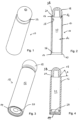
- Fig. 1 shows a single-use container 10 in a three dimensional view.
- Fig. 2 is the corresponding cross-sectional view.
- the container 10 consists of a tubular container body 12 with a bottom end or open end 14 and a top end 16.
- a head section 18 is integrally formed with the container body 12 at the top end 16 of the container body.
- the thickness d 2 of the material at the connecting region is between 0.1mm and 0.5mm and preferably between 0.1mm and 0.25mm.
- the connecting region 20, which is the frangible region of the inventive container is on the inner side of the wall of the container. In other words, it starts from the inner side 28 of the wall forming the container body 12 which faces the interior 30 of the container. This serves the purpose that, when the connecting region is broken, the broken section faces towards the inside of the container so that a user grasping the opened container does not contact possible sharp edges of the broken connecting region. Further, such broken container is suitable for direct oral supply of the medication contained therein.
- the container body is provided close to its bottom end 14 with a shoulder 26 which, as can be seen in Figs. 3 and 4 , serves to receive a cover 24 in order to close the container after the unitary dose product or products to be filled into the container have been introduced into the interior 30 of the container.
- the cover 24 is fixed to the container body 12 by means of a press fit. As can be seen from Figs. 3 and 4 , the cover 24 does not protrude beyond the bottom end 14 of the container body.
- the head section 18 of the container has a spherical shape forming an annular protrusion 38 to promote a firm grip of the head section 18 by a user.
- an angle A is formed between the wall sections of the container body and the head section adjacent to the connecting region 20. This angle is at least 10°.
- the container body 12, the head section 18 as well as the connecting region 20 are made of plastic material, here in a single piece. The same preferably applies to the cover 24.
- the cover 24 can hold a gas treating agent.
- the gas treating agent could be embedded into the composition of the cover and/or container body 12. Further, the gas treating agent could be provided by means of a canister or by means of an active tablet which can for example be made of compressed desiccant or desiccant entrained polymer.
- Such canister 32 is schematically shown in Fig. 5 .
- the cover 24 is provided with a ring-shaped holding structure 34 which, when the cover 24 is press fit in the container body 12, firmly holds the canister 32.
- the cover comprises a gas treating agent.
- the cover comprises a chamber filled with a gas treating agent or holding a tablet, a canister, a packet filled with a gas treating agent, preferably a gas releasing agent or gas adsorbing agent.
- the gas treating agent is entrained within the resin forming the cover.
- the container 10 as shown in Fig. 5 differs from that as shown in Fig. 4 by the additional provision of a head section 18 which has a further part 36 that can be bi-injected, overmolded or simply attached onto the head section 18 in order to provide another part of a different color or a different material.
- Different colors can e.g. be used to distinguish different products contained in the container, like different homeopathic products or different medication dosing or strength.
- a further advantage is that a container with a simple shape can be used before it is later on customized by the further part 36. Such a simple shape of the container can be naturally demoulded.
- the container as shown in Fig. 6 has a head section 18 with a different shape. Unlike the head section as shown in the embodiments of Figs. 1 to 5 , the head section according to Fig. 6 does not have a spherical shape. It is provided with protrusions 38 which enable a user to firmly grip the head section of the container before breaking the connecting region 20 in the process of opening the container.
- the bottom end 14 of the container body 12 is provided with a shoulder 26.
- the container body 12 can also have the same thickness over its interior length without forming a shoulder close to the bottom end 14.
- Figs. 7 to 10 corresponds to that as shown and explained above with reference to Figs. 1 to 4 .
- the cover 24 is secured to the bottom end 14 of the container body by "crimping".
- the term "crimping" is supposed to describe that the cover 24 is inserted into the lower part of the container body and resting against the shoulder 26. After this, it is secured to the container body 12 by applying heat and pressure on the bottom end 14 of the container body 12 so that the bottom end 14 is bent towards the interior of the container body 12 and generates a form fit which prevents the remove of the cover 24 from the container 10.
- the section 40 of the container body close to its bottom end 14 it is preferably made longer in the longitudinal direction of the container as compared to the corresponding lower part 40 as shown e.g. in Fig. 2 such that it can be conveniently bent over a sufficient distance so as to firmly hold the cover 24 resting against the shoulder 26 of the container body.
- the container body once it has been filled with the unitary dose product or products, is closed using a cover 24.
- the cover is either press fit into the container body or affixed to the container body by crimping, it could also be fixed to the container body by welding or glueing.
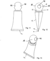
- the embodiment as shown in Figs. 11 to 13 differs from that according to the preceding embodiments in that the container is not closed by means of a cover but by welding the lower end of the container body. Further, the head section 18 has additional depressions 48 to promote a firm grip of the head section by a user. As can be seen in Figs. 11 to 13 , a section 42 starting from the bottom end 14 of the container is welded onto itself in order to close the container. In such a way, no additional cover is necessary. For sealing the bottom section 42, the container body should have a certain flexibility. In order to achieve this, the wall thickness d1 of the container body at its bottom end can be made smaller than the wall thickness at the tubular top end of the container.
- the container body at the tubular top end can be made with a material that is different from the remaining part of the tubular container body, the last being made of a more flexible material.
- a container can be molded in one single shot or in two shots depending on the overall size of the container.
- the tubular part of the container body can be made by extrusion (for example in LDPE with a constant wall thickness d1a) and then be provided by overmolding with an integrally molded top end and head section (for example in another material such as polypropylene or HDPE and with a wall thickness at the top end d1b which is larger than d1a). It is also possible to manufacture the top end and head section, and to combine it with the extruded tubular part of the container body by welding and especially heat fusing or ultrasonic welding.
- the connecting region 20 has a distinct length l which is at most 0.3 mm and according to the illustrative example of Fig. 15 , can be oriented in a longitudinal direction parallel to the rotational axis O or, according to the embodiment of Fig. 14 , the connecting region can be oriented in a radial direction.
- Fig. 14 is advantageous over that according to Fig. 15 in that a broken connecting region which might have sharp edges seems to be not problematic as long as the connecting region extends towards the interior of the container body.
- the opened container can be brought to the mouth of the user for direct oral supply of medication or single dose product.
- the connecting region 20 is in a radial direction and bridges a distance between the lower end of the head section 18 and the upper end of the tubular container body 12.
- the maximum diameter of the head section d head is smaller than the outer diameter d out of the container body 12 but smaller than the inner diameter d in of the container body 12. Once broken, the head section cannot be used to reclose the container body.
- the force F applied by the user will act at the apex position of the head section with the greatest diameter of the head section d head , which forms the protrusion 38 or in the illustrative example according to Fig. 15 , will act in the middle of the longitudinal extension of the protrusion 38, i.e. the region with the greatest diameter of the head section.
- the tamper-evident single-use container according to the invention cannot be closed in a way such that a user will immediately recognize if the container has been tampered with.
Landscapes
- Engineering & Computer Science (AREA)
- Mechanical Engineering (AREA)
- Food Science & Technology (AREA)
- Ceramic Engineering (AREA)
- Packages (AREA)
- Closures For Containers (AREA)
Claims (15)
- Récipient (10) inviolable à usage unique pour contenir des produits en dose unitaire, en particulier des produits pharmaceutiques solides, comprenant :- un corps (12) de récipient en matière plastique présentant une extrémité inférieure (14) et une extrémité supérieure tubulaire (16) ; et- une section de tête (18) fermant l'extrémité supérieure tubulaire (16) ; dans lequel la section de tête (18) est reliée d'un seul tenant à l'extrémité supérieure tubulaire (16) du corps (12) de récipient au niveau d'une région de liaison (20) ;dans lequel- l'épaisseur de la matière plastique au niveau de la région de liaison (20) est réduite d'au moins 50 % par rapport à l'épaisseur de paroi du corps (12) de récipient à l'extrémité supérieure tubulaire (16) ;- la section de tête (18) est pourvue de saillies (38) et/ou de dépressions (48) ;- les dimensions externes maximales de la section de tête (18) sont supérieures à un diamètre interne (din) du corps (12) de récipient ;- caractérisé en ce que la région de liaison (20) est sur un côté interne (28) de la paroi du corps (12) de récipient et présente une longueur (l) dans une direction radiale.
- Récipient inviolable à usage unique selon la revendication 1, caractérisé en ce que le corps (12) de récipient présente une forme cylindrique à base ronde, ovale ou polygonale.
- Récipient inviolable à usage unique selon la revendication 1 ou la revendication 2, caractérisé en ce que la section de tête (18) présente une forme externe ronde, de préférence une forme externe généralement sphérique.
- Récipient inviolable à usage unique selon l'une quelconque des revendications précédentes, comprenant en outre une gorge (22) sur la section de tête (18).
- Récipient inviolable à usage unique selon l'une quelconque des revendications précédentes, dans lequel l'angle (A) entre la section de paroi du corps (12) de récipient et la section de paroi de la section de tête (18) au niveau de la région de liaison (20) est d'au moins 10°.
- Récipient inviolable à usage unique selon l'une quelconque des revendications précédentes, dans lequel la région de liaison (20) couvre une distance entre le corps (12) de récipient et la section de tête (18), la longueur l de la région de liaison dans la direction de la distance étant définie par
0 < l ≤ 1 mm, de préférence 0 < l ≤ 0,5 mm. - Récipient inviolable à usage unique selon l'une quelconque des revendications précédentes, caractérisé en ce que les dimensions externes maximales de la section de tête (18) sont telles que la section de tête (18) ne fait pas saillie au-delà de l'extension externe du corps (12) de récipient.
- Récipient inviolable à usage unique selon l'une quelconque des revendications précédentes, dans lequel le corps (12) de récipient présente un diamètre interne din et un diamètre externe dout, et dans lequel un diamètre externe maximal dhead de la section de tête (18) est sélectionné pour satisfaire à l'équation

- Récipient inviolable à usage unique selon l'une quelconque des revendications précédentes, caractérisé en ce que l'épaisseur de la matière plastique au niveau de la région de liaison (20) est inférieure à 0,5 mm, de préférence est entre 0,1 mm et 0,5 mm et de manière davantage préférée entre 0,1 mm et 0,3 mm.
- Récipient inviolable à usage unique selon l'une quelconque des revendications précédentes, caractérisé en ce que le corps (12) de récipient est pourvu d'un épaulement annulaire interne (26) proche de l'extrémité inférieure (14).
- Récipient inviolable à usage unique selon l'une quelconque des revendications 1 à 10, caractérisé en ce que l'extrémité inférieure (14) du récipient (10) est fermée par soudage.
- Récipient inviolable à usage unique selon l'une quelconque des revendications 1 à 10, comprenant en outre un couvercle (24) fermant l'extrémité inférieure (14) du corps (12) de récipient.
- Récipient inviolable à usage unique selon la revendication 12, caractérisé en ce que le couvercle (24) ne fait pas saillie au-delà de l'extrémité inférieure (14) dans une direction longitudinale du corps (12) de récipient.
- Récipient inviolable à usage unique selon la revendication 12 ou la revendication 13, dans lequel le couvercle (24) est fixé au corps (12) de récipient par soudage, sertissage ou ajustement à force.
- Utilisation du récipient inviolable à usage unique selon l'une quelconque des revendications 1 à 14, pour stocker une substance pharmaceutique ou nutraceutique, de préférence des pilules, pastilles, globules, granulés, poudres ou capsules en vrac.
Priority Applications (1)
| Application Number | Priority Date | Filing Date | Title |
|---|---|---|---|
| EP16306737.4A EP3339206B1 (fr) | 2016-12-20 | 2016-12-20 | Récipient à usage unique inviolable destiné à contenir des doses unitaires |
Applications Claiming Priority (1)
| Application Number | Priority Date | Filing Date | Title |
|---|---|---|---|
| EP16306737.4A EP3339206B1 (fr) | 2016-12-20 | 2016-12-20 | Récipient à usage unique inviolable destiné à contenir des doses unitaires |
Publications (2)
| Publication Number | Publication Date |
|---|---|
| EP3339206A1 EP3339206A1 (fr) | 2018-06-27 |
| EP3339206B1 true EP3339206B1 (fr) | 2024-08-21 |
Family
ID=57794094
Family Applications (1)
| Application Number | Title | Priority Date | Filing Date |
|---|---|---|---|
| EP16306737.4A Active EP3339206B1 (fr) | 2016-12-20 | 2016-12-20 | Récipient à usage unique inviolable destiné à contenir des doses unitaires |
Country Status (1)
| Country | Link |
|---|---|
| EP (1) | EP3339206B1 (fr) |
Family Cites Families (10)
| Publication number | Priority date | Publication date | Assignee | Title |
|---|---|---|---|---|
| FR1181592A (fr) * | 1958-07-21 | 1959-06-17 | Tuboplast France | Récipient à bouchon incorporé |
| EP0076418B1 (fr) * | 1981-10-02 | 1987-06-03 | Ermenegildo Montalbetti | Procédé pour la fabrication de récipients étanches en matière plastique, en particulier des flacons, fioles et/ou articles analogues et récipients ainsi obtenus |
| US4703610A (en) * | 1986-07-21 | 1987-11-03 | Morris Bach | Unitary tamper proof container |
| FR2639026B1 (fr) * | 1988-11-15 | 1990-12-28 | Air Sec Sa | Tube a usage unique |
| FR2661846B1 (fr) * | 1990-05-10 | 1992-08-14 | Oreal | Dispositif applicateur a bille pour un produit liquide ou pateux et procede de fabrication dudit dispositif. |
| US5859145A (en) | 1993-07-13 | 1999-01-12 | Chevron Chemical Company | Compositions having ethylenic backbone and benzylic, allylic, or ether-containing side-chains, oxygen scavenging compositions containing same, and process for making these compositions by esterification or transesterification of a polymer melt |
| US6083585A (en) * | 1996-09-23 | 2000-07-04 | Bp Amoco Corporation | Oxygen scavenging condensation copolymers for bottles and packaging articles |
| US6139770A (en) | 1997-05-16 | 2000-10-31 | Chevron Chemical Company Llc | Photoinitiators and oxygen scavenging compositions |
| CA2325404C (fr) | 1998-03-25 | 2007-07-10 | Chevron Phillips Chemical Company Lp | Desoxygenants degageant moins de produits d'oxydation et destines a des films de plastique et des recipients pour boissons et aliments |
| DE102011115525A1 (de) * | 2011-10-11 | 2013-04-11 | Boehringer Ingelheim International Gmbh | Zweiteilige Flasche mit einem darin angeordneten Trockenmittel |
-
2016
- 2016-12-20 EP EP16306737.4A patent/EP3339206B1/fr active Active
Also Published As
| Publication number | Publication date |
|---|---|
| EP3339206A1 (fr) | 2018-06-27 |
Similar Documents
| Publication | Publication Date | Title |
|---|---|---|
| US7780008B2 (en) | Sealed assembly for storage and distribution with discharge control for solid pharmaceutical products | |
| US7413083B2 (en) | Desiccant vial assembly for effervescent tablets | |
| CA2541021C (fr) | Contenant a insert d'administration de pilules | |
| EP3728073B1 (fr) | Dispositif limiteur de débit et bouchon pour un récipient le comprenant | |
| US20090166312A1 (en) | Bottle shaped container with integrated sleeve | |
| KR20190126337A (ko) | 의료 및/또는 약품 제품용 용기 | |
| EP3515533B1 (fr) | Emballage pour seringue pré-remplie, procédé d'emballage d'une telle seringue et son utilisation | |
| KR102816444B1 (ko) | 활성 물질을 위한 챔버를 형성하기 위한 어셈블리 | |
| EP3339206B1 (fr) | Récipient à usage unique inviolable destiné à contenir des doses unitaires | |
| EP3902755B1 (fr) | Dispositif de distribution de comprimés | |
| CN222794194U (zh) | 用于瓶子组合件的螺旋顶帽以及瓶子组合件 | |
| EP3296229B1 (fr) | Dispositif limiteur de débit et récipient pour produits unitaires | |
| EP4393837B1 (fr) | Fermeture inviolable | |
| CN100564187C (zh) | 用于泡腾片的干燥剂小瓶组件 | |
| CN120584079A (zh) | 密封帽和包括密封帽的封闭件 |
Legal Events
| Date | Code | Title | Description |
|---|---|---|---|
| PUAI | Public reference made under article 153(3) epc to a published international application that has entered the european phase |
Free format text: ORIGINAL CODE: 0009012 |
|
| STAA | Information on the status of an ep patent application or granted ep patent |
Free format text: STATUS: THE APPLICATION HAS BEEN PUBLISHED |
|
| AK | Designated contracting states |
Kind code of ref document: A1 Designated state(s): AL AT BE BG CH CY CZ DE DK EE ES FI FR GB GR HR HU IE IS IT LI LT LU LV MC MK MT NL NO PL PT RO RS SE SI SK SM TR |
|
| AX | Request for extension of the european patent |
Extension state: BA ME |
|
| STAA | Information on the status of an ep patent application or granted ep patent |
Free format text: STATUS: REQUEST FOR EXAMINATION WAS MADE |
|
| 17P | Request for examination filed |
Effective date: 20181213 |
|
| RBV | Designated contracting states (corrected) |
Designated state(s): AL AT BE BG CH CY CZ DE DK EE ES FI FR GB GR HR HU IE IS IT LI LT LU LV MC MK MT NL NO PL PT RO RS SE SI SK SM TR |
|
| STAA | Information on the status of an ep patent application or granted ep patent |
Free format text: STATUS: EXAMINATION IS IN PROGRESS |
|
| 17Q | First examination report despatched |
Effective date: 20211123 |
|
| RAP1 | Party data changed (applicant data changed or rights of an application transferred) |
Owner name: AIRNOV, INC. |
|
| P01 | Opt-out of the competence of the unified patent court (upc) registered |
Effective date: 20230414 |
|
| GRAP | Despatch of communication of intention to grant a patent |
Free format text: ORIGINAL CODE: EPIDOSNIGR1 |
|
| STAA | Information on the status of an ep patent application or granted ep patent |
Free format text: STATUS: GRANT OF PATENT IS INTENDED |
|
| INTG | Intention to grant announced |
Effective date: 20240313 |
|
| GRAS | Grant fee paid |
Free format text: ORIGINAL CODE: EPIDOSNIGR3 |
|
| GRAA | (expected) grant |
Free format text: ORIGINAL CODE: 0009210 |
|
| STAA | Information on the status of an ep patent application or granted ep patent |
Free format text: STATUS: THE PATENT HAS BEEN GRANTED |
|
| AK | Designated contracting states |
Kind code of ref document: B1 Designated state(s): AL AT BE BG CH CY CZ DE DK EE ES FI FR GB GR HR HU IE IS IT LI LT LU LV MC MK MT NL NO PL PT RO RS SE SI SK SM TR |
|
| REG | Reference to a national code |
Ref country code: GB Ref legal event code: FG4D |
|
| REG | Reference to a national code |
Ref country code: CH Ref legal event code: EP |
|
| REG | Reference to a national code |
Ref country code: IE Ref legal event code: FG4D |
|
| REG | Reference to a national code |
Ref country code: DE Ref legal event code: R096 Ref document number: 602016088975 Country of ref document: DE |
|
| REG | Reference to a national code |
Ref country code: LT Ref legal event code: MG9D |
|
| REG | Reference to a national code |
Ref country code: NL Ref legal event code: MP Effective date: 20240821 |
|
| PG25 | Lapsed in a contracting state [announced via postgrant information from national office to epo] |
Ref country code: NO Free format text: LAPSE BECAUSE OF FAILURE TO SUBMIT A TRANSLATION OF THE DESCRIPTION OR TO PAY THE FEE WITHIN THE PRESCRIBED TIME-LIMIT Effective date: 20241121 |
|
| REG | Reference to a national code |
Ref country code: AT Ref legal event code: MK05 Ref document number: 1715304 Country of ref document: AT Kind code of ref document: T Effective date: 20240821 |
|
| PG25 | Lapsed in a contracting state [announced via postgrant information from national office to epo] |
Ref country code: GR Free format text: LAPSE BECAUSE OF FAILURE TO SUBMIT A TRANSLATION OF THE DESCRIPTION OR TO PAY THE FEE WITHIN THE PRESCRIBED TIME-LIMIT Effective date: 20241122 Ref country code: FI Free format text: LAPSE BECAUSE OF FAILURE TO SUBMIT A TRANSLATION OF THE DESCRIPTION OR TO PAY THE FEE WITHIN THE PRESCRIBED TIME-LIMIT Effective date: 20240821 Ref country code: PT Free format text: LAPSE BECAUSE OF FAILURE TO SUBMIT A TRANSLATION OF THE DESCRIPTION OR TO PAY THE FEE WITHIN THE PRESCRIBED TIME-LIMIT Effective date: 20241223 Ref country code: PL Free format text: LAPSE BECAUSE OF FAILURE TO SUBMIT A TRANSLATION OF THE DESCRIPTION OR TO PAY THE FEE WITHIN THE PRESCRIBED TIME-LIMIT Effective date: 20240821 Ref country code: NL Free format text: LAPSE BECAUSE OF FAILURE TO SUBMIT A TRANSLATION OF THE DESCRIPTION OR TO PAY THE FEE WITHIN THE PRESCRIBED TIME-LIMIT Effective date: 20240821 |
|
| PG25 | Lapsed in a contracting state [announced via postgrant information from national office to epo] |
Ref country code: BG Free format text: LAPSE BECAUSE OF FAILURE TO SUBMIT A TRANSLATION OF THE DESCRIPTION OR TO PAY THE FEE WITHIN THE PRESCRIBED TIME-LIMIT Effective date: 20240821 |
|
| PG25 | Lapsed in a contracting state [announced via postgrant information from national office to epo] |
Ref country code: LV Free format text: LAPSE BECAUSE OF FAILURE TO SUBMIT A TRANSLATION OF THE DESCRIPTION OR TO PAY THE FEE WITHIN THE PRESCRIBED TIME-LIMIT Effective date: 20240821 |
|
| PG25 | Lapsed in a contracting state [announced via postgrant information from national office to epo] |
Ref country code: AT Free format text: LAPSE BECAUSE OF FAILURE TO SUBMIT A TRANSLATION OF THE DESCRIPTION OR TO PAY THE FEE WITHIN THE PRESCRIBED TIME-LIMIT Effective date: 20240821 Ref country code: IS Free format text: LAPSE BECAUSE OF FAILURE TO SUBMIT A TRANSLATION OF THE DESCRIPTION OR TO PAY THE FEE WITHIN THE PRESCRIBED TIME-LIMIT Effective date: 20241221 |
|
| PG25 | Lapsed in a contracting state [announced via postgrant information from national office to epo] |
Ref country code: HR Free format text: LAPSE BECAUSE OF FAILURE TO SUBMIT A TRANSLATION OF THE DESCRIPTION OR TO PAY THE FEE WITHIN THE PRESCRIBED TIME-LIMIT Effective date: 20240821 |
|
| PG25 | Lapsed in a contracting state [announced via postgrant information from national office to epo] |
Ref country code: RS Free format text: LAPSE BECAUSE OF FAILURE TO SUBMIT A TRANSLATION OF THE DESCRIPTION OR TO PAY THE FEE WITHIN THE PRESCRIBED TIME-LIMIT Effective date: 20241121 Ref country code: ES Free format text: LAPSE BECAUSE OF FAILURE TO SUBMIT A TRANSLATION OF THE DESCRIPTION OR TO PAY THE FEE WITHIN THE PRESCRIBED TIME-LIMIT Effective date: 20240821 |
|
| PG25 | Lapsed in a contracting state [announced via postgrant information from national office to epo] |
Ref country code: RS Free format text: LAPSE BECAUSE OF FAILURE TO SUBMIT A TRANSLATION OF THE DESCRIPTION OR TO PAY THE FEE WITHIN THE PRESCRIBED TIME-LIMIT Effective date: 20241121 Ref country code: PT Free format text: LAPSE BECAUSE OF FAILURE TO SUBMIT A TRANSLATION OF THE DESCRIPTION OR TO PAY THE FEE WITHIN THE PRESCRIBED TIME-LIMIT Effective date: 20241223 Ref country code: PL Free format text: LAPSE BECAUSE OF FAILURE TO SUBMIT A TRANSLATION OF THE DESCRIPTION OR TO PAY THE FEE WITHIN THE PRESCRIBED TIME-LIMIT Effective date: 20240821 Ref country code: NO Free format text: LAPSE BECAUSE OF FAILURE TO SUBMIT A TRANSLATION OF THE DESCRIPTION OR TO PAY THE FEE WITHIN THE PRESCRIBED TIME-LIMIT Effective date: 20241121 Ref country code: NL Free format text: LAPSE BECAUSE OF FAILURE TO SUBMIT A TRANSLATION OF THE DESCRIPTION OR TO PAY THE FEE WITHIN THE PRESCRIBED TIME-LIMIT Effective date: 20240821 Ref country code: LV Free format text: LAPSE BECAUSE OF FAILURE TO SUBMIT A TRANSLATION OF THE DESCRIPTION OR TO PAY THE FEE WITHIN THE PRESCRIBED TIME-LIMIT Effective date: 20240821 Ref country code: IS Free format text: LAPSE BECAUSE OF FAILURE TO SUBMIT A TRANSLATION OF THE DESCRIPTION OR TO PAY THE FEE WITHIN THE PRESCRIBED TIME-LIMIT Effective date: 20241221 Ref country code: HR Free format text: LAPSE BECAUSE OF FAILURE TO SUBMIT A TRANSLATION OF THE DESCRIPTION OR TO PAY THE FEE WITHIN THE PRESCRIBED TIME-LIMIT Effective date: 20240821 Ref country code: GR Free format text: LAPSE BECAUSE OF FAILURE TO SUBMIT A TRANSLATION OF THE DESCRIPTION OR TO PAY THE FEE WITHIN THE PRESCRIBED TIME-LIMIT Effective date: 20241122 Ref country code: FI Free format text: LAPSE BECAUSE OF FAILURE TO SUBMIT A TRANSLATION OF THE DESCRIPTION OR TO PAY THE FEE WITHIN THE PRESCRIBED TIME-LIMIT Effective date: 20240821 Ref country code: ES Free format text: LAPSE BECAUSE OF FAILURE TO SUBMIT A TRANSLATION OF THE DESCRIPTION OR TO PAY THE FEE WITHIN THE PRESCRIBED TIME-LIMIT Effective date: 20240821 Ref country code: BG Free format text: LAPSE BECAUSE OF FAILURE TO SUBMIT A TRANSLATION OF THE DESCRIPTION OR TO PAY THE FEE WITHIN THE PRESCRIBED TIME-LIMIT Effective date: 20240821 Ref country code: AT Free format text: LAPSE BECAUSE OF FAILURE TO SUBMIT A TRANSLATION OF THE DESCRIPTION OR TO PAY THE FEE WITHIN THE PRESCRIBED TIME-LIMIT Effective date: 20240821 |
|
| PG25 | Lapsed in a contracting state [announced via postgrant information from national office to epo] |
Ref country code: RO Free format text: LAPSE BECAUSE OF FAILURE TO SUBMIT A TRANSLATION OF THE DESCRIPTION OR TO PAY THE FEE WITHIN THE PRESCRIBED TIME-LIMIT Effective date: 20240821 Ref country code: SM Free format text: LAPSE BECAUSE OF FAILURE TO SUBMIT A TRANSLATION OF THE DESCRIPTION OR TO PAY THE FEE WITHIN THE PRESCRIBED TIME-LIMIT Effective date: 20240821 Ref country code: DK Free format text: LAPSE BECAUSE OF FAILURE TO SUBMIT A TRANSLATION OF THE DESCRIPTION OR TO PAY THE FEE WITHIN THE PRESCRIBED TIME-LIMIT Effective date: 20240821 |
|
| PG25 | Lapsed in a contracting state [announced via postgrant information from national office to epo] |
Ref country code: EE Free format text: LAPSE BECAUSE OF FAILURE TO SUBMIT A TRANSLATION OF THE DESCRIPTION OR TO PAY THE FEE WITHIN THE PRESCRIBED TIME-LIMIT Effective date: 20240821 |
|
| PGFP | Annual fee paid to national office [announced via postgrant information from national office to epo] |
Ref country code: CH Payment date: 20250101 Year of fee payment: 9 |
|
| PG25 | Lapsed in a contracting state [announced via postgrant information from national office to epo] |
Ref country code: CZ Free format text: LAPSE BECAUSE OF FAILURE TO SUBMIT A TRANSLATION OF THE DESCRIPTION OR TO PAY THE FEE WITHIN THE PRESCRIBED TIME-LIMIT Effective date: 20240821 |
|
| PG25 | Lapsed in a contracting state [announced via postgrant information from national office to epo] |
Ref country code: SK Free format text: LAPSE BECAUSE OF FAILURE TO SUBMIT A TRANSLATION OF THE DESCRIPTION OR TO PAY THE FEE WITHIN THE PRESCRIBED TIME-LIMIT Effective date: 20240821 Ref country code: IT Free format text: LAPSE BECAUSE OF FAILURE TO SUBMIT A TRANSLATION OF THE DESCRIPTION OR TO PAY THE FEE WITHIN THE PRESCRIBED TIME-LIMIT Effective date: 20240821 |
|
| REG | Reference to a national code |
Ref country code: DE Ref legal event code: R097 Ref document number: 602016088975 Country of ref document: DE |
|
| PLBE | No opposition filed within time limit |
Free format text: ORIGINAL CODE: 0009261 |
|
| STAA | Information on the status of an ep patent application or granted ep patent |
Free format text: STATUS: NO OPPOSITION FILED WITHIN TIME LIMIT |
|
| PG25 | Lapsed in a contracting state [announced via postgrant information from national office to epo] |
Ref country code: MC Free format text: LAPSE BECAUSE OF FAILURE TO SUBMIT A TRANSLATION OF THE DESCRIPTION OR TO PAY THE FEE WITHIN THE PRESCRIBED TIME-LIMIT Effective date: 20240821 |
|
| 26N | No opposition filed |
Effective date: 20250522 |
|
| PG25 | Lapsed in a contracting state [announced via postgrant information from national office to epo] |
Ref country code: LU Free format text: LAPSE BECAUSE OF NON-PAYMENT OF DUE FEES Effective date: 20241220 |
|
| PG25 | Lapsed in a contracting state [announced via postgrant information from national office to epo] |
Ref country code: SE Free format text: LAPSE BECAUSE OF FAILURE TO SUBMIT A TRANSLATION OF THE DESCRIPTION OR TO PAY THE FEE WITHIN THE PRESCRIBED TIME-LIMIT Effective date: 20240821 |
|
| REG | Reference to a national code |
Ref country code: BE Ref legal event code: MM Effective date: 20241231 |
|
| PG25 | Lapsed in a contracting state [announced via postgrant information from national office to epo] |
Ref country code: BE Free format text: LAPSE BECAUSE OF NON-PAYMENT OF DUE FEES Effective date: 20241231 |
|
| REG | Reference to a national code |
Ref country code: CH Ref legal event code: U11 Free format text: ST27 STATUS EVENT CODE: U-0-0-U10-U11 (AS PROVIDED BY THE NATIONAL OFFICE) Effective date: 20260101 |
|
| PGFP | Annual fee paid to national office [announced via postgrant information from national office to epo] |
Ref country code: GB Payment date: 20251222 Year of fee payment: 10 |
|
| PGFP | Annual fee paid to national office [announced via postgrant information from national office to epo] |
Ref country code: FR Payment date: 20251223 Year of fee payment: 10 |
|
| PGFP | Annual fee paid to national office [announced via postgrant information from national office to epo] |
Ref country code: IE Payment date: 20251216 Year of fee payment: 10 |
|
| PGFP | Annual fee paid to national office [announced via postgrant information from national office to epo] |
Ref country code: DE Payment date: 20251223 Year of fee payment: 10 |