EP3339231A1 - Connecteur pour câble de levage d'un appareil de levage - Google Patents
Connecteur pour câble de levage d'un appareil de levage Download PDFInfo
- Publication number
- EP3339231A1 EP3339231A1 EP16206745.8A EP16206745A EP3339231A1 EP 3339231 A1 EP3339231 A1 EP 3339231A1 EP 16206745 A EP16206745 A EP 16206745A EP 3339231 A1 EP3339231 A1 EP 3339231A1
- Authority
- EP
- European Patent Office
- Prior art keywords
- connector
- hoisting rope
- clamp part
- load bearing
- hoisting
- Prior art date
- Legal status (The legal status is an assumption and is not a legal conclusion. Google has not performed a legal analysis and makes no representation as to the accuracy of the status listed.)
- Withdrawn
Links
- 239000011159 matrix material Substances 0.000 claims description 46
- 239000012783 reinforcing fiber Substances 0.000 claims description 42
- 229920000642 polymer Polymers 0.000 claims description 29
- 239000000835 fiber Substances 0.000 claims description 24
- 238000012544 monitoring process Methods 0.000 claims description 22
- 239000011248 coating agent Substances 0.000 claims description 18
- 238000000576 coating method Methods 0.000 claims description 18
- 238000012806 monitoring device Methods 0.000 claims description 18
- 230000007547 defect Effects 0.000 claims description 9
- 239000002131 composite material Substances 0.000 claims description 6
- 229920000049 Carbon (fiber) Polymers 0.000 claims description 5
- 239000004917 carbon fiber Substances 0.000 claims description 5
- 239000007769 metal material Substances 0.000 claims description 3
- 229910052755 nonmetal Inorganic materials 0.000 claims description 3
- 239000000463 material Substances 0.000 description 11
- 229920001971 elastomer Polymers 0.000 description 4
- 238000009434 installation Methods 0.000 description 4
- 239000000126 substance Substances 0.000 description 4
- 239000004593 Epoxy Substances 0.000 description 3
- 239000000806 elastomer Substances 0.000 description 3
- 238000000034 method Methods 0.000 description 3
- 229920005601 base polymer Polymers 0.000 description 2
- 239000012530 fluid Substances 0.000 description 2
- 238000004519 manufacturing process Methods 0.000 description 2
- 239000002184 metal Substances 0.000 description 2
- 229920000728 polyester Polymers 0.000 description 2
- 239000002861 polymer material Substances 0.000 description 2
- 230000001902 propagating effect Effects 0.000 description 2
- 239000007787 solid Substances 0.000 description 2
- 229920001567 vinyl ester resin Polymers 0.000 description 2
- 238000011179 visual inspection Methods 0.000 description 2
- 239000000654 additive Substances 0.000 description 1
- 238000005452 bending Methods 0.000 description 1
- 230000005540 biological transmission Effects 0.000 description 1
- 239000004020 conductor Substances 0.000 description 1
- 230000008878 coupling Effects 0.000 description 1
- 238000010168 coupling process Methods 0.000 description 1
- 238000005859 coupling reaction Methods 0.000 description 1
- 238000009826 distribution Methods 0.000 description 1
- 230000008030 elimination Effects 0.000 description 1
- 238000003379 elimination reaction Methods 0.000 description 1
- 238000005516 engineering process Methods 0.000 description 1
- 239000003822 epoxy resin Substances 0.000 description 1
- 239000002657 fibrous material Substances 0.000 description 1
- 238000005470 impregnation Methods 0.000 description 1
- 238000007689 inspection Methods 0.000 description 1
- 238000011900 installation process Methods 0.000 description 1
- VNWKTOKETHGBQD-UHFFFAOYSA-N methane Chemical compound C VNWKTOKETHGBQD-UHFFFAOYSA-N 0.000 description 1
- 229920001568 phenolic resin Polymers 0.000 description 1
- 229920000647 polyepoxide Polymers 0.000 description 1
- 229920002635 polyurethane Polymers 0.000 description 1
- 239000004814 polyurethane Substances 0.000 description 1
- 230000002787 reinforcement Effects 0.000 description 1
- 230000001131 transforming effect Effects 0.000 description 1
Images


Classifications
-
- B—PERFORMING OPERATIONS; TRANSPORTING
- B66—HOISTING; LIFTING; HAULING
- B66B—ELEVATORS; ESCALATORS OR MOVING WALKWAYS
- B66B7/00—Other common features of elevators
- B66B7/06—Arrangements of ropes or cables
- B66B7/08—Arrangements of ropes or cables for connection to the cars or cages, e.g. couplings
- B66B7/085—Belt termination devices
Definitions
- the invention relates to a connector for a hoisting rope of a hoisting apparatus.
- Said hoisting rope is preferably a hoisting rope which has electrically conductive properties.
- Said hoisting apparatus is preferably an elevator for transporting passengers and/or goods.
- Hoisting ropes typically include one or several load bearing members that are elongated in the longitudinal direction of the rope, each load bearing member forming a structure that continues unbroken throughout the length of the rope.
- Load bearing members are the members of the rope which are able to bear together the load exerted on the rope in its longitudinal direction.
- the load such as a weight suspended by the rope, causes tension on the load bearing member in the longitudinal direction of the rope, which tension can be transmitted by the load bearing member in question all the way from one end of the rope to the other end of the rope.
- Ropes may further comprise non-bearing components, such as an elastic coating, which cannot transmit tension in the above described way.
- hoisting ropes exist where the load bearing members are embedded in non-conducting coating, such as polymer coating, forming the surface of the hoisting rope and extending between adjacent load bearing members thereby isolating them from each other both mechanically and electrically.
- non-conducting coating such as polymer coating
- monitoring of the condition of the load bearing members has been proposed.
- the visual inspection of the internal tensile elements is generally not possible and hence the need arises for non-visual inspection.
- the condition monitoring has been proposed to be arranged by monitoring electrical parameters of the load bearing members.
- One known method for checking the condition of the tensile elements is the resistance-based inspection, which is based on a measure of the electrical resistance of the tensile elements. A change in the electrical resistance or a deviation from an expected value is interpreted as a damage of the tensile elements.
- the object of the invention is to introduce a connector for a hoisting rope of a hoisting apparatus, which provides reliable electrical connection to a hoisting rope of a hoisting apparatus.
- Advantageous embodiments are furthermore presented, inter alia, wherein qualitative information about the damage magnitude is provided.
- hoisting rope comprises a non-conductive coating, and a plurality of adjacent conductive load bearing members for bearing the load exerted on the hoisting rope in longitudinal direction thereof embedded in the coating and extending parallel to each other and to the longitudinal direction of the hoisting rope, the coating forming the surface of the hoisting rope and extending between adjacent load bearing members thereby isolating them from each other,
- connector comprises: a connector plate part, a top clamp part and a bottom clamp part for clamping said connector plate part to an end of said hoisting rope; wherein said hoisting rope has a notch opening ground to said end of said hoisting rope, so that said notch opening exposes said conductive load bearing members, wherein said connector plate part has a bended portion matching with said notch opening, and wherein one of said top clamp part and said bottom clamp part has a tooth part matching with said bended portion of said connector plate part and with said notch opening;
- said conductive load bearing members are made of non-metal material.
- said conductive load bearing members are made of composite material comprising electrically conducting reinforcing fibers in polymer matrix, said reinforcing fibers preferably being carbon fibers.
- said hoisting rope is belt-shaped, i.e. larger in width direction than thickness direction.
- said connector comprises a fixing bolt and a nut, said fixing bolt and said nut arranged to hold said top clamp part and said bottom clamp part together.
- one of the said top clamp part and said bottom clamp part comprise a hexagonal pocket arranged for one of the said fixing bolt and said nut.
- one of said top clamp part and said bottom clamp part comprise a pivot shape and the another one of said the said top clamp part and said bottom clamp part comprise a chuck shape.
- said top clamp part and said bottom clamp part comprise hinge joint counterparts.
- said connector plate part is attached to said top clamp part.
- said notch opening is a V-shape notch opening, a U-shape notch opening or a semicircular shape notch opening.
- said bended portion of said connector plate part includes abrasive jaws.
- said connector plate part is cut to form two separate blade connectors of said connector.
- said connector is connected to a condition monitoring device.
- a connector in an arrangement for condition monitoring of a hoisting rope of a hoisting apparatus, which hoisting rope comprises a non-conductive coating, and a plurality of adjacent conductive load bearing members for bearing the load exerted on the hoisting rope in longitudinal direction thereof embedded in the coating and extending parallel to each other and to the longitudinal direction of the hoisting rope, the coating forming the surface of the hoisting rope and extending between adjacent load bearing members thereby isolating them from each other, in which connector comprises: a connector plate part, a top clamp part and a bottom clamp part for clamping said connector plate part to an end of said hoisting rope; wherein said hoisting rope has a notch opening ground to said end of said hoisting rope, so that said notch opening exposes said conductive load bearing members, wherein said connector plate part has a bended portion matching with said notch opening, and wherein one of said top clamp part and said bottom clamp part has a tooth part matching with said bended portion of
- FIG. 1 illustrates an arrangement for condition monitoring of a hoisting rope of a hoisting apparatus according to one embodiment of the present invention.
- the hoisting rope 1 is belt-shaped, i.e. larger in width direction than thickness direction and has a first end 7 and other end 8.
- the hoisting rope 1 comprises a non-conductive coating 2, and a plurality of conductive load bearing members 3-6 for bearing the load exerted on the hoisting rope 1 in longitudinal direction thereof, which are adjacent in width direction of the hoisting rope 1.
- the load bearing members 3-6 are embedded in the non-conductive coating 2 and extend parallel to each other as well as to the longitudinal direction of the hoisting rope 1 unbroken throughout the length of the hoisting rope 1.
- the coating 2 forms the surface of the hoisting rope 1 and extends between adjacent load bearing members 3-6, thereby isolating them from each other both mechanically and electrically.
- the said conductive load bearing members 3-6 may be made of non-metal material.
- the said conductive load bearing members 3-6 may be made of composite material comprising electrically conducting reinforcing fibers in polymer matrix, said reinforcing fibers preferably being carbon fibers.
- the hoisting rope according to the present invention comprises protrusions and/or grooves for guiding the rope. Furthermore, in a preferred embodiment, the hoisting rope is provided with a cogged surface in order to produce a positive contact with a drive sheave. Furthermore, in a preferred embodiment, the hoisting rope is symmetrical in its thickness direction.
- the arrangement for condition monitoring of a hoisting rope of a hoisting apparatus comprises an at least one condition monitoring device 9 for monitoring the condition of the hoisting rope 1.
- the arrangement for condition monitoring of a hoisting rope of a hoisting apparatus according to the present invention also comprises an at least one connection interface 10-13.
- the arrangement for condition monitoring of a hoisting rope of a hoisting apparatus according to the embodiment of the present invention presented in Figure 1 comprises a condition monitoring device 9 of said at least one condition monitoring device 9 and a first connection interface 10, a second connection interface 11, a third connection interface 12 and a fourth connection interface 13 of said at least one connection interface 10-13.
- two individual conductive load bearing members 3, 4 are coupled together in the first connection interface 10 at the first end 7 of the hoisting rope 1.
- two individual conductive load bearing members 5, 6 are coupled together in the second connection interface 10 at the first end 7 of the hoisting rope 1.
- two individual conductive load bearing members 3, 4 are coupled together in the third connection interface 12 and two individual conductive load bearing members 5, 6 are coupled together in the fourth connection interface 13.
- the first connection interface 10 and the second connection interface 11 are coupled to the condition monitoring device 9.
- FIG. 1 the further coupling of the third connection interface 12 and the fourth connection interface 13 at the second end 8 of the hoisting rope 1 are not shown.
- Said third connection interface 12 and said fourth connection interface 13 at the second end 8 of the hoisting rope 1 may be coupled to the same condition monitoring device 9 as said first connection interface 10 and said second connection interface 11 at the first end 7 of the hoisting rope 1.
- said third connection interface 12 and said fourth connection interface 13 at the second end 8 of the hoisting rope 1 may be coupled to another condition monitoring device or to another device, e.g. to a signal generator or an analyzer device.
- said third connection interface 12 and said fourth connection interface 13 at the second end 8 of the hoisting rope 1 may simply be terminated or left uncoupled.
- an electrical pulse or an electromagnetic signal is inserted into said conductive load bearing members 3-6 to propagate from the first end 7 to the second end 8 of the hoisting rope 1 or from the second end 8 to the first end 7 of the hoisting rope 1.
- the condition monitoring device 9 receives an electrical pulse or an electromagnetic signal propagating in said conductive load bearing members 3-6 through said first connection interface 10 and said second connection interface 11. By analyzing and monitoring said received electrical pulse or said received electromagnetic signal said condition monitoring device 9 may determine the condition of the hoisting rope 1.
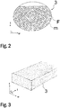
- FIG 2 illustrates a preferred inner structure of the load bearing member according to the present invention.
- the width direction w and the thickness direction t of a load bearing member 3 is shown.
- the cross section of the load bearing member 3 as viewed in the longitudinal direction I of the load bearing member 3 is shown in particular.
- the rope could alternatively have some other number of load bearing members 3, either more or less than what is disclosed in the Figures.
- the load bearing members 3-6 are made of composite material comprising reinforcing fibers F embedded in polymer matrix m.
- the reinforcing fibers F are more specifically distributed in polymer matrix m and bound together by the polymer matrix, particularly such that an elongated rod-like piece is formed.
- each load bearing member 3-6 is one solid elongated rod-like piece.
- the reinforcing fibers F are distributed preferably substantially evenly in the polymer matrix m. Thereby a load bearing member with homogeneous properties and structure is achieved throughout its cross section. In this way, it can be also ensured that each of the fibers can be in contact and bonded with the matrix m.
- Said reinforcing fibers F are most preferably carbon fibers as they are electrically conducting and have excellent properties in terms of load bearing capacity, weight and tensile stiffness, which makes them particularly well suitable for use in elevator hoisting ropes.
- said reinforcing fibers F can be of any other fiber material which is electrically conducting.
- the matrix m comprises preferably of epoxy, but alternative materials could be used depending on the preferred properties.
- substantially all the reinforcing fibers F of each load bearing member 3-6 are parallel with the longitudinal direction of the load bearing member 3-6. Thereby the fibers are also parallel with the longitudinal direction of the hoisting rope 1 as each load bearing member is oriented parallel with the longitudinal direction of the hoisting rope 1.
- the fibers in the final hoisting rope 1 will be aligned with the force when the hoisting rope 1 is pulled, which ensures that the structure provides high tensile stiffness. This is also advantageous for achieving unproblematic behavior of the internal structure, particularly internal movement, when the hoisting rope 1 is bent.
- the fibers F used in the preferred embodiments are substantially untwisted in relation to each other, which provides them said orientation parallel with the longitudinal direction of the hoisting rope 1.
- This is in contrast to the conventionally twisted elevator ropes, where the wires or fibers are strongly twisted and have normally a twisting angle from 15 up to 30 degrees, the fiber/wire bundles of these conventionally twisted elevator ropes thereby having the potential for transforming towards a straighter configuration under tension, which provides these ropes a high elongation under tension as well as leads to an unintegral structure.
- the reinforcing fibers F are preferably long continuous fibers in the longitudinal direction of the load bearing member, the fibers F preferably continuing for the whole length of the load bearing member 3-6 as well as the hoisting rope 1.
- the fibers F being oriented parallel with longitudinal direction of the hoisting rope 1, as far as possible, the cross section of the load bearing member 3-6 can be made to continue substantially the same in terms of its cross-section for the whole length of the hoisting rope 1. Thus, no substantial relative movement can occur inside the load bearing member 3-6 when it is bent.
- the reinforcing fibers F are preferably distributed in the aforementioned load bearing member 3-6 substantially evenly, in particular as evenly as possible, so that the load bearing member 3-6 would be as homogeneous as possible in the transverse direction thereof.
- An advantage of the structure presented is that the matrix m surrounding the reinforcing fibers F keeps the interpositioning of the reinforcing fibers F substantially unchanged. It equalizes with its slight elasticity the distribution of a force exerted on the fibers, reduces fiber-fiber contacts and internal wear of the hoisting rope, thus improving the service life of the hoisting rope 1.
- the composite matrix m, into which the individual fibers F are distributed as evenly as possible, is most preferably made of epoxy, which has good adhesion to the reinforcement fibers F and which is known to behave advantageously with carbon fiber.
- e.g. polyester or vinyl ester can be used, but alternatively any other suitable alternative materials can be used.
- Figure 2 presents inside the circle a partial cross-section of the load bearing member 3-6 close to the surface thereof as viewed in the longitudinal direction of the hoisting rope 1.
- the reinforcing fibers F of the load bearing member 3-6 are preferably organized in the polymer matrix m according to this cross-section.
- the rest (parts not showed) of the load bearing member 3-6 have a similar structure.
- Figure 3 illustrates a three dimensional view of a section of the load bearing member according to the present invention. From the presented Figure 2 and Figure 3 it can also be seen how the individual reinforcing fibers F of a load bearing member 3 are substantially evenly distributed in the polymer matrix m, which surrounds the reinforcing fibers F.
- the polymer matrix m fills the areas between individual reinforcing fibers F and binds substantially all the reinforcing fibers F that are inside the matrix m to each other as a uniform solid substance.
- a chemical bond exists between, the individual reinforcing fibers F (preferably each of them) and the matrix m, one advantage of which is uniformity of the structure.
- each fiber can have a thin coating, e.g. a primer (not presented) on the actual fiber structure between the reinforcing fiber structure and the polymer matrix m.
- a primer not presented
- the properties of the polymer matrix m can also be optimized as it is common in polymer technology.
- the matrix m can comprise a base polymer material (e.g. epoxy) as well as additives, which fine-tune the properties of the base polymer such that the properties of the matrix are optimized.
- the polymer matrix m is preferably of a hard non-elastomer as in this case a risk of buckling can be reduced for instance.
- the polymer matrix need not be non-elastomer necessarily, e.g. if the downsides of this kind of material are deemed acceptable or irrelevant for the intended use.
- the polymer matrix m can be made of elastomer material such as polyurethane or rubber for instance.
- the reinforcing fibers F being in the polymer matrix means here that the individual reinforcing fibers F are bound to each other with a polymer matrix m, e.g. in the manufacturing phase by immersing them together in the fluid material of the polymer matrix which is thereafter solidified.
- the gaps of individual reinforcing fibers bound to each other with the polymer matrix comprise the polymer of the matrix.
- the reinforcing fibers are preferably distributed substantially evenly in the polymer matrix m, whereby the load bearing member is as homogeneous as possible when viewed in the direction of the cross-section of the hoisting rope.
- the fiber density in the cross-section of the load bearing member 3-6 does not therefore vary substantially.
- the individual reinforcing fibers of the load bearing member 3-6 are mainly surrounded with polymer matrix m, but random fiber-fiber contacts can occur because controlling the position of the fibers in relation to each other in their simultaneous impregnation with polymer is difficult, and on the other hand, perfect elimination of random fiber-fiber contacts is not necessary from the viewpoint of the functioning of the solution. If, however, it is desired to reduce their random occurrence, the individual reinforcing fibers F can be pre-coated with material of the matrix m such that a coating of polymer material of said matrix is around each of them already before they are brought and bound together with the matrix material, e.g. before they are immersed in the fluid matrix material.
- the matrix m of the load bearing member 3-6 is most preferably hard in its material properties.
- a hard matrix m helps to support the reinforcing fibers F, especially when the hoisting rope bends, preventing buckling of the reinforcing fibers F of the bent rope, because the hard material supports the fibers F efficiently.
- the polymer matrix m is hard, and in particular non-elastomeric.
- the most preferred materials for the matrix are epoxy resin, polyester, phenolic plastic or vinyl ester.
- the polymer matrix m is preferably so hard that its module of elasticity E is over 2 GPa, most preferably over 2.5 GPa. In this case the module of elasticity E is preferably in the range 2.5-10 GPa, most preferably in the range 2.5-3.5 GPa.
- the matrix m which can provide these material properties.
- the surface area of the cross-section of the load bearing member 3-6 is of the aforementioned electrically conducting reinforcing fiber.
- Fibers F will be in contact with each other randomly along their length whereby electromagnetic wave signal inserted into the load bearing member will propagate within substantially the whole cross section of the load bearing member.
- 50%-80% of the surface area of the cross-section of the load bearing member 3-6 is of the aforementioned reinforcing fiber, most preferably such that 55%-70% is of the aforementioned reinforcing fiber, and substantially all the remaining surface area is of polymer matrix.
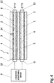
- Figure 4 illustrates an arrangement for condition monitoring of a hoisting rope of a hoisting apparatus according to another embodiment of the present invention having a defect in the hoisting rope.
- the arrangement for condition monitoring of a hoisting rope of a hoisting apparatus presented in Figure 4 is similar to that of presented in Figure 1 with the exception of that there is a defect 14 in the first parallel conductor transmission line 14 of the defected hoisting rope 1 of Figure 4 .
- the defected hoisting rope 1 is partially broken from a defect 14 in the middle part of the defected hoisting rope 1.
- an electrical pulse or an electromagnetic signal is inserted into said conductive load bearing members 3-6 to propagate from the first end 7 to the second end 8 of the hoisting rope 1 or from the second end 8 to the first end 7 of the hoisting rope 1.
- the condition monitoring device 9 receives an electrical pulse or an electromagnetic signal propagating in said conductive load bearing members 3-6 through said first connection interface 10 and said second connection interface 11. By analyzing and monitoring said received electrical pulse or said received electromagnetic signal said condition monitoring device 9 may substantiate the defect 14 and type of the damage and determine the condition of the hoisting rope 1.
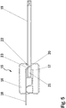
- FIG. 5 illustrates a side view of a connector for a hoisting rope of a hoisting apparatus according to one embodiment of the present invention.
- the connector 15 for a hoisting rope of a hoisting apparatus according to the presented embodiment comprises a top clamp part 16, a bottom clamp part 17 and a connector plate part 18.
- a hoisting rope 19 of a hoisting apparatus according to the presented embodiment has a notch opening 20 ground to the end part 21 of the hoisting rope 19.
- Said connector plate part 18 of said connector 15 for a hoisting rope has a bended portion 22 matching with said notch opening 20 in the end part 21 of said hoisting rope 19.
- said top clamp part 16 of said connector 15 for a hoisting rope has a tooth part 23 matching with said bended portion 22 of said connector plate part 18 and with said notch opening 20 in the end part 21 of said hoisting rope 19.
- FIG. 6 illustrates a cross-sectional view of a connector for a hoisting rope of a hoisting apparatus according to one embodiment of the present invention.
- the connector 15 for a hoisting rope of a hoisting apparatus according to the presented embodiment comprises a top clamp part 16, a bottom clamp part 17 and a connector plate part 18. Said connector plate part 18 may be directly attached to said top clamp part 16.
- a hoisting rope 19 of a hoisting apparatus according to the presented embodiment has a notch opening 20 ground to the end part 21 of the hoisting rope 19 so that said notch opening (20) exposes the conductive load bearing members of the hoisting rope.
- Said connector plate part 18 of said connector 15 for a hoisting rope has a bended portion 22 matching with said notch opening 20 in the end part 21 of said hoisting rope 19. Furthermore, said top clamp part 16 of said connector 15 for a hoisting rope has a tooth part 23 matching with said bended portion 22 of said connector plate part 18 and with said notch opening 20 in the end part 21 of said hoisting rope 19.
- the connector 15 for a hoisting rope of a hoisting apparatus also comprises a fixing bolt 24 and a nut 25, said fixing bolt 24 and said nut 25 arranged to hold said top clamp part 16 and said bottom clamp part 17 of the connector 15 for a hoisting rope together.
- One of the said fixing bolt 24 and said nut 25 may be arranged to lie in a hexagonal pocket arranged in one of the said top clamp part 16 and said bottom clamp part 17.
- the connector 15 for a hoisting rope of a hoisting apparatus has a pivot shape 26 arranged in one of the said top clamp part 16 and said bottom clamp part 17 of said connector 15 and respectively a chuck shape 27 arranged in another one of the said top clamp part 16 and said bottom clamp part 17 and matching said pivot shape.
- the pivot shape 26 of the bottom clamp part 17 and the matching chuck shape 27 of the top clamp part 16 allow the said top clamp part 16 and said bottom clamp part 17 to pivot as the said fixing bolt 24 and said nut 25 of said connector 15 are tightened.
- said top clamp part 16 and said bottom clamp part 17 of said connector 15 may comprise hinge joint counterparts.
- the ground notch opening 20 may have a V-shape, a U-shape or a semicircular shape for self-locking said top clamp part 16 at direction of the said hoisting rope 19.
- a V-shape, a U-shape or a semicircular shape of said ground notch opening 20 also open a wide area of the ground surfaces of said reinforcing fibers F heads.
- the ground notch opening 20 may have another shape than V-shape, a U-shape or a semicircular shape.
- the said bended portion 22 of said connector plate part 18 may include abrasive jaws to increase the attachment surface said reinforcing fibers F of the load bearing members 3-6 of the hoisting rope 19.
- the next step in the installation of the connector for a hoisting rope of a hoisting apparatus is to slide the end part 21 of the hoisting rope 19 between the top clamp part 16 and the bottom clamp part 17, said top clamp part 16 having said connector plate part 18 attached to it.
- Said end part 21 of the hoisting rope is slid so that said notch opening 20 in the end part 21 of said hoisting rope 19 is in position with said tooth part 23 of said top clamp part 16 and with said bended portion 22 of said connector plate part 18.
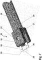
- FIG. 7 illustrates a perspective view of a connector for a hoisting rope of a hoisting apparatus according to one embodiment of the present invention.
- the connector 15 for a hoisting rope of a hoisting apparatus according to the presented embodiment comprises a top clamp part 16, a bottom clamp part 17 and a connector plate part 18.
- a hoisting rope 19 is placed between said top clamp part 16 and said bottom clamp part 17 so that a notch opening 20 in the end part of said hoisting rope 19 is in position with a tooth part of said top clamp part 16 and with a bended portion of said connector plate part 18.
- a fixing bolt 24 and a respective nut 25 are for tightening and consequently clamping said top clamp part 16 and said bottom clamp part 17 of said connector 15 onto said hoisting rope 19.
- FIG. 7 also illustrates a small piece 28 of sheet metal of said connector plate part 18 may be cut away to form two separate blade connectors 29, 30 of said connector 15.
- the connector 15 for a hoisting rope can now connected to a condition monitoring device 9.
- the connector 15 for a hoisting rope may forward information for quantifying the severity of the defect 14 such as e.g. fiber damage to said condition monitoring device 9.
- the connector 15 for a hoisting rope could be assumed as one obstacle for the user.
- the load bearing members 3-6 are substantially rectangular. However, this is not necessary as alternative shapes could be used. Said composite members 3-6 can be manufactured for example in any known way, such as in the manner presented in WO2009090299A1 .
- the rope 1 comprises four load bearing members 3-6.
- the arrangement is implemented with a rope provided with some other number of load bearing members 3-6.
- conductivity in this application it is meant electrical conductivity.
- a connection of good quality between load bearing members 3-6 of the hoisting rope and the condition monitoring device 9 can be secured.
- the condition monitoring device 9 can monitor the condition of the hoisting rope and notice if there is an indication of damage or an indication that the rope is going to brake.
- the connector solution according to the present invention With the help of the connector solution according to the present invention the on-site installation of the electrical connection is easier and faster than with the prior art solutions. Furthermore, the connector solution according to the present invention is reliable and withstands temperature changes considerably better than the prior art solutions.
Landscapes
- Lift-Guide Devices, And Elevator Ropes And Cables (AREA)
Priority Applications (1)
| Application Number | Priority Date | Filing Date | Title |
|---|---|---|---|
| EP16206745.8A EP3339231A1 (fr) | 2016-12-23 | 2016-12-23 | Connecteur pour câble de levage d'un appareil de levage |
Applications Claiming Priority (1)
| Application Number | Priority Date | Filing Date | Title |
|---|---|---|---|
| EP16206745.8A EP3339231A1 (fr) | 2016-12-23 | 2016-12-23 | Connecteur pour câble de levage d'un appareil de levage |
Publications (1)
| Publication Number | Publication Date |
|---|---|
| EP3339231A1 true EP3339231A1 (fr) | 2018-06-27 |
Family
ID=57681419
Family Applications (1)
| Application Number | Title | Priority Date | Filing Date |
|---|---|---|---|
| EP16206745.8A Withdrawn EP3339231A1 (fr) | 2016-12-23 | 2016-12-23 | Connecteur pour câble de levage d'un appareil de levage |
Country Status (1)
| Country | Link |
|---|---|
| EP (1) | EP3339231A1 (fr) |
Citations (3)
| Publication number | Priority date | Publication date | Assignee | Title |
|---|---|---|---|---|
| WO2009090299A1 (fr) | 2008-01-18 | 2009-07-23 | Kone Corporation | Câble pour machine de levage, ascenseur et utilisation |
| US20110220438A1 (en) * | 2008-11-19 | 2011-09-15 | Mirco Annen | Load supporting belt |
| US20120090924A1 (en) * | 2009-07-06 | 2012-04-19 | Arnold Odermatt | Contacting device |
-
2016
- 2016-12-23 EP EP16206745.8A patent/EP3339231A1/fr not_active Withdrawn
Patent Citations (3)
| Publication number | Priority date | Publication date | Assignee | Title |
|---|---|---|---|---|
| WO2009090299A1 (fr) | 2008-01-18 | 2009-07-23 | Kone Corporation | Câble pour machine de levage, ascenseur et utilisation |
| US20110220438A1 (en) * | 2008-11-19 | 2011-09-15 | Mirco Annen | Load supporting belt |
| US20120090924A1 (en) * | 2009-07-06 | 2012-04-19 | Arnold Odermatt | Contacting device |
Similar Documents
| Publication | Publication Date | Title |
|---|---|---|
| US11414301B2 (en) | Method and arrangement for condition monitoring of a hoisting rope of a hoisting apparatus | |
| EP3028979A1 (fr) | Procédé pour la production d'un dispositif de contact électrique et dispositif de contact électrique | |
| EP2466003B1 (fr) | Structure et procédé d'ancrage d'extrémité destiné à un corps filamentaire plastique renforcé par de la fibre | |
| US4509233A (en) | Rope clamp construction | |
| CN102056830B (zh) | 吊索端部固定装置 | |
| CN102770364B (zh) | 包括带与连接装置的组件及将连接装置安装到带上的方法 | |
| EP3163119A1 (fr) | Procédé, agencement de corde et ascenseur | |
| JP4869385B2 (ja) | ロープ式エレベーター | |
| JP5320527B2 (ja) | 高強度ケーブル | |
| US20160355378A1 (en) | Rope terminal arrangement and an elevator | |
| US20120034025A1 (en) | Cable Connection Systems and Methods | |
| US20180209060A1 (en) | Plated fiber, carbon fiber, wire harness and plating method | |
| US7819690B2 (en) | Electrical connector for piercing a conductive member | |
| CN220410346U (zh) | 锻造型无螺栓整体吊弦、接触线及承力索吊弦线夹 | |
| EP3339231A1 (fr) | Connecteur pour câble de levage d'un appareil de levage | |
| US4684293A (en) | Cable for fastening structures and method of detecting damage to corrosion-preventive layer thereof | |
| EP3348510A1 (fr) | Agencement de terminaison pour un câble d'un appareil de levage | |
| US12234126B2 (en) | Connection device and connection method for detection of a tension member for an elevator | |
| JP2024503163A (ja) | 引張歪みシースを備えている架空電気ケーブルの終端配列 | |
| CN221878557U (zh) | 一种用于预应力筋的锚固装置 | |
| US20150136445A1 (en) | Non-conductive wire splice connector | |
| CN217545494U (zh) | 一种聚苯醚护套数控设备连接线束 | |
| CN110998138B (zh) | 由结构中可静态负载组件组成的系统 | |
| HK1221448B (zh) | 用於提升绳索的状况监视的配置件及其制造方法 | |
| JP4475673B2 (ja) | ワイヤーソー接続用スリーブおよびワイヤーソー |
Legal Events
| Date | Code | Title | Description |
|---|---|---|---|
| PUAI | Public reference made under article 153(3) epc to a published international application that has entered the european phase |
Free format text: ORIGINAL CODE: 0009012 |
|
| AK | Designated contracting states |
Kind code of ref document: A1 Designated state(s): AL AT BE BG CH CY CZ DE DK EE ES FI FR GB GR HR HU IE IS IT LI LT LU LV MC MK MT NL NO PL PT RO RS SE SI SK SM TR |
|
| AX | Request for extension of the european patent |
Extension state: BA ME |
|
| STAA | Information on the status of an ep patent application or granted ep patent |
Free format text: STATUS: THE APPLICATION IS DEEMED TO BE WITHDRAWN |
|
| 18D | Application deemed to be withdrawn |
Effective date: 20190103 |