EP3339512B1 - Système de retenue de véhicule - Google Patents
Système de retenue de véhicule Download PDFInfo
- Publication number
- EP3339512B1 EP3339512B1 EP16205576.8A EP16205576A EP3339512B1 EP 3339512 B1 EP3339512 B1 EP 3339512B1 EP 16205576 A EP16205576 A EP 16205576A EP 3339512 B1 EP3339512 B1 EP 3339512B1
- Authority
- EP
- European Patent Office
- Prior art keywords
- support
- retention system
- post
- console
- vehicle retention
- Prior art date
- Legal status (The legal status is an assumption and is not a legal conclusion. Google has not performed a legal analysis and makes no representation as to the accuracy of the status listed.)
- Not-in-force
Links
Images



Classifications
-
- E—FIXED CONSTRUCTIONS
- E01—CONSTRUCTION OF ROADS, RAILWAYS, OR BRIDGES
- E01F—ADDITIONAL WORK, SUCH AS EQUIPPING ROADS OR THE CONSTRUCTION OF PLATFORMS, HELICOPTER LANDING STAGES, SIGNS, SNOW FENCES, OR THE LIKE
- E01F15/00—Safety arrangements for slowing, redirecting or stopping errant vehicles, e.g. guard posts or bollards; Arrangements for reducing damage to roadside structures due to vehicular impact
- E01F15/14—Safety arrangements for slowing, redirecting or stopping errant vehicles, e.g. guard posts or bollards; Arrangements for reducing damage to roadside structures due to vehicular impact specially adapted for local protection, e.g. for bridge piers, for traffic islands
- E01F15/143—Protecting devices located at the ends of barriers
Definitions
- the invention relates to a arranged next to a carriageway F vehicle restraint system, with at least one held on posts, extending in the direction of travel spar, and having a spar-shaped, designed as a lowering initial and / or final construction.
- Such a vehicle restraint system is for lowering from the EP 2 927 373 A1 known.
- the training is to broaden the surface of the lowering of an approaching vehicle and stabilize this.
- This known doctrine can not fulfill the required task, since a vehicle running up to the lowering is lifted on one side of the vehicle on the upper edge of the plank of the lowering and the other side impinges intermittently only on the support arms arranged at a distance from the posts and thus in each case between successive support arms behind the spar falls.
- Another such vehicle restraint system is also from the EP 2 927 374 A1 known.
- the invention is therefore based on the object of specifying a generic vehicle restraint system, in which a colliding vehicle with four wheels undergoes stable continuous support.
- the support structure is fixed at its end facing the road surface directly or indirectly on the spar, the distance between the individual support structures regardless of the distance of the posts arbitrarily smaller or larger than that can be designed. As a result, the stable determination of the further device can be ensured.
- console is a support profile which extends in the longitudinal direction of the roadway and is fastened to the post, and the support structure rests directly or indirectly on a bearing area on the bracket. As a result, a stable support is provided.
- the support profile is a rigid profile, a base is fixed to the post. As a result, the torsional moment is introduced into the post and received by the post.
- the support profile is arranged offset away from the roadway backwards below the spar.
- the torque acting on the spar is favorably influenced, ie reduced.
- the sliding or supporting device may be part of a guide system for at least one displaceable energy absorbing element.
- a guide system for at least one displaceable energy absorbing element.
- the guide system may be arranged on the support structure so that at least a portion of the head surface remains free to allow subsequent adjustment (turning) of the post.
- this is a wall frame structure, which is fixed by means of one of the roadway facing frame portion on the spar and is supported by a lower frame portion on the console.
- the support structure is fastened to the spar by means of a wall section formed at its road-side end with the interposition of such a support bracket, as is also used for fixing the spar to a post.
- Fig. 1 a arranged next to a roadway vehicle restraint system 1 is shown with a trained as a lowering 4 start and / or end construction.
- the vehicle restraint system 1 has an extending in the direction of travel FR, assembled from several individual pieces spar 3, which is held on post 2, and support structures 5, which have a predetermined distance from each other.
- the support structure 5 is used in the illustrated embodiment, the support of energy-absorbing elements 10, of which 12 are arranged one behind the other in the example shown. However, depending on the design, more or less energy-absorbing elements may be provided. These elements absorb the kinetic energy of a vehicle that has strayed off the lane and is traveling up to the downslope 4. By this arrangement, it can be prevented that such a vehicle on the lowering as on a ski jump performs a long flight.
- Fig. 2 shows in a perspective schematic view of part of a lowering 4 of the vehicle restraint system Fig.1 in which a spar 3 is held on posts 2. Furthermore, a console 6 is attached to the post 2. The bracket 6 may additionally be held by means of one or more retaining tabs 6 'on the spar 3.
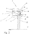
- Fig. 3 shows a view in the direction of travel on the vehicle restraint system 1 with support structure 5, spar 3, console 6 and sliding or support means 7.
- the support structure 5 is arranged so that it faces away from the carriageway F.
- Below the support structure 5 is at the back of the vehicle restraint system 1 to the post 2, a bracket 6 for supporting the support structure 5 arranged.
- the console 6 may be held on a stand-alone post assembly.
- the support structure 5 is provided with a support area 8 which rests on the console 6.
- the support structure 5 is located directly on the console 6; However, it may also be an intermediate layer between the bracket 6 and the support area 8 may be arranged, which largely prevents corrosion of the superimposed components.
- the arranged on the support structure 5, extending in the direction of travel slide or support means 7 can serve as a guideway for provided on the lowering traffic safety devices.
- this can be a form-locking guide which is formed by mutually opposite C-profiles, but a substantially planar guideway for safety devices is also possible.
- the bracket 6 is an L-shaped angle profile which extends in the longitudinal direction of the road F and is fastened below the beam 3 away from the roadway to the post and offset backwards.
- the sliding or supporting device 7 is in the illustrated example part of a mounting or guiding system for at least one displaceable energy absorbing element 10.
- a mounting or guiding system by one or more Guide rods / ropes can be ensured, which are guided through openings in the elements 10 (not shown).
- a leading over this post slide or support means 7 is offset laterally so far that a tool can be applied;
- the sliding or supporting device has a flat, plate-like shape. It may be provided at this point when using a plate web as a sliding or support means a recess.
- the support structure 5 is a wall frame structure 14.
- the stiffeners 15 shown in this example are not mandatory, but allow a stable and lightweight truss construction.
- the support structure 5 is fixed here by means of a roadway facing frame portion 16 on the spar 3 and supported by a lower frame portion 17 on the bracket 6.
- the spar 3 has on its side remote from the road on a support bracket 18 with an upper and a lower support wings 19 and a support wings both connecting abutting portion 20.
- the support structure 5 rests against the abutment portion 20 of the support bracket 18 of the beam 3 by means of a frame portion 16 formed at its roadside end and is fastened thereto.
- FIG. 4 shows a next embodiment of the support structure according to the invention 5.
- the support structure 5 a horizontally extending support arm 21 with a vertically downwardly projecting stop leg 22.
- a stiffener 23 is arranged in the angle between the support arm 21 and stop leg 22, wherein it has a lower peripheral edge, with which it rests on the console 6.
- a plate 24 may be provided to provide a wider support on the console 6.
- an additional reinforcement 25 may be arranged to increase the stability of the support structure 5.
- the support structure 5 is used in the illustrated embodiment, the inclusion of a rail assembly 25 in which the sliding or support means 7 is formed.
- traffic safety devices are added on the support structure 5 . These can be energy-consuming deformation bodies that deform plastically in the event of a collision of a vehicle and thereby convert the kinetic energy of the vehicle into deformation work.
- a support bracket 18 is also arranged in this embodiment, which rests with its abutment portion 20 on the stop leg 22 of the support structure 5 and is secured thereto.
- the invention is not limited in its execution to the above-mentioned preferred embodiments. Rather, a number of variants is conceivable, which makes use of the illustrated solution even with fundamentally different types of use.
Landscapes
- Engineering & Computer Science (AREA)
- Architecture (AREA)
- Civil Engineering (AREA)
- Structural Engineering (AREA)
- Refuge Islands, Traffic Blockers, Or Guard Fence (AREA)
Claims (8)
- Système de retenue de véhicule (1) disposé à côté d'une chaussée F, avec au moins un rail (3) maintenu par des poteaux (2) et s'étendant dans le sens de la marche (FR), et avec une structure de début ou de fin présentant ledit au moins un rail (3) et réalisée sous forme de renfoncement (4), caractérisé en ce qu'au moins au niveau du renfoncement (4)- au moins une structure de support (5) est directement ou indirectement fixée au rail (3) et détournée de la chaussée (F),dans lequel- une console (6) est disposée sur la face arrière du poteau (2) pour étayer la structure de support (5), et- avec au moins un dispositif de glissement ou d'appui (7) posé directement ou indirectement sur la structure de support (5) et s'étendant dans le sens de la marche.
- Système de retenue de véhicule selon la revendication 1, caractérisé en ce que la structure de support (5) repose directement ou indirectement sur la console dans une zone d'appui (8).
- Système de retenue de véhicule selon les revendications 1 ou 2, caractérisé en ce que la console (6) est un profilé support fixé aux poteaux (2) et s'étendant dans le sens longitudinal de la chaussée (F).
- Système de retenue de véhicule selon au moins l'une des revendications précédentes, caractérisé en ce que la console (6) est disposée au-dessous d'un rail (3) en retrait en s'éloignant de la chaussée (F).
- Système de retenue de véhicule selon au moins l'une des revendications précédentes, caractérisé en ce que le dispositif de glissement ou d'appui (7) fait partie d'un système de guidage (9) pour au moins un élément d'absorption d'énergie (10).
- Système de retenue de véhicule selon au moins l'une des revendications précédentes, caractérisé en ce que le dispositif de glissement ou d'appui (7) passant par la tête du poteau (2) est mis en retrait vers le côté du poteau (2) éloigné de la chaussée afin de dégager une partie de la surface de tête pour l'accès à une surface de tête (13) du poteau (2) et pour permettre l'accès.
- Système de retenue de véhicule selon au moins l'une des revendications précédentes, caractérisé en ce que la structure de support (5) est une structure (14) de paroi et cadre calée sur ledit au moins rail (3) au moyen d'une section de cadre (16) tournée vers la chaussée (F) et prenant appui sur la console (6) par une section de cadre (17) inférieure.
- Système de retenue de véhicule selon la revendication 1, caractérisé en ce que ledit rail (3) présente sur son côté éloigné de la chaussée un étrier support (18) avec une branche de support supérieure et une branche de support inférieure (19) et une section de butée (20) reliant les deux branches entre elles, ladite structure de support (5) venant en butée contre la section de butée (20) de l'étrier-support (18) du rail (3) au moyen de la section de paroi (16) réalisée à son extrémité côté chaussée et y est fixée.
Priority Applications (1)
| Application Number | Priority Date | Filing Date | Title |
|---|---|---|---|
| EP16205576.8A EP3339512B1 (fr) | 2016-12-20 | 2016-12-20 | Système de retenue de véhicule |
Applications Claiming Priority (1)
| Application Number | Priority Date | Filing Date | Title |
|---|---|---|---|
| EP16205576.8A EP3339512B1 (fr) | 2016-12-20 | 2016-12-20 | Système de retenue de véhicule |
Publications (2)
| Publication Number | Publication Date |
|---|---|
| EP3339512A1 EP3339512A1 (fr) | 2018-06-27 |
| EP3339512B1 true EP3339512B1 (fr) | 2019-04-24 |
Family
ID=57609724
Family Applications (1)
| Application Number | Title | Priority Date | Filing Date |
|---|---|---|---|
| EP16205576.8A Not-in-force EP3339512B1 (fr) | 2016-12-20 | 2016-12-20 | Système de retenue de véhicule |
Country Status (1)
| Country | Link |
|---|---|
| EP (1) | EP3339512B1 (fr) |
Families Citing this family (1)
| Publication number | Priority date | Publication date | Assignee | Title |
|---|---|---|---|---|
| EP4137638A1 (fr) * | 2021-08-20 | 2023-02-22 | voestalpine Krems Finaltechnik GmbH | Terminal pour un système de retenue de véhicule et système de retenue de véhicule correspondant |
Family Cites Families (4)
| Publication number | Priority date | Publication date | Assignee | Title |
|---|---|---|---|---|
| EP0761889B1 (fr) * | 1995-08-26 | 1999-02-10 | SPIG Schutzplanken-Produktions-Gesellschaft mbH & Co.KG | Disposition de barrière routière |
| DE102007033770B3 (de) * | 2007-07-18 | 2008-10-16 | Heintzmann Sicherheitssysteme Gmbh & Co. Kg | Schutzplankenanordnung |
| DE102014104667B4 (de) * | 2014-04-02 | 2019-04-18 | SGGT Straßenausstattungen GmbH | Fahrzeugrückhaltesystem mit Anfangs-/Endkonstruktion |
| DE102014104670A1 (de) * | 2014-04-02 | 2015-10-08 | SGGT Straßenausstattungen GmbH | Fahrzeugrückhaltesystem mit Anfangs-/Endkonstruktion |
-
2016
- 2016-12-20 EP EP16205576.8A patent/EP3339512B1/fr not_active Not-in-force
Non-Patent Citations (1)
| Title |
|---|
| None * |
Also Published As
| Publication number | Publication date |
|---|---|
| EP3339512A1 (fr) | 2018-06-27 |
Similar Documents
| Publication | Publication Date | Title |
|---|---|---|
| EP2730700B1 (fr) | Système de retenue de véhicule destiné à être agencé sur un ouvrage de pont | |
| DE3809470C2 (fr) | ||
| DE102007024993B4 (de) | Fahrzeug-Rückhaltesystem an Verkehrswegen | |
| EP3339512B1 (fr) | Système de retenue de véhicule | |
| DE19907954B4 (de) | Passive Schutzeinrichtung | |
| WO2002086242A1 (fr) | Ensemble terminal pour systemes de retenue en profiles d'acier disposes lateralement sur des arteres de communication | |
| DE102007063511B4 (de) | Schutzeinrichtung an Verkehrswegen | |
| DE2642475A1 (de) | Leitplanke | |
| DE202012013184U1 (de) | Terminal | |
| DE202010000658U1 (de) | Schutzplankenanordnung | |
| DE2413095C3 (de) | Leiteinrichtung fUr Personen- und Lastkraftwagen | |
| DE202016107194U1 (de) | Fahrzeugrückhaltesystem | |
| DE202008011203U1 (de) | Fahrzeugrückhaltesystem an Verkehrswegen | |
| EP2904153B1 (fr) | Système de retenue et structure de transition entre deux systèmes de retenue de véhicules présentant des rigidités latérales différentes | |
| EP1460181B1 (fr) | Dispositif de réception de chargements tombants d'un véhicule | |
| DE202005008391U1 (de) | Übergang bei Verkehrswegen von einer Betongleitwand auf eine Schutzplankenanordnung | |
| DE102014104667B4 (de) | Fahrzeugrückhaltesystem mit Anfangs-/Endkonstruktion | |
| DE102007033732A1 (de) | Schutzplankenanordnung | |
| EP1285999A2 (fr) | Glissière de sécurité | |
| AT512661B1 (de) | Fahrzeugrückhaltesystem | |
| EP2439340B1 (fr) | Système de barrière de sécurité | |
| CH693640A5 (de) | Passive Schutzeinrichtung für Fahrzeuge zur Anbringung neben einem Verkehrsweg. | |
| DE1534565C (de) | Leitplanke für Straßen | |
| DE202012013270U1 (de) | Gleitschieneneinrichtung für einen horizontalen Terminal | |
| AT524699A1 (de) | Leitwandelement |
Legal Events
| Date | Code | Title | Description |
|---|---|---|---|
| PUAI | Public reference made under article 153(3) epc to a published international application that has entered the european phase |
Free format text: ORIGINAL CODE: 0009012 |
|
| STAA | Information on the status of an ep patent application or granted ep patent |
Free format text: STATUS: THE APPLICATION HAS BEEN PUBLISHED |
|
| AK | Designated contracting states |
Kind code of ref document: A1 Designated state(s): AL AT BE BG CH CY CZ DE DK EE ES FI FR GB GR HR HU IE IS IT LI LT LU LV MC MK MT NL NO PL PT RO RS SE SI SK SM TR |
|
| AX | Request for extension of the european patent |
Extension state: BA ME |
|
| STAA | Information on the status of an ep patent application or granted ep patent |
Free format text: STATUS: REQUEST FOR EXAMINATION WAS MADE |
|
| 17P | Request for examination filed |
Effective date: 20180809 |
|
| RBV | Designated contracting states (corrected) |
Designated state(s): AL AT BE BG CH CY CZ DE DK EE ES FI FR GB GR HR HU IE IS IT LI LT LU LV MC MK MT NL NO PL PT RO RS SE SI SK SM TR |
|
| GRAP | Despatch of communication of intention to grant a patent |
Free format text: ORIGINAL CODE: EPIDOSNIGR1 |
|
| STAA | Information on the status of an ep patent application or granted ep patent |
Free format text: STATUS: GRANT OF PATENT IS INTENDED |
|
| INTG | Intention to grant announced |
Effective date: 20181031 |
|
| GRAS | Grant fee paid |
Free format text: ORIGINAL CODE: EPIDOSNIGR3 |
|
| GRAA | (expected) grant |
Free format text: ORIGINAL CODE: 0009210 |
|
| STAA | Information on the status of an ep patent application or granted ep patent |
Free format text: STATUS: THE PATENT HAS BEEN GRANTED |
|
| AK | Designated contracting states |
Kind code of ref document: B1 Designated state(s): AL AT BE BG CH CY CZ DE DK EE ES FI FR GB GR HR HU IE IS IT LI LT LU LV MC MK MT NL NO PL PT RO RS SE SI SK SM TR |
|
| REG | Reference to a national code |
Ref country code: GB Ref legal event code: FG4D Free format text: NOT ENGLISH |
|
| REG | Reference to a national code |
Ref country code: CH Ref legal event code: EP |
|
| REG | Reference to a national code |
Ref country code: AT Ref legal event code: REF Ref document number: 1124313 Country of ref document: AT Kind code of ref document: T Effective date: 20190515 Ref country code: IE Ref legal event code: FG4D Free format text: LANGUAGE OF EP DOCUMENT: GERMAN |
|
| REG | Reference to a national code |
Ref country code: DE Ref legal event code: R096 Ref document number: 502016004315 Country of ref document: DE |
|
| REG | Reference to a national code |
Ref country code: NL Ref legal event code: MP Effective date: 20190424 |
|
| REG | Reference to a national code |
Ref country code: LT Ref legal event code: MG4D |
|
| PG25 | Lapsed in a contracting state [announced via postgrant information from national office to epo] |
Ref country code: NL Free format text: LAPSE BECAUSE OF FAILURE TO SUBMIT A TRANSLATION OF THE DESCRIPTION OR TO PAY THE FEE WITHIN THE PRESCRIBED TIME-LIMIT Effective date: 20190424 |
|
| PG25 | Lapsed in a contracting state [announced via postgrant information from national office to epo] |
Ref country code: FI Free format text: LAPSE BECAUSE OF FAILURE TO SUBMIT A TRANSLATION OF THE DESCRIPTION OR TO PAY THE FEE WITHIN THE PRESCRIBED TIME-LIMIT Effective date: 20190424 Ref country code: NO Free format text: LAPSE BECAUSE OF FAILURE TO SUBMIT A TRANSLATION OF THE DESCRIPTION OR TO PAY THE FEE WITHIN THE PRESCRIBED TIME-LIMIT Effective date: 20190724 Ref country code: HR Free format text: LAPSE BECAUSE OF FAILURE TO SUBMIT A TRANSLATION OF THE DESCRIPTION OR TO PAY THE FEE WITHIN THE PRESCRIBED TIME-LIMIT Effective date: 20190424 Ref country code: AL Free format text: LAPSE BECAUSE OF FAILURE TO SUBMIT A TRANSLATION OF THE DESCRIPTION OR TO PAY THE FEE WITHIN THE PRESCRIBED TIME-LIMIT Effective date: 20190424 Ref country code: SE Free format text: LAPSE BECAUSE OF FAILURE TO SUBMIT A TRANSLATION OF THE DESCRIPTION OR TO PAY THE FEE WITHIN THE PRESCRIBED TIME-LIMIT Effective date: 20190424 Ref country code: ES Free format text: LAPSE BECAUSE OF FAILURE TO SUBMIT A TRANSLATION OF THE DESCRIPTION OR TO PAY THE FEE WITHIN THE PRESCRIBED TIME-LIMIT Effective date: 20190424 Ref country code: PT Free format text: LAPSE BECAUSE OF FAILURE TO SUBMIT A TRANSLATION OF THE DESCRIPTION OR TO PAY THE FEE WITHIN THE PRESCRIBED TIME-LIMIT Effective date: 20190824 Ref country code: LT Free format text: LAPSE BECAUSE OF FAILURE TO SUBMIT A TRANSLATION OF THE DESCRIPTION OR TO PAY THE FEE WITHIN THE PRESCRIBED TIME-LIMIT Effective date: 20190424 |
|
| PG25 | Lapsed in a contracting state [announced via postgrant information from national office to epo] |
Ref country code: BG Free format text: LAPSE BECAUSE OF FAILURE TO SUBMIT A TRANSLATION OF THE DESCRIPTION OR TO PAY THE FEE WITHIN THE PRESCRIBED TIME-LIMIT Effective date: 20190724 Ref country code: PL Free format text: LAPSE BECAUSE OF FAILURE TO SUBMIT A TRANSLATION OF THE DESCRIPTION OR TO PAY THE FEE WITHIN THE PRESCRIBED TIME-LIMIT Effective date: 20190424 Ref country code: RS Free format text: LAPSE BECAUSE OF FAILURE TO SUBMIT A TRANSLATION OF THE DESCRIPTION OR TO PAY THE FEE WITHIN THE PRESCRIBED TIME-LIMIT Effective date: 20190424 Ref country code: LV Free format text: LAPSE BECAUSE OF FAILURE TO SUBMIT A TRANSLATION OF THE DESCRIPTION OR TO PAY THE FEE WITHIN THE PRESCRIBED TIME-LIMIT Effective date: 20190424 Ref country code: GR Free format text: LAPSE BECAUSE OF FAILURE TO SUBMIT A TRANSLATION OF THE DESCRIPTION OR TO PAY THE FEE WITHIN THE PRESCRIBED TIME-LIMIT Effective date: 20190725 |
|
| PG25 | Lapsed in a contracting state [announced via postgrant information from national office to epo] |
Ref country code: IS Free format text: LAPSE BECAUSE OF FAILURE TO SUBMIT A TRANSLATION OF THE DESCRIPTION OR TO PAY THE FEE WITHIN THE PRESCRIBED TIME-LIMIT Effective date: 20190824 |
|
| REG | Reference to a national code |
Ref country code: DE Ref legal event code: R097 Ref document number: 502016004315 Country of ref document: DE |
|
| PG25 | Lapsed in a contracting state [announced via postgrant information from national office to epo] |
Ref country code: CZ Free format text: LAPSE BECAUSE OF FAILURE TO SUBMIT A TRANSLATION OF THE DESCRIPTION OR TO PAY THE FEE WITHIN THE PRESCRIBED TIME-LIMIT Effective date: 20190424 Ref country code: RO Free format text: LAPSE BECAUSE OF FAILURE TO SUBMIT A TRANSLATION OF THE DESCRIPTION OR TO PAY THE FEE WITHIN THE PRESCRIBED TIME-LIMIT Effective date: 20190424 Ref country code: SK Free format text: LAPSE BECAUSE OF FAILURE TO SUBMIT A TRANSLATION OF THE DESCRIPTION OR TO PAY THE FEE WITHIN THE PRESCRIBED TIME-LIMIT Effective date: 20190424 Ref country code: EE Free format text: LAPSE BECAUSE OF FAILURE TO SUBMIT A TRANSLATION OF THE DESCRIPTION OR TO PAY THE FEE WITHIN THE PRESCRIBED TIME-LIMIT Effective date: 20190424 Ref country code: DK Free format text: LAPSE BECAUSE OF FAILURE TO SUBMIT A TRANSLATION OF THE DESCRIPTION OR TO PAY THE FEE WITHIN THE PRESCRIBED TIME-LIMIT Effective date: 20190424 |
|
| PG25 | Lapsed in a contracting state [announced via postgrant information from national office to epo] |
Ref country code: SM Free format text: LAPSE BECAUSE OF FAILURE TO SUBMIT A TRANSLATION OF THE DESCRIPTION OR TO PAY THE FEE WITHIN THE PRESCRIBED TIME-LIMIT Effective date: 20190424 Ref country code: IT Free format text: LAPSE BECAUSE OF FAILURE TO SUBMIT A TRANSLATION OF THE DESCRIPTION OR TO PAY THE FEE WITHIN THE PRESCRIBED TIME-LIMIT Effective date: 20190424 |
|
| PLBE | No opposition filed within time limit |
Free format text: ORIGINAL CODE: 0009261 |
|
| STAA | Information on the status of an ep patent application or granted ep patent |
Free format text: STATUS: NO OPPOSITION FILED WITHIN TIME LIMIT |
|
| PG25 | Lapsed in a contracting state [announced via postgrant information from national office to epo] |
Ref country code: TR Free format text: LAPSE BECAUSE OF FAILURE TO SUBMIT A TRANSLATION OF THE DESCRIPTION OR TO PAY THE FEE WITHIN THE PRESCRIBED TIME-LIMIT Effective date: 20190424 |
|
| 26N | No opposition filed |
Effective date: 20200127 |
|
| PG25 | Lapsed in a contracting state [announced via postgrant information from national office to epo] |
Ref country code: SI Free format text: LAPSE BECAUSE OF FAILURE TO SUBMIT A TRANSLATION OF THE DESCRIPTION OR TO PAY THE FEE WITHIN THE PRESCRIBED TIME-LIMIT Effective date: 20190424 |
|
| REG | Reference to a national code |
Ref country code: CH Ref legal event code: PL |
|
| REG | Reference to a national code |
Ref country code: BE Ref legal event code: MM Effective date: 20191231 |
|
| PG25 | Lapsed in a contracting state [announced via postgrant information from national office to epo] |
Ref country code: MC Free format text: LAPSE BECAUSE OF FAILURE TO SUBMIT A TRANSLATION OF THE DESCRIPTION OR TO PAY THE FEE WITHIN THE PRESCRIBED TIME-LIMIT Effective date: 20190424 |
|
| PG25 | Lapsed in a contracting state [announced via postgrant information from national office to epo] |
Ref country code: LU Free format text: LAPSE BECAUSE OF NON-PAYMENT OF DUE FEES Effective date: 20191220 Ref country code: IE Free format text: LAPSE BECAUSE OF NON-PAYMENT OF DUE FEES Effective date: 20191220 |
|
| PG25 | Lapsed in a contracting state [announced via postgrant information from national office to epo] |
Ref country code: BE Free format text: LAPSE BECAUSE OF NON-PAYMENT OF DUE FEES Effective date: 20191231 Ref country code: LI Free format text: LAPSE BECAUSE OF NON-PAYMENT OF DUE FEES Effective date: 20191231 Ref country code: CH Free format text: LAPSE BECAUSE OF NON-PAYMENT OF DUE FEES Effective date: 20191231 |
|
| PGFP | Annual fee paid to national office [announced via postgrant information from national office to epo] |
Ref country code: FR Payment date: 20201223 Year of fee payment: 5 |
|
| PG25 | Lapsed in a contracting state [announced via postgrant information from national office to epo] |
Ref country code: CY Free format text: LAPSE BECAUSE OF FAILURE TO SUBMIT A TRANSLATION OF THE DESCRIPTION OR TO PAY THE FEE WITHIN THE PRESCRIBED TIME-LIMIT Effective date: 20190424 |
|
| PGFP | Annual fee paid to national office [announced via postgrant information from national office to epo] |
Ref country code: DE Payment date: 20210224 Year of fee payment: 5 |
|
| PG25 | Lapsed in a contracting state [announced via postgrant information from national office to epo] |
Ref country code: MT Free format text: LAPSE BECAUSE OF FAILURE TO SUBMIT A TRANSLATION OF THE DESCRIPTION OR TO PAY THE FEE WITHIN THE PRESCRIBED TIME-LIMIT Effective date: 20190424 Ref country code: HU Free format text: LAPSE BECAUSE OF FAILURE TO SUBMIT A TRANSLATION OF THE DESCRIPTION OR TO PAY THE FEE WITHIN THE PRESCRIBED TIME-LIMIT; INVALID AB INITIO Effective date: 20161220 |
|
| PG25 | Lapsed in a contracting state [announced via postgrant information from national office to epo] |
Ref country code: MK Free format text: LAPSE BECAUSE OF FAILURE TO SUBMIT A TRANSLATION OF THE DESCRIPTION OR TO PAY THE FEE WITHIN THE PRESCRIBED TIME-LIMIT Effective date: 20190424 |
|
| REG | Reference to a national code |
Ref country code: DE Ref legal event code: R119 Ref document number: 502016004315 Country of ref document: DE |
|
| PG25 | Lapsed in a contracting state [announced via postgrant information from national office to epo] |
Ref country code: DE Free format text: LAPSE BECAUSE OF NON-PAYMENT OF DUE FEES Effective date: 20220701 |
|
| PG25 | Lapsed in a contracting state [announced via postgrant information from national office to epo] |
Ref country code: FR Free format text: LAPSE BECAUSE OF NON-PAYMENT OF DUE FEES Effective date: 20211231 |
|
| PGFP | Annual fee paid to national office [announced via postgrant information from national office to epo] |
Ref country code: GB Payment date: 20221223 Year of fee payment: 7 |
|
| REG | Reference to a national code |
Ref country code: AT Ref legal event code: MM01 Ref document number: 1124313 Country of ref document: AT Kind code of ref document: T Effective date: 20211220 |
|
| PG25 | Lapsed in a contracting state [announced via postgrant information from national office to epo] |
Ref country code: AT Free format text: LAPSE BECAUSE OF NON-PAYMENT OF DUE FEES Effective date: 20211220 |
|
| GBPC | Gb: european patent ceased through non-payment of renewal fee |
Effective date: 20231220 |
|
| PG25 | Lapsed in a contracting state [announced via postgrant information from national office to epo] |
Ref country code: GB Free format text: LAPSE BECAUSE OF NON-PAYMENT OF DUE FEES Effective date: 20231220 |
|
| PG25 | Lapsed in a contracting state [announced via postgrant information from national office to epo] |
Ref country code: GB Free format text: LAPSE BECAUSE OF NON-PAYMENT OF DUE FEES Effective date: 20231220 |