EP3339558A1 - Dispositif de précontrainte de ressort pour rouleau de store - Google Patents
Dispositif de précontrainte de ressort pour rouleau de store Download PDFInfo
- Publication number
- EP3339558A1 EP3339558A1 EP17203443.1A EP17203443A EP3339558A1 EP 3339558 A1 EP3339558 A1 EP 3339558A1 EP 17203443 A EP17203443 A EP 17203443A EP 3339558 A1 EP3339558 A1 EP 3339558A1
- Authority
- EP
- European Patent Office
- Prior art keywords
- restraining
- spring
- rotation shaft
- protrusion
- tensioning device
- Prior art date
- Legal status (The legal status is an assumption and is not a legal conclusion. Google has not performed a legal analysis and makes no representation as to the accuracy of the status listed.)
- Granted
Links
Images





Classifications
-
- E—FIXED CONSTRUCTIONS
- E06—DOORS, WINDOWS, SHUTTERS, OR ROLLER BLINDS IN GENERAL; LADDERS
- E06B—FIXED OR MOVABLE CLOSURES FOR OPENINGS IN BUILDINGS, VEHICLES, FENCES OR LIKE ENCLOSURES IN GENERAL, e.g. DOORS, WINDOWS, BLINDS, GATES
- E06B9/00—Screening or protective devices for wall or similar openings, with or without operating or securing mechanisms; Closures of similar construction
- E06B9/24—Screens or other constructions affording protection against light, especially against sunshine; Similar screens for privacy or appearance; Slat blinds
- E06B9/26—Lamellar or like blinds, e.g. venetian blinds
- E06B9/28—Lamellar or like blinds, e.g. venetian blinds with horizontal lamellae, e.g. non-liftable
- E06B9/30—Lamellar or like blinds, e.g. venetian blinds with horizontal lamellae, e.g. non-liftable liftable
- E06B9/32—Operating, guiding, or securing devices therefor
- E06B9/322—Details of operating devices, e.g. pulleys, brakes, spring drums, drives
-
- E—FIXED CONSTRUCTIONS
- E06—DOORS, WINDOWS, SHUTTERS, OR ROLLER BLINDS IN GENERAL; LADDERS
- E06B—FIXED OR MOVABLE CLOSURES FOR OPENINGS IN BUILDINGS, VEHICLES, FENCES OR LIKE ENCLOSURES IN GENERAL, e.g. DOORS, WINDOWS, BLINDS, GATES
- E06B9/00—Screening or protective devices for wall or similar openings, with or without operating or securing mechanisms; Closures of similar construction
- E06B9/24—Screens or other constructions affording protection against light, especially against sunshine; Similar screens for privacy or appearance; Slat blinds
- E06B9/40—Roller blinds
- E06B9/42—Parts or details of roller blinds, e.g. suspension devices, blind boxes
-
- E—FIXED CONSTRUCTIONS
- E06—DOORS, WINDOWS, SHUTTERS, OR ROLLER BLINDS IN GENERAL; LADDERS
- E06B—FIXED OR MOVABLE CLOSURES FOR OPENINGS IN BUILDINGS, VEHICLES, FENCES OR LIKE ENCLOSURES IN GENERAL, e.g. DOORS, WINDOWS, BLINDS, GATES
- E06B9/00—Screening or protective devices for wall or similar openings, with or without operating or securing mechanisms; Closures of similar construction
- E06B9/24—Screens or other constructions affording protection against light, especially against sunshine; Similar screens for privacy or appearance; Slat blinds
- E06B9/26—Lamellar or like blinds, e.g. venetian blinds
- E06B9/38—Other details
-
- E—FIXED CONSTRUCTIONS
- E06—DOORS, WINDOWS, SHUTTERS, OR ROLLER BLINDS IN GENERAL; LADDERS
- E06B—FIXED OR MOVABLE CLOSURES FOR OPENINGS IN BUILDINGS, VEHICLES, FENCES OR LIKE ENCLOSURES IN GENERAL, e.g. DOORS, WINDOWS, BLINDS, GATES
- E06B9/00—Screening or protective devices for wall or similar openings, with or without operating or securing mechanisms; Closures of similar construction
- E06B9/24—Screens or other constructions affording protection against light, especially against sunshine; Similar screens for privacy or appearance; Slat blinds
- E06B9/40—Roller blinds
- E06B9/42—Parts or details of roller blinds, e.g. suspension devices, blind boxes
- E06B9/50—Bearings specially adapted therefor
-
- E—FIXED CONSTRUCTIONS
- E06—DOORS, WINDOWS, SHUTTERS, OR ROLLER BLINDS IN GENERAL; LADDERS
- E06B—FIXED OR MOVABLE CLOSURES FOR OPENINGS IN BUILDINGS, VEHICLES, FENCES OR LIKE ENCLOSURES IN GENERAL, e.g. DOORS, WINDOWS, BLINDS, GATES
- E06B9/00—Screening or protective devices for wall or similar openings, with or without operating or securing mechanisms; Closures of similar construction
- E06B9/56—Operating, guiding or securing devices or arrangements for roll-type closures; Spring drums; Tape drums; Counterweighting arrangements therefor
- E06B9/60—Spring drums operated only by closure members
-
- E—FIXED CONSTRUCTIONS
- E06—DOORS, WINDOWS, SHUTTERS, OR ROLLER BLINDS IN GENERAL; LADDERS
- E06B—FIXED OR MOVABLE CLOSURES FOR OPENINGS IN BUILDINGS, VEHICLES, FENCES OR LIKE ENCLOSURES IN GENERAL, e.g. DOORS, WINDOWS, BLINDS, GATES
- E06B9/00—Screening or protective devices for wall or similar openings, with or without operating or securing mechanisms; Closures of similar construction
- E06B9/56—Operating, guiding or securing devices or arrangements for roll-type closures; Spring drums; Tape drums; Counterweighting arrangements therefor
- E06B9/80—Safety measures against dropping or unauthorised opening; Braking or immobilising devices; Devices for limiting unrolling
Definitions
- the present invention generally relates to a spring pre-tensioning device for a roll blind. More particularly, the present invention relates to a spring pre-tensioning device for a roll blind, the pre-tensioning device configured such that a predetermined tension value of the spring is restrained to be constant through a predetermined number of rotations, whereby a precise tension value is applied to the roll blind such that a screen moves up and down smoothly.
- the pre-tensioning device has the following advantages: it has a very high economic value since it can be applied to any blind that is provided with a spring; it does not require adjustment of tension of the spring according to a size or a weight of roll screen fabric since it is pretensioned when manufactured; and it is configured to allow a blind to be easily attached to an detached from a bracket via a new bracket structure.
- a roll screen blind is used instead of a curtain at home, in an office, or in a restaurant, and is configured such that a screen is made of textile or synthetic resin, and when a ball chain of a sprocket provided in a bracket is pulled down in one direction, the screen rolled around a rotating tube is unrolled by tension of a spring, thereby blocking light coming through the window.
- a roll blind 20 is provided with a rotating body 10 on a front surface of each bracket 9.
- One rotating body 10 is provided with a rotating member 2 on a front surface thereof, and a back surface thereof is provided with a rotating unit that is fixedly provided with a connection shaft 3 having a spring 4.
- the rotating member 2 moves left and right along the connection shaft 3 by elastic force of the spring 4.
- the other rotating body 10 is provided with a reduction unit that is provided with a fixed shaft 7 having a reduction nut 7a in front of a reducer 6.
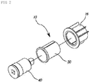
- the rotating body 10 is configured such that an outer surface of a rotating tube with the screen being rolled therearound is fitted under the cover 16 by inserting the rotating tube 30 into the cover. Further, an inside of the rotating tube 30 is coupled to a rotation shaft 40 with the spring being provided on an outer surface thereof, and is fixed using a washer.
- the rotating tube is fitted over the outer surface of each rotating body 10 that the screen is rolled around, and a bracket is locked to a window frame or a door frame to use the blind.
- a conventional blind is problematic in that in order to keep an initial state of the spring and a state where tension is applied to the spring, a head rail is required, whereby manufacturing cost may be increased.
- the conventional blind is further problematic in that since tension of the rotation shaft provided inside the rotating body may be loosen during transport or installation, a customer adjusts the tension him or herself, and thus returns may increase if the customer fails to adjust the tension.
- the safety pin apparatus in which a roll screen blind includes a rotating tube provided with a rotation shaft that is rotated by tension of a spring; the rotating tube inserted inside a cover, which a winding tube with a screen being rolled around an outer circumferential surface thereof is coupled to, such that the rotating tube, along with a rotating body, is rotated by a rotation of the rotation shaft, and the screen is moved up and down
- the safety pin apparatus includes: a rotation shaft 110 provided with a plurality of annular insertion holes 111 on an outer circumferential surface of a rear end thereof; and a rotating tube 120 inserted into the rotation shaft 110, and provided with a plurality of coupling holes 121 through an outer circumferential surface of a rear end thereof, wherein the rotation shaft 110 is inserted into the rotating tube 120, such that the insertion holes 111 of the rotation shaft 110 and the coupling holes 121 of the rotating tube 120 are aligned with each other, and a safety pin 130 having a handle 131 is engaged with the
- the above mentioned apparatus is problematic in that since the safety pin is exposed outside, it may fall out by an external force during transport, whereby tension of the spring may be loosened.
- the apparatus for attaching and detaching a roll screen includes: a carriage 20 configured such that a front portion thereof is provided with a washer groove 21, a back portion thereof is provided with a coupling member 22, a center of an outer surface thereof is formed with a locking plate 23, and a portion of the outer surface thereof is provided with an oblong coupling protrusion 24; an elastic spring 30 provided in front of the carriage 20, and coupled to come into close contact with the locking plate 23; a cover 40 inserted into the front portion of the carriage 20, and including an insertion hole 41 provided therein, with a coupling groove 42 formed in a front surface thereof, a guide hole 43 provided at each opposite side to correspond to each other, and a coupling plate 45 with a coupling holes 44; and a rotating member 50 coupled to the back of the carriage 20 to be coupled to the cover 40, and including an insertion member 52 with a guide groove 51 being at a predetermined angle formed on an outer circumferential surface thereof, and a handle 54 formed with a protru
- the present invention has been made keeping in mind the above problems occurring in the related art, and the present invention is intended to propose a spring pre-tensioning device for a roll blind, the device configured such that a predetermined tension value of the spring is restrained to be constant through a predetermined number of rotations, whereby the tension of the spring is not required to be adjusted by a manufacturer in mass production, and it is possible to prevent tension from being loosened during transport or installation.
- the present invention is further intended to propose a spring pre-tensioning device for a roll blind, the device configured such that a precise tension value is applied to the roll blind such that a screen moves up and down smoothly, and only by providing a pretensioned spring, the device can be applied to a roll screen without fault, whereby it is possible to increase economic value and reduce manufacturing cost.
- the present invention is further intended to propose a spring pre-tensioning device for a roll blind, the device configured such that a bracket is configured to be separated into a body and a coupling member, thereby facilitating installation of a blind.
- a spring pre-tensioning device for a roll blind, the pre-tensioning device including: a rotation shaft including a threaded part having a predetermined length provided on an outer circumferential surface of a first side thereof, with a restraining protrusion provided on the threaded part, and a locking groove provided at an end of a second side thereof; a restraining nut engaged with the threaded part of the rotation shaft, and disposed on the restraining protrusion provided at an end of the threaded part, so as to prevent the restraining nut from moving further forward; a restraining body provided with a shaft insertion hole therein, and provided with a locking protrusion and a locking clip on an outer circumferential surface thereof for allowing a spring to be connected and locked thereto; and the spring configured such that a first end thereof is locked by the locking protrusion of the restraining body, and a second end thereof is
- the spring pre-tensioning device is advantageous in that a predetermined tension value of the spring is restrained to be constant through a predetermined number of rotations, whereby a precise tension value is applied to the roll blind such that a screen moves up and down smoothly.
- the spring pre-tensioning device is further advantageous in that it can be applied to any blind that is provided with a spring, and thus the spring pre-tensioning device has a very high economic value, and tension of the spring is not need to be adjusted by a customer or a manufacturer, whereby it is possible to reduce manufacturing cost.
- the spring pre-tensioning device is further advantageous in that it is possible to easily attach and detach a blind through a bracket that is configured to be separated into a body and a coupling member.
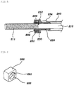
- FIG. 5 is a sectional view showing an entire configuration of the present invention
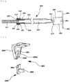
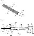
- FIGS. 6 to 10 are views showing a configuration of each component of the present invention
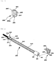
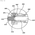
- FIGS. 11 to 13 are views showing another configuration of the present invention
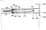
- FIGS. 14 to 15 are sectional views showing an installation state of the present invention.
- Reference numeral 200 refers to a spring pre-tensioning device for a roll blind of the present invention.
- the spring pre-tensioning device 200 for a roll blind includes: a rotation shaft 210 including a threaded part 211 provided with a restraining protrusion 212, and a locking groove 213; a restraining nut 220 disposed at the restraining protrusion 212 provided at an end of the threaded part 211 of the rotation shaft 210, so as not to move further forward; the restraining body 230 that is fitted over the outer circumferential surface of the rotation shaft 210 and is fixedly connected to the spring 240 is rotated to apply a predetermined pretension value to the spring 240, and is engaged with an outer surface of the restraining nut 220, thereby restraining pretension of the spring 240.
- the rotation shaft 210 includes: the threaded part 211 having a predetermined length provided on an outer circumferential surface of a first side of the rotation shaft, with the restraining protrusion 212 provided on the threaded part; the locking groove 213 provided at an end of a second side thereof so as to allow a stop protrusion of the spring 240 to be locked thereinto.
- the restraining nut 220 is formed into a quadrangular body, and is provided with an insertion hole 222 through the restraining nut, with threads 221 being formed on the inner surface thereof.
- a back surface of the restraining body 230 is provided with a nut insertion hole 231 having a quadrangular inner space, and the restraining body is provided with a locking clip 232 at each of opposite sides thereof.
- a front surface of the restraining body is provided with a shaft insertion hole 233, and an outer surface thereof is provided with a locking protrusion 234 and a pin insertion hole 235 for allowing the spring 240 to be connected and locked thereto.
- the spring 240 is configured such that a first end thereof is fixedly mounted at the locking protrusion 234 of the restraining body 230, and a second end thereof is engaged with the locking groove 213 of the rotation shaft 210.
- the threads 221 of the restraining nut 220 are engaged with the threaded part 211 of the rotation shaft 210, and are rotated to be disposed in the restraining protrusion 212 that is provided at the end of the threaded part 211, so as not to move further forward.
- the restraining body 230 that is connected to the first end of the spring 240 is rotated a predetermined number of times relative to the outer circumferential surface of the rotation shaft 210, thereby applying a tension value in advance.
- a pretension value may be adjustable according to a size of a roll blind or a length of roll screen fabric.
- the locking clip 232 of the restraining body 230 is engaged with the outer surface of the restraining nut 220, whereby the tension value of the spring 240 is restrained to be constant.
- a piece is mounted at an outside of an outer surface of the restraining body 230 so as to lock the restraining nut 220, such that the restraining body 230 is prevented from being separated from the restraining nut 220.
- the end of the threaded part 211 of the rotation shaft 210 is not provided with the restraining protrusion 212, such that the restraining nut 220 engaged with the threaded part 211 is prevented from moving forward over a portion that is not provided with threads.
- the locking groove 213 of the rotation shaft 210 is engaged with a rotating member 250 that is provided with a quadrangular coupling groove 251 on a back surface thereof; a rotating tube 252 is rotatably provided on an outer surface of the rotating member 250; and a roll screen having a predetermined length is rolled around an outer circumferential surface of the rotating tube 252.
- a bracket 260 is fixedly engaged with the coupling groove 251 of the rotating member 250; and as shown in FIGS. 9 and 10 , the bracket 260 includes a body 263, and coupling member 269 that is detachable from the body 263.
- the body 263 is configured such that a lower portion thereof and a center of a front surface thereof are open, a guide groove 261 is provided at each of opposite sides thereof being spaced at a predetermined interval, and a surface thereof is provided with a slit 262a that is in a C shape and is provided with a stop groove 262 at a lower portion of the body.
- the coupling member 269 is protrudingly provided with a guide protrusion 264 with a predetermined thickness on a front surface thereof and is provided with a coupling protrusion 265 protruding outwardly under the guide protrusion.
- an oblong groove 269a is provided at a center of a back surface of the coupling member, and an elastic stopper 267 that includes an inclined surface 266 and a separation pin 268 protruding downward provided respectively at an upper portion and a lower portion thereof is provided above the groove.
- the guide protrusion 264 is engaged with the guide groove 261 of the body 263 and is pushed up, whereby the elastic stopper 267 at the back is engaged with the slit 262a while going up, and at the same time, a lower portion of the elastic stopper 267 comes into close contact with and is locked to an upper portion of the stop groove 262.
- the separation pin 268 is engaged with the stop groove 262, and a lower portion thereof is exposed outside of the body 263.
- a spring pre-tensioning device for a roll blind includes: a rotation shaft 210 including a screw 214 provided with a restraining protrusion 212, and a locking groove 213; a restraining body 230 provided with a shaft insertion hole 233 therein, and provided with a locking protrusion 234 and a pin insertion hole 235 on an outer circumferential surface thereof for allowing a spring to be connected and locked thereto; and the spring 240 configured such that a first end thereof is locked by the locking protrusion 234 of the restraining body 230, and a second end thereof is coupled to the locking groove 213 of the rotation shaft 210, wherein the shaft insertion hole 233 of the restraining body 230 is fitted over the outer circumferential surface of the rotation shaft 210; the restraining body 230 is rotated to apply tension to the spring 240; and after the restraining protrusion 212 provided at an end of the screw 214, and the pin insertion
- the outer circumferential surface of the first side of the rotation shaft 210 is provided with the screw 214 having the roots 215 that are spaced apart from each other at predetermined intervals, and the end of the screw 214 is provided with the restraining protrusion 212 having a predetermined height.
- the restraining body 230 is provided with the shaft insertion hole 233 in a front surface thereof, and the locking protrusion 234 and the pin insertion hole 235 are provided in the outer surface of the restraining body for allowing the spring 240 to be connected and locked thereto.
- the spring 240 is configured such that a first end thereof is locked by the locking protrusion 234 of the restraining body (230), and a second end thereof is coupled to the locking groove 213 of the rotation shaft 210.
- the restraining body 230 is rotated a predetermined number of times to apply a tension value.
- the restraining body 230 is disposed in the restraining protrusion 212 provided at the end of the screw 214, and the locking member 270 having a locking pin 271 protruding outwardly is engaged with the pin insertion hole 235 of the restraining body 230, thereby being locked to the roots 215 of the screw 214.
- the locking pin 271 of the locking member 270 restrains the tension of the spring 240 that is pretensioned, in such a way that the locking pin restrains a direction where the spring is restored.
- a rotating member 250 is engaged with the locking groove 213 of the rotation shaft 210, and the rotating member 250 is coupled to a bracket 260 in the same way as the above mentioned manner.
- a tension value that corresponds to a size of a roll blind or a length of roll screen fabric is applied in advance, wherein firstly, the restraining nut 220 is engaged with the threaded part 211 of the rotation shaft 210 and is rotated to reach the restraining protrusion 212, so as not to move further forward.
- the locking clip 232 is locked to the outer surface of the restraining nut 220 restrained by the rotation shaft 210.
- spring 240 is restrained in a state where the tension value is applied, whereby the roll blind can be stopped at the same position.
- the restraining body 230 engaged with the screw 214 of the rotation shaft 210 is rotated a predetermined number of times to adjust tension, thereby applying the tension value.
- the restraining body 230 is disposed in the restraining protrusion 212 provided at the end of the screw 214, and the locking pin 271 of the locking member 270 is engaged with the roots 215 of the screw 214, thereby restraining the restraining body 230.
- the locking pin 271 of the locking member 270 serves to stop the blind to have a predetermined tension value of the spring.
- the present invention in which the spring 240 is applied the tension value as described above, is locked to opposite sides of a top surface of a window frame or a door frame by using the bracket 260, without a head rail.
- the rotating tube 252 which the roll screen is rolled around, is mounted to the outer surface of the rotating member 250, and at opposite location of the rotating tube, the another rotating tube having a reducer is mounted to a bracket that is not detachable.
- the guide protrusion is engaged with the guide groove 261 of the body 263 and is pushed up, whereby the elastic stopper 267 is engaged with the slit 262a and is locked thereto.
- the restraining body 230 goes down while being rotated along the locking pin 271 engaged with the roots 215 of the screw 214.
- the restraining body 230 is rotated along the screw 214, and is stopped by being locked the restraining protrusion 212 of the screw 214, thereby being restrained at a predetermined tension value.
- the present invention is restrained at a predetermined tension value under any circumstance, so it is advantageous in that it is not required to adjust a tension value while using it, and an initial set value is not changed by repetitive motions.
Landscapes
- Engineering & Computer Science (AREA)
- Structural Engineering (AREA)
- Architecture (AREA)
- Civil Engineering (AREA)
- Operating, Guiding And Securing Of Roll- Type Closing Members (AREA)
Priority Applications (1)
| Application Number | Priority Date | Filing Date | Title |
|---|---|---|---|
| PL17203443T PL3339558T3 (pl) | 2016-12-26 | 2017-11-24 | Urządzenie do napinania wstępnego sprężyny dla rolety |
Applications Claiming Priority (1)
| Application Number | Priority Date | Filing Date | Title |
|---|---|---|---|
| KR1020160179173A KR101717047B1 (ko) | 2016-12-26 | 2016-12-26 | 롤 블라인드의 스프링 장력 사전 구속장치 |
Publications (2)
| Publication Number | Publication Date |
|---|---|
| EP3339558A1 true EP3339558A1 (fr) | 2018-06-27 |
| EP3339558B1 EP3339558B1 (fr) | 2020-04-08 |
Family
ID=58496930
Family Applications (1)
| Application Number | Title | Priority Date | Filing Date |
|---|---|---|---|
| EP17203443.1A Active EP3339558B1 (fr) | 2016-12-26 | 2017-11-24 | Dispositif de précontrainte de ressort pour rouleau de store |
Country Status (10)
| Country | Link |
|---|---|
| US (1) | US10364602B2 (fr) |
| EP (1) | EP3339558B1 (fr) |
| KR (1) | KR101717047B1 (fr) |
| CN (1) | CN107246232B (fr) |
| AU (1) | AU2017245415A1 (fr) |
| CA (1) | CA2982457A1 (fr) |
| ES (1) | ES2805049T3 (fr) |
| PL (1) | PL3339558T3 (fr) |
| TW (1) | TWI644014B (fr) |
| WO (1) | WO2018124432A1 (fr) |
Families Citing this family (14)
| Publication number | Priority date | Publication date | Assignee | Title |
|---|---|---|---|---|
| NZ594277A (en) * | 2009-02-09 | 2013-03-28 | Hunter Douglas Ind Bv | Constant force helical torsion spring system for roller blinds |
| MX2012008463A (es) | 2010-01-22 | 2012-08-17 | Hunter Douglas | Modulo de ayuda de energia para cortinas de rodillo. |
| US9631425B2 (en) * | 2015-09-08 | 2017-04-25 | Crestron Electronics, Inc. | Roller shade with a pretensioned spring and method for pretensioning the spring |
| CN205532187U (zh) * | 2016-01-29 | 2016-08-31 | 亿丰综合工业股份有限公司 | 窗帘升降控制结构 |
| KR101717047B1 (ko) * | 2016-12-26 | 2017-03-27 | 곽재석 | 롤 블라인드의 스프링 장력 사전 구속장치 |
| US10501988B2 (en) * | 2017-02-02 | 2019-12-10 | Hunter Douglas Inc. | Power assist module for coverings for architectural structures |
| TWM573197U (zh) * | 2018-04-23 | 2019-01-21 | 上慧機械企業有限公司 | Pull cordless roller blind structure |
| US11286715B2 (en) * | 2019-08-20 | 2022-03-29 | Antonio Marzilli | Roller blind assembly |
| CN113047763B (zh) * | 2019-12-26 | 2023-04-25 | 郑立铭 | 收折卷帘 |
| CA3174185A1 (fr) | 2020-05-22 | 2021-11-25 | Lutron Technology Company Llc | Traitement de fenetre actionne par batterie |
| US12320192B2 (en) * | 2020-07-27 | 2025-06-03 | Eastern Metal Supply, Inc. | Torsion spring adjuster |
| CN213654728U (zh) * | 2020-09-24 | 2021-07-09 | 宁波振飞窗饰制品有限公司 | 一种窗帘定位机构及弹簧卷帘器 |
| TWM612119U (zh) * | 2020-12-09 | 2021-05-21 | 慶豐富實業股份有限公司 | 捲簾之限制扭力彈簧回彈捲動機構 |
| CN118441985A (zh) * | 2024-05-13 | 2024-08-06 | 清远市万山智能窗饰制品有限公司 | 一种卷收结构及使用此卷收结构的卷帘 |
Citations (3)
| Publication number | Priority date | Publication date | Assignee | Title |
|---|---|---|---|---|
| US1416071A (en) * | 1919-02-03 | 1922-05-16 | Variety Mfg Company | Closure operator |
| WO2014142790A1 (fr) * | 2013-03-11 | 2014-09-18 | Hunter Douglas Inc. | Couverture pour une ouverture architecturale |
| US20160258211A1 (en) * | 2011-08-26 | 2016-09-08 | Hunter Douglas Inc. | Cordless retractable roller shade for window coverings |
Family Cites Families (70)
| Publication number | Priority date | Publication date | Assignee | Title |
|---|---|---|---|---|
| US718178A (en) * | 1902-04-12 | 1903-01-13 | Frank M Vickery | Spring shade-roller. |
| US823452A (en) * | 1905-07-03 | 1906-06-12 | Frank M Vickery | Spring shade-roller. |
| US958605A (en) * | 1909-09-27 | 1910-05-17 | Ernst Doering | Automatic curtain-roller. |
| US1641506A (en) * | 1923-11-14 | 1927-09-06 | Hugo A Huelse | Fire door |
| US1885400A (en) * | 1931-10-31 | 1932-11-01 | Ygger Albert Karlsson | Curtain roller |
| US3311159A (en) * | 1964-12-07 | 1967-03-28 | Taylor Garage Doors | Garage door hardware |
| US3412423A (en) * | 1967-02-02 | 1968-11-26 | Overhead Door Corp | Counterbalancing apparatus |
| FR2476735A1 (fr) * | 1980-02-22 | 1981-08-28 | Bubendorff Richard | Arbre pour volet roulant |
| US4373569A (en) * | 1980-10-06 | 1983-02-15 | Bernard Barettella | Window shade roller assembly |
| US4429729A (en) * | 1982-07-09 | 1984-02-07 | Clopay Corporation | Window shade clutch assembly |
| US4427050A (en) * | 1982-07-26 | 1984-01-24 | Clopay Corporation | Window shade clutch assembly |
| US4456049A (en) * | 1982-08-02 | 1984-06-26 | Hunter Douglas International N.V. | Spring biased tilt rod control system |
| US4482137A (en) * | 1982-12-10 | 1984-11-13 | Irvin Industries, Inc. | Compartment shade |
| US4523620A (en) * | 1983-01-17 | 1985-06-18 | Clopay Corporation | Window shade clutch assembly |
| JPS6229693A (ja) * | 1985-07-29 | 1987-02-07 | ト−ソ−株式会社 | スクリ−ン巻上げ高さ調整装置 |
| IT1234071B (it) * | 1989-05-12 | 1992-04-29 | Sunproject Srl | Dispositivo perfezionato a rullo avvolgitore per tendine del tipo avvolgibile |
| DE4211940A1 (de) * | 1992-04-09 | 1993-10-14 | Hermann Huss Rolladenbau Fa | Federwelle |
| US5437324A (en) * | 1994-01-19 | 1995-08-01 | Newell Operating Company | Shade with variable load braking and lift assist |
| DK1009904T3 (da) * | 1997-07-16 | 2004-04-05 | Fabers Fab As C | Optræksmekanisme til rullegardiner |
| US6135189A (en) * | 1997-07-28 | 2000-10-24 | Weinreich; Steve | Mechanism for constant balance |
| DK0922831T3 (da) * | 1997-12-12 | 2004-12-13 | Hunter Douglas Ind Bv | Bygningsafdækning med en viklingsmekanisme |
| US6435252B2 (en) * | 1998-06-22 | 2002-08-20 | Hunter Douglas Inc. | Control and suspension system for a covering for architectural openings |
| US6408925B1 (en) * | 1998-07-30 | 2002-06-25 | Industrial Door Company, Inc. | Counterbalancing apparatus for roll-up door |
| US6327744B1 (en) * | 1998-07-30 | 2001-12-11 | Industrial Door Co., Inc. | Roll-up door counterbalancing apparatus and method |
| US5975185A (en) * | 1998-08-05 | 1999-11-02 | Qmi Roll Shutter Supply | Pop up safety device for rolling shutters |
| US6401793B1 (en) * | 2000-04-12 | 2002-06-11 | Martin Door Manufacturing, Inc. | Spring force safety locking system for sectional doors |
| CN1281932A (zh) * | 2000-07-28 | 2001-01-31 | 洪金山 | 一种快速门的改良机构 |
| ITBO20010396A1 (it) * | 2001-06-21 | 2002-12-21 | Carl Emil Felix Minder | Dispositivo di frizione per tende avvolgibili e simili |
| KR100635350B1 (ko) * | 2002-10-07 | 2006-10-17 | 세이키 주코 가부시키가이샤 | 자동 권취식 스크린장치 |
| AU2003302710B2 (en) * | 2002-12-04 | 2007-12-20 | Jae-Suk Kwak | The roll screen for reduction device |
| US6823927B2 (en) * | 2003-03-05 | 2004-11-30 | Charles F. Steel | Pocket door with pivoting panel |
| CN2709625Y (zh) * | 2003-12-28 | 2005-07-13 | 涂其文 | 可调整预加力无下梁防强风自动纱窗 |
| US8596594B2 (en) * | 2004-10-15 | 2013-12-03 | Shades Unlimited, Inc. | Compression mount for window coverings |
| US7461683B2 (en) * | 2005-02-28 | 2008-12-09 | Wen-Jen Wang | Curtain rolling buffer apparatus |
| KR200398768Y1 (ko) * | 2005-07-13 | 2005-10-18 | 곽재석 | 롤스크린의 텐션 조절장치 |
| US7243467B2 (en) * | 2005-10-03 | 2007-07-17 | Pecoraro Lawrence | Apparatus for securing an opening with a removable cover |
| KR200414516Y1 (ko) | 2006-02-03 | 2006-04-21 | 곽재석 | 롤 스크린 탈부착 장치 |
| KR100658640B1 (ko) * | 2006-02-06 | 2006-12-19 | 곽재석 | 롤 스크린의 자동 승강 구동장치 |
| CA2905672C (fr) * | 2006-12-14 | 2018-09-04 | Hunter Douglas Industries B.V. | Systeme d'installation de store a ressort et pieces connexes |
| WO2009052693A1 (fr) * | 2007-10-24 | 2009-04-30 | Zhu, Xiaoying | Dispositif d'écran à enroulement |
| KR100875633B1 (ko) * | 2008-06-16 | 2008-12-26 | 곽재석 | 원 코드 블라인드 |
| US7624476B1 (en) * | 2008-07-24 | 2009-12-01 | Kun-Long Lin | Automatic closing assembly for a sliding door |
| NZ594277A (en) * | 2009-02-09 | 2013-03-28 | Hunter Douglas Ind Bv | Constant force helical torsion spring system for roller blinds |
| AU2010200306B2 (en) * | 2009-02-09 | 2014-08-28 | Hunter Douglas Industries B.V. | A covering for an architectural opening |
| US20110005694A1 (en) * | 2009-07-07 | 2011-01-13 | Philip Ng | Adjustable Spring Assist for Window Coverings and Awnings |
| US20110024064A1 (en) * | 2009-08-01 | 2011-02-03 | Philip Ng | Spring assist for multi band roller shade |
| EP2464806B1 (fr) * | 2009-08-13 | 2013-05-29 | Gerhard Geiger GmbH & Co. | Mécanisme de transmission |
| MX2012008463A (es) * | 2010-01-22 | 2012-08-17 | Hunter Douglas | Modulo de ayuda de energia para cortinas de rodillo. |
| KR100994401B1 (ko) * | 2010-04-13 | 2010-11-15 | 곽재석 | 소아안전 롤스크린 장치 |
| SE535383C2 (sv) * | 2010-11-10 | 2012-07-17 | Markisol Holding Ab | Anordning för förspänning av en upprullningsmekanism |
| KR101050948B1 (ko) * | 2010-12-15 | 2011-07-20 | (주) 코인씨앤엠 | 반자동 롤 스크린의 장력조절구 |
| US8517081B2 (en) * | 2011-08-11 | 2013-08-27 | K.E. & Kingstone Co., Ltd. | Transmission assembly for a roller blind |
| KR101181985B1 (ko) * | 2011-08-31 | 2012-09-11 | (주)블라인드팩토리 | 장력 장치가 구비된 롤 스크린 장치 |
| TWM435893U (en) * | 2011-09-08 | 2012-08-21 | xian-de Huang | Feedback energy adjustable curtain set |
| ES1078715Y (es) * | 2013-01-31 | 2013-12-02 | Nevaluz Sevilla S L | Mosquitera |
| CA2905693A1 (fr) * | 2013-03-15 | 2014-09-18 | Hunter Douglas Inc. | Couverture pour ouverture architecturale |
| TW201500634A (zh) * | 2013-06-25 | 2015-01-01 | Shi-Yuan Chen | 捲簾 |
| CN203769627U (zh) * | 2014-01-06 | 2014-08-13 | 杭州万事达装饰用品有限公司 | 一种卷帘的卷绕装置 |
| NL1040593C2 (en) * | 2014-01-08 | 2015-07-13 | Hunter Douglas Ind Bv | Shading device for an architectural opening and method for adjusting an end stop position of the shading device. |
| US20150285000A1 (en) * | 2014-04-02 | 2015-10-08 | Tai-Ping Liu | Apparatus for Rolling a Roman Blind |
| KR200478475Y1 (ko) | 2014-10-31 | 2015-10-13 | 곽재석 | 장력 풀림을 방지하는 안전핀 장치 |
| KR101674530B1 (ko) * | 2014-12-03 | 2016-11-09 | 곽재석 | 줄 없는 롤 스크린용 블라인드 |
| US10753148B2 (en) * | 2015-02-19 | 2020-08-25 | Rollease Acmeda Pty Ltd | Limiter assembly for a blind |
| TWI592565B (zh) * | 2015-03-30 | 2017-07-21 | Shi-Yuan Chen | Small shutter cushioning device |
| US9593530B1 (en) * | 2015-08-18 | 2017-03-14 | Hunter Douglas Inc. | Brake assembly for a covering for an architectural opening |
| US9631425B2 (en) * | 2015-09-08 | 2017-04-25 | Crestron Electronics, Inc. | Roller shade with a pretensioned spring and method for pretensioning the spring |
| TWM525990U (zh) * | 2016-02-05 | 2016-07-21 | All Try Corp | 遮陽簾捲收裝置 |
| CA2981892A1 (fr) * | 2016-10-14 | 2018-04-14 | Hunter Douglas, Inc. | Arret a double limite interne ajustable destine a des stores enrouleurs |
| KR101717047B1 (ko) * | 2016-12-26 | 2017-03-27 | 곽재석 | 롤 블라인드의 스프링 장력 사전 구속장치 |
| US10501988B2 (en) * | 2017-02-02 | 2019-12-10 | Hunter Douglas Inc. | Power assist module for coverings for architectural structures |
-
2016
- 2016-12-26 KR KR1020160179173A patent/KR101717047B1/ko active Active
-
2017
- 2017-01-17 US US15/407,667 patent/US10364602B2/en not_active Expired - Fee Related
- 2017-06-06 TW TW106118584A patent/TWI644014B/zh not_active IP Right Cessation
- 2017-08-29 CN CN201710406069.8A patent/CN107246232B/zh not_active Expired - Fee Related
- 2017-09-28 WO PCT/KR2017/010825 patent/WO2018124432A1/fr not_active Ceased
- 2017-10-13 AU AU2017245415A patent/AU2017245415A1/en not_active Abandoned
- 2017-10-16 CA CA2982457A patent/CA2982457A1/fr active Pending
- 2017-11-24 PL PL17203443T patent/PL3339558T3/pl unknown
- 2017-11-24 EP EP17203443.1A patent/EP3339558B1/fr active Active
- 2017-11-24 ES ES17203443T patent/ES2805049T3/es active Active
Patent Citations (3)
| Publication number | Priority date | Publication date | Assignee | Title |
|---|---|---|---|---|
| US1416071A (en) * | 1919-02-03 | 1922-05-16 | Variety Mfg Company | Closure operator |
| US20160258211A1 (en) * | 2011-08-26 | 2016-09-08 | Hunter Douglas Inc. | Cordless retractable roller shade for window coverings |
| WO2014142790A1 (fr) * | 2013-03-11 | 2014-09-18 | Hunter Douglas Inc. | Couverture pour une ouverture architecturale |
Also Published As
| Publication number | Publication date |
|---|---|
| CN107246232B (zh) | 2019-02-01 |
| TW201823580A (zh) | 2018-07-01 |
| PL3339558T3 (pl) | 2021-01-11 |
| TWI644014B (zh) | 2018-12-11 |
| ES2805049T3 (es) | 2021-02-10 |
| CA2982457A1 (fr) | 2018-06-26 |
| US20180179814A1 (en) | 2018-06-28 |
| AU2017245415A1 (en) | 2018-07-12 |
| CN107246232A (zh) | 2017-10-13 |
| EP3339558B1 (fr) | 2020-04-08 |
| US10364602B2 (en) | 2019-07-30 |
| WO2018124432A1 (fr) | 2018-07-05 |
| KR101717047B1 (ko) | 2017-03-27 |
Similar Documents
| Publication | Publication Date | Title |
|---|---|---|
| EP3339558B1 (fr) | Dispositif de précontrainte de ressort pour rouleau de store | |
| US5031682A (en) | Device for adjustable pre-loading of elastic means associated with a take-up roller | |
| US10174550B2 (en) | Cable guided shade system | |
| US20070199667A1 (en) | Screen assembly for a frame opening | |
| US8881790B2 (en) | Shading device for a glazed vehicle opening | |
| US10501987B2 (en) | Screen device | |
| US20170145742A1 (en) | Assembly of a tassel and a wall element for tensioning a control loop of a screen | |
| DE202014101643U1 (de) | Teleskoparmmarkise | |
| DE202013100640U1 (de) | Seilspannvorrichtung und Spannset für ein Spannseil zum Tragen eines Vorhangelements | |
| US20230181985A1 (en) | Net holder for a play net | |
| DE102018113001A1 (de) | Plisseejalousie | |
| AT515688A4 (de) | Vorrichtung zum Befestigen eines Rollos | |
| DE202018103057U1 (de) | Plisseejalousie | |
| KR200478475Y1 (ko) | 장력 풀림을 방지하는 안전핀 장치 | |
| US20200300034A1 (en) | A roller blind mounting system | |
| CH709737A1 (de) | Drehhalterung für ein Lichtgitter. | |
| DE10219610A1 (de) | Sonnenschutzvorrichtung | |
| DE102015109172B4 (de) | Nutzfahrzeugaufbau mit einer Plane, Nutzfahrzeug mit einem derartigen Nutzfahrzeugaufbau und Verfahren zur Herstellung eines Nutzfahrzeugaufbaus | |
| JP2017044046A (ja) | ロールスクリーン | |
| DE102020119470B4 (de) | Haltevorrichtung zur lösbaren Festlegung eines Funktionselements an einer Oberfläche | |
| DE102013110643B4 (de) | Laderaumabdeckung und Kraftfahrzeug | |
| WO2023031390A1 (fr) | Dispositif de sport | |
| DE202013103389U1 (de) | Klemmhalter | |
| WO2004053282A1 (fr) | Dispositif ecran et son procede de montage | |
| DE20217193U1 (de) | Halterung für einen Scheinwerferaufsatz |
Legal Events
| Date | Code | Title | Description |
|---|---|---|---|
| PUAI | Public reference made under article 153(3) epc to a published international application that has entered the european phase |
Free format text: ORIGINAL CODE: 0009012 |
|
| STAA | Information on the status of an ep patent application or granted ep patent |
Free format text: STATUS: THE APPLICATION HAS BEEN PUBLISHED |
|
| AK | Designated contracting states |
Kind code of ref document: A1 Designated state(s): AL AT BE BG CH CY CZ DE DK EE ES FI FR GB GR HR HU IE IS IT LI LT LU LV MC MK MT NL NO PL PT RO RS SE SI SK SM TR |
|
| AX | Request for extension of the european patent |
Extension state: BA ME |
|
| STAA | Information on the status of an ep patent application or granted ep patent |
Free format text: STATUS: REQUEST FOR EXAMINATION WAS MADE |
|
| 17P | Request for examination filed |
Effective date: 20181218 |
|
| RBV | Designated contracting states (corrected) |
Designated state(s): AL AT BE BG CH CY CZ DE DK EE ES FI FR GB GR HR HU IE IS IT LI LT LU LV MC MK MT NL NO PL PT RO RS SE SI SK SM TR |
|
| GRAP | Despatch of communication of intention to grant a patent |
Free format text: ORIGINAL CODE: EPIDOSNIGR1 |
|
| STAA | Information on the status of an ep patent application or granted ep patent |
Free format text: STATUS: GRANT OF PATENT IS INTENDED |
|
| INTG | Intention to grant announced |
Effective date: 20191122 |
|
| RIN1 | Information on inventor provided before grant (corrected) |
Inventor name: KWAK, JAE-SUK |
|
| RIN1 | Information on inventor provided before grant (corrected) |
Inventor name: KWAK, JAE-SUK |
|
| GRAS | Grant fee paid |
Free format text: ORIGINAL CODE: EPIDOSNIGR3 |
|
| GRAA | (expected) grant |
Free format text: ORIGINAL CODE: 0009210 |
|
| STAA | Information on the status of an ep patent application or granted ep patent |
Free format text: STATUS: THE PATENT HAS BEEN GRANTED |
|
| AK | Designated contracting states |
Kind code of ref document: B1 Designated state(s): AL AT BE BG CH CY CZ DE DK EE ES FI FR GB GR HR HU IE IS IT LI LT LU LV MC MK MT NL NO PL PT RO RS SE SI SK SM TR |
|
| REG | Reference to a national code |
Ref country code: CH Ref legal event code: EP Ref country code: AT Ref legal event code: REF Ref document number: 1254616 Country of ref document: AT Kind code of ref document: T Effective date: 20200415 |
|
| REG | Reference to a national code |
Ref country code: DE Ref legal event code: R096 Ref document number: 602017014310 Country of ref document: DE |
|
| REG | Reference to a national code |
Ref country code: IE Ref legal event code: FG4D |
|
| REG | Reference to a national code |
Ref country code: NL Ref legal event code: MP Effective date: 20200408 |
|
| REG | Reference to a national code |
Ref country code: LT Ref legal event code: MG4D |
|
| PG25 | Lapsed in a contracting state [announced via postgrant information from national office to epo] |
Ref country code: NL Free format text: LAPSE BECAUSE OF FAILURE TO SUBMIT A TRANSLATION OF THE DESCRIPTION OR TO PAY THE FEE WITHIN THE PRESCRIBED TIME-LIMIT Effective date: 20200408 Ref country code: SE Free format text: LAPSE BECAUSE OF FAILURE TO SUBMIT A TRANSLATION OF THE DESCRIPTION OR TO PAY THE FEE WITHIN THE PRESCRIBED TIME-LIMIT Effective date: 20200408 Ref country code: LT Free format text: LAPSE BECAUSE OF FAILURE TO SUBMIT A TRANSLATION OF THE DESCRIPTION OR TO PAY THE FEE WITHIN THE PRESCRIBED TIME-LIMIT Effective date: 20200408 Ref country code: GR Free format text: LAPSE BECAUSE OF FAILURE TO SUBMIT A TRANSLATION OF THE DESCRIPTION OR TO PAY THE FEE WITHIN THE PRESCRIBED TIME-LIMIT Effective date: 20200709 Ref country code: PT Free format text: LAPSE BECAUSE OF FAILURE TO SUBMIT A TRANSLATION OF THE DESCRIPTION OR TO PAY THE FEE WITHIN THE PRESCRIBED TIME-LIMIT Effective date: 20200817 Ref country code: FI Free format text: LAPSE BECAUSE OF FAILURE TO SUBMIT A TRANSLATION OF THE DESCRIPTION OR TO PAY THE FEE WITHIN THE PRESCRIBED TIME-LIMIT Effective date: 20200408 Ref country code: NO Free format text: LAPSE BECAUSE OF FAILURE TO SUBMIT A TRANSLATION OF THE DESCRIPTION OR TO PAY THE FEE WITHIN THE PRESCRIBED TIME-LIMIT Effective date: 20200708 Ref country code: IS Free format text: LAPSE BECAUSE OF FAILURE TO SUBMIT A TRANSLATION OF THE DESCRIPTION OR TO PAY THE FEE WITHIN THE PRESCRIBED TIME-LIMIT Effective date: 20200808 |
|
| REG | Reference to a national code |
Ref country code: AT Ref legal event code: MK05 Ref document number: 1254616 Country of ref document: AT Kind code of ref document: T Effective date: 20200408 |
|
| PG25 | Lapsed in a contracting state [announced via postgrant information from national office to epo] |
Ref country code: LV Free format text: LAPSE BECAUSE OF FAILURE TO SUBMIT A TRANSLATION OF THE DESCRIPTION OR TO PAY THE FEE WITHIN THE PRESCRIBED TIME-LIMIT Effective date: 20200408 Ref country code: HR Free format text: LAPSE BECAUSE OF FAILURE TO SUBMIT A TRANSLATION OF THE DESCRIPTION OR TO PAY THE FEE WITHIN THE PRESCRIBED TIME-LIMIT Effective date: 20200408 Ref country code: BG Free format text: LAPSE BECAUSE OF FAILURE TO SUBMIT A TRANSLATION OF THE DESCRIPTION OR TO PAY THE FEE WITHIN THE PRESCRIBED TIME-LIMIT Effective date: 20200708 Ref country code: RS Free format text: LAPSE BECAUSE OF FAILURE TO SUBMIT A TRANSLATION OF THE DESCRIPTION OR TO PAY THE FEE WITHIN THE PRESCRIBED TIME-LIMIT Effective date: 20200408 |
|
| PG25 | Lapsed in a contracting state [announced via postgrant information from national office to epo] |
Ref country code: AL Free format text: LAPSE BECAUSE OF FAILURE TO SUBMIT A TRANSLATION OF THE DESCRIPTION OR TO PAY THE FEE WITHIN THE PRESCRIBED TIME-LIMIT Effective date: 20200408 |
|
| REG | Reference to a national code |
Ref country code: DE Ref legal event code: R097 Ref document number: 602017014310 Country of ref document: DE |
|
| PG25 | Lapsed in a contracting state [announced via postgrant information from national office to epo] |
Ref country code: RO Free format text: LAPSE BECAUSE OF FAILURE TO SUBMIT A TRANSLATION OF THE DESCRIPTION OR TO PAY THE FEE WITHIN THE PRESCRIBED TIME-LIMIT Effective date: 20200408 Ref country code: CZ Free format text: LAPSE BECAUSE OF FAILURE TO SUBMIT A TRANSLATION OF THE DESCRIPTION OR TO PAY THE FEE WITHIN THE PRESCRIBED TIME-LIMIT Effective date: 20200408 Ref country code: DK Free format text: LAPSE BECAUSE OF FAILURE TO SUBMIT A TRANSLATION OF THE DESCRIPTION OR TO PAY THE FEE WITHIN THE PRESCRIBED TIME-LIMIT Effective date: 20200408 Ref country code: EE Free format text: LAPSE BECAUSE OF FAILURE TO SUBMIT A TRANSLATION OF THE DESCRIPTION OR TO PAY THE FEE WITHIN THE PRESCRIBED TIME-LIMIT Effective date: 20200408 Ref country code: AT Free format text: LAPSE BECAUSE OF FAILURE TO SUBMIT A TRANSLATION OF THE DESCRIPTION OR TO PAY THE FEE WITHIN THE PRESCRIBED TIME-LIMIT Effective date: 20200408 Ref country code: SM Free format text: LAPSE BECAUSE OF FAILURE TO SUBMIT A TRANSLATION OF THE DESCRIPTION OR TO PAY THE FEE WITHIN THE PRESCRIBED TIME-LIMIT Effective date: 20200408 |
|
| REG | Reference to a national code |
Ref country code: ES Ref legal event code: FG2A Ref document number: 2805049 Country of ref document: ES Kind code of ref document: T3 Effective date: 20210210 |
|
| PLBE | No opposition filed within time limit |
Free format text: ORIGINAL CODE: 0009261 |
|
| STAA | Information on the status of an ep patent application or granted ep patent |
Free format text: STATUS: NO OPPOSITION FILED WITHIN TIME LIMIT |
|
| PG25 | Lapsed in a contracting state [announced via postgrant information from national office to epo] |
Ref country code: SK Free format text: LAPSE BECAUSE OF FAILURE TO SUBMIT A TRANSLATION OF THE DESCRIPTION OR TO PAY THE FEE WITHIN THE PRESCRIBED TIME-LIMIT Effective date: 20200408 |
|
| 26N | No opposition filed |
Effective date: 20210112 |
|
| PG25 | Lapsed in a contracting state [announced via postgrant information from national office to epo] |
Ref country code: SI Free format text: LAPSE BECAUSE OF FAILURE TO SUBMIT A TRANSLATION OF THE DESCRIPTION OR TO PAY THE FEE WITHIN THE PRESCRIBED TIME-LIMIT Effective date: 20200408 |
|
| PG25 | Lapsed in a contracting state [announced via postgrant information from national office to epo] |
Ref country code: MC Free format text: LAPSE BECAUSE OF FAILURE TO SUBMIT A TRANSLATION OF THE DESCRIPTION OR TO PAY THE FEE WITHIN THE PRESCRIBED TIME-LIMIT Effective date: 20200408 |
|
| REG | Reference to a national code |
Ref country code: CH Ref legal event code: PL |
|
| PG25 | Lapsed in a contracting state [announced via postgrant information from national office to epo] |
Ref country code: LU Free format text: LAPSE BECAUSE OF NON-PAYMENT OF DUE FEES Effective date: 20201124 |
|
| REG | Reference to a national code |
Ref country code: BE Ref legal event code: MM Effective date: 20201130 |
|
| PG25 | Lapsed in a contracting state [announced via postgrant information from national office to epo] |
Ref country code: LI Free format text: LAPSE BECAUSE OF NON-PAYMENT OF DUE FEES Effective date: 20201130 Ref country code: CH Free format text: LAPSE BECAUSE OF NON-PAYMENT OF DUE FEES Effective date: 20201130 |
|
| PG25 | Lapsed in a contracting state [announced via postgrant information from national office to epo] |
Ref country code: FR Free format text: LAPSE BECAUSE OF NON-PAYMENT OF DUE FEES Effective date: 20201130 Ref country code: IE Free format text: LAPSE BECAUSE OF NON-PAYMENT OF DUE FEES Effective date: 20201124 |
|
| PG25 | Lapsed in a contracting state [announced via postgrant information from national office to epo] |
Ref country code: TR Free format text: LAPSE BECAUSE OF FAILURE TO SUBMIT A TRANSLATION OF THE DESCRIPTION OR TO PAY THE FEE WITHIN THE PRESCRIBED TIME-LIMIT Effective date: 20200408 Ref country code: MT Free format text: LAPSE BECAUSE OF FAILURE TO SUBMIT A TRANSLATION OF THE DESCRIPTION OR TO PAY THE FEE WITHIN THE PRESCRIBED TIME-LIMIT Effective date: 20200408 Ref country code: CY Free format text: LAPSE BECAUSE OF FAILURE TO SUBMIT A TRANSLATION OF THE DESCRIPTION OR TO PAY THE FEE WITHIN THE PRESCRIBED TIME-LIMIT Effective date: 20200408 |
|
| PG25 | Lapsed in a contracting state [announced via postgrant information from national office to epo] |
Ref country code: MK Free format text: LAPSE BECAUSE OF FAILURE TO SUBMIT A TRANSLATION OF THE DESCRIPTION OR TO PAY THE FEE WITHIN THE PRESCRIBED TIME-LIMIT Effective date: 20200408 |
|
| PG25 | Lapsed in a contracting state [announced via postgrant information from national office to epo] |
Ref country code: BE Free format text: LAPSE BECAUSE OF NON-PAYMENT OF DUE FEES Effective date: 20201130 |
|
| PGFP | Annual fee paid to national office [announced via postgrant information from national office to epo] |
Ref country code: GB Payment date: 20260130 Year of fee payment: 9 |
|
| PGFP | Annual fee paid to national office [announced via postgrant information from national office to epo] |
Ref country code: ES Payment date: 20260227 Year of fee payment: 9 |
|
| PGFP | Annual fee paid to national office [announced via postgrant information from national office to epo] |
Ref country code: DE Payment date: 20260130 Year of fee payment: 9 |
|
| PGFP | Annual fee paid to national office [announced via postgrant information from national office to epo] |
Ref country code: IT Payment date: 20260224 Year of fee payment: 9 |
|
| PGFP | Annual fee paid to national office [announced via postgrant information from national office to epo] |
Ref country code: PL Payment date: 20260205 Year of fee payment: 9 |