EP3339619B1 - Ensemble, système et procédé de panneau de distribution de charge - Google Patents
Ensemble, système et procédé de panneau de distribution de charge Download PDFInfo
- Publication number
- EP3339619B1 EP3339619B1 EP17202926.6A EP17202926A EP3339619B1 EP 3339619 B1 EP3339619 B1 EP 3339619B1 EP 17202926 A EP17202926 A EP 17202926A EP 3339619 B1 EP3339619 B1 EP 3339619B1
- Authority
- EP
- European Patent Office
- Prior art keywords
- see
- load distribution
- load
- stiffened
- distribution panel
- Prior art date
- Legal status (The legal status is an assumption and is not a legal conclusion. Google has not performed a legal analysis and makes no representation as to the accuracy of the status listed.)
- Active
Links
Images






Classifications
-
- F—MECHANICAL ENGINEERING; LIGHTING; HEATING; WEAPONS; BLASTING
- F02—COMBUSTION ENGINES; HOT-GAS OR COMBUSTION-PRODUCT ENGINE PLANTS
- F02K—JET-PROPULSION PLANTS
- F02K1/00—Plants characterised by the form or arrangement of the jet pipe or nozzle; Jet pipes or nozzles peculiar thereto
- F02K1/54—Nozzles having means for reversing jet thrust
- F02K1/76—Control or regulation of thrust reversers
- F02K1/763—Control or regulation of thrust reversers with actuating systems or actuating devices; Arrangement of actuators for thrust reversers
-
- F—MECHANICAL ENGINEERING; LIGHTING; HEATING; WEAPONS; BLASTING
- F02—COMBUSTION ENGINES; HOT-GAS OR COMBUSTION-PRODUCT ENGINE PLANTS
- F02K—JET-PROPULSION PLANTS
- F02K1/00—Plants characterised by the form or arrangement of the jet pipe or nozzle; Jet pipes or nozzles peculiar thereto
- F02K1/54—Nozzles having means for reversing jet thrust
- F02K1/64—Reversing fan flow
- F02K1/70—Reversing fan flow using thrust reverser flaps or doors mounted on the fan housing
- F02K1/72—Reversing fan flow using thrust reverser flaps or doors mounted on the fan housing the aft end of the fan housing being movable to uncover openings in the fan housing for the reversed flow
-
- B—PERFORMING OPERATIONS; TRANSPORTING
- B64—AIRCRAFT; AVIATION; COSMONAUTICS
- B64D—EQUIPMENT FOR FITTING IN OR TO AIRCRAFT; FLIGHT SUITS; PARACHUTES; ARRANGEMENT OR MOUNTING OF POWER PLANTS OR PROPULSION TRANSMISSIONS IN AIRCRAFT
- B64D29/00—Power-plant nacelles, fairings or cowlings
- B64D29/06—Attaching of nacelles, fairings or cowlings
-
- F—MECHANICAL ENGINEERING; LIGHTING; HEATING; WEAPONS; BLASTING
- F02—COMBUSTION ENGINES; HOT-GAS OR COMBUSTION-PRODUCT ENGINE PLANTS
- F02K—JET-PROPULSION PLANTS
- F02K1/00—Plants characterised by the form or arrangement of the jet pipe or nozzle; Jet pipes or nozzles peculiar thereto
- F02K1/54—Nozzles having means for reversing jet thrust
- F02K1/56—Reversing jet main flow
- F02K1/58—Reversers mounted on the inner cone or the nozzle housing or the fuselage
-
- F—MECHANICAL ENGINEERING; LIGHTING; HEATING; WEAPONS; BLASTING
- F02—COMBUSTION ENGINES; HOT-GAS OR COMBUSTION-PRODUCT ENGINE PLANTS
- F02K—JET-PROPULSION PLANTS
- F02K1/00—Plants characterised by the form or arrangement of the jet pipe or nozzle; Jet pipes or nozzles peculiar thereto
- F02K1/54—Nozzles having means for reversing jet thrust
- F02K1/64—Reversing fan flow
-
- B—PERFORMING OPERATIONS; TRANSPORTING
- B64—AIRCRAFT; AVIATION; COSMONAUTICS
- B64D—EQUIPMENT FOR FITTING IN OR TO AIRCRAFT; FLIGHT SUITS; PARACHUTES; ARRANGEMENT OR MOUNTING OF POWER PLANTS OR PROPULSION TRANSMISSIONS IN AIRCRAFT
- B64D33/00—Arrangement in aircraft of power plant parts or auxiliaries not otherwise provided for
- B64D33/04—Arrangement in aircraft of power plant parts or auxiliaries not otherwise provided for of exhaust outlets or jet pipes
-
- F—MECHANICAL ENGINEERING; LIGHTING; HEATING; WEAPONS; BLASTING
- F05—INDEXING SCHEMES RELATING TO ENGINES OR PUMPS IN VARIOUS SUBCLASSES OF CLASSES F01-F04
- F05D—INDEXING SCHEME FOR ASPECTS RELATING TO NON-POSITIVE-DISPLACEMENT MACHINES OR ENGINES, GAS-TURBINES OR JET-PROPULSION PLANTS
- F05D2220/00—Application
- F05D2220/30—Application in turbines
- F05D2220/32—Application in turbines in gas turbines
- F05D2220/323—Application in turbines in gas turbines for aircraft propulsion, e.g. jet engines
-
- Y—GENERAL TAGGING OF NEW TECHNOLOGICAL DEVELOPMENTS; GENERAL TAGGING OF CROSS-SECTIONAL TECHNOLOGIES SPANNING OVER SEVERAL SECTIONS OF THE IPC; TECHNICAL SUBJECTS COVERED BY FORMER USPC CROSS-REFERENCE ART COLLECTIONS [XRACs] AND DIGESTS
- Y02—TECHNOLOGIES OR APPLICATIONS FOR MITIGATION OR ADAPTATION AGAINST CLIMATE CHANGE
- Y02T—CLIMATE CHANGE MITIGATION TECHNOLOGIES RELATED TO TRANSPORTATION
- Y02T50/00—Aeronautics or air transport
- Y02T50/60—Efficient propulsion technologies, e.g. for aircraft
Definitions
- the disclosure relates generally to structures for distributing loads, and more particularly, to assemblies, systems and methods for providing uniform load distribution in a structure, such as a conical or cylindrical structure, in a vehicle, such as an aircraft.
- thrust reversers on the aircraft's jet engines, such as gas turbine engines, to reverse fan exhaust air from a jet engine in order to reduce the aircraft's speed after landing.
- thrust reversers typically comprise a translating cowl or sleeve that opens when the thrust reversers are activated.
- the translating cowl or sleeve is controlled by actuators, such as thrust reverser actuation system (TRAS) actuators, attached to a fixed engine structure, which introduces a point load into the fixed engine structure.
- TAS thrust reverser actuation system
- Known assemblies, systems and methods may not effectively or uniformly distribute the point load into the fixed engine structure due to the complexity of the design and/or heavy weight of support structures required to overcome any load offset between the actuators and the fixed engine structure, and to minimize or avoid out-of-plane loads.
- one known system requires the use of large metallic fittings and thick composite laminates to control deflections induced by the point load.
- Such large metallic fittings and thick composite laminates may add significant weight to the jet engine, such as the gas turbine engine, and in turn, may increase the overall weight of the vehicle.
- secondary stiffening features may also be required to control deflection away from the load application point.
- Such secondary stiffening features may further increase the weight of the jet engine, such as the gas turbine engine, may increase the part count if a large amount of structural reinforcement is required, and may increase the complexity or have a complex geometry, which, in turn, may increase the weight and cost of the jet engine.
- an assembly, system and method for providing uniform load distribution in a structure such as conical or cylindrical structure, in a vehicle, that provides a simple design requiring minimal structural reinforcement or support to overcome a load offset, that provides a reduced complexity and a reduced part count, while also effectively and uniformly distributing one or more point loads into the structure, and that provides advantages over known assemblies, systems, and methods.
- US5239822 describes a one-piece composite material torque box for the thrust reverser assembly of a jet engine.
- the torque box is made up of three composite material subassemblies, a generally planar flange subassembly, a tubular torque tube subassembly, and a cap subassembly.
- the flange subassembly is configured to transmit tension loads from the cascades of the reverser assembly to the V-blade ring which engages the engine, and the fibers in the composite material are aligned with these load paths.
- the torque tube subassembly is mounted to the flange subassembly, and is configured to transmit torsion loads from the actuators of the reverser assembly to the upper and lower latch members of the engine assembly; the fibers of the composite material therein are aligned at 45 DEG angles to the tube axis, so as to be in alignment with paths of the tension/compression components of the torsion loads.
- the cap subassembly extends over the torque tube subassembly and is bonded to the flange subassembly on either side thereof, so as to bond these three subassemblies together into a unitary structure.
- US2010212286 describes a thrust reverser which comprises a translating sleeve, a torque beam, a plurality of cascades, a plurality of blocker doors, and a plurality of actuators.
- the translating sleeve is positioned at the rear of an aircraft nacelle and is translated rearward during thrust reverser deployment.
- the torque beam is positioned within the nacelle and configured to prevent airflow into the nacelle during thrust reverser deployment.
- the plurality of cascades are positioned around the circumference of the torque beam during thrust reverser stowage and are translated rearward during thrust reverser deployment.
- the plurality of blocker doors are positioned in alignment with the plurality of cascades and direct airflow through the plurality of cascades during thrust reverser deployment.;
- the plurality of actuators are coupled to the forward edge of the sleeve and configured to translate the sleeve rearward during thrust reverser deployment.
- US2011215193 describes a hybrid torque box comprising a plurality of composite tubes and metal fittings attached together in alternating succession and configured to attach a thrust reverser to an engine fan case of an aircraft.
- the hybrid torque box may be substantially hollow and may comprise two V-blades for attaching the torque box to the engine fan case.
- the hybrid torque box may also be attached to or integral with a bull nose fairing configured for attachment with a cascade of the thrust reverser.
- the hybrid torque box may comprise and/or attach to a cowl interface flange configured for interfacing with an outer cowl of the thrust reverser.
- a load distribution panel assembly for providing a uniform load distribution in a thrust reverser of a gas turbine engine of an aircraft.
- the load distribution panel assembly comprises a panel structure comprising at least one circumferential structural panel.
- the circumferential structural panel comprises a first end and a second end.
- the first end is coupled to a fixed structure of the gas turbine engine.
- the circumferential structural panel further comprises a first compliant portion extending away from the first end.
- the first compliant portion comprises a compliant barrel portion and has a first inner surface and a first outer surface.
- the circumferential structural panel further comprises a second stiffened portion that is angled with respect to the first compliant portion and extends radially away from the first compliant portion, and terminates at the second end.
- the second stiffened portion comprises a stiffened bulb portion, has a second inner surface and a second outer surface, and has a closed stiffened cavity portion integral with a perimeter lip portion comprising a filled core interior filled with a stiffened material comprising one of a honeycomb core and a foam core.
- the second stiffened portion has a stiffness that is greater than a stiffness of the first compliant portion.
- the load distribution panel assembly converts one or more fore/aft point loads applied to the load distribution panel assembly by one or more load applying apparatuses, to a hoop tension load and a hoop compression load, and reacts a load offset between the one or more load applying apparatuses and the load distribution panel assembly, in one or more in-plane loads. This provides the uniform load distribution of the one or more fore/aft point loads, through the load distribution panel assembly, and to the fixed structure.
- a method for providing a uniform load distribution in a gas turbine engine of a vehicle comprises the step of installing in the gas turbine engine a load distribution panel system comprising a load distribution panel assembly, and one or more load applying apparatuses coupled to the load distribution panel assembly.
- the load distribution panel assembly comprises a panel structure having at least one panel portion comprising a circumferential structural panel.
- the circumferential structural panel comprises a first end and a second end.
- the circumferential structural panel further comprises a first compliant portion extending away from the first end.
- the first compliant portion comprises a compliant barrel portion and has a first inner surface and a first outer surface.
- the circumferential structural panel further comprises a second stiffened portion angled with respect to the first compliant portion and extending radially away from the first compliant portion, and terminating at the second end.
- the second stiffened portion comprises a stiffened bulb portion, has a second inner surface and a second outer surface, and has a closed stiffened cavity portion integral with a perimeter lip portion comprising a filled core interior filled with a stiffened material comprising one of a honeycomb core and a foam core.
- the second stiffened portion has a stiffness that is greater than a stiffness of the first compliant portion.
- the method further comprises the step of coupling the first end of the load distribution panel assembly to a fixed structure of the gas turbine engine.
- the method further comprises the step of applying, with the one or more load applying apparatuses, one or more fore/aft point loads to the load distribution panel assembly.
- the method further comprises the step of using the load distribution panel assembly to convert the one or more fore/aft point loads applied to the load distribution panel assembly, to a hoop tension load and a hoop compression load, and to react a load offset between the one or more load applying apparatuses and the load distribution panel assembly, in one or more in-plane loads. This provides the uniform load distribution of the one or more fore/aft point loads, through the load distribution panel assembly, and to the fixed structure.
- FIG. 1 is an illustration of a perspective view of a vehicle 12, such as in the form of aircraft 12a, that incorporates an exemplary embodiment of a load distribution panel system 10 of the disclosure.
- the vehicle 12 such as in the form of aircraft 12a, comprises nacelles 14 which shroud engines 16, such as gas turbine engines 16a.
- the vehicle 12, such as in the form of aircraft 12a further comprises wings 18, a fuselage 20, and a tail 22.
- each nacelle 14 comprises a thrust reverser cowl 24.
- the thrust reverser cowl 24 (see FIGS. 1 , 2A ) is part of a thrust reverser assembly 26 (see FIG. 2A ).
- the load distribution panel system 10 is used with a thrust reverser assembly 26 (see FIG. 2A ) of an engine assembly 28 (see FIG. 2A ), such as in the form of an aircraft engine assembly 28a (see FIG. 2A ).
- the load distribution panel system 10 (see FIG. 7 ) having a load distribution panel assembly 60 (see FIG. 7 ) is designed or configured to provide a uniform load distribution 156 (see FIG.
- a structure such as a conical structure, a cylindrical structure, an axisymmetric structure (i.e., having symmetry about an axis), a circular or circumferential structure, or another suitably shaped structure, in a vehicle 12 (see FIG. 7 , such as an aircraft 12a (see FIGS. 1 , 7 ), or, in examples helpful for understanding the claimed invention, an automobile 12b (see FIG. 7 ), a watercraft 12c (see FIG. 7 ) such as a submarine 12d (see FIG. 7 ), or another suitable vehicle 12.
- the load distribution panel system 10 (see FIG. 7 ) having the load distribution panel assembly 60 (see FIG.
- FIGS. 6A-6B , 7 may also be used in other structures where it is desired that fore/aft point loads 142 (see FIGS. 6A-6B , 7 ) with a load offset 146 (see FIG. 6A ) be converted and distributed as uniform or continuous loads in a structure with a conical shape 72 (see FIG. 7 ), a cylindrical shape, an axisymmetric shape, a circular or circumferential shape, or another suitable shape.
- FIG. 2A is an illustration of an isometric side cutaway view of one of the embodiments of an engine assembly 28 incorporating an embodiment of the load distribution panel system 10 and load distribution panel assembly 60 of the disclosure.
- the load distribution panel system 10 (see FIG. 2A ) having the load distribution panel assembly 60 that is incorporated in the engine assembly 28 (see FIG. 2A ) having the thrust reverser assembly 26 (see FIG. 2A).
- FIG. 2A shows the nacelle 14 which shrouds the engine assembly 28, such as in the form of the aircraft engine assembly 28a.
- the engine assembly 28 (see FIG. 2A ) comprises an engine 16 (see FIG. 2A ), such as a gas turbine engine 16a (see FIG. 2A ).
- the nacelle 14 (see FIG. 2A ) comprises the thrust reverser cowl 24 (see FIG. 2A ) and an inlet cowl 30 (see FIG. 2A ).
- the thrust reverser cowl 24 (see FIG. 2A ) is part of the thrust reverser assembly 26 (see FIG. 2A ).
- the thrust reverser cowl 24 (see FIG. 2A ) comprises a fixed member 32 (see FIG. 2A ) and a translating sleeve 34 (see FIG. 2A ).
- the translating sleeve 34 (see FIG. 2A ) comprises a first end 36a (see FIG. 2A ) and a second end 36b (see FIG. 2A ).
- the first end 36a (see FIG. 2A ) terminates at an engine portion 38.
- a forward-aft direction arrow 39 indicates that the fixed member 32 (see FIG. 2A ) is forward of the translating sleeve 34 (see FIG. 2A ), and the translating sleeve 34 (see FIG. 2A ) is aft of the fixed member 32 (see FIG. 2A ).
- the thrust reverser assembly 26 further comprises a plurality of cascade members 40, such as in the form of translating cascade baskets 40a.
- the plurality of cascade members 40 (see FIG. 2A ) has a first end 42a (see FIG. 2A ) and a second end 42b (see FIG. 2A ).
- the second end 42b (see FIG. 2A ) of the plurality of cascade members 40 (see FIG. 2A ) is attached to the translating sleeve 34 (see FIG. 2A ).
- the plurality of cascade members 40 are also preferably mounted to the engine portion 38 and translate aft with the translating sleeve 34 of the thrust reverser cowl 24.
- one or more sliding tracks 44 may guide the forward-aft movement of the thrust reverser assembly 26, including the translating sleeve 34.
- the engine assembly 28 further comprises a fan 46, an engine fan case 48 around the fan 46, and a fan duct 49.
- the thrust reverser assembly 26 further comprises one or more load applying apparatuses 50, such as in the form of one or more thrust reverser actuation system (TRAS) actuators 50a.
- the thrust reverser assembly 26 (see FIG. 2A ) further comprises an outer blade fitting 52 (see FIG. 2A ) coupled to the thrust reverser cowl 24 (see FIG. 2A ).
- the outer blade fitting 52 (see FIG. 2A ) is configured to be received in a mating outer groove fitting 54 (see FIG. 2A ) formed in the fan case 48 (see FIG. 2A ).
- FIG. 2A shows the thrust reverser cowl 24 in a stowed position 56 at a first portion 57 of the engine assembly 28.
- the stowed position 56 may occur, for example, in a flight condition for the aircraft 12a (see FIG. 1 ).
- FIG. 2A further shows the thrust reverser cowl 24 in a deployed position 58 at a second portion 59 of the engine assembly 28.
- the deployed position 58 may occur, for example, during or after a landing condition for the aircraft 12a (see FIG. 1 ).
- the load distribution panel system 10 comprises a load distribution panel assembly 60.
- FIG. 2B is an illustration of a front cutaway view of the engine assembly 28 and the load distribution panel assembly 60 of FIG. 2A with the nacelle 14 (see FIG. 2A ) removed.
- FIG. 2B shows the fan 46 of the engine 16 surrounded by the engine fan case 48.
- Panel portions 62a, 62b (see FIG. 2B ) of the load distribution panel assembly 60 (see FIG. 2B ) surround the engine fan case 48 (see FIG. 2B ).
- the panel portions 62a, 62b each have an upper end 64a (see FIG. 2B ) and a lower end 64b (see FIG. 2B ).
- a sliding track 44 such as in the form of first sliding track 44a, and a first translating portion 66a of the first sliding track 44a are shown at the upper end 64a of the panel portion 62a.
- a sliding track 44 such as in the form of second sliding track 44b, and a second translating portion 66b of the second sliding track 44b are shown at the lower end 64b of the panel portion 62a.
- a lower element 68 such as in the form of a hinge element 68a, is attached to the upper end 64a of the panel portion 62a.
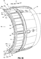
- FIG. 3A is an illustration of a perspective view of an exemplary embodiment of the load distribution panel assembly 60 of the load distribution panel system 10 (see FIGS. 2A , 7 ) of the disclosure.
- the load distribution panel assembly 60 comprises a panel structure 61.
- the panel structure 61 preferably comprises at least one panel portion 62a (see FIGS. 3A , 5A ) comprising at least one circumferential structural panel 70 (see FIG. 3A ) or at least one circumferential structural panel 70a (see FIG. 5A ).
- the panel structure 61 may comprise two panel portions 62a, 62b (see FIG. 3A ), such as two circumferential structural panels 70 (see FIG.
- each of the panel portions 62a, 62b have the upper end 64a and the lower end 64b, respectively.
- Each panel portion 62a, 62b may be in the form of a circumferential or curved bracket structure or another suitably shaped structure.
- the panel structure 61 (see FIGS. 3A , 7 ) may comprise a single unitary or monolithic structure comprising a single panel portion 62a, or may comprise two or more separate panel portions 62a, 62b that may be coupled or joined together.
- the two panel portions 62a, 62b preferably form a hoop configuration 94 when coupled together as the panel structure 61.
- the two panel portions 62a, 62b are preferably coupled together at respective upper ends 64a (see FIG. 3A ) via an upper beam assembly 96 (see FIG. 3A ), such as in the form of a hinge beam assembly 96a (see FIG. 3A ), and are preferably coupled together at respective lower ends 64b via a lower beam assembly 100 (see FIG. 3A ), such as in the form of a latch beam assembly 100a (see FIG. 3A ).
- the load distribution panel assembly 60 provides a uniform load distribution 156 (see FIG. 7 ) in the vehicle 12 (see FIGS. 1 , 7 ), such as in a gas turbine engine 16a (see FIGS. 2A , 7 ) in the vehicle 12.
- each panel portion 62a, 62b comprises the circumferential structural panel 70, preferably having a conical shape 72.
- each circumferential structural panel 70 of the load distribution panel assembly 60 comprises a first end 74a and a second end 74b, where the first end 74a is coupled to a fixed structure 76, such as a translating sleeve bulkhead 78, or such as the outer blade fitting 52 (see FIG. 2A ) or another suitable fixed structure 76.
- each circumferential structural panel 70 of the load distribution panel assembly 60 further comprises a first compliant portion 80, comprising a compliant barrel portion 80a, that extends away from the first end 74a.
- the first compliant portion 80 (see FIGS. 3A , 5A , 7 )_may extend axially (parallel to the axis of a load applying apparatus 50 (see FIGS. 3A )) away from the first end 74a, may extend radially away from the first end 74a, or may extend both axially and radially away from the first end 74a.
- the first compliant portion 80 has a first inner surface 84a (see FIG. 3A ) and a first outer surface 84b (see FIG. 3A ).
- each circumferential structural panel 70 of the load distribution panel assembly 60 further comprises a second stiffened portion 82 comprising a stiffened bulb portion 82a, angled with respect to the first compliant portion 80 and extending radially away from the first compliant portion 80, and terminating at the second end 74b.
- the second stiffened portion 82 (see FIG. 3A ), comprising a stiffened bulb portion 82a (see FIG. 3A ), has a second inner surface 86a (see FIG. 3A ) and a second outer surface 86b (see FIG. 3A ), and has a closed stiffened cavity portion 87a (see FIG. 3A ) integral with a perimeter lip portion 87b (see FIG. 3A ).
- the first compliant portion 80, comprising the compliant barrel portion 80a, and the second stiffened portion 82, comprising the stiffened bulb portion 82a, of the circumferential structural panel 70 may comprise a single monolithic or unitary structure, or alternatively, may comprise separate portions that may be joined or coupled together with attachment elements such as bolts, pins, or other suitable attachment elements.
- the load distribution panel system 10 may further comprise one or more clevis members 88 coupled to the second inner surface 86a of the second stiffened portion 82 of each circumferential structural panel 70, to facilitate attachment of the one or more load applying apparatuses 50, such as in the form of one or more thrust reverser actuation system (TRAS) actuators 50a.
- the clevis member 88 comprises one or more attachment holes 90 engageable to a tie rod (not shown) or another suitable attachment means.
- each load applying apparatus 50 such as in the form of TRAS actuator 50a, has a first end 108a attached to a translating sleeve 34 of a thrust reverser assembly 26, has a second end 108b attached to the closed stiffened cavity portion 87a of the second stiffened portion 82, and has a rod body 110 between the first end 108a and the second end 108b.
- the forward-aft direction arrow 39 indicates that the second end 108b (see FIG. 3A ) of each TRAS actuator 50a (see FIG. 3A ) is forward of the first end 108a (see FIG. 3A ), and that the first end 108a (see FIG. 3A ) is aft of the second end 108b (see FIG. 3A ).
- each load applying apparatus 50 such as in the form of TRAS actuator 50a, may be inserted through an attachment opening 106 and attached via one or more thrust reverser actuation system (TRAS) attach fittings 112 at locations 114 on the second inner surface 86a of the second stiffened portion 82.
- the load distribution panel system 10 may further comprise one or more support elements 92 and one or more power connectors 93, such as hydraulic power connectors, electrical power connectors, pneumatic power connectors, or another suitable power connector, to facilitate attachment and/or support of and power to the one or more load applying apparatuses 50, such as in the form of one or more thrust reverser actuation system (TRAS) actuators 50a.
- TRAS thrust reverser actuation system
- the load distribution panel system 10 may further comprise an upper beam assembly 96 coupled to an upper end 64a of each panel portion 62a, 62b.
- the upper beam assembly 96 such as in the form of hinge beam assembly 96a, may comprise one or more upper elements 68a, one or more upper beams 98, such as in the form of hinge beams 98a, and the first sliding track 44a (see FIG. 2B ).
- the load distribution panel system 10 may further comprise a lower beam assembly 100, such as in the form of latch beam assembly 100a, coupled to a lower end 64b of each panel portion 62a, 62b.
- the lower beam assembly 100 may comprise one or more lower elements 102, such as in the form of one or more latch elements 102a, and the second sliding track 44b (see FIG. 2B ).
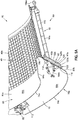
- FIG. 3B is an illustration of a perspective view of the panel portion 62a of the load distribution panel system 10 and the load distribution panel assembly 60 of FIG. 3A , with the plurality of cascade members 40, such as in the form of translating cascade baskets 40a, and the translating sleeve 34.
- the translating sleeve 34 is in the deployed position 58 to expose the plurality of cascade members 40.
- a forward-aft direction arrow 39 indicates that the circumferential structural panel 70 (see FIG. 3B ) and the plurality of cascade members 40 (see FIG. 3B ) are forward of the translating sleeve 34 (see FIG. 3B ), and that the translating sleeve (see FIG. 3B ) is aft of the circumferential structural panel 70 (see FIG. 3B ) and the plurality of cascade members 40 (see FIG. 3B ).
- FIG. 3B further shows the second stiffened portion 82, comprising the stiffened bulb portion 82a, the load applying apparatuses 50, such as in the form of TRAS actuators 50a, the clevis member 88 with attachment opening 90, the support element 92, the power connector, the TRAS attach fitting 112, the upper beam 98, and the lower beam 104.
- the load applying apparatuses 50 such as in the form of TRAS actuators 50a
- the clevis member 88 with attachment opening 90 the support element 92
- the power connector the TRAS attach fitting 112
- the upper beam 98 and the lower beam 104.
- FIG. 3C is an illustration of a perspective cutaway view of a partial portion of the panel portion 62a of the load distribution panel system 10 and the load distribution panel assembly 60 of FIG. 3A , with the plurality of cascade members 40, such as in the form of translating cascade baskets 40a, and the translating sleeve 34.
- the translating sleeve 34 is in the stowed position 58, and the load distribution panel assembly 60 has the first end 74a coupled to the fixed structure 76, such as the outer blade fitting 52, and has the second end 74b.
- the circumferential structural panel 70 includes the first compliant portion 80 (see FIG. 3C ), comprising the compliant barrel portion 80a (see FIG. 3C ), having the first inner surface 84a (see FIG. 3C ) and the first outer surface 84b (see FIG. 3C ).
- the circumferential structural panel 70 further includes the second stiffened portion 82 (see FIG. 3C ), comprising the stiffened bulb portion 82a (see FIG. 3C ), having the second inner surface 86a (see FIG. 3C ) and the second outer surface 86b (see FIG. 3C ).
- FIG. 3C further shows the load applying apparatus 50, such as in the form of TRAS actuator 50a, the clevis member 88 with attachment opening 90, the support elements 92, the power connectors 93, the TRAS attach fitting 112, and the latch beam 104.
- the load applying apparatus 50 such as in the form of TRAS actuator 50a
- the clevis member 88 with attachment opening 90 the support elements 92
- the power connectors 93 the TRAS attach fitting 112
- latch beam 104 latch beam 104
- FIG. 3D is an illustration of a perspective view of the panel portion 62a, with the conical shape 72, of load distribution panel assembly 60 of FIG. 3A , showing the circumferential structural panel 70 with a plurality of load applying apparatuses 50, such as in the form of TRAS actuators 50a.
- each load applying apparatus 50 such as in the form of TRAS actuator 50a, has a first end 108a, a second end 108b, and a rod body 110, and is attached through attachment opening 106 and is attached to the panel portion 62b via the TRAS attach fitting 112.
- the circumferential structural panel 70 includes the first compliant portion 80 (see FIG. 3D ), comprising compliant barrel portion 80a (see FIG. 3D ), having the first inner surface 84a (see FIG. 3D ) and the first outer surface 84b (see FIG. 3D ).
- the circumferential structural panel 70 further includes the second stiffened portion 82 (see FIG. 3D ), comprising the stiffened bulb portion 82a (see FIG. 3D ), having the second inner surface 86a (see FIG. 3D ) and the second outer surface 86b (see FIG. 3D).
- FIG. 3D further shows the first end 74a, the second end 74b, the clevis member 88 with attachment opening 90, and the support elements 92 and the power connector 93.
- FIG. 4A is an illustration of a cross-sectional side view of an exemplary embodiment of a circumferential structural panel 70 used in the load distribution panel system 10 (see FIGS. 3A , 7 ) of the disclosure.
- the circumferential structural panel 70 has the first end 74a and the second end 74b, and comprises the first compliant portion 80, comprising the compliant barrel portion 80a, having the first inner surface 84a and the first outer surface 84b.
- the circumferential structural panel 70 has the first end 74a and the second end 74b, and comprises the first compliant portion 80, comprising the compliant barrel portion 80a, having the first inner surface 84a and the first outer surface 84b.
- the circumferential structural panel 70 further comprises the second stiffened portion 82, comprising the stiffened bulb portion 82a, having the second inner surface 86a and the second outer surface 86b, and having the closed stiffened cavity portion 87a and the perimeter lip portion 87b.
- the closed stiffened cavity portion 87a has a sandwich structure 116 with a core interior 118 filled with a stiffened material 120 comprising a honeycomb core 120a.
- the core interior 118 may be filled with a stiffened material 120 in the form of a foam core 120b (see FIG. 5B ) or another suitable stiffened material, or, in examples helpful for understanding the claimed invention, the core interior may be a hollow core interior 118b (see FIG. 7 ).
- the closed stiffened cavity portion 87a (see FIG. 4A ) has a geometric configuration 122 comprising a parallelogram 122a.
- the closed stiffened cavity portion 87a may have another suitable geometric configuration 122, such as a trapezoid 122b (see FIG. 5B ), a rectangle 122c (see FIG. 7 ), an ellipse 122d (see FIG. 7 ), or another suitable geometric configuration 122.
- a trapezoid 122b see FIG. 5B
- a rectangle 122c see FIG. 7
- an ellipse 122d see FIG. 7
- another suitable geometric configuration 122 such as a trapezoid 122b (see FIG. 5B ), a rectangle 122c (see FIG. 7 ), an ellipse 122d (see FIG. 7 ), or another suitable geometric configuration 122.
- the second stiffened portion 82 comprising the stiffened bulb portion 82a
- the second stiffened portion 82 comprising the stiffened bulb portion 82a, is angled with respect to the first compliant portion 80 at the angle 126, preferably, in a range between 25° (twenty-five degrees) and 80° (eighty degrees); and more preferably angled at an angle 126 in a range between 45° (forty-five degrees) and 60° (sixty degrees).
- the most optimal angle (theta ⁇ ) will be a function of the stiffness of the materials that make up the constituent components, such as the first compliant portion 80 (see FIG. 7 ) and second stiffened portion 82 (see FIG. 7 ).
- the second stiffened portion 82 comprising the stiffened bulb portion 82a, creates a reinforced torque capable section 128 that allows the compliant barrel section 80a to function as a spring.
- FIG. 4B is an illustration of an enlarged perspective side view of an exemplary embodiment of the load distribution panel system 10 of the disclosure that incorporates the load distribution panel assembly 60 comprising the circumferential structural panel 70 of FIG. 4A .
- the panel portion 62a, with the conical shape 72, of load distribution panel assembly 60 shows the circumferential structural panel 70 with the load applying apparatus 50, such as in the form of TRAS actuator 50a.
- the load applying apparatus 50 such as in the form of TRAS actuator 50a, has the first end 108a, the second end 108b, and the rod body 110, and is attached to the panel portion 62a via the TRAS attach fitting 112.
- the circumferential structural panel 70 includes the first compliant portion 80 (see FIG. 4B ), comprising the compliant barrel portion 80a (see FIG. 4B ), having the first inner surface 84a (see FIG. 4B ) and the first outer surface 84b (see FIG. 4B ).
- the circumferential structural panel 70 further includes the second stiffened portion 82 (see FIG. 4B ), comprising the stiffened bulb portion 82a (see FIG. 4B ), having the second inner surface 86a (see FIG. 4B ) and the second outer surface 86b (see FIG. 4B ). As shown in FIG.
- the second stiffened portion 82 comprising the stiffened bulb portion 82a, has a core interior 118 filled with a stiffened material 120, such as in the form of a honeycomb core 120a, and has a geometric configuration 122, such as in the form of a parallelogram 122a.
- FIG. 4B further shows the first end 74a, the second end 74b, the clevis member 88 with attachment opening 90, and the support element 92 and power connector 93.
- the first end 74a (see FIG. 4B ) is attached to the fixed structure 76 (see FIG. 4B ), such as in the form of outer blade fitting 52, and the translating sleeve bulkhead 78.
- FIG. 4B further shows the plurality of cascade members 40, such as in the form of translating cascade baskets 40a.
- FIG. 5A is an illustration of an enlarged perspective partial side view of an embodiment of a load distribution panel system 10 of the disclosure that incorporates another embodiment of a circumferential structural panel 70a having a conical shape 72, of the disclosure.
- the first end 74a and the second end 74b both curve forward and project outwardly on the same side, as opposed to opposite sides, and the circumferential panel 70a has a curve 130 that causes the first compliant portion 80, comprising the compliant barrel portion 80a, to be curved forward in the same general direction as the second stiffened portion 82, comprising the stiffened bulb portion 82a.
- the circumferential structural panel 70a includes the first compliant portion 80 (see FIG. 5A ), comprising the compliant barrel portion 80a (see FIG. 5A ), having the first inner surface 84a (see FIG. 5A ) and the first outer surface 84b (see FIG. 5A ).
- the circumferential structural panel 70a further includes the second stiffened portion 82 (see FIG. 5A ), comprising the stiffened bulb portion 82a (see FIG. 5A ), having the second inner surface 86a (see FIG. 5A ) and the second outer surface 86b (see FIG. 5A ). As shown in FIG.
- the second stiffened portion 82 comprising the stiffened bulb portion 82a, has a closed stiffened cavity portion 87a, a perimeter lip portion 87b, a core interior 118 filled with a stiffened material 120, such as in the form of a foam core 120b, and has a geometric configuration 122, such as in the form of a trapezoid 122b.
- the core interior 118 may be filled with a stiffened material 120 in the form of a honeycomb core 120a (see FIG. 7 ) or another suitable stiffened material, or, in examples useful for understanding the claimed invention, the core interior may be a hollow core interior 118b (see FIG. 7 ).
- FIG. 5A further shows the load applying apparatus 50, such as in the form of TRAS actuator 50a, having the first end 108a, the second end 108b, and the rod body 110, and is attached to the load distribution panel assembly 60 via the TRAS attach fitting 112.
- FIG. 5A further shows the plurality of cascade members 40, such as in the form of fixed cascade baskets 40b.
- FIG. 5B is an illustration of a perspective partial side view of the load distribution panel system 10 with the load distribution panel assembly 60 comprising the circumferential structural panel 70a with the conical shape 72 of FIG. 5A , that also shows a translating sleeve 34 in a stowed position 56.
- the circumferential structural panel 70a includes the first end 74a and the second end 74b both curved forward and projecting outwardly on the same side and in the same direction, and the circumferential panel 70a has the curve 130 that causes the first compliant portion 80, comprising the compliant barrel portion 80a, to be curved forward in the same general direction as the second stiffened portion 82, comprising the stiffened bulb portion 82a.
- the circumferential structural panel 70a includes the first compliant portion 80 (see FIG. 5B ), comprising the compliant barrel portion 80a (see FIG. 5B ), having the first inner surface 84a (see FIG. 5B ) and the first outer surface 84b (see FIG. 5B ).
- the first end 74a is coupled or attached to a fixed structure 76, such as in the form of a load transfer fitting 132, at location 138.
- the circumferential structural panel 70a further includes the second stiffened portion 82 (see FIG. 5B ), comprising the stiffened bulb portion 82a (see FIG. 5B ), having the second inner surface 86a (see FIG. 5B ) and the second outer surface 86b (see FIG. 5B ).
- the second stiffened portion 82 comprising the stiffened bulb portion 82a, has a closed stiffened cavity portion 87a, a perimeter lip portion 87b, a core interior 118 filled with a stiffened material 120, such as in the form of a foam core 120b, and has a geometric configuration 122, such as in the form of a trapezoid 122b.
- FIG. 5B further shows the load applying apparatus 50, such as in the form of TRAS actuator 50a, having the first end 108a, the second end 108b, and the rod body 110, and is attached to the load distribution panel assembly 60 via the TRAS attach fitting 112.
- FIG. 5B further shows the plurality of cascade members 40, such as in the form of fixed cascade baskets 40b, and shows blocker door attachment devices 134.
- FIG. 5B further shows the clevis member 88 with attachment opening 90.
- FIG. 5C is an illustration of a perspective partial side view of the load distribution panel system 10 with the load distribution panel assembly 60 comprising the circumferential structural panel 70a with the conical shape 72 of FIG. 5B , that also shows a translating sleeve 34 in a deployed position 58.
- the circumferential structural panel 70a includes the curve 130 that causes the first compliant portion 80, comprising the compliant barrel portion 80a, to be curved forward in the same general direction as the second stiffened portion 82, comprising the stiffened bulb portion 82a.
- the circumferential structural panel 70a includes the first compliant portion 80 (see FIG. 5C ), comprising the compliant barrel portion 80a (see FIG. 5C ), having the first inner surface 84a (see FIG. 5C ) and the first outer surface 84b (see FIG. 5C ).
- the first compliant portion 80 comprising the compliant barrel portion 80a, is coupled or attached to the fixed structure 76, such as in the form of the load transfer fitting 132.
- the circumferential structural panel 70a further includes the second stiffened portion 82 (see FIG. 5C ), comprising the stiffened bulb portion 82a (see FIG. 5C ), having the second inner surface 86a (see FIG. C) and the second outer surface 86b (see FIG. 5C ).
- the second stiffened portion 82 comprising the stiffened bulb portion 82a, has the core interior 118 with the stiffened material 120, such as in the form of the foam core 120b, and has the geometric configuration 122, such as in the form of the trapezoid 122b.
- FIG. 5C further shows the load applying apparatus 50, such as in the form of TRAS actuator 50a, having the first end 108a, the second end 108b, and the rod body 110, and is attached to the load distribution panel assembly 60 through the attachment opening 106 and via the TRAS attach fitting 112.
- FIG. 5C further shows the clevis member 88, the plurality of cascade members 40, such as in the form of fixed cascade baskets 40b, and shows attachment devices 134 and the bolted panel 136 abutting the circumferential structural panel 70a.
- FIG. 5B further shows the clevis member 88 with attachment opening 90.
- FIG. 6A is a schematic illustration of a load path configuration 140 of an embodiment of a load distribution panel assembly 60 comprising the circumferential structural panel 70 of the load distribution panel system 10 (see FIGS. 3A , 7 ) of the disclosure.
- FIG. 6A shows the load applying apparatus 50, such as in the form of TRAS actuator 50a, applying a fore/aft point load 142 to the load distribution panel assembly 60 comprising the circumferential structural panel 70, at point load interface 143 at the second stiffened portion 82.
- FIG. 6A further shows the clevis 88 with the attachment opening 90, and the angle 126 formed by the second stiffened portion 82 bending upwardly from the x-axis 127 in line with the plane of the first compliant portion 80.
- FIG. 6A further shows the first compliant portion 80 coupled to the fixed structure 76, such as in the form of outer blade fitting 52.
- the outer blade fitting 52 (see FIG. 6A ) is inserted in or coupled to the outer groove fitting 54 (see FIG. 6A ), which is coupled or attached to the engine fan case 48 (see FIG. 6A ) surrounding or shrouding the fan 46 (see FIG. 6A ).
- an outer blade fitting reaction force reacts to the fore/aft point load 142.
- FIG. 6A further shows a load offset 146 between the load applying apparatus 50 and the load distribution panel assembly 60.
- the load distribution panel assembly 60 takes the load 142 with offset 146 (see FIG. 6A ) and reacts it in in-plane loads 147 (see FIG. 6B ) creating minimal bending in the load distribution panel assembly 60.
- FIG. 6A further shows a load path 148 of the fore/aft point load 142 to the fixed structure 76, such as in the form of the outer blade fitting 52, that is more efficient than known assemblies, systems, and methods.
- the primary feature that drives a more efficient load path 148 is the use of the second stiffened portion 82 (see FIG.
- a forward-aft direction arrow 39 indicates that the load path 148 (see FIG. 6A ) transmitting from forward to aft.
- FIG. 6B is a schematic illustration of a loading diagram 150 of an embodiment of a load distribution panel assembly 60 comprising the circumferential structural panel 70 of FIG. 6A .
- FIG. 6B shows the first end 74a and the second end 74b of the load distribution panel assembly 60, and shows the first compliant portion 80 and the second stiffened portion 82 of the load distribution panel assembly 60.
- FIG. 6B further shows the fore/aft point load 142 to the load distribution panel assembly 60 comprising the circumferential structural panel 70, at the second stiffened portion 82.
- FIG. 6B shows the outer blade fitting reaction force 144 reacting to the fore/aft point load 142.
- the load distribution panel assembly 60 (see FIG. 6B ) effectively converts the fore/aft point load 142 (see FIG. 6B ) applied to the load distribution panel assembly 60 (see FIG. 6B ) by the load applying apparatus 50 (see FIG. 6A ), such as the TRAS actuator 50a (see FIG. 6A ), to a hoop tension load 152 (see FIG. 6B ) and a hoop compression load 154 (see FIG. 6B ), and reacts the load offset 146 (see FIG. 6A ) between the load applying apparatus 50 (see FIG. 6A ) and the load distribution panel assembly 60 (see FIG. 6B ), in one or more in-plane loads 147 (see FIG. 6B ).
- This provides a uniform load distribution 156 (see FIG. 6B ) of the fore/aft point load 142 (see FIG. 6B ), through the load distribution panel assembly 60 (see FIG. 6B ), and to the fixed structure 76 (see FIG. 6A ).
- the load distribution panel assembly 60 (see FIG. 6B ) is more efficient in the continuous and uniform distribution of the fore/aft point load 142 (see FIG. 6B ) onto the fixed structure 76 (see FIG. 6A ) of the gas turbine engine 16a (see FIGS. 2A , 7 ), as compared to known systems, assemblies, and methods for a gas turbine engine.
- the fore/aft point load 142 (see FIG. 6B ) and the outer blade fitting reaction force 144 (see FIG. 6B ) generate a moment couple 158 (see FIG. 6B ), which is reacted as the hoop tension load 152 (see FIG. 6B ) and the hoop compression load 154 (see FIG. 6B ) in the hoop direction of the second stiffened portion 82 (see FIG. 6B ), through allowing the second stiffened portion 82 to rotate in the direction of the moment couple 158 (see FIG. 6B ) into the first compliant portion 80 (see FIG. 6B ). As shown in FIG.
- the load path 148 transmits the fore/aft point load 142 which transfer or jump over the load offset 146 (see FIG. 6A ) and into the in-plane loads 147, instead of out-of-plane loads, in the load distribution panel assembly 60, and transfer to the fixed structure 76 (see FIG. 6A ), such as the outer blade fitting 52 (see FIG. 6A ), all with minimal supporting structure or reinforcement.
- FIG. 7 is an illustration of a functional block diagram showing an exemplary embodiment of a load distribution panel system 10 the disclosure.
- a load distribution panel system 10 for providing a uniform load distribution 156 in an engine 16, such as a gas turbine engine 16a of a vehicle 12.
- the vehicle 12 comprises an aircraft 12a, or, in examples useful for understanding the claimed invention, an automobile 12b, a watercraft such as a submarine 12d, or another suitable vehicle 12.
- the engine 16 such as the gas turbine engine 16a, may comprise a thrust reverser assembly 26, a thrust reverser cowl 24 with an inlet cowl 30, a fixed member 32, and a translating member 34, a plurality of cascade members 40, and one or more fixed structures 76.
- the plurality of cascade members 40 may comprise translating cascade baskets 40a (see FIGS. 2A , 3B ) or fixed cascade baskets 40b (see FIG. 5A ). As shown in FIG.
- the one or more fixed structures 76 may comprise a gas turbine engine fixed structure 76a comprising one of, an engine fan case 48, an outer blade fitting 52, an outer groove fitting 54, a translating sleeve bulkhead 78, a load transfer fitting 132, or another suitable fixed structure.
- the load distribution panel system 10 comprises a load distribution panel assembly 60 having a panel structure 61 with at least one panel portion 62a, and in an embodiment, for example, two panel portions 62a, 62b, or more than two panel portions.
- Each panel portion 62a, 62b comprises a circumferential structural panel 70 (see FIG. 3A ) or circumferential structural panel 70a (see FIG. 5B ).
- Each circumferential structural panel 70, 70a has a conical shape 72, a cylindrical shape, a circular shape, an axisymmetric shape, or another suitable shape.
- each circumferential structural panel 70, 70a comprises a first end 74a and a second end 74b, a first compliant portion 80, and a second stiffened portion 82.
- the first end 74a (see FIG. 7 ) is coupled to the fixed structure 76 (see FIG. 7 ) of the gas turbine engine 16a (see FIG. 7 ) of the vehicle 12 (see FIG. 7 ).
- the first compliant portion 80 comprises a compliant barrel portion 80a.
- the first compliant portion 80 comprising the compliant barrel portion 80a, extends radially away from the first end 74a.
- the first compliant portion 80 (see FIG. 7 ), comprising the compliant barrel portion 80a (see FIG. 7 ) has a first inner surface 84a (see FIGS. 3A , 5B ) and a first outer surface 84b (see FIGS. 3A , 5B ).
- the second stiffened portion 82 comprises a stiffened bulb portion 82a having a closed stiffened cavity portion 87a integral with a perimeter lip portion 87b.
- the second stiffened portion 82 comprising the stiffened bulb portion 82a, is angled with respect to the first compliant portion 80, comprising the compliant barrel portion 80a, and extends radially away from the first compliant portion 80, comprising the compliant barrel portion 80a, and terminates at the second end 74b.
- the second stiffened portion 82 (see FIG. 7 ), comprising the stiffened bulb portion 82a (see FIG. 7 ), is preferably angled with respect to the first compliant portion 80 (see FIG.
- the second stiffened portion 82 (see FIGS. 3A , 5B , 7 ), comprising the stiffened bulb portion 82a (see FIGS. 3A , 5B , 7 ), has a second inner surface 86a (see FIGS. 3A , 5B ) and a second outer surface 86b (see FIGS. 3A , 5B ).
- the second stiffened portion 82 comprising the stiffened bulb portion 82a, comprises a sandwich structure 116 and a non-quasi isotropic laminate 117 may be used to form the second stiffened portion 82.
- FIG. 7 the second stiffened portion 82, comprising the stiffened bulb portion 82a, comprises a sandwich structure 116 and a non-quasi isotropic laminate 117 may be used to form the second stiffened portion 82.
- the closed stiffened cavity portion 87a of the second stiffened portion 82 comprising the stiffened bulb portion 82a
- the core interior 118 (see FIG. 7 ) of the closed stiffened cavity portion 87a (see FIG. 7 ) has a hollow core interior 118b (see FIG. 7 ).
- the closed stiffened cavity portion 87a of the second stiffened portion 82 comprising the stiffened bulb portion 82a, has a geometric configuration 122 comprising one of, a parallelogram 122a, a trapezoid 122b, a rectangle 122c, an ellipse 122d, or another suitable geometric configuration.
- the second stiffened portion 82 (see FIG. 7 ), comprising the stiffened bulb portion 82a (see FIG. 7 ), is a reinforced torque capable section 128 (see FIG. 7 ).
- FIG. 7 is a reinforced torque capable section 128 (see FIG. 7 ).
- first compliant portion 80 and the second stiffened portion 82 have a stiffness 124, where the second stiffened portion 82, comprising the stiffened bulb portion 82a, has a stiffness 124, such as a second stiffened portion bending and torsion stiffness 124b, that is much greater, for example, 100 (one hundred) times to 1000 (one thousand) times greater, than a stiffness 124, such as a first compliant portion bending and torsion stiffness 124a, of the first compliant portion 80, such as in the form of compliant barrel portion 80a.
- a stiffness 124 such as a second stiffened portion bending and torsion stiffness 124b
- the load distribution panel system 10 further comprises one or more load applying apparatuses 50, such as in the form of thrust reverser actuation system (TRAS) actuators 50a, which is/are coupled to the load distribution panel assembly 60.
- the TRAS actuators 50a may be coupled or attached to the load distribution panel assembly 60 (see FIG. 7 ) with one or more TRAS attach fittings 112 (see FIGS. 3A , 5B , 7 ).
- FIG. 7 the load distribution panel system 10
- the TRAS actuators 50a may be coupled or attached to the load distribution panel assembly 60 (see FIG. 7 ) with one or more TRAS attach fittings 112 (see FIGS. 3A , 5B , 7 ).
- the load distribution panel system 10 may further comprise one or more clevis members 88 coupled to the second inner surface 86a of the second stiffened portion 82, comprising the stiffened bulb portion 82a, of each circumferential structural panel 70, 70a, to facilitate attachment of the one or more load applying apparatuses 50, such as in the form of TRAS actuators 50a, to the load distribution panel assembly 60.
- the load distribution panel system 10 may further comprise an upper beam assembly 96 coupled to an upper end 64a (see FIG. 3A ) of each panel portion 62a, 62b.
- the upper beam assembly 96 may comprise one or more upper elements 68, such as in the form of hinge elements 68a (see FIG. 2B ).
- the load distribution panel system 10 may further comprise a lower beam assembly 100 coupled to a lower end 64b (see FIG. 3A ) of each panel portion 62a, 62b.
- the lower beam assembly 100 such as in the form of latch beam assembly 100a, may comprise one or more lower elements 102, such as in the form of latch elements 102a.
- the load distribution panel assembly 60 converts one or more structural loads 145 (see FIG. 7 ), such as fore/aft point loads 142 (see FIG. 7 ), applied to the load distribution panel assembly 60 (see FIG. 7 ) by the one or more load applying apparatuses 50 (see FIG. 7 ), such as the TRAS actuators 50a (see FIG. 7 ), to a hoop tension load 152 (see FIG. 7 ) and a hoop compression load 154 (see FIG. 7 ).
- the load distribution panel assembly 60 reacts a load offset 146 between the one or more load applying apparatuses 50 (see FIG. 7 ), such as the TRAS actuators 50a (see FIG.
- the fore/aft point loads 142 (see FIG. 7 ) and the outer blade fitting reaction force 144 (see FIGS. 6B , 7 ) generate a force couple 158 (see FIG. 7 ), which is reacted as hoop tension load 152 (see FIGS. 6B , 7 ) and hoop compression load 154 (see FIGS. 6B , 7 ) in the hoop direction of the second stiffened portion 82 (see FIGS. 4A , 6A , 7 ), comprising the stiffened bulb portion 82a (see FIGS. 4A , 7 ), through allowing the second stiffened portion 82, comprising the stiffened bulb portion 82a, to rotate in the direction of the force couple 158 (see FIG.
- the force couple 158 includes two equal and opposite forces whose line of action do not coincide.
- a moment 159 (see FIG. 7 ) generated by force couple 158 (see FIG. 7 ) is the product of the magnitude of one of the forces and the perpendicular distance between their lines of action.
- the fore/aft point loads 142 arrive at the outer blade fitting 52 (see FIG. 7 ) as a uniform load distribution 156 (see FIG. 7 ), instead of as discrete point loads.
- the first compliant portion 80 (see FIGS.
- FIGS. 4A , 6A , 7 comprising the compliant barrel portion 80a (see FIGS. 4A , 7 ), has a compliant composition which allows a hinging effect 157 (see FIG. 7 ) which converts the fore/aft point loads 142 (see FIG. 7 ) to the hoop tension load 152 (see FIGS. 6B , 7 ) and the hoop compression load 154 (see FIGS. 6B , 7 ).
- the load distribution panel assembly 60 (see FIG. 7 ) and the load distribution panel system 10 (see FIG. 7 ) provide a load path 148 (see FIG. 7 ) for the fore/aft point loads 142 (see FIG. 7 ) to the fixed structure 76 (see FIG. 7 ), such as the outer blade fitting 52 (see FIG. 7 ).
- the load distribution panel assembly 60 (see FIG. 7 ) and the load distribution panel system 10 (see FIG. 7 ) provide for a reduced structural reinforcement 162 (see FIG. 7 ) or support, a reduced complexity 164 (see FIG. 7 ), and a reduced part count 166 (see FIG. 7 ), as compared to known assemblies, systems, and methods for a gas turbine engine.
- FIG. 8 is an illustration of a flow diagram showing an exemplary embodiment of a method 200 of the disclosure.
- the method 200 comprises step 202 of installing in the gas turbine engine 16a (see FIGS. 1 , 2A , 7 ), a load distribution panel system 10 (see FIGS. 1 , 3A , 5B , 7 ) comprising a load distribution panel assembly 60 (see FIGS. 3A , 5B , 7 ), and one or more load applying apparatuses 50 (see FIGS. 3A , 5B , 7 ) coupled to the load distribution panel assembly 60.
- the load distribution panel assembly 60 (see FIGS. 3A , 5A , 7 ) comprise a panel structure 61 (see FIG. 3A ) having at least two panel portions 62a, 62b (see FIG. 3A ).
- Each panel portion 62a, 62b (see FIG. 3A ) comprises a circumferential structural panel 70, 70a (see FIGS. 3A , 4A , 5B , 7 ).
- Each circumferential structural panel 70, 70a (see FIGS. 3A , 4A , 5B , 7 ) comprises a first end 74a (see FIGS. 3A , 4A , 5B , 7 ) and a second end 74b (see FIGS. 3A , 4A , 5B , 7 ) coupled to a fixed structure 76 (see FIGS. 3A , 5B , 7 ).
- Each circumferential structural panel 70, 70a further comprises a first compliant portion 80 (see FIGS. 3 , 4A , 5B , 7 ) extending radially away from the first end 74a (see FIGS. 3A , 4A , 5B , 7 ).
- the first compliant portion 80 (see FIGS. 3A , 4A , 5B ) has a first inner surface 84a (see FIGS. 3A , 4A , 5B ) and a first outer surface 84b (see FIGS. 3A , 4A , 5B ).
- Each circumferential structural panel 70, 70a further comprises a second stiffened portion 82 (see FIGS. 3A , 4A , 5B , 7 ) angled with respect to the first compliant portion 80 (see FIGS. 3A , 4A , 5B , 7 ) and extending radially away from the first compliant portion 80, and terminating at the second end 74b (see FIGS. 3A , 4A , 5B , 7 ).
- the step 202 (see FIG. 8 ) of installing the load distribution panel system 10 (see FIGS. 1 , 3A , 5B , 7 ) in the gas turbine engine 16a (see FIGS.
- 1 , 2A , 7 comprises angling the second stiffened portion 82 (see FIGS. 3A , 4A , 5B , 7 ) with respect to the first compliant portion 80 (see FIGS. 3 , 4A , 5B , 7 ), preferably, at an angle 126 (see FIGS. 4A , 6A ) between 25° (twenty-five degrees) and 80° (eighty degrees); and more preferably, at an angle 126 between 45° (forty-five degrees) and 60° (sixty degrees).
- the second stiffened portion 82 (see FIGS. 3A , 4A , 5B ) has a second inner surface 86a (see FIGS. 3A , 4A , 5B ) and a second outer surface 86b (see FIGS. 3A , 4A , 5B ), and has a closed stiffened cavity portion 87a (see FIGS. 3A , 4A , 5B ) integral with a perimeter lip portion 87b (see FIGS. 3A , 4A , 5B ).
- the step 202 (see FIG. 8 ) of installing the load distribution panel system 10 (see FIGS. 1 , 3A , 5B , 7 ) in the gas turbine engine 16a (see FIGS. 1 , 2A , 7 ) comprises installing the load distribution panel system 10 (see FIGS. 1 , 3A , 5B , 7 ) in the gas turbine engine 16a (see FIGS. 1 , 2A , 7 ) of the vehicle 12 (see FIGS. 1 , 7 ) comprising one of, an aircraft 12a (see FIGS. 1 , 7 ), an automobile 12b (see FIG. 7 ), a watercraft 12c (see FIG. 7 ), a submarine 12d (see FIG. 7 ), or another suitable vehicle 12 (see FIG. 7 ).
- the method 200 further comprises step 204 of coupling the first end 74a (see FIGS. 3A , 4A , 5B , 7 ) of the circumferential structural panel 70, 70a (see FIGS. 3A , 4A , 5B , 7 ) of the load distribution panel assembly 60 (see FIGS. 3A , 4A , 5B , 7 ) to the fixed structure 76 (see FIGS. 3A , 5B , 7 ) of the gas turbine engine 16a (see FIGS. 1 , 2A , 7 ).
- an engine fan case 48
- the method 200 further comprises step 206 of applying, with the one or more load applying apparatuses 50 (see FIGS. 3A , 5B , 6A-6B , 7 ), one or more fore/aft point loads 142 (see FIGS. 6A-6B , 7 ) to the load distribution panel assembly 60 (see FIGS. 3A , 4A , 5B , 7 ).
- the step 206 (see FIG. 8 ) of applying, with the one or more load applying apparatuses 50 (see FIGS. 3A , 5B , 6A-6B , 7 ), one or more fore/aft point loads 142 (see FIGS. 6A-6B ) to the load distribution panel assembly 60 (see FIGS.
- 3A , 5B , 6A-6B , 7 comprises applying, with the one or more load applying apparatuses 50 (see FIGS. 3A , 5B , 6A-6B , 7 ), comprising one or more thrust reverser actuation system (TRAS) actuators 50a (see FIGS. 2A , 3A , 5B , 6A , 7 ) having a first end 108a (see FIGS. 3A , 5B ) attached to a translating sleeve 34 (see FIG. 5B ) of a thrust reverser assembly 26 (see FIG. 2A ), and having a second end 108b (see FIGS. 3A , 5B ) attached to the closed stiffened cavity portion 87a (see FIGS. 3A , 5B ) of the second stiffened portion 82 (see FIGS. 3A , 5B ).
- TAS thrust reverser actuation system
- the method 200 further comprises step 208 of using the load distribution panel assembly 60 (see FIGS. 3A , 4A , 5B , 7 ) to convert the one or more fore/aft point loads 142 (see FIGS. 6A-6B , 7 ) applied to the load distribution panel assembly 60, to a hoop tension load 152 (see FIGS. 6A-6B , 7 ) and a hoop compression load 154 (see FIGS. 6A-6B , 7 ), and to react a load offset 146 (see FIG. 6A , 7 ) between the one or more load applying apparatuses 50 (see FIGS.
- the method 200 does not require additional structural support or reinforcement to react or overcome the load offset 146 (see FIG. 6A ), and thus results in reduced structural reinforcement 162 (see FIG. 7 ) required, reduced complexity 164 (see FIG. 7 ), and reduced part count 166 (see FIG. 7 ), as compared to known methods of load distribution in a gas turbine engine.
- FIG. 9 is an illustration of a flow diagram of an aircraft manufacturing and service method 300.
- FIG. 10 is an illustration of a functional block diagram of an aircraft 320. Referring to FIGS. 9-10 , embodiments of the disclosure may be described in the context of the aircraft manufacturing and service method 300 as shown in FIG. 9 , and the aircraft 320 as shown in FIG. 10 .
- exemplary aircraft manufacturing and service method 300 may include specification and design 302 of the aircraft 320 and material procurement 304. As further shown in FIG. 9 , during manufacturing, component and subassembly manufacturing 306 and system integration 308 of the aircraft 320 takes place. Thereafter, the aircraft 320 may go through certification and delivery 310 (see FIG. 9 ) in order to be placed in service 312 (see FIG. 9 ). While in service 312 by a customer, the aircraft 320 may be scheduled for routine maintenance and service 314 (see FIG. 9 ) (which may also include modification, reconfiguration, refurbishment, and other suitable services).
- Each of the processes of the aircraft manufacturing and service method 300 may be performed or carried out by a system integrator, a third party, and/or an operator (e.g., a customer).
- a system integrator may include, without limitation, any number of aircraft manufacturers and major-system subcontractors.
- a third party may include, without limitation, any number of vendors, subcontractors, and suppliers.
- An operator may include an airline, leasing company, military entity, service organization, and other suitable operators.
- the aircraft 320 produced by the exemplary aircraft manufacturing and service method 300 may include an airframe 322 with a plurality of systems 324 and an interior 326.
- the plurality of systems 324 may include one or more of a propulsion system 328 (see FIG. 10 ), an electrical system 330 (see FIG. 10 ), a hydraulic system 332 (see FIG. 10 ), and an environmental system 334 (see FIG. 10 ). Any number of other systems may be included.
- a propulsion system 328 see FIG. 10
- an electrical system 330 see FIG. 10
- a hydraulic system 332 see FIG. 10
- an environmental system 334 see FIG. 10
- Any number of other systems may be included.
- an aerospace example is shown, the principles of the disclosure may be applied to other industries, such as the automotive industry.
- Methods and systems embodied herein may be employed during any one or more of the stages of the aircraft manufacturing and service method 300 (see FIG. 9 ).
- components or subassemblies corresponding to component and subassembly manufacturing 306 may be fabricated or manufactured in a manner similar to components or subassemblies produced while the aircraft 320 (see FIG. 10 ) is in service 312 (see FIG. 9 ).
- one or more apparatus embodiments, method embodiments, or a combination thereof may be utilized during component and subassembly manufacturing 306 (see FIG. 9 ) and system integration 308 (see FIG. 9 ), for example, by substantially expediting assembly of or reducing the cost of the aircraft 320 (see FIG. 10 ).
- apparatus embodiments, method embodiments, or a combination thereof may be utilized while the aircraft 320 (see FIG. 10 ) is in service 312 (see FIG. 9 ), for example and without limitation, to maintenance and service 314 (see FIG. 9 ).
- Embodiments of the load distribution panel system 10 see FIGS. 3A , 5B , 7 ), the load distribution panel assembly 60 (see FIGS. 3A , 5B , 7 ), and the method 200 (see FIG. 8 ) for providing a uniform load distribution 156 (see FIGS. 6B , 7 ) in a gas turbine engine 16a (see FIGS. 1 , 2A , 7 ) effectively convert one or more fore/aft point loads 142 (see FIGS. 6A-6B , 7 ) applied to the load distribution panel assembly 60 (see FIGS. 3A , 5B , 7 ) by the one or more load applying apparatuses 50 (see FIGS.
- FIGS. 6A , 7 such as the one or more TRAS actuators 50a (see FIGS. 6A , 7 ), to a hoop tension load 152 (see FIGS. 6B , 7 ) and a hoop compression load 154 (see FIGS. 6B , 7 ), and react a load offset 146 (see FIGS. 6A , 7 ) between the one or more load applying apparatuses 50 (see FIGS. 6A , 7 ) and the load distribution panel assembly 60, in one or more in-plane loads 147 (see FIGS. 6B , 7 ).
- This provides a uniform load distribution 156 (see FIGS. 6B , 7 ) of the one or more fore/aft point loads 142 (see FIGS.
- Embodiments of the load distribution panel system 10 are more efficient in the continuous and uniform distribution of the fore/aft point loads 142 (see FIGS. 6A-6B , 7 ) onto the fixed structure 76 (see FIGS. 6A , 7 ) of the gas turbine engine 16a (see FIGS. 2A , 7 ), as compared to known systems, assemblies, and methods for a gas turbine engine.
- embodiments of the load distribution panel system 10 (see FIGS. 3A , 5B , 7 ), the load distribution panel assembly 60 (see FIGS. 3A , 5B , 7 ), and the method 200 (see FIG. 8 ) effectively distribute the hoop tension load 152 (see FIGS. 6B , 7 ) and the hoop compression load 154 (see FIGS. 6B , 7 ) in in-plane loads 147 (see FIG. 6B ) onto the circumferential structural panel 70 (see FIGS. 6B , 7 ) of the load distribution panel assembly 60 (see FIGS. 6B , 7 ).
- the primary feature that drives a more efficient load path 148 (see FIGS.
- the second stiffened portion 82 is the use of the second stiffened portion 82, comprising the stiffened bulb portion 82a (see FIGS. 4A , 7 ), which is angled, with respect to the first compliant portion 80 (see FIGS. 4A , 7 ), comprising the compliant barrel portion 80a (see FIGS. 4A , 7 ), preferably, at an angle 126 (see FIGS. 4A , 7 ) of between 25° (twenty-five degrees) and 80° (eighty degrees); and more preferably, at an angle 126 between 45° (forty-five degrees) and 60° (sixty degrees).
- the second stiffened portion 82 (see FIGS.
- FIGS. 4A , 7 is preferably in the form of a reinforced torque capable section 128 (see FIG. 7 ) and is coupled to the first compliant portion 80 (see FIGS. 4A , 7 ), which has a compliant composition that allows a hinging effect 157 (see FIG. 7 ) to convert the fore/aft point loads 142 (see FIGS. 6A-6B , 7 ) to the hoop tension load 152 (see FIGS. 6B , 7 ) and the hoop compression load 154 (see FIGS. 6B , 7 ).
- Important dimensions of the load distribution panel assembly 60 include the load offset 146 (see FIGS.
- FIGS. 6A , 7 the one or more load applying apparatuses 50 (see FIGS. 6A , 7 ), such as the one or more TRAS actuators 50a (see FIGS. 6A , 7 ), and the load distribution panel assembly 60 (see FIGS. 3A , 5B , 7 ), as well as the angle 126 (see FIGS. 4A , 7 ) formed between the second stiffened portion 82 and the first compliant portion 80.
- the load distribution panel assembly 60 takes the load offset 146 (see FIG. 6A ) and reacts it in in-plane loads 147 (see FIG. 6B ) without creating any bending in the load distribution panel assembly 60.
- the load distribution panel assembly 60 acts as an extension to the fixed structure 76 (see FIGS. 3A , 5B , 6A ), such as the outer blade fitting 52 (see FIGS. 2A , 6A ) (or other fixed structure), which is coupled to the outer groove fitting 54 (see FIGS. 2A , 6A ), which is attached to the engine fan case 48 (see FIGS. 2A , 6A ), of, for example, a thrust reverser assembly 26 (see FIG. 2A ), and thus provides a load path 148 (see FIGS. 6A-6B ) for the fore/aft point loads 142 (see FIGS.
- the fore/aft point loads 142 transfer or arrive at the fixed structure 76, such as the outer blade fitting 52 (see FIGS. 2A , 6A ) (or other fixed structure), as a uniform load distribution 156 (see FIGS. 6B , 7 ), instead of as discrete point loads.
- the load distribution panel assembly 60 see FIGS.
- the fore/aft point loads 142 (see FIGS. 6A-6B ) transfer or jump over the load offset 146 and into in-plane loads 147 (see FIG. 6B ) in the load distribution panel assembly 60 (see FIGS. 3A , 5B , 7 ), and transfer to the fixed structure 76 (see FIG. 6A ), such as the outer blade fitting 52 (see FIG. 6A ), all with minimal supporting structure or reinforcement.
- Embodiments of the load distribution panel system 10 greatly reduce the amount of required structural support or reinforcement for the load path 148 (see FIGS. 6A-6B ) and provide a reduced structural reinforcement 162 (see FIG. 7 ) for the load path 148 (see FIGS. 6A-6B ), as compared to known systems, assemblies, and methods for a gas turbine engine.
- embodiments of the load distribution panel system 10 see FIGS. 3A , 5B , 7 ), the load distribution panel assembly 60 (see FIGS.
- the load distribution panel assembly 60 may preferably be made with lightweight materials because of the efficiency of the load carrying capability, and thus may reduce weight of the vehicle 12 (see FIGS. 1 , 7 ), such as the aircraft 12a (see FIGS. 1 , 7 ).
- the uniform load distribution 156 may reduce the amount of material used in the engine assembly 28 (see FIG. 2A ), such as the engine fan case 48 (see FIGS. 2A , 6A ), thus further reducing weight of the vehicle 12 (see FIGS. 1 , 7 ), such as the aircraft 12a (see FIGS. 1 , 7 ), while still maintaining the same structural capability.
- the stiffened bulb portion 82a (see FIGS. 4A , 7 ) of the load distribution panel assembly 60 simplifies the design and reduces the overall weight by about fifty (50) pounds or by about 50%, as compared to known designs of assemblies and systems for a gas turbine engine.
- the simple design of the load distribution panel assembly 60 allows for a faster production and more efficient manufacturing, thus resulting in decreased manufacturing costs.
- the simple, open design of the load distribution panel assembly 60 allows for easy and quick inspection.
Landscapes
- Engineering & Computer Science (AREA)
- Chemical & Material Sciences (AREA)
- Combustion & Propulsion (AREA)
- Mechanical Engineering (AREA)
- General Engineering & Computer Science (AREA)
- Aviation & Aerospace Engineering (AREA)
- Structures Of Non-Positive Displacement Pumps (AREA)
- Filling Or Discharging Of Gas Storage Vessels (AREA)
Claims (13)
- Ensemble de panneaux de répartition de charge (60) pour fournir une répartition de charge uniforme (156) dans un inverseur de poussée d'un turbomoteur d'un avion, l'ensemble de panneaux de répartition de charge (60) comprenant :une structure de panneaux (61) comprenant au moins un panneau structurel circonférentiel (70), le panneau structurel circonférentiel (70) comprenant :une première extrémité (74a) et une seconde extrémité (74b), la première extrémité (74a) étant configurée pour être couplée à une structure fixe (76) du turbomoteur ;une première partie souple (80) s'étendant à distance de la première extrémité (74a), la première partie souple (80) comprenant une partie de barillet souple (80a) et ayant une première surface intérieure (84a) et une première surface extérieure (84b) ; etune seconde partie renforcée (82) formant un angle par rapport à la première partie souple (80) et s'étendant radialement à distance de la première partie souple (80), et se terminant au niveau de la seconde extrémité (74b), la seconde partie renforcée (82) comprenant une partie renforcée (82a) formant un bulbe et ayant une seconde surface intérieure (86a) et une seconde surface extérieure (86b), et ayant une partie renforcée fermée (87a) formant une cavité solidaire d'une partie périphérique (87b) formant une lèvre comprenant un intérieur (118a) à âme pleine, ledit intérieur étant rempli d'un matériau renforcé (120) comprenant l'une d'une âme en nid d'abeille (120a) et d'une âme en mousse (120b) ;ensemble dans lequel la seconde partie renforcée a une rigidité qui est plus forte qu'une rigidité de la première partie souple ;de sorte que l'ensemble de panneaux de répartition de charge (60) est conçu pour convertir une ou plusieurs charge(s) ponctuelle(s) avant/arrière (142) appliquée(s) à une interface de charges ponctuelles (143) sur la seconde partie renforcée de l'ensemble de panneaux de répartition de charge (60), par un ou plusieurs appareil(s) d'application de charge (50), en une charge de tension circonférentielle (152) et en une charge de compression circonférentielle (154), et conçu pour réagir à un décalage de charge (146) se produisant entre l'un ou plusieurs des appareils d'application de charge (50) et l'ensemble de panneaux de répartition de charge (60), dans une ou plusieurs charges dans le plan, afin de fournir à la structure fixe (76), par l'ensemble de panneaux de répartition de charge (60), la répartition de charge uniforme (156) de l'une ou de plusieurs des charges ponctuelles avant/arrière (142).
- Ensemble de panneaux de répartition de charge (60) selon la revendication 1, comprenant en outre un ou plusieurs élément(s) de chape (88) couplé(s) à la seconde surface intérieure (86a) de la seconde partie renforcée (82) de l'au moins un panneau structurel circonférentiel (70), afin de faciliter la fixation de l'un ou de plusieurs des appareils d'application de charge (50), sur l'ensemble de panneaux de répartition de charge (60).
- Ensemble de panneaux de répartition de charge (60) selon l'une des revendications 1 et 2, dans lequel la partie renforcée fermée (87a) formant une cavité a une configuration géométrique (122) qui comprend l'une de celles formant un parallélogramme, un trapèze, un rectangle et une ellipse.
- Ensemble de panneaux de répartition de charge (60) selon l'une quelconque des revendications 1 à 3, comprenant en outre un ou plusieurs appareil(s) d'application de charge, où l'un ou plusieurs des appareils d'application de charge (50) comprend ou comprennent un ou plusieurs actionneurs (50a) d'un système d'actionnement d'inverseurs de poussée (TRAS), lesdits actionneurs ayant une première extrémité (108a) configurée pour être fixée sur un capot mobile (34) d'un ensemble d'inverseurs de poussée (26) et ayant une seconde extrémité (108b) configurée pour être fixée sur la partie renforcée fermée formant une cavité de la seconde partie renforcée.
- Ensemble de panneaux de répartition de charge (60) selon l'une quelconque des revendications 1 à 4, dans lequel l'au moins un panneau structurel circonférentiel (70) a une forme conique.
- Ensemble de panneaux de répartition de charge (60) selon l'une quelconque des revendications 1 à 5, dans lequel la structure de panneaux (61) comprend deux panneaux structurels circonférentiels (70).
- Ensemble de panneaux de répartition de charge (60) selon l'une quelconque des revendications 1 à 6, dans lequel la seconde partie renforcée (82) est formée suivant un angle par rapport à la première partie souple (80), ledit angle étant compris entre 25° (vingt-cinq degrés) et 80° (quatre-vingts degrés).
- Ensemble de panneaux de répartition de charge (60) selon l'une quelconque des revendications 1 à 7, dans lequel la première extrémité (74a) est configurée pour être couplée à une structure fixe (76) comprenant l'un ou l'une d'un carter de soufflante de moteur (48), d'un raccord de pale externe (52), d'un raccord à rainure externe (54), d'une cloison de capot mobile (78) et d'un raccord de transfert de charge (132).
- Procédé pour fournir une répartition de charge uniforme (156) dans un inverseur de poussée d'un turbomoteur d'un avion, le procédé comprenant les étapes :
d'installation, dans le turbomoteur, d'un système de panneaux de répartition de charge (10) comprenant un ensemble de panneaux de répartition de charge (60) et un ou plusieurs appareil(s) d'application de charge (50) couplé(s) à l'ensemble de panneaux de répartition de charge (60), l'ensemble de panneaux de répartition de charge (60) comprenant :une structure de panneaux (61) ayant au moins une première partie de panneau (62a) comprenant un panneau structurel circonférentiel (70), le panneau structurel circonférentiel (70) comprenant :une première extrémité (74a) et une seconde extrémité (74b) ;une première partie souple (80) s'étendant à distance de la première extrémité (74a), la première partie souple (80) comprenant une partie de barillet souple (80a) et ayant une première surface intérieure (84a) et une première surface extérieure (84b) ; etune seconde partie renforcée (82) formant un angle par rapport à la première partie souple (80) et s'étendant radialement à distance de la première partie souple (80), et se terminant au niveau de la seconde extrémité (74b), la seconde partie renforcée (82) comprenant une partie renforcée (82a) formant un bulbe et ayant une seconde surface intérieure (86a) et une seconde surface extérieure (86b), et ayant une partie renforcée fermée (87a) formant une cavité solidaire d'une partie périphérique (87b) formant une lèvre comprenant un intérieur (118a) à âme pleine, ledit intérieur étant rempli d'un matériau renforcé (120) comprenant l'une d'une âme en nid d'abeille (120a) et d'une âme en mousse (120b) ;ensemble dans lequel la seconde partie renforcée a une rigidité qui est plus forte qu'une rigidité de la première partie souple ;de couplage de la première extrémité (74a) de l'ensemble de panneaux de répartition de charge (60) à une structure fixe (76) du turbomoteur ;d'application, avec l'un ou plusieurs des appareils d'application de charge (50), d'une ou de plusieurs charge(s) ponctuelle(s) avant/arrière (142), à une interface de charges ponctuelles (143), sur la seconde partie renforcée de l'ensemble de panneaux de répartition de charge (60) ; etd'utilisation de l'ensemble de panneaux de répartition de charge (60), pour convertir l'une ou plusieurs des charges ponctuelles avant/arrière (142) appliquées sur l'ensemble de panneaux de répartition de charge (60), en une charge de tension circonférentielle (152) et en une charge de compression circonférentielle (154), etpour réagir à un décalage de charge (146) se produisant entre l'un ou plusieurs des appareils d'application de charge (50) et l'ensemble de panneaux de répartition de charge (60), dans une ou plusieurs charges dans le plan, afin de fournir à la structure fixe (76), par l'ensemble de panneaux de répartition de charge (60), la répartition de charge uniforme (156) de l'une ou de plusieurs des charges ponctuelles avant/arrière (142). - Procédé selon la revendication 9, dans lequel l'application, avec l'un ou plusieurs des appareils d'application de charge (50), de l'une ou de plusieurs des charges ponctuelles avant/arrière (142), sur l'ensemble de panneaux de répartition de charge (60), comprend l'application avec l'un ou plusieurs des appareils d'application de charge (50) comprenant un ou plusieurs actionneur(s) (50a) d'un système d'actionnement d'inverseurs de poussée (TRAS), lesdits actionneurs ayant une première extrémité (108a) fixée sur un capot mobile (34) d'un ensemble d'inverseurs de poussée (26), et ayant une seconde extrémité (108b) fixée sur la partie renforcée fermée (87a) formant une cavité de la seconde partie renforcée (82).
- Procédé selon l'une des revendications 9 et 10, dans lequel le couplage de la première extrémité de l'ensemble de panneaux de répartition de charge (60), à la structure fixe (76) du turbomoteur, comprend le couplage de la première extrémité à la structure fixe (76) comprenant l'un ou l'une d'un carter de soufflante de moteur (48), d'un raccord de pale externe (52), d'un raccord à rainure externe (54), d'une cloison de capot mobile (78) et d'un raccord de transfert de charge (132).
- Procédé selon l'une quelconque des revendications 9 à 11, dans lequel la partie renforcée fermée (87a) formant une cavité a une configuration géométrique (122) qui comprend l'une de celles formant un parallélogramme, un trapèze, un rectangle et une ellipse.
- Procédé selon l'une quelconque des revendications 9 à 12, dans lequel l'au moins un panneau structurel circonférentiel (70) a une forme conique.
Applications Claiming Priority (1)
| Application Number | Priority Date | Filing Date | Title |
|---|---|---|---|
| US15/387,620 US11022071B2 (en) | 2016-12-21 | 2016-12-21 | Load distribution panel assembly, system and method |
Publications (2)
| Publication Number | Publication Date |
|---|---|
| EP3339619A1 EP3339619A1 (fr) | 2018-06-27 |
| EP3339619B1 true EP3339619B1 (fr) | 2022-01-05 |
Family
ID=60569575
Family Applications (1)
| Application Number | Title | Priority Date | Filing Date |
|---|---|---|---|
| EP17202926.6A Active EP3339619B1 (fr) | 2016-12-21 | 2017-11-21 | Ensemble, système et procédé de panneau de distribution de charge |
Country Status (3)
| Country | Link |
|---|---|
| US (1) | US11022071B2 (fr) |
| EP (1) | EP3339619B1 (fr) |
| CN (1) | CN108488003B (fr) |
Families Citing this family (4)
| Publication number | Priority date | Publication date | Assignee | Title |
|---|---|---|---|---|
| FR3096741B1 (fr) * | 2019-05-28 | 2022-11-18 | Safran Nacelles | Ensemble propulsif d’aéronef |
| FR3110639B1 (fr) * | 2020-05-20 | 2022-09-16 | Safran Nacelles | Inverseur de poussee pour une nacelle d’un turboreacteur a double flux d’aeronef |
| US11608174B2 (en) | 2020-08-17 | 2023-03-21 | Ge Aviation Systems Limited | Power distribution panel |
| CN114199691B (zh) * | 2022-01-20 | 2023-11-28 | 中国商用飞机有限责任公司 | 飞机机身壁板强度试验装置 |
Family Cites Families (38)
| Publication number | Priority date | Publication date | Assignee | Title |
|---|---|---|---|---|
| US3503211A (en) | 1968-04-10 | 1970-03-31 | Rohr Corp | Thrust reverser |
| US3831376A (en) | 1973-02-05 | 1974-08-27 | Boeing Co | Thrust reverser |
| US4185798A (en) | 1978-03-13 | 1980-01-29 | Rohr Industries, Inc. | Thrust reverser-cascade two door pre-exit |
| US4458863A (en) | 1980-03-10 | 1984-07-10 | The Boeing Company | Strut supported inlet |
| US4704862A (en) | 1985-05-29 | 1987-11-10 | United Technologies Corporation | Ducted prop engine |
| GB2189550A (en) | 1986-04-25 | 1987-10-28 | Rolls Royce | A gas turbine engine powerplant with flow control devices |
| FR2651021B1 (fr) * | 1989-08-18 | 1994-05-06 | Hispano Suiza Sa | Inverseur de poussee de turboreacteur, a portes associees a un panneau amont |
| CA2022439C (fr) * | 1989-08-18 | 2001-01-02 | Xavier Raymond Yves Lore | Inverseur de poussee de turboreacteur, a portes associees a un panneau amont |
| US5239822A (en) | 1992-01-14 | 1993-08-31 | The Boeing Company | Composite structure for thrust reverser torque box |
| US5758488A (en) | 1993-05-11 | 1998-06-02 | Roderick Thomson | Core flow expansion chamber device system for reduction of jet turbine engine noise |
| FR2742482B1 (fr) * | 1995-12-19 | 1998-02-06 | Hurel Dubois Avions | Inverseur de poussee a tuyere a section reglable pour moteur d'avion a reaction |
| GB9613166D0 (en) * | 1996-06-24 | 1996-08-28 | Short Brothers Plc | Aircraft propulsive power unit |
| US5806302A (en) * | 1996-09-24 | 1998-09-15 | Rohr, Inc. | Variable fan exhaust area nozzle for aircraft gas turbine engine with thrust reverser |
| US5725354A (en) * | 1996-11-22 | 1998-03-10 | General Electric Company | Forward swept fan blade |
| US6170254B1 (en) * | 1998-12-18 | 2001-01-09 | Rohr, Inc. | Translating sleeve for cascade type thrust reversing system for fan gas turbine engine for an aircraft |
| GB2347126B (en) | 1999-02-23 | 2003-02-12 | Rolls Royce Plc | Thrust reverser |
| US6546715B1 (en) | 2001-01-25 | 2003-04-15 | Rohr, Inc. | Cascade-type thrust reverser |
| US6557799B1 (en) * | 2001-11-09 | 2003-05-06 | The Boeing Company | Acoustic treated thrust reverser bullnose fairing assembly |
| US6752449B1 (en) | 2002-12-30 | 2004-06-22 | Donald G. Wheatley | Roll up tonneau cover system |
| US6824101B2 (en) | 2003-02-17 | 2004-11-30 | The Boeing Company | Apparatus and method for mounting a cascade support ring to a thrust reverser |
| US7153096B2 (en) * | 2004-12-02 | 2006-12-26 | Siemens Power Generation, Inc. | Stacked laminate CMC turbine vane |
| US7600371B2 (en) * | 2005-10-18 | 2009-10-13 | The Boeing Company | Thrust reversers including support members for inhibiting deflection |
| GB0611963D0 (en) | 2006-06-16 | 2006-07-26 | Rolls Royce Plc | A flow reverser |
| FR2907512B1 (fr) * | 2006-10-23 | 2008-12-12 | Aircelle Sa | Inverseur de poussee a grilles pour moteur a reaction |
| EP2479414B1 (fr) | 2007-08-08 | 2015-06-10 | Rohr, Inc. | Tuyère de soufflante à surface variable avec flux de dérivation |
| US8181905B2 (en) | 2008-12-17 | 2012-05-22 | Rohr, Inc. | Aircraft engine nacelle with translating inlet cowl |
| US8316632B2 (en) | 2009-02-25 | 2012-11-27 | Spirit Aerosystems, Inc. | Thrust reverser configuration for a short fan duct |
| US8398018B2 (en) | 2009-11-27 | 2013-03-19 | Rohr, Inc. | Fan cowl support for a turbo fan engine |
| US8302907B2 (en) | 2010-03-04 | 2012-11-06 | Spirit Aerosystems, Inc. | Hybrid torque box for a thrust reverser |
| FR2958978B1 (fr) * | 2010-04-20 | 2014-04-18 | Aircelle Sa | Agencement de bielles de volets d'inversion de poussee sur la structure interne fixe d'une nacelle de turboreacteur |
| FR2960029B1 (fr) * | 2010-05-17 | 2012-06-15 | Aircelle Sa | Inverseur de poussee a grilles ou a cascade, pour un turboreacteur d?avion |
| US8875486B2 (en) * | 2010-05-17 | 2014-11-04 | Rohr, Inc. | Guide system for nacelle assembly |
| FR2962977B1 (fr) * | 2010-07-20 | 2012-08-17 | Airbus Operations Sas | Nacelle pour aeronef |
| FR2966434B1 (fr) * | 2010-10-21 | 2013-05-31 | Sagem Defense Securite | Systeme d'actionnement pour un ensemble de propulsion d'un avion |
| US9016040B2 (en) | 2012-11-30 | 2015-04-28 | General Electric Company | Thrust reverser system with translating-rotating cascade and method of operation |
| FR3007799A1 (fr) * | 2013-06-27 | 2015-01-02 | Aircelle Sa | Inverseur a doubles grilles sans bielles dans la veine |
| US9371799B2 (en) * | 2014-04-24 | 2016-06-21 | The Boeing Company | Thrust-reverser assemblies that utilize active flow-control and systems and methods including the same |
| US9895840B2 (en) * | 2014-05-15 | 2018-02-20 | The Boeing Company | Thermoformed cascades for jet engine thrust reversers |
-
2016
- 2016-12-21 US US15/387,620 patent/US11022071B2/en active Active
-
2017
- 2017-11-21 EP EP17202926.6A patent/EP3339619B1/fr active Active
- 2017-12-20 CN CN201711381425.1A patent/CN108488003B/zh active Active
Non-Patent Citations (1)
| Title |
|---|
| None * |
Also Published As
| Publication number | Publication date |
|---|---|
| CN108488003A (zh) | 2018-09-04 |
| CN108488003B (zh) | 2022-05-03 |
| US20180230940A1 (en) | 2018-08-16 |
| EP3339619A1 (fr) | 2018-06-27 |
| US11022071B2 (en) | 2021-06-01 |
Similar Documents
| Publication | Publication Date | Title |
|---|---|---|
| EP0894715B1 (fr) | Panneau extérieur d'un capot de nacelle d'un moteur avec des carénages d'un rail de guidage integrés et procédé pour sa fabrication | |
| EP3339619B1 (fr) | Ensemble, système et procédé de panneau de distribution de charge | |
| US8573531B2 (en) | Airplane with rear engines | |
| US8523516B2 (en) | Bypass turbojet engine nacelle | |
| EP3594127B1 (fr) | Système de régulation de flux laminaire actif comportant un panneau composite | |
| US10723445B2 (en) | Strake for aircraft propulsion system nacelle | |
| US11117644B2 (en) | Aircraft and method for producing an aircraft | |
| US10738738B2 (en) | Nacelle with bifurcation extension and integral structural reinforcement | |
| EP3628586B1 (fr) | Agencement de panneaux de plénum à commande d'écoulement laminaire actif | |
| EP3705394B1 (fr) | Enceinte d'unité de puissance auxiliaire et son procédé de fabrication | |
| EP3418183B1 (fr) | Carénage à deux positions pour un fonctionnement à une seule personne | |
| US20230365247A1 (en) | Strut assembly and method for coupling an engine to a wing of an aircraft | |
| EP3587786B1 (fr) | Panneau acoustique pour inverseurs de poussée | |
| US10316793B2 (en) | Thrust reverser track beam with integrated actuator fitting | |
| US10093429B2 (en) | Latch beam deflection support | |
| US9834313B2 (en) | Front frame for a cascade thrust reverser structure | |
| CN210653691U (zh) | 一种整流罩及航天飞行器 | |
| EP2857667B1 (fr) | Système et appareil de support d'un actionneur | |
| US9341083B2 (en) | Turbojet engine nacelle with downstream section | |
| CN110341988A (zh) | 一种整流罩及航天飞行器 | |
| EP2865878B1 (fr) | Broche à cardan pour système de propulsion par réaction | |
| EP2750972B1 (fr) | Système de restriction de mouvement pour un moteur d'aéronef | |
| US11525372B2 (en) | Diaphragm latch | |
| EP4019407B1 (fr) | Ensemble col de cygne à sécurité intégrée pour capot de ventilateur | |
| Gross et al. | Composite applications and technology at Boeing |
Legal Events
| Date | Code | Title | Description |
|---|---|---|---|
| PUAI | Public reference made under article 153(3) epc to a published international application that has entered the european phase |
Free format text: ORIGINAL CODE: 0009012 |
|
| STAA | Information on the status of an ep patent application or granted ep patent |
Free format text: STATUS: REQUEST FOR EXAMINATION WAS MADE |
|
| 17P | Request for examination filed |
Effective date: 20171121 |
|
| AK | Designated contracting states |
Kind code of ref document: A1 Designated state(s): AL AT BE BG CH CY CZ DE DK EE ES FI FR GB GR HR HU IE IS IT LI LT LU LV MC MK MT NL NO PL PT RO RS SE SI SK SM TR |
|
| AX | Request for extension of the european patent |
Extension state: BA ME |
|
| STAA | Information on the status of an ep patent application or granted ep patent |
Free format text: STATUS: EXAMINATION IS IN PROGRESS |
|
| 17Q | First examination report despatched |
Effective date: 20200804 |
|
| GRAP | Despatch of communication of intention to grant a patent |
Free format text: ORIGINAL CODE: EPIDOSNIGR1 |
|
| STAA | Information on the status of an ep patent application or granted ep patent |
Free format text: STATUS: GRANT OF PATENT IS INTENDED |
|
| INTG | Intention to grant announced |
Effective date: 20210421 |
|
| GRAJ | Information related to disapproval of communication of intention to grant by the applicant or resumption of examination proceedings by the epo deleted |
Free format text: ORIGINAL CODE: EPIDOSDIGR1 |
|
| STAA | Information on the status of an ep patent application or granted ep patent |
Free format text: STATUS: EXAMINATION IS IN PROGRESS |
|
| GRAP | Despatch of communication of intention to grant a patent |
Free format text: ORIGINAL CODE: EPIDOSNIGR1 |
|
| STAA | Information on the status of an ep patent application or granted ep patent |
Free format text: STATUS: GRANT OF PATENT IS INTENDED |
|
| INTC | Intention to grant announced (deleted) | ||
| INTG | Intention to grant announced |
Effective date: 20210726 |
|
| GRAS | Grant fee paid |
Free format text: ORIGINAL CODE: EPIDOSNIGR3 |
|
| GRAA | (expected) grant |
Free format text: ORIGINAL CODE: 0009210 |
|
| STAA | Information on the status of an ep patent application or granted ep patent |
Free format text: STATUS: THE PATENT HAS BEEN GRANTED |
|
| AK | Designated contracting states |
Kind code of ref document: B1 Designated state(s): AL AT BE BG CH CY CZ DE DK EE ES FI FR GB GR HR HU IE IS IT LI LT LU LV MC MK MT NL NO PL PT RO RS SE SI SK SM TR |
|
| REG | Reference to a national code |
Ref country code: GB Ref legal event code: FG4D |
|
| REG | Reference to a national code |
Ref country code: CH Ref legal event code: EP |
|
| REG | Reference to a national code |
Ref country code: AT Ref legal event code: REF Ref document number: 1460809 Country of ref document: AT Kind code of ref document: T Effective date: 20220115 |
|
| REG | Reference to a national code |
Ref country code: DE Ref legal event code: R096 Ref document number: 602017051829 Country of ref document: DE |
|
| REG | Reference to a national code |
Ref country code: IE Ref legal event code: FG4D |
|
| REG | Reference to a national code |
Ref country code: LT Ref legal event code: MG9D |
|
| REG | Reference to a national code |
Ref country code: NL Ref legal event code: MP Effective date: 20220105 |
|
| REG | Reference to a national code |
Ref country code: AT Ref legal event code: MK05 Ref document number: 1460809 Country of ref document: AT Kind code of ref document: T Effective date: 20220105 |
|
| PG25 | Lapsed in a contracting state [announced via postgrant information from national office to epo] |
Ref country code: NL Free format text: LAPSE BECAUSE OF FAILURE TO SUBMIT A TRANSLATION OF THE DESCRIPTION OR TO PAY THE FEE WITHIN THE PRESCRIBED TIME-LIMIT Effective date: 20220105 |
|
| PG25 | Lapsed in a contracting state [announced via postgrant information from national office to epo] |
Ref country code: SE Free format text: LAPSE BECAUSE OF FAILURE TO SUBMIT A TRANSLATION OF THE DESCRIPTION OR TO PAY THE FEE WITHIN THE PRESCRIBED TIME-LIMIT Effective date: 20220105 Ref country code: RS Free format text: LAPSE BECAUSE OF FAILURE TO SUBMIT A TRANSLATION OF THE DESCRIPTION OR TO PAY THE FEE WITHIN THE PRESCRIBED TIME-LIMIT Effective date: 20220105 Ref country code: PT Free format text: LAPSE BECAUSE OF FAILURE TO SUBMIT A TRANSLATION OF THE DESCRIPTION OR TO PAY THE FEE WITHIN THE PRESCRIBED TIME-LIMIT Effective date: 20220505 Ref country code: NO Free format text: LAPSE BECAUSE OF FAILURE TO SUBMIT A TRANSLATION OF THE DESCRIPTION OR TO PAY THE FEE WITHIN THE PRESCRIBED TIME-LIMIT Effective date: 20220405 Ref country code: LT Free format text: LAPSE BECAUSE OF FAILURE TO SUBMIT A TRANSLATION OF THE DESCRIPTION OR TO PAY THE FEE WITHIN THE PRESCRIBED TIME-LIMIT Effective date: 20220105 Ref country code: HR Free format text: LAPSE BECAUSE OF FAILURE TO SUBMIT A TRANSLATION OF THE DESCRIPTION OR TO PAY THE FEE WITHIN THE PRESCRIBED TIME-LIMIT Effective date: 20220105 Ref country code: ES Free format text: LAPSE BECAUSE OF FAILURE TO SUBMIT A TRANSLATION OF THE DESCRIPTION OR TO PAY THE FEE WITHIN THE PRESCRIBED TIME-LIMIT Effective date: 20220105 Ref country code: BG Free format text: LAPSE BECAUSE OF FAILURE TO SUBMIT A TRANSLATION OF THE DESCRIPTION OR TO PAY THE FEE WITHIN THE PRESCRIBED TIME-LIMIT Effective date: 20220405 |
|
| PG25 | Lapsed in a contracting state [announced via postgrant information from national office to epo] |
Ref country code: PL Free format text: LAPSE BECAUSE OF FAILURE TO SUBMIT A TRANSLATION OF THE DESCRIPTION OR TO PAY THE FEE WITHIN THE PRESCRIBED TIME-LIMIT Effective date: 20220105 Ref country code: LV Free format text: LAPSE BECAUSE OF FAILURE TO SUBMIT A TRANSLATION OF THE DESCRIPTION OR TO PAY THE FEE WITHIN THE PRESCRIBED TIME-LIMIT Effective date: 20220105 Ref country code: GR Free format text: LAPSE BECAUSE OF FAILURE TO SUBMIT A TRANSLATION OF THE DESCRIPTION OR TO PAY THE FEE WITHIN THE PRESCRIBED TIME-LIMIT Effective date: 20220406 Ref country code: FI Free format text: LAPSE BECAUSE OF FAILURE TO SUBMIT A TRANSLATION OF THE DESCRIPTION OR TO PAY THE FEE WITHIN THE PRESCRIBED TIME-LIMIT Effective date: 20220105 Ref country code: AT Free format text: LAPSE BECAUSE OF FAILURE TO SUBMIT A TRANSLATION OF THE DESCRIPTION OR TO PAY THE FEE WITHIN THE PRESCRIBED TIME-LIMIT Effective date: 20220105 |
|
| PG25 | Lapsed in a contracting state [announced via postgrant information from national office to epo] |
Ref country code: IS Free format text: LAPSE BECAUSE OF FAILURE TO SUBMIT A TRANSLATION OF THE DESCRIPTION OR TO PAY THE FEE WITHIN THE PRESCRIBED TIME-LIMIT Effective date: 20220505 |
|
| REG | Reference to a national code |
Ref country code: DE Ref legal event code: R097 Ref document number: 602017051829 Country of ref document: DE |
|
| PG25 | Lapsed in a contracting state [announced via postgrant information from national office to epo] |
Ref country code: SM Free format text: LAPSE BECAUSE OF FAILURE TO SUBMIT A TRANSLATION OF THE DESCRIPTION OR TO PAY THE FEE WITHIN THE PRESCRIBED TIME-LIMIT Effective date: 20220105 Ref country code: SK Free format text: LAPSE BECAUSE OF FAILURE TO SUBMIT A TRANSLATION OF THE DESCRIPTION OR TO PAY THE FEE WITHIN THE PRESCRIBED TIME-LIMIT Effective date: 20220105 Ref country code: RO Free format text: LAPSE BECAUSE OF FAILURE TO SUBMIT A TRANSLATION OF THE DESCRIPTION OR TO PAY THE FEE WITHIN THE PRESCRIBED TIME-LIMIT Effective date: 20220105 Ref country code: EE Free format text: LAPSE BECAUSE OF FAILURE TO SUBMIT A TRANSLATION OF THE DESCRIPTION OR TO PAY THE FEE WITHIN THE PRESCRIBED TIME-LIMIT Effective date: 20220105 Ref country code: DK Free format text: LAPSE BECAUSE OF FAILURE TO SUBMIT A TRANSLATION OF THE DESCRIPTION OR TO PAY THE FEE WITHIN THE PRESCRIBED TIME-LIMIT Effective date: 20220105 Ref country code: CZ Free format text: LAPSE BECAUSE OF FAILURE TO SUBMIT A TRANSLATION OF THE DESCRIPTION OR TO PAY THE FEE WITHIN THE PRESCRIBED TIME-LIMIT Effective date: 20220105 |
|
| PLBE | No opposition filed within time limit |
Free format text: ORIGINAL CODE: 0009261 |
|
| STAA | Information on the status of an ep patent application or granted ep patent |
Free format text: STATUS: NO OPPOSITION FILED WITHIN TIME LIMIT |
|
| PG25 | Lapsed in a contracting state [announced via postgrant information from national office to epo] |
Ref country code: AL Free format text: LAPSE BECAUSE OF FAILURE TO SUBMIT A TRANSLATION OF THE DESCRIPTION OR TO PAY THE FEE WITHIN THE PRESCRIBED TIME-LIMIT Effective date: 20220105 |
|
| 26N | No opposition filed |
Effective date: 20221006 |
|
| PG25 | Lapsed in a contracting state [announced via postgrant information from national office to epo] |
Ref country code: SI Free format text: LAPSE BECAUSE OF FAILURE TO SUBMIT A TRANSLATION OF THE DESCRIPTION OR TO PAY THE FEE WITHIN THE PRESCRIBED TIME-LIMIT Effective date: 20220105 |
|
| P01 | Opt-out of the competence of the unified patent court (upc) registered |
Effective date: 20230516 |
|
| PG25 | Lapsed in a contracting state [announced via postgrant information from national office to epo] |
Ref country code: MC Free format text: LAPSE BECAUSE OF FAILURE TO SUBMIT A TRANSLATION OF THE DESCRIPTION OR TO PAY THE FEE WITHIN THE PRESCRIBED TIME-LIMIT Effective date: 20220105 |
|
| REG | Reference to a national code |
Ref country code: CH Ref legal event code: PL |
|
| REG | Reference to a national code |
Ref country code: BE Ref legal event code: MM Effective date: 20221130 |
|
| PG25 | Lapsed in a contracting state [announced via postgrant information from national office to epo] |
Ref country code: LI Free format text: LAPSE BECAUSE OF NON-PAYMENT OF DUE FEES Effective date: 20221130 Ref country code: IT Free format text: LAPSE BECAUSE OF FAILURE TO SUBMIT A TRANSLATION OF THE DESCRIPTION OR TO PAY THE FEE WITHIN THE PRESCRIBED TIME-LIMIT Effective date: 20220105 Ref country code: CH Free format text: LAPSE BECAUSE OF NON-PAYMENT OF DUE FEES Effective date: 20221130 |
|
| PG25 | Lapsed in a contracting state [announced via postgrant information from national office to epo] |
Ref country code: LU Free format text: LAPSE BECAUSE OF NON-PAYMENT OF DUE FEES Effective date: 20221121 |
|
| PG25 | Lapsed in a contracting state [announced via postgrant information from national office to epo] |
Ref country code: IE Free format text: LAPSE BECAUSE OF NON-PAYMENT OF DUE FEES Effective date: 20221121 |
|
| PG25 | Lapsed in a contracting state [announced via postgrant information from national office to epo] |
Ref country code: BE Free format text: LAPSE BECAUSE OF NON-PAYMENT OF DUE FEES Effective date: 20221130 |
|
| PG25 | Lapsed in a contracting state [announced via postgrant information from national office to epo] |
Ref country code: HU Free format text: LAPSE BECAUSE OF FAILURE TO SUBMIT A TRANSLATION OF THE DESCRIPTION OR TO PAY THE FEE WITHIN THE PRESCRIBED TIME-LIMIT; INVALID AB INITIO Effective date: 20171121 |
|
| PG25 | Lapsed in a contracting state [announced via postgrant information from national office to epo] |
Ref country code: CY Free format text: LAPSE BECAUSE OF FAILURE TO SUBMIT A TRANSLATION OF THE DESCRIPTION OR TO PAY THE FEE WITHIN THE PRESCRIBED TIME-LIMIT Effective date: 20220105 |
|
| PG25 | Lapsed in a contracting state [announced via postgrant information from national office to epo] |
Ref country code: MK Free format text: LAPSE BECAUSE OF FAILURE TO SUBMIT A TRANSLATION OF THE DESCRIPTION OR TO PAY THE FEE WITHIN THE PRESCRIBED TIME-LIMIT Effective date: 20220105 |
|
| PG25 | Lapsed in a contracting state [announced via postgrant information from national office to epo] |
Ref country code: TR Free format text: LAPSE BECAUSE OF FAILURE TO SUBMIT A TRANSLATION OF THE DESCRIPTION OR TO PAY THE FEE WITHIN THE PRESCRIBED TIME-LIMIT Effective date: 20220105 |
|
| PG25 | Lapsed in a contracting state [announced via postgrant information from national office to epo] |
Ref country code: MT Free format text: LAPSE BECAUSE OF FAILURE TO SUBMIT A TRANSLATION OF THE DESCRIPTION OR TO PAY THE FEE WITHIN THE PRESCRIBED TIME-LIMIT Effective date: 20220105 |
|
| PGFP | Annual fee paid to national office [announced via postgrant information from national office to epo] |
Ref country code: DE Payment date: 20251128 Year of fee payment: 9 |
|
| PGFP | Annual fee paid to national office [announced via postgrant information from national office to epo] |
Ref country code: GB Payment date: 20251127 Year of fee payment: 9 |
|
| PGFP | Annual fee paid to national office [announced via postgrant information from national office to epo] |
Ref country code: FR Payment date: 20251125 Year of fee payment: 9 |