EP3339648B1 - Pompe à liquide avec une pompe à air d'amorçage et, entre les deux pompes, une valve actionnée par un flotteur - Google Patents
Pompe à liquide avec une pompe à air d'amorçage et, entre les deux pompes, une valve actionnée par un flotteur Download PDFInfo
- Publication number
- EP3339648B1 EP3339648B1 EP17208932.8A EP17208932A EP3339648B1 EP 3339648 B1 EP3339648 B1 EP 3339648B1 EP 17208932 A EP17208932 A EP 17208932A EP 3339648 B1 EP3339648 B1 EP 3339648B1
- Authority
- EP
- European Patent Office
- Prior art keywords
- air holes
- pump system
- pump
- float
- air
- Prior art date
- Legal status (The legal status is an assumption and is not a legal conclusion. Google has not performed a legal analysis and makes no representation as to the accuracy of the status listed.)
- Active
Links
Images

Classifications
-
- F—MECHANICAL ENGINEERING; LIGHTING; HEATING; WEAPONS; BLASTING
- F04—POSITIVE - DISPLACEMENT MACHINES FOR LIQUIDS; PUMPS FOR LIQUIDS OR ELASTIC FLUIDS
- F04D—NON-POSITIVE-DISPLACEMENT PUMPS
- F04D9/00—Priming; Preventing vapour lock
- F04D9/04—Priming; Preventing vapour lock using priming pumps; using booster pumps to prevent vapour-lock
- F04D9/044—Means for rendering the priming pump inoperative
- F04D9/045—Means for rendering the priming pump inoperative the means being liquid level sensors
- F04D9/046—Means for rendering the priming pump inoperative the means being liquid level sensors the means being floats
Definitions
- the present invention relates to a pump system according to the preamble of claim 1.
- Pump systems comprising a non-self-starting type of pump, such as centrifugal pumps, have a so-termed eye which should be below the level of the liquid medium in a respective pump housing in order to be able to pump the medium. If the eye becomes uncovered by liquid medium, such a pump cannot autonomously draw in new medium and consequently the pump stops operating. To preclude this, the pump system is provided with an air-suction pump or vacuum pump which drains air from the surroundings of the eye and draws in medium. Such an air-suction pump, however, is not water resistant.
- US-4 029 438 A discloses a pump system in accordance with the preamble of claim 1. It further describes the member being a flexible valve member one side of which is movable, either by being pushed against the air holes to close them or by being pulled from the air holes, which are provided in a flat valve plate positioned in between the hollow -vacuum- body and the float -housing- chamber.
- the pump system according to the invention is characterized in that the hollow body is a box-shaped body comprising a plurality of flat walls having the air holes, and in that the member is designed such that the air holes of at least two of said flat walls can be closed or opened simultaneously.
- An advantage of the pump system according to the invention resides in that the float moving up and down with the level of the liquid medium provides a reliable indication of the instantaneous level of the medium in the float chamber.
- the member can be moved over the air holes in two or more of the walls in order to open or close them simultaneously, thereby advantageously combining sufficient speed and a low air resistance.
- An embodiment of the pump system according to the invention is characterized in that the movable member is an at least partially elastic member, in particular a curtain, which can move or roll over the air holes.
- An advantage of the use of an elastic member or curtain resides in that it can be readily pulled over the air holes to close or open air holes in the two or more walls.
- said closing or opening operation can be performed by rolling, which requires little effort, and which enhances the accuracy and reproducibility.
- Another embodiment of the pump system according to the invention is characterized in that the movable member is substantially in one of two positions, in which all air holes are closed or open, when the pump system is in operation.
- a special embodiment of the pump system according to the invention is characterized in that the diameters of the air holes are related to the position of the movable member along the at least one wall of the body, in particular in such a manner that the movement of the movable member extends over first and second air holes, and in that the diameters of at least part of the first air holes are smaller than those of the second air holes.
- This embodiment has the advantage that, if the movable member starts to move, i.e., when the movable hollow body is under considerable reduced pressure, the air holes open in such a manner that the small air holes open first.
- this requires comparatively little opening force; briefly put: the movable body does not adhere to the air holes. Subsequently, the opening of the remaining, larger air holes during further movement of the member, at a gradually decreasing underpressure in the hollow body, advantageously requires less effort and little time.
- Yet another embodiment of the pump system according to the invention is characterized in that the level regulator is provided with a mass and/or spring and/or damper arranged between the float and the movable, possibly elastic, member.
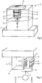
- FIG. 1 shows a pump system 1 comprising an inlet 2 for a liquid medium to be pumped, such as water containing or not containing air or gas, and an outlet 3.
- a pump system 1 can be used, for example but not exclusively, as a drainage pump or as a pump for, inter alia, well point dewatering.
- a pump head 4 which accommodates a rotor blade 5 of a pump 6 of the non-self-starting type, such as a centrifugal pump.
- the rotor blade 5 has an eye 7 which should be below the level of the liquid, so that the pump 6 itself starts to pump the liquid, by means of the rotating rotor blade 5, to the delivery side which is provided with a non-return valve 8 and which opens into the outlet 3.
- a level regulator 9 having a top connection for an air-suction pump 10 is connected to the pump head 4.
- the level regulator 9 makes sure that any water available at the inlet 2 is drawn into the pump head 4 being under reduced pressure by the air suction pump 10 while the non-return valve 8 is usually automatically in a closed state then.
- the liquid level at the eye 7 is sufficient to enable the pump 6 to self start.
- the level regulator 9 is provided with a float chamber 11 for collecting, in said float chamber, air and/or medium from the pump head 4, and with a float 12 which floats on the medium and which contains a measure of the level of the medium in the float chamber 11.
- the level regulator 9 shown in figure 2 comprises a hollow body 13 which is connected to the air suction pump 10 and which has two or, if necessary, more walls 14 which are each provided with air holes 15 for passing air which is drawn from the space above the level of the medium in the float chamber 11 and which is drained via holes 15 in the hollow body 13 by the suction pump 10.
- holes 15 of certain dimensions in more than two of the walls 14 will be used in particular when required due to the relation between the air passage through the holes 15, the power of the vacuum pump and the volume of medium to be passed through the pipes.
- larger air holes 15 in a plurality of walls 14 at larger powers and a larger water displacement.
- the level regulator 9 also comprises a member 16 which is adequately coupled to the float 12 and which can be moved over the air holes 15 along the outside of the two or more walls 14, said member being capable of closing or opening the passage of air through the holes 15.
- a member 16 which is adequately coupled to the float 12 and which can be moved over the air holes 15 along the outside of the two or more walls 14, said member being capable of closing or opening the passage of air through the holes 15.
- the level regulator 9 may be provided with a mass and/or spring and/or damper - diagrammatically indicated by means of the letter D- arranged between the float 12 and the movable member 16.
- the manner in which the member 16 dynamically moves up and down with the level of the medium can be set, for example dependent upon the viscosity of the medium, the flow behaviour in situ and/or the sand grain content or the presence of gases or air bubbles in the medium.
- the operation of the pump system 1 is such that if there is hardly any water at the inlet 2, the float 12 is located at the bottom of the float chamber 11 and the member 16 leaves all air holes open, as a result of which the air-suction pump 10 draws air from the inlet 2 through all air holes. If the air entrains medium from the inlet 2, the pump head 4 and subsequently the float chamber 11 are filled, causing the float 12 and hence the movable member 16 to move upwards and the air holes 15 to be closed. As a result, air is no longer drawn from the float chamber 11, but the pump 6 starts by itself and pumps medium to the outlet 3 through the non-return valve 8. This continues until the supply of medium through the inlet 2 is insufficient, as a result of which the level in the float chamber 11 falls and the air-suction pump 10 again causes an underpressure of air in the pump head 4 for the purpose of drawing in new medium.
- the movable member 16 preferably can be at least partly moved elastically over the air holes 15 to be opened and/or closed.
- a member 16 which is made from a suitable lightweight synthetic resin or, for example, rubber, has been found to be fast, reliable and durable, but also, in particular, it has proved to be low-maintenance in comparison with the member according to the state of the art, which has a favourable effect on the cost price.
- the movable member 16 may be a simple curtain, such as a rolling curtain, roller blind, pleated curtain, or it may be provided with movable blinds.
- Figure 3 shows a detailed view of a movable member 13, being a roller blind 16.
- a roller blind is favourable if it rolls along the outside of one or more flat walls 14 of the hollow body 13 and over the air holes 15, in which case the body 13 is preferably box or cube-shaped, because then the curtain 16 can roll well along one or more walls 14 to open or close the holes 15.
- the curtain 16 may be movable between longitudinal guides 16-1, which are provided with flexible curtain material on either side. Between said longitudinal guides, the curtain material moves up and down with the float 12.
- the movement of the member 16 will be such that it is mainly in one of two positions. In one position all air holes 15 are open and in the other position all air holes are closed.
- FIG 3 an embodiment is shown comprising a rolling curtain 16 whose movement extends over first holes 15-1 and second holes 15-2, and wherein the diameters of at least part of the first air holes 15-1 are smaller than those of the second air holes 15-2.
- the first small holes 15-1 are located higher in the wall 14 than the second air holes 15-2.
- a loose coupling between the float 12 and the member 16 enabling the movable member 16, particularly when the float 12 moves downwards, to move downwards at a lower rate, i.e., under the effect of its own weight, independently of the movement of the float.
- a more fixed coupling D having the mass and/or spring and/or damper explained hereinabove can be used to close the air holes 15-2, 15-1.
- the float 12 presses with an upward force against the curtain or member 16 as the case may be, possibly through the coupling D, which force equals the volume of the displaced medium times the specific mass.
- the floating power of the float 12 can be kept low.
- the embodiment then enables a plurality of air holes to be controlled simultaneously by means of a relatively low self-weight of bracket and movable member 16, leading to little influence on the interplay of forces resulting from the mass of water flowing through.
- the float 12 is less subject to friction when moving up and down with the liquid level, because a slide bearing on the upper side near the control member 16 can be dispensed with.
- Such a slide bearing causes variable friction, under the influence of forces exerted on the respective axle, which leads to changing friction resulting in variable reaction times and control errors.
- an axle has been omitted as well as a fixed mechanical connection, in both opposite directions, between control member 16 and float 12.
- the float 12 closes the control member 16, but the control member 16 opens on gravity force.
- the concomitant lateral forces on the bracket, that is exerted on the transverse guide and curtain axis of the member 16, shown in fig. 2 are minimal.
- the small holes 15-1 open first and if for example four holes having a diameter of 4 mm are being applied at an underpressure of max. 900 mBar than the closing force amounts approximately 450 gram. If thereafter the remaining holes open the underpressure decreases, as a result of which the remaining larger holes 15-2 open much more easily.
Landscapes
- Engineering & Computer Science (AREA)
- Mechanical Engineering (AREA)
- General Engineering & Computer Science (AREA)
- Jet Pumps And Other Pumps (AREA)
Claims (13)
- Système de pompage (1) comprenant:- une pompe (6) qui, afin de fonctionner, nécessite un niveau minimal de milieu liquide devant être pompé dans sa tête de pompe (4), et qui comprend une valve de non-retour (8) située sur son côté de livraison (3), et- un régulateur de niveau (9) qui est relié à la tête de pompe (4) et qui comporte une connexion pour une pompe à aspiration d'air (10), ledit régulateur de niveau (9) étant muni:caractérisé en ce que le corps creux est un corps en forme de boîte (13) comprenant une pluralité de parois plates (14) comportant les trous d'air (15; 15-1, 15-2), et en ce que l'élément (16) est conçu de sorte que les trous d'air (15; 15-1, 15-2) ou au moins deux desdites parois plates (14) peuvent être fermés ou ouverts de manière simultanée.- d'une chambre de flottaison (11) dans laquelle de l'air et/ou un milieu provenant de la tête de pompe (4) est recueilli,- d'un flotteur (12) qui se déplace en haut et en bas en fonction du niveau du milieu dans la chambre de flottaison (11),- d'un corps creux (13) qui, lors de son fonctionnement, est relié à la pompe à aspiration d'air (10), ledit corps creux (13) comprenant au moins une paroi (14) qui est plate et qui comporte des trous d'air (15; 15-1, 15-2) situés entre ledit corps creux (13) et la chambre de flottaison (11), et- d'un élément (16) qui est connecté au flotteur (12) et qui peut être déplacé sur les trous d'air (15; 15-1, 15-2) le long de la partie extérieure de l'au moins une paroi (14), ledit élément (16) étant utilisé pour fermer ou pour ouvrir les trous d'air (15; 15-1, 15-2);
- Système de pompage (1) selon la revendication 1, caractérisé en ce que l'élément déplaçable (16) est au moins un élément partiellement élastique qui peut se déplacer sur les trous d'air (15; 15-1, 15-2).
- Système de pompage (1) selon la revendication 1 ou la revendication 2, caractérisé en ce que l'élément déplaçable (16) est un rideau, tel qu'un rideau à enroulement, un volet mécanique, un rideau en accordéon, ou en qu'il est muni de stores roulants.
- Système de pompage (1) selon l'une quelconque des revendications 1 à 3, caractérisé en ce que le corps en forme de boîte (13) est un cube, quatre parois (14) de celui-ci, formant des paires situées de manière opposée, sont munies desdits trous d'air (15; 15-1, 15-2), et l'élément (16) est conçu pour fermer ou ouvrir de manière simultanée les trous d'air (15; 15-1, 15-2) des quatre parois plates (14).
- Système de pompage (1) selon l'une quelconque des revendications 1 à 4, caractérisé en ce que les trous d'air (15; 15-1, 15-2) sont agencés conformément à un motif se trouvant dans l'au moins une paroi (14) du corps creux (13).
- Système de pompage (1) selon l'une quelconque des revendications 1 à 5, caractérisé en ce que l'élément déplaçable (16) se trouve sensiblement dans une des deux positions, dans lesquelles tous les trous d'air (15; 15-1, 15-2) sont ouverts ou fermés, lorsque le système de pompage (1) est en fonctionnement.
- Système de pompage (1) selon l'une quelconque des revendications 1 à 6, caractérisé en ce que les diamètres des trous d'air (15; 15-1, 15-2) sont liés à la position de l'élément déplaçable (16) le long de l'au moins une paroi (14) du corps (13).
- Système de pompage (1) selon l'une quelconque des revendications 1 à 7, caractérisé en ce que le mouvement de l'élément déplaçable (16) s'étend sur les premiers (15-1) et les seconds trous d'air (15-2), et en ce que les diamètres d'au moins une partie des premiers trous d'air (15-1) sont inférieurs à ceux des seconds trous d'air (15-2).
- Système de pompage (1) selon la revendication 8, caractérisé en ce que lorsque les trous d'air (15; 15-1, 15-2) s'ouvrent, l'élément déplaçable (16) se trouve dans une position dans laquelle, initialement, la partie susmentionnée des premiers trous d'air (15-1) comportant un diamètre plus petit est exposée au moyen de l'élément déplaçable (16).
- Système de pompage (1) selon la revendication 8 ou la revendication 9, caractérisé en ce que les premiers trous (15-1) dans la paroi (14) du corps creux (13) située dans la partie supérieure de la chambre de flottaison (11) se trouvent dans une position plus élevée que les seconds trous d'air (15-2).
- Système de pompage (1) selon l'une quelconque des revendications 1 à 10, caractérisé en ce que le régulateur de niveau (9) est équipé d'une masse et/ou d'un ressort et/ou d'un amortisseur (D) agencé entre le flotteur (12) et l'élément déplaçable, éventuellement élastique (16).
- Système de pompage (1) selon l'une quelconque des revendications 1 à 11, caractérisé en ce que le régulateur de niveau (9) est équipé d'un dispositif de couplage (D) situé entre le flotteur (12) et l'élément déplaçable, éventuellement élastique (16), permettant audit élément déplaçable (16), au moins lorsque le flotteur (12) se déplace vers le bas, de se déplacer vers le bas de manière indépendante par rapport au mouvement du flotteur (12) et sous l'effet de son propre poids.
- Système de pompage (1) selon l'une quelconque des revendications 1 à 12, caractérisé en ce que l'élément déplaçable (16) comprend du caoutchouc.
Priority Applications (1)
| Application Number | Priority Date | Filing Date | Title |
|---|---|---|---|
| PL17208932T PL3339648T3 (pl) | 2016-12-21 | 2017-12-20 | Pompa cieczy z pompą powietrza zalewającego i, pomiędzy tymi dwiema pompami, zawór sterowany pływakowo |
Applications Claiming Priority (1)
| Application Number | Priority Date | Filing Date | Title |
|---|---|---|---|
| NL2018034A NL2018034B1 (nl) | 2016-12-21 | 2016-12-21 | Lucht separator |
Publications (2)
| Publication Number | Publication Date |
|---|---|
| EP3339648A1 EP3339648A1 (fr) | 2018-06-27 |
| EP3339648B1 true EP3339648B1 (fr) | 2019-07-24 |
Family
ID=58010327
Family Applications (1)
| Application Number | Title | Priority Date | Filing Date |
|---|---|---|---|
| EP17208932.8A Active EP3339648B1 (fr) | 2016-12-21 | 2017-12-20 | Pompe à liquide avec une pompe à air d'amorçage et, entre les deux pompes, une valve actionnée par un flotteur |
Country Status (6)
| Country | Link |
|---|---|
| EP (1) | EP3339648B1 (fr) |
| DK (1) | DK3339648T3 (fr) |
| ES (1) | ES2752231T3 (fr) |
| NL (1) | NL2018034B1 (fr) |
| PL (1) | PL3339648T3 (fr) |
| PT (1) | PT3339648T (fr) |
Cited By (1)
| Publication number | Priority date | Publication date | Assignee | Title |
|---|---|---|---|---|
| WO2023068920A1 (fr) * | 2021-10-21 | 2023-04-27 | Ngui Min Chee Kenneth | Système de régulation de niveau de liquide à double soupape |
Family Cites Families (6)
| Publication number | Priority date | Publication date | Assignee | Title |
|---|---|---|---|---|
| US1943536A (en) * | 1927-05-25 | 1934-01-16 | Muller Jacques | Valve mechanism for cutting off the supply of liquid to reservoirs, casks, and other containers |
| FR740812A (fr) * | 1932-07-23 | 1933-02-01 | Perfectionnements aux systèmes comprenant une pompe hydraulique | |
| US2180173A (en) * | 1937-12-20 | 1939-11-14 | Share Barnett | Float valve for hydraulic pumping systems |
| US4029438A (en) * | 1975-10-20 | 1977-06-14 | Sloan Albert H | Well point pumping system and pump assembly therefor |
| GB1486277A (en) * | 1975-10-31 | 1977-09-21 | Selwood Ltd W | Pump intake units |
| US5957150A (en) * | 1997-03-31 | 1999-09-28 | Nelson Irrigation Corporation | Air release valve |
-
2016
- 2016-12-21 NL NL2018034A patent/NL2018034B1/nl not_active IP Right Cessation
-
2017
- 2017-12-20 PT PT172089328T patent/PT3339648T/pt unknown
- 2017-12-20 ES ES17208932T patent/ES2752231T3/es active Active
- 2017-12-20 EP EP17208932.8A patent/EP3339648B1/fr active Active
- 2017-12-20 DK DK17208932T patent/DK3339648T3/da active
- 2017-12-20 PL PL17208932T patent/PL3339648T3/pl unknown
Non-Patent Citations (1)
| Title |
|---|
| None * |
Cited By (1)
| Publication number | Priority date | Publication date | Assignee | Title |
|---|---|---|---|---|
| WO2023068920A1 (fr) * | 2021-10-21 | 2023-04-27 | Ngui Min Chee Kenneth | Système de régulation de niveau de liquide à double soupape |
Also Published As
| Publication number | Publication date |
|---|---|
| ES2752231T3 (es) | 2020-04-03 |
| NL2018034B1 (nl) | 2018-06-28 |
| PL3339648T3 (pl) | 2020-04-30 |
| PT3339648T (pt) | 2019-11-04 |
| EP3339648A1 (fr) | 2018-06-27 |
| DK3339648T3 (da) | 2019-10-28 |
Similar Documents
| Publication | Publication Date | Title |
|---|---|---|
| US4173255A (en) | Low well yield control system and method | |
| US2180173A (en) | Float valve for hydraulic pumping systems | |
| CS214808B2 (en) | Closing valve | |
| KR20150022071A (ko) | 부력장치를 통해 수심을 조절하여 선택 취수하는 부유식 취수장치 | |
| EP3339648B1 (fr) | Pompe à liquide avec une pompe à air d'amorçage et, entre les deux pompes, une valve actionnée par un flotteur | |
| CN105370967A (zh) | 一种可以实现任意水位控制的浮球阀装置 | |
| EP1624190B1 (fr) | Système de pompage | |
| US4255079A (en) | Self-priming system for pumps | |
| CN213629157U (zh) | 液位控制组件 | |
| US10289128B2 (en) | Method and arrangement for maintaining fluid flow pressure in a system at a preset, almost constant level | |
| JPH05141365A (ja) | 流体圧装置 | |
| CN202215795U (zh) | 放水器 | |
| CN112253779B (zh) | 一种双液位控制浮球导阀 | |
| JP2023056300A (ja) | 液体圧送装置 | |
| US3230965A (en) | Float actuated valve | |
| CN208349420U (zh) | 补水脱气装置用的补水系统 | |
| CN115628303B (zh) | 一种先导式气控真空机械阀 | |
| US4028011A (en) | Low well yield control system | |
| WO2020053486A1 (fr) | Pompe à fluide | |
| EP1869327B1 (fr) | Procede et systeme pour lever un liquide | |
| US1941390A (en) | Gas and liquid separator | |
| EP0010557B1 (fr) | Dispositif pour assurer le transport d'un mélange en suspension de vase et d'eau venaut d'être dragué | |
| CN112197050B (zh) | 液位控制组件 | |
| US2922433A (en) | Controls for brine supply systems | |
| CN106195414A (zh) | 一种带有缓冲装置的复合式排气阀 |
Legal Events
| Date | Code | Title | Description |
|---|---|---|---|
| PUAI | Public reference made under article 153(3) epc to a published international application that has entered the european phase |
Free format text: ORIGINAL CODE: 0009012 |
|
| STAA | Information on the status of an ep patent application or granted ep patent |
Free format text: STATUS: THE APPLICATION HAS BEEN PUBLISHED |
|
| AK | Designated contracting states |
Kind code of ref document: A1 Designated state(s): AL AT BE BG CH CY CZ DE DK EE ES FI FR GB GR HR HU IE IS IT LI LT LU LV MC MK MT NL NO PL PT RO RS SE SI SK SM TR |
|
| AX | Request for extension of the european patent |
Extension state: BA ME |
|
| STAA | Information on the status of an ep patent application or granted ep patent |
Free format text: STATUS: REQUEST FOR EXAMINATION WAS MADE |
|
| 17P | Request for examination filed |
Effective date: 20181128 |
|
| RBV | Designated contracting states (corrected) |
Designated state(s): AL AT BE BG CH CY CZ DE DK EE ES FI FR GB GR HR HU IE IS IT LI LT LU LV MC MK MT NL NO PL PT RO RS SE SI SK SM TR |
|
| GRAP | Despatch of communication of intention to grant a patent |
Free format text: ORIGINAL CODE: EPIDOSNIGR1 |
|
| STAA | Information on the status of an ep patent application or granted ep patent |
Free format text: STATUS: GRANT OF PATENT IS INTENDED |
|
| GRAS | Grant fee paid |
Free format text: ORIGINAL CODE: EPIDOSNIGR3 |
|
| GRAA | (expected) grant |
Free format text: ORIGINAL CODE: 0009210 |
|
| STAA | Information on the status of an ep patent application or granted ep patent |
Free format text: STATUS: THE PATENT HAS BEEN GRANTED |
|
| INTG | Intention to grant announced |
Effective date: 20190531 |
|
| AK | Designated contracting states |
Kind code of ref document: B1 Designated state(s): AL AT BE BG CH CY CZ DE DK EE ES FI FR GB GR HR HU IE IS IT LI LT LU LV MC MK MT NL NO PL PT RO RS SE SI SK SM TR |
|
| REG | Reference to a national code |
Ref country code: GB Ref legal event code: FG4D |
|
| REG | Reference to a national code |
Ref country code: CH Ref legal event code: EP |
|
| REG | Reference to a national code |
Ref country code: DE Ref legal event code: R096 Ref document number: 602017005544 Country of ref document: DE |
|
| REG | Reference to a national code |
Ref country code: AT Ref legal event code: REF Ref document number: 1158507 Country of ref document: AT Kind code of ref document: T Effective date: 20190815 |
|
| REG | Reference to a national code |
Ref country code: IE Ref legal event code: FG4D |
|
| REG | Reference to a national code |
Ref country code: DK Ref legal event code: T3 Effective date: 20191025 |
|
| REG | Reference to a national code |
Ref country code: PT Ref legal event code: SC4A Ref document number: 3339648 Country of ref document: PT Date of ref document: 20191104 Kind code of ref document: T Free format text: AVAILABILITY OF NATIONAL TRANSLATION Effective date: 20191023 |
|
| REG | Reference to a national code |
Ref country code: SE Ref legal event code: TRGR |
|
| REG | Reference to a national code |
Ref country code: NL Ref legal event code: FP |
|
| REG | Reference to a national code |
Ref country code: LT Ref legal event code: MG4D |
|
| PG25 | Lapsed in a contracting state [announced via postgrant information from national office to epo] |
Ref country code: LT Free format text: LAPSE BECAUSE OF FAILURE TO SUBMIT A TRANSLATION OF THE DESCRIPTION OR TO PAY THE FEE WITHIN THE PRESCRIBED TIME-LIMIT Effective date: 20190724 Ref country code: FI Free format text: LAPSE BECAUSE OF FAILURE TO SUBMIT A TRANSLATION OF THE DESCRIPTION OR TO PAY THE FEE WITHIN THE PRESCRIBED TIME-LIMIT Effective date: 20190724 Ref country code: BG Free format text: LAPSE BECAUSE OF FAILURE TO SUBMIT A TRANSLATION OF THE DESCRIPTION OR TO PAY THE FEE WITHIN THE PRESCRIBED TIME-LIMIT Effective date: 20191024 Ref country code: NO Free format text: LAPSE BECAUSE OF FAILURE TO SUBMIT A TRANSLATION OF THE DESCRIPTION OR TO PAY THE FEE WITHIN THE PRESCRIBED TIME-LIMIT Effective date: 20191024 Ref country code: HR Free format text: LAPSE BECAUSE OF FAILURE TO SUBMIT A TRANSLATION OF THE DESCRIPTION OR TO PAY THE FEE WITHIN THE PRESCRIBED TIME-LIMIT Effective date: 20190724 |
|
| PG25 | Lapsed in a contracting state [announced via postgrant information from national office to epo] |
Ref country code: RS Free format text: LAPSE BECAUSE OF FAILURE TO SUBMIT A TRANSLATION OF THE DESCRIPTION OR TO PAY THE FEE WITHIN THE PRESCRIBED TIME-LIMIT Effective date: 20190724 Ref country code: GR Free format text: LAPSE BECAUSE OF FAILURE TO SUBMIT A TRANSLATION OF THE DESCRIPTION OR TO PAY THE FEE WITHIN THE PRESCRIBED TIME-LIMIT Effective date: 20191025 Ref country code: IS Free format text: LAPSE BECAUSE OF FAILURE TO SUBMIT A TRANSLATION OF THE DESCRIPTION OR TO PAY THE FEE WITHIN THE PRESCRIBED TIME-LIMIT Effective date: 20191124 Ref country code: AL Free format text: LAPSE BECAUSE OF FAILURE TO SUBMIT A TRANSLATION OF THE DESCRIPTION OR TO PAY THE FEE WITHIN THE PRESCRIBED TIME-LIMIT Effective date: 20190724 Ref country code: LV Free format text: LAPSE BECAUSE OF FAILURE TO SUBMIT A TRANSLATION OF THE DESCRIPTION OR TO PAY THE FEE WITHIN THE PRESCRIBED TIME-LIMIT Effective date: 20190724 |
|
| PGFP | Annual fee paid to national office [announced via postgrant information from national office to epo] |
Ref country code: LU Payment date: 20191227 Year of fee payment: 3 |
|
| PG25 | Lapsed in a contracting state [announced via postgrant information from national office to epo] |
Ref country code: TR Free format text: LAPSE BECAUSE OF FAILURE TO SUBMIT A TRANSLATION OF THE DESCRIPTION OR TO PAY THE FEE WITHIN THE PRESCRIBED TIME-LIMIT Effective date: 20190724 |
|
| PG25 | Lapsed in a contracting state [announced via postgrant information from national office to epo] |
Ref country code: EE Free format text: LAPSE BECAUSE OF FAILURE TO SUBMIT A TRANSLATION OF THE DESCRIPTION OR TO PAY THE FEE WITHIN THE PRESCRIBED TIME-LIMIT Effective date: 20190724 Ref country code: RO Free format text: LAPSE BECAUSE OF FAILURE TO SUBMIT A TRANSLATION OF THE DESCRIPTION OR TO PAY THE FEE WITHIN THE PRESCRIBED TIME-LIMIT Effective date: 20190724 |
|
| PG25 | Lapsed in a contracting state [announced via postgrant information from national office to epo] |
Ref country code: SM Free format text: LAPSE BECAUSE OF FAILURE TO SUBMIT A TRANSLATION OF THE DESCRIPTION OR TO PAY THE FEE WITHIN THE PRESCRIBED TIME-LIMIT Effective date: 20190724 Ref country code: SK Free format text: LAPSE BECAUSE OF FAILURE TO SUBMIT A TRANSLATION OF THE DESCRIPTION OR TO PAY THE FEE WITHIN THE PRESCRIBED TIME-LIMIT Effective date: 20190724 Ref country code: CZ Free format text: LAPSE BECAUSE OF FAILURE TO SUBMIT A TRANSLATION OF THE DESCRIPTION OR TO PAY THE FEE WITHIN THE PRESCRIBED TIME-LIMIT Effective date: 20190724 Ref country code: IS Free format text: LAPSE BECAUSE OF FAILURE TO SUBMIT A TRANSLATION OF THE DESCRIPTION OR TO PAY THE FEE WITHIN THE PRESCRIBED TIME-LIMIT Effective date: 20200224 |
|
| REG | Reference to a national code |
Ref country code: DE Ref legal event code: R097 Ref document number: 602017005544 Country of ref document: DE |
|
| PLBE | No opposition filed within time limit |
Free format text: ORIGINAL CODE: 0009261 |
|
| STAA | Information on the status of an ep patent application or granted ep patent |
Free format text: STATUS: NO OPPOSITION FILED WITHIN TIME LIMIT |
|
| PG2D | Information on lapse in contracting state deleted |
Ref country code: IS |
|
| 26N | No opposition filed |
Effective date: 20200603 |
|
| PG25 | Lapsed in a contracting state [announced via postgrant information from national office to epo] |
Ref country code: SI Free format text: LAPSE BECAUSE OF FAILURE TO SUBMIT A TRANSLATION OF THE DESCRIPTION OR TO PAY THE FEE WITHIN THE PRESCRIBED TIME-LIMIT Effective date: 20190724 Ref country code: MC Free format text: LAPSE BECAUSE OF FAILURE TO SUBMIT A TRANSLATION OF THE DESCRIPTION OR TO PAY THE FEE WITHIN THE PRESCRIBED TIME-LIMIT Effective date: 20190724 |
|
| PG25 | Lapsed in a contracting state [announced via postgrant information from national office to epo] |
Ref country code: IE Free format text: LAPSE BECAUSE OF NON-PAYMENT OF DUE FEES Effective date: 20191220 |
|
| REG | Reference to a national code |
Ref country code: AT Ref legal event code: UEP Ref document number: 1158507 Country of ref document: AT Kind code of ref document: T Effective date: 20190724 |
|
| PG25 | Lapsed in a contracting state [announced via postgrant information from national office to epo] |
Ref country code: CY Free format text: LAPSE BECAUSE OF FAILURE TO SUBMIT A TRANSLATION OF THE DESCRIPTION OR TO PAY THE FEE WITHIN THE PRESCRIBED TIME-LIMIT Effective date: 20190724 |
|
| PG25 | Lapsed in a contracting state [announced via postgrant information from national office to epo] |
Ref country code: HU Free format text: LAPSE BECAUSE OF FAILURE TO SUBMIT A TRANSLATION OF THE DESCRIPTION OR TO PAY THE FEE WITHIN THE PRESCRIBED TIME-LIMIT; INVALID AB INITIO Effective date: 20171220 Ref country code: MT Free format text: LAPSE BECAUSE OF FAILURE TO SUBMIT A TRANSLATION OF THE DESCRIPTION OR TO PAY THE FEE WITHIN THE PRESCRIBED TIME-LIMIT Effective date: 20190724 |
|
| REG | Reference to a national code |
Ref country code: CH Ref legal event code: PL |
|
| PG25 | Lapsed in a contracting state [announced via postgrant information from national office to epo] |
Ref country code: LU Free format text: LAPSE BECAUSE OF NON-PAYMENT OF DUE FEES Effective date: 20201220 |
|
| PG25 | Lapsed in a contracting state [announced via postgrant information from national office to epo] |
Ref country code: LI Free format text: LAPSE BECAUSE OF NON-PAYMENT OF DUE FEES Effective date: 20201231 Ref country code: CH Free format text: LAPSE BECAUSE OF NON-PAYMENT OF DUE FEES Effective date: 20201231 |
|
| PG25 | Lapsed in a contracting state [announced via postgrant information from national office to epo] |
Ref country code: MK Free format text: LAPSE BECAUSE OF FAILURE TO SUBMIT A TRANSLATION OF THE DESCRIPTION OR TO PAY THE FEE WITHIN THE PRESCRIBED TIME-LIMIT Effective date: 20190724 |
|
| PGFP | Annual fee paid to national office [announced via postgrant information from national office to epo] |
Ref country code: DE Payment date: 20251211 Year of fee payment: 9 |
|
| PGFP | Annual fee paid to national office [announced via postgrant information from national office to epo] |
Ref country code: GB Payment date: 20251219 Year of fee payment: 9 |
|
| PGFP | Annual fee paid to national office [announced via postgrant information from national office to epo] |
Ref country code: PT Payment date: 20251211 Year of fee payment: 9 Ref country code: AT Payment date: 20251222 Year of fee payment: 9 |
|
| PGFP | Annual fee paid to national office [announced via postgrant information from national office to epo] |
Ref country code: IT Payment date: 20251223 Year of fee payment: 9 Ref country code: DK Payment date: 20251224 Year of fee payment: 9 |
|
| PGFP | Annual fee paid to national office [announced via postgrant information from national office to epo] |
Ref country code: FR Payment date: 20251229 Year of fee payment: 9 Ref country code: NL Payment date: 20251219 Year of fee payment: 9 |
|
| PGFP | Annual fee paid to national office [announced via postgrant information from national office to epo] |
Ref country code: BE Payment date: 20251219 Year of fee payment: 9 |
|
| PGFP | Annual fee paid to national office [announced via postgrant information from national office to epo] |
Ref country code: SE Payment date: 20251219 Year of fee payment: 9 |
|
| PGFP | Annual fee paid to national office [announced via postgrant information from national office to epo] |
Ref country code: PL Payment date: 20251216 Year of fee payment: 9 |
|
| PGFP | Annual fee paid to national office [announced via postgrant information from national office to epo] |
Ref country code: ES Payment date: 20260130 Year of fee payment: 9 |