EP3339726A1 - Glace de projecteur automobile avec électrodes thermoplastiques surmoulées - Google Patents
Glace de projecteur automobile avec électrodes thermoplastiques surmoulées Download PDFInfo
- Publication number
- EP3339726A1 EP3339726A1 EP17205677.2A EP17205677A EP3339726A1 EP 3339726 A1 EP3339726 A1 EP 3339726A1 EP 17205677 A EP17205677 A EP 17205677A EP 3339726 A1 EP3339726 A1 EP 3339726A1
- Authority
- EP
- European Patent Office
- Prior art keywords
- ice
- electrodes
- electrically conductive
- electrode
- conductive coating
- Prior art date
- Legal status (The legal status is an assumption and is not a legal conclusion. Google has not performed a legal analysis and makes no representation as to the accuracy of the status listed.)
- Granted
Links
Images
Classifications
-
- F—MECHANICAL ENGINEERING; LIGHTING; HEATING; WEAPONS; BLASTING
- F21—LIGHTING
- F21V—FUNCTIONAL FEATURES OR DETAILS OF LIGHTING DEVICES OR SYSTEMS THEREOF; STRUCTURAL COMBINATIONS OF LIGHTING DEVICES WITH OTHER ARTICLES, NOT OTHERWISE PROVIDED FOR
- F21V29/00—Protecting lighting devices from thermal damage; Cooling or heating arrangements specially adapted for lighting devices or systems
- F21V29/90—Heating arrangements
-
- F—MECHANICAL ENGINEERING; LIGHTING; HEATING; WEAPONS; BLASTING
- F21—LIGHTING
- F21S—NON-PORTABLE LIGHTING DEVICES; SYSTEMS THEREOF; VEHICLE LIGHTING DEVICES SPECIALLY ADAPTED FOR VEHICLE EXTERIORS
- F21S41/00—Illuminating devices specially adapted for vehicle exteriors, e.g. headlamps
- F21S41/20—Illuminating devices specially adapted for vehicle exteriors, e.g. headlamps characterised by refractors, transparent cover plates, light guides or filters
- F21S41/28—Cover glass
-
- F—MECHANICAL ENGINEERING; LIGHTING; HEATING; WEAPONS; BLASTING
- F21—LIGHTING
- F21S—NON-PORTABLE LIGHTING DEVICES; SYSTEMS THEREOF; VEHICLE LIGHTING DEVICES SPECIALLY ADAPTED FOR VEHICLE EXTERIORS
- F21S45/00—Arrangements within vehicle lighting devices specially adapted for vehicle exteriors, for purposes other than emission or distribution of light
- F21S45/60—Heating of lighting devices, e.g. for demisting
-
- H—ELECTRICITY
- H05—ELECTRIC TECHNIQUES NOT OTHERWISE PROVIDED FOR
- H05B—ELECTRIC HEATING; ELECTRIC LIGHT SOURCES NOT OTHERWISE PROVIDED FOR; CIRCUIT ARRANGEMENTS FOR ELECTRIC LIGHT SOURCES, IN GENERAL
- H05B3/00—Ohmic-resistance heating
- H05B3/84—Heating arrangements specially adapted for transparent or reflecting areas, e.g. for demisting or de-icing windows, mirrors or vehicle windshields
Definitions
- the invention relates to the field of lighting and light signaling, particularly for motor vehicles. More specifically, the invention relates to the field of light devices, including motor vehicle, comprising a housing and a closing window of said housing.
- the published patent document US 2014/0332518 A1 discloses a motor vehicle headlamp glazing, comprising on its inner face an electrically conductive coating for use as an electrical ice-defrosting resistor. To do this, the coating forms one or more metal tracks deposited on the ice.
- Metal electrodes are arranged at two opposite ends of the region of the metal tracks so as to allow a homogeneous distribution of the feed stream for the deicing to the different tracks.
- the electrodes are fixed and connected to the metal tracks by soldering or by a conductive adhesive. Each of these electrodes is remote from the edges of the ice and is intended to be connected to a power supply. This teaching, however, does not specify how this connection is made.
- the published patent document DE 20 2012 005 908 U also discloses a searchlight for a motor vehicle.
- the ice includes, on its outer face this time, an electrically conductive coating for forming an electric defrosting resistance of said ice.
- the coating forms a seemingly continuous layer comprising carbon nanotubes.
- a protective varnish is deposited on the electrically conductive coating to protect it.
- the electrical connection of the electrically conductive coating is not detailed in this teaching.
- this teaching is specifically limited to a conductive coating electrically disposed on the outer face of the ice, for its defrost in winter.
- the published patent document US 2007/0181565 A1 discloses, similarly to the aforementioned documents, a motor vehicle headlamp, comprising an electrically conductive coating for forming an electric defrosting resistance of said ice.
- the coating includes a Electrically conductive track forming zigzags.
- the tracks end with a connector disposed on the inner face of a return portion of the ice.
- a plug can then be connected to the connector for powering the defrost heater.
- This teaching is interesting in that it provides the necessary measures for the electrical connection of the defrosting resistor. These measurements are, however, limited to an electric resistance in the form of a track forming zigzags and ending in two endings to be fed. These tracks are usually visible.
- the connector requires the presence of a return portion of the ice and the connection is necessarily inside the housing.
- the object of the invention is to propose a solution that overcomes at least one drawback of the state of the art, more particularly of the state of the art mentioned above. More specifically, the invention aims to provide a deicing solution of a luminous device ice that is efficient, economical and practical.
- the subject of the invention is a luminous device window, in particular a motor vehicle, comprising: a main portion made of transparent plastic material; at least two fixing edges to a housing of the light device; an electrically conductive coating forming a defrosting electrical resistance; at least two electrodes electrically connected to the conductive coating; remarkable in that the electrodes are electrically conductive thermoplastic material and located on the fixing edges.
- edges comprising the electrodes may be upper and lower edges and / or side edges.
- the electrodes can ensure the ice contact with the housing.
- the electrodes are overmolded by the transparent plastic material.
- each of the electrodes comprises a connector intended to provide a power supply.
- each of the connectors comprises at least one electrical pin protruding from the electrode comprising said connector, and an engagement device with a plug, said device being made of electrically insulating material and said pin or pins. being overmolded by the material of the electrode so as to be electrically connected to said electrode.
- the electrical pin or pins advantageously extend in the material of the electrodes.
- each of the engagement devices comprises a ring surrounding the corresponding pin or pins, said ring comprising means of mechanical engagement with the plug.
- the material of the electrodes comprises a polymer matrix of the thermoplastic resin type, preferably polycarbonate, and an electrically conductive filler material, preferably of the fiber, resin and / or particle type.
- thermoplastic resin is chosen from the group comprising: polycarbonate, polyamide, polyethylene, polyethylene terephthalate, polybutylene terephthalate, polyphthalamide, polyacrylic acid.
- the fillers are chosen from the group comprising: nano particles, zinc sulphide, carbon-based particles, copper and copper alloy (brass)
- each of the engagement devices is overmolded on the corresponding electrode.
- the material of the electrodes has a surface resistivity of less than or equal to 10 4 ⁇ / cm 2 .
- the electrically conductive coating covers the electrodes, preferably on an inner face of said ice.
- the overlap extends over 80% of the length of the electrode.
- the electrically conductive coating is a varnish comprising metal oxides, preferably transparent metal oxides, with a transmission coefficient of at least 90% in wavelengths of the visible range, which conductors are composed of the following oxides, taken alone or in combination from: zinc oxide doped with aluminum AZO; indium tin oxide ITO; zirconium oxide ZrO2; tantalum oxide Ta2O5; tin oxide doped with ATO antimony. oxides of indium and tin.
- the electrically conductive coating is based on electrically conductive organic material, in particular phenylene polysulfide or Pedot: PSS. It is recalled that Pedot: Pss is a mixture of two polymers which are poly (3,4-ethylenedioxythiophene) (PEDOT); and sodium polystyrene sulfonate (PSS).
- the electrically conductive coating forms a continuous film covering at least 30% of the surface of the main portion of the ice.
- each of the electrodes extends over at least 25% of the length of the edge comprising it.
- each of the electrodes extends over the thickness of the transparent plastic material adjacent to said electrode.
- each of the electrodes has a profile with a projection in contact, by cohesion, with the transparent material.
- the invention also relates to a light device, especially a motor vehicle, comprising: a housing forming an open cavity; an ice attached to the housing and closing the cavity; at least one light module in the cavity; remarkable in that the ice is in accordance with the invention.
- the device is advantageously a projector.
- the subject of the invention is also a process for producing a luminous device glazing, in particular for a motor vehicle, which is remarkable in that the glass is according to the invention and the following stages: (a) injection of the transparent plastic material into a mold; (b) injecting the electrically conductive thermoplastic material into the mold for producing the electrodes (10).
- step (b) is performed while the transparent plastic material is solidified.
- the two injection stages have reversed.
- the measures of the invention are interesting in that they make it possible to perform efficiently and economically the power supply of the ice defrosting function of a light device. Indeed, the fact of placing the electrodes at the fixing edges has a first advantage of arranging them in areas not visible from the outside. Similarly, in the context of two-colored windows, with transparent central zone and opaque peripheral collar, the electrodes are located in the opaque zone.
- This also has a second advantage of being able to make an electrical connection to the outside of the device.
- the connectors and connection plugs can then be arranged outside the visible zone from the outside.
- the fact of making the electrodes of thermoplastic material makes it possible to produce them by injection during the injection of the transparent material. The cost of producing the ice can then be reduced.
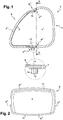
- the Figures 1 and 2 illustrate an exemplary embodiment of a light device according to the invention.
- the figure 1 is a vertical longitudinal sectional view when the device is in the normal mounting position on a vehicle.
- the figure 2 is a view along section II-II.
- the light device 2 comprises a housing 4 forming a cavity 4 1 with an open, said opening being covered by the window 6.
- the housing 4 is preferably made of plastic material. It may consist of several elements attached to each other.
- the ice is transparent and advantageously made of plastic such as polycarbonate (PC).
- the glass 6 comprises a main portion 6 1 intended to be traversed by the light rays of one or more light modules disposed in the cavity of the housing 4. It also comprises upper and lower edges 6 2 intended to cooperate with corresponding edges 4 2 of the housing 4.
- the main portion 6 1 of the ice 6 comprises, advantageously on its inner face, an electrically conductive coating 8, capable of forming an electrical resistance for defrosting and / or defogging the ice 6.
- This coating is advantageously a continuous coating in the form of a varnish comprising an electrically conductive filler material, such as, for example, indium-tin oxides.
- Indium tin oxide indium tin oxide or indium tin oxide
- Indium tin oxide is a mixture of indium (III) oxide (In 2 O 3 ) and tin oxide (IV) (SnO 2 ), in the typical weight ratio of 90% of the first and 10% of the second. This compound is colorless and transparent in thin layers.
- the main characteristic of indium-tin oxide is its combination of electrical conductivity and optical transparency.
- Other conductive filler materials can be envisaged.
- the varnish advantageously comprises a transparent polymer matrix based on acrylic; or polyester-based; or based on polymers such as polycarbonate.
- the electrically conductive coating has a thermal conductivity greater than 10 Wm -1 .K -1 .
- Thermal conductivity is the amount of heat transferred per unit area and time under a temperature gradient of 1 kelvin per meter.
- It may be deposited with a thickness of between 1 and 5 ⁇ m, preferably between 2 and 3 ⁇ m.
- the glass 6 comprises upper and lower edges 6 2 cooperating with the corresponding edges 4 2 of the casing 4. These upper and lower edges 6 2 comprise electrodes 10 embedded in the plastic material forming the glass 6. It can also be observed that the electrically conductive coating 8 extends vertically to cover the electrodes 10. The latter are indeed positioned at the edges 6 2 so as to freely present their internal faces, the latter can then be in contact direct with the electrically conductive coating 8.
- the electrodes are made of electrically conductive thermoplastic material.
- This material may comprise a thermoplastic matrix, such as in particular polycarbonate (PC) or high-density polyethylene (PE-HD), and a charging material providing electrical conduction, such as in particular carbon black.
- the filler material may also be a resin or fibers.
- Their surface resistivity may be between 10 1 and 10 4 ⁇ / cm 2 .
- ESD C 1002 from the company RTP®.
- This material comprises a base of polybutylene terephthalate (PBT) and glass fibers. It has a surface resistivity of less than 10 6 ⁇ / cm 2 .
- PRE-ELEC® PE 1202 from PREMlX®.
- the electrode 10 has a section with a profile with a projection on which the transparent plastic material is overmolded.
- a connector 12 + 14 is disposed on the electrode 10. It comprises one or more electrical pins 12 protruding from the electrode 10 and electrically connected with said electrode 10. It also comprises a device 14 for engagement with a plug (no shown).
- the latter may be formed by an annular wall of insulating material and overmolded on the electrode 10. The annular wall surrounds the pins 12. Mechanical engagement means may be provided on the annular wall, in order to ensure a retention of the card (not shown).
- the connector is disposed on its inner face unlike that of the lower edge which is on the outer face of the electrode.
- the connector can be arranged, optionally, on the inner face or on the outer face of the electrode.
- the figure 2 is a view according to section II-II of the figure 1 , That is to say a rear view of the mirror 6. It can be seen the extent of the conductive coating 8 on substantially the entire width of the ice, since one of the upper and lower edges 6 2 to the opposite edge 6 2 . It can also be observed that each electrode 10 extends transversely along the corresponding edge 6 2 .
- the electrodes 10 are arranged on the upper and lower edges 6 2 , so as to generate a current in a substantially vertical direction along the conductive coating 8.
- the electrodes 10 may, alternatively or additionally, be arranged on the side edges 6 3 .
- the current flowing through the conductive coating 10 will be oriented substantially horizontally.
- different configurations of the electrodes are possible on the edges 6 2 and 6 3 , provided that they make it possible to circulate a current along the conductive coating 8.
- the realization of the ice which has just been described can be carried out as follows.
- the electrically conductive material is first injected into the zone or zones corresponding to the electrodes.
- the mold is then configured to inject material into the remaining area corresponding to the remainder of the ice.
- the transparent material is then injected into the mold, thus covering and overmolding the electrodes.
- the transparent material is injected first and then the electrodes are injected when they are dasn an opaque dyed polymer.
- the second injection is performed while the material of the first injection is solidified to ensure optimal cohesion between the two materials.
- the injection may comprise an additional step of injecting the engagement device with a plug of the connector.
- This device is advantageously of electrically insulating material, that is to say different from that of the electrodes.
- This additional injection step can then take place after the injection of the electrically conductive material. It can be done before, during or after the injection of the transparent material.
- the electrically conductive coating is then applied outside the mold, in particular by spraying or spraying.
Landscapes
- Engineering & Computer Science (AREA)
- General Engineering & Computer Science (AREA)
- Non-Portable Lighting Devices Or Systems Thereof (AREA)
- Resistance Heating (AREA)
- Compositions Of Macromolecular Compounds (AREA)
Abstract
Description
- L'invention a trait au domaine de l'éclairage et de la signalisation lumineuse, notamment pour les véhicules automobiles. Plus précisément, l'invention a trait au domaine des dispositifs lumineux, notamment de véhicule automobile, comprenant un boîtier et une glace de fermeture dudit boîtier.
- Le document de brevet publié
US 2014/0332518 A1 divulgue une glace de projecteur de véhicule automobile, comprenant sur sa face intérieure un revêtement conducteur électriquement destiné à servir de résistance électrique de dégivrage de la glace. Pour ce faire, le revêtement forme une ou plusieurs pistes métalliques déposées sur la glace. Des électrodes métalliques sont disposées à deux extrémités opposées de la zone des pistes métalliques de manière à permettre une distribution homogène du courant d'alimentation pour le dégivrage vers les différentes pistes. Les électrodes sont fixées et connectées aux pistes métalliques par brasure ou par un adhésif conducteur. Chacune de ces électrodes est à distance des bords de la glace et est destinée à être connectée à une alimentation électrique. Cet enseignement ne précise cependant pas de quelle manière cette connexion est réalisée. - Le document de brevet publié
DE 20 2012 005 908 U divulgue également une glace de projecteur pour véhicule automobile. La glace comprend, sur sa face extérieure cette fois-ci, un revêtement conducteur électriquement en vue de former une résistance électrique de dégivrage de ladite glace. Le revêtement forme une couche en apparence continue et comprenant des nanotubes de carbone. Un vernis de protection est déposé sur le revêtement conducteur électriquement en vue de le protéger. Le raccordement électrique du revêtement conducteur électriquement n'est pas détaillé dans cet enseignement. De plus, cet enseignement se limite spécifiquement à un revêtement conducteur électriquement disposé sur la face extérieure de la glace, en vue de son dégivrage en hiver. - Le document de brevet publié
US 2007/0181565 A1 divulgue, similairement aux documents susmentionnés, une glace de projecteur pour véhicule automobile, comprenant un revêtement conducteur électriquement en vue de former une résistance électrique de dégivrage de ladite glace. Le revêtement comprend une piste conductrice électriquement formant des zigzags. Les pistes se terminent par un connecteur disposé sur la face intérieure d'une portion de renvoi de la glace. Une fiche peut alors être connectée au connecteur en vue de l'alimentation électrique de la résistance de dégivrage. Cet enseignement est intéressant en ce qu'il prévoit les mesures nécessaires au branchement électrique de la résistance de dégivrage. Ces mesures sont toutefois limitées à une résistance électrique sous forme de piste formant des zigzags et se terminant par deux terminaisons à alimenter. Ces pistes sont généralement visibles. De plus, le connecteur requiert la présence d'une portion de renvoi de la glace et le branchement se fait nécessairement à l'intérieur du boîtier. - L'invention a pour objectif de proposer une solution palliant au moins un inconvénient de l'état de l'art, plus particulièrement de l'état de l'art susmentionné. Plus précisément encore, l'invention a pour objectif de proposer une solution de dégivrage d'une glace de dispositif lumineux qui soit performante, économique et pratique.
- L'invention a pour objet une glace de dispositif lumineux, notamment de véhicule automobile, comprenant : une portion principale en matériau plastique transparent ; au moins deux bords de fixation à un boîtier du dispositif lumineux ; un revêtement conducteur électriquement formant une résistance électrique de dégivrage ; au moins deux électrodes reliées électriquement au revêtement conducteur ; remarquable en ce que les électrodes sont en matériau thermoplastique conducteur électriquement et situées sur les bords de fixation.
- Les bords comprenant les électrodes peuvent être des bords supérieur et inférieur et/ou des bords latéraux.
- Les électrodes peuvent assurer le contact de la glace avec le boîtier.
- Selon un mode avantageux de l'invention, les électrodes sont surmoulées par le matériau plastique transparent.
- Selon un mode avantageux de l'invention, chacune des électrodes comprend un connecteur destiné à assurer une alimentation électrique.
- Selon un mode avantageux de l'invention, chacun des connecteurs comprend au moins une broche électrique faisant saillie de l'électrode comprenant ledit connecteur, et un dispositif d'engagement avec une fiche, ledit dispositif étant en matériau isolant électrique et ladite ou lesdites broches étant surmoulées par le matériau de l'électrode de manière être reliées électriquement avec ladite électrode. La ou les broches électriques s'étendent avantageusement dans le matériau des électrodes.
- Selon un mode avantageux de l'invention, chacun des dispositifs d'engagement comprend un anneau entourant la ou les broches correspondantes, ledit anneau comprenant des moyens d'engagement mécanique avec la fiche.
- Selon un mode avantageux de l'invention, le matériau des électrodes comprend une matrice polymère de type résine thermoplastique, préférentiellement du polycarbonate, et un matériau de charge conducteur électriquement, préférentiellement du type fibres, résine et/ou particules.
- En particulier, la résine thermoplastique est choisie dans le groupe comprenant : polycarbonate, polyamide, polyéthylène, polyéthylène téréphtalate, polybutylène téréphtalate, polyphtalamide, poly(acide acrylique).
- En particulier, les charges sont choisies dans le groupe comprenant : nano particules, sulfure de zinc, particules à base de carbone, cuivre et alliage de cuivre (laiton)
- Selon un mode avantageux de l'invention, chacun des dispositifs d'engagement est surmoulé sur l'électrode correspondante.
- Selon un mode avantageux de l'invention, le matériau des électrodes présente une résistivité de surface inférieure ou égale à 104 Ω/cm2.
- Selon un mode avantageux de l'invention, le revêtement conducteur électriquement recouvre les électrodes, préférentiellement sur une face intérieure de ladite glace. Le recouvrement s'étend sur plus de 80% de la longueur de l'électrode.
- Selon un mode avantageux de l'invention, le revêtement conducteur électrique est un vernis comprenant des oxydes métalliques, préférentiellement des oxydes métalliques transparents, avec un coefficient de transmission d'au moins 90% dans les longueurs d'ondes du domaine visible, conducteurs qui sont composés des oxydes suivants, pris seuls ou en combinaison parmi : oxyde de zinc dopé à l'aluminium AZO ; oxyde d'indium étain ITO ; oxyde de zirconium ZrO2 ; oxyde de tantale Ta2O5 ; oxyde d'étain dopé à l'antimoine ATO. oxydes d'indium et d'étain. Alternativement, le revêtement conducteur électrique est à base de matière organique électriquement conductrice, notamment du polysulfure de phénylène ou du Pedot :PSS. On rappelle que le Pedot:Pss est un mélange de deux polymères qui sont le poly(3,4-éthylènedioxythiophène) (PEDOT) ; et le poly(styrène sulfonate) de sodium (PSS).
- Avantageusement, le revêtement conducteur électriquement forme un film continu recouvrant au moins 30% de la surface de la portion principale de la glace.
- On notera que le revêtement couvre de préférence toute l'étendue de la surface intérieure de la glace transparente. il peut aussi n'est couvrir qu'une partie :
- si la forme de la glace empêche de réaliser le dépôt dans certaines zones, en fonction des techniques de dépôt retenues ;
- si l'on souhaite restreindre le dépôt aux zones de la glace dans lesquelles le phénomène de condensation se produit en situation de fonctionnement réel du dispositif d'éclairage et/ou signalisation auquel est destinée ladite glace, zones pouvant être déterminées par simulation thermique ou par observation lors des phases de mise au point du dispositif d'éclairage et du véhicule dans lequel il est intégré.
- Selon un mode avantageux de l'invention, chacune des électrodes s'étend sur au moins 25% de la longueur du bord la comprenant.
- Selon un mode avantageux de l'invention, chacune des électrodes s'étend sur l'épaisseur du matériau plastique transparent adjacent à ladite électrode.
- Avantageusement, chacune des électrodes présente un profil avec un ressaut en contact, par cohésion, avec le matériau transparent.
- L'invention a également pour objet un dispositif lumineux, notamment de véhicule automobile, comprenant : un boîtier formant une cavité ouverte ; une glace fixée au boîtier et refermant la cavité ; au moins un module lumineux dans la cavité ; remarquable en ce que la glace est conforme à l'invention. Le dispositif est avantageusement un projecteur.
- L'invention a également pour objet un procédé de réalisation d'une glace de dispositif lumineux, notamment de véhicule automobile, remarquable en ce que la glace est selon l'invention et par les étapes suivantes : (a) injection du matériau plastique transparent dans un moule; (b) injection du matériau thermoplastique conducteur électriquement dans le moule en vue de réaliser les électrodes (10).
- Selon un mode avantageux de l'invention, l'étape (b) est réalisée alors que le matériau plastique transparent est solidifié.
- Selon une variante, les deux étapes d'injection ont inversées.
- Les mesures de l'invention sont intéressantes en ce qu'elles permettent de réaliser de manière performante et économique l'alimentation électrique de la fonction de dégivrage de la glace d'un dispositif lumineux. En effet, le fait de placer les électrodes au niveau des bords de fixation présente un premier avantage de les disposer dans des zones non visibles depuis l'extérieur. De même, dans le cadre de glaces bicolore, avec zone centrale transparente et collerette périphérique opaque, les électrodes sont situées dans la zone opaque.
- Cela présente également un deuxième avantage de pouvoir réaliser une liaison électrique vers l'extérieur du dispositif. Les connecteurs et fiches de connexion peuvent alors être disposés en dehors de la zone visible depuis l'extérieur. Le fait de réaliser les électrodes en matériau thermoplastique permet de les réaliser par injection lors de l'injection de la matière transparente. Le coût de production de la glace peut alors être réduit.
- D'autres caractéristiques et avantages de la présente invention seront mieux compris à l'aide de la description et des dessins parmi lesquels :
- La
figure 1 est une vue en coupe suivant un plan longitudinal et vertical d'un boîtier de dispositif lumineux, avec un glace conforme à l'invention ; - La
figure 2 est une vue du boîtier de lafigure 1 suivant la coupe II-II. - Les
figures 1 et 2 illustrent un exemple de réalisation d'un dispositif lumineux conforme à l'invention. Lafigure 1 est une vue en coupe longitudinale verticale lorsque le dispositif est en position normale de montage sur un véhicule. Lafigure 2 est une vue suivant la coupe II-II. - En référence à la
figure 1 , le dispositif lumineux 2 comprend un boîtier 4 formant une cavité 41 avec une ouverte, ladite ouverture étant couverte par la glace 6. Le boîtier 4 est avantageusement en matériau plastique. Il peut être constitué de plusieurs éléments fixés les uns aux autres. La glace est transparente et avantageusement réalisée en matière plastique comme notamment du polycarbonate (PC). La glace 6 comprend une portion principale 61 destinée à être traversée par les rayons lumineux d'un ou plusieurs modules lumineux disposés dans la cavité du boîtier 4. Elle comprend également des bords supérieurs et inférieurs 62 destinés à coopérer avec des bords correspondants 42 du boîtier 4. - La portion principale 61 de la glace 6 comprend, avantageusement sur sa face intérieure, un revêtement conducteur électriquement 8, apte à former une résistance électrique de dégivrage et/ou désembuage de la glace 6. Ce revêtement est avantageusement un revêtement continu sous forme d'un vernis comprenant un matériau de charge conducteur électriquement, comme par exemple des oxydes d'indium-étain. L'oxyde d'indium-étain (ou oxyde d'indium dopé à l'étain ou ITO pour l'appellation anglaise « Indium tin oxide ») est un mélange d'oxyde d'indium(III) (In2O3) et d'oxyde d'étain (IV) (SnO2), dans la proportion massique typique de 90 % du premier et 10 % du second. Ce composé est incolore et transparent en couches minces. La caractéristique principale de l'oxyde d'indium-étain est sa combinaison de conductivité électrique et de transparence optique. D'autres matériaux de charge conducteurs peuvent être envisagés. Le vernis comprend avantageusement une matrice polymère transparente à base d'acrylique ; ou à base de polyester ; ou à base de polymères comme du polycarbonate.
- Le revêtement conducteur électriquement a une conductivité thermique supérieure à 10 W.m-1.K-1. On appelle conductivité thermique, l'énergie quantité de chaleur transférée par unité de surface et de temps sous un gradient de température de 1 kelvin par mètre.
- Il peut être déposé avec une épaisseur comprise entre 1 et 5µm, préférentiellement entre 2 et 3µm.
- Toujours en relation avec la
figure 1 , on peut observer que la glace 6 comprend des bords supérieur et inférieur 62 coopérant avec des bords correspondants 42 du boîtier 4. Ces bords, supérieur et inférieur, 62 comprennent des électrodes 10 noyées dans la matière plastique formant la glace 6. On peut également observer que le revêtement conducteur électriquement 8 s'étend verticalement jusqu'à recouvrir les électrodes 10. Ces dernières sont en effet positionnées au niveau des bords 62 de manière à présenter librement leurs faces internes, ces dernières pouvant alors être en contact direct avec le revêtement conducteur électriquement 8. - Les électrodes sont réalisées en matériau thermoplastique conducteur électriquement. Ce matériau peut comprendre une matrice thermoplastique, comme notamment du polycarbonate (PC) ou du polyéthylène haute densité (PE-HD), et un matériau de charge assurant la conduction électrique, comme notamment du noir de carbone. Le matériau de charge peut également être une résine ou des fibres. De tels matériaux sont connus en soi de l'homme de métier. Leur résistivité surfacique peut être comprise entre 101 et 104 Ω/cm2. On peut citer à titre d'exemple, c'est-à-dire de manière non limitative, le matériau suivant : ESD C 1002 de la société RTP®. Ce matériau comprend une base de poly butylène téréphtalate (PBT) et des fibres de verre. Il présente une résistivité de surface inférieure à 106 Ω/cm2. Toujours à titre d'exemple non limitatif, on peut également citer le matériau suivant : PRE-ELEC® PE 1202 de la société PREMlX®.
- Toujours à la
figure 1 , plus précisément à la zone représentée de manière agrandie dans un cercle, on peut observer les détails de positionnement d'une des électrodes 10 par rapport à la matière de la glace qui est surmoulée. L'électrode 10 présente une section avec un profil avec un ressaut sur lequel le matériau plastique transparent est surmoulé. Un connecteur 12+14 est disposé sur l'électrode 10. Il comprend une ou plusieurs broches électriques 12 faisant saillie de l'électrode 10 et reliées électriquement avec ladite électrode 10. Il comprend également un dispositif 14 d'engagement avec une fiche (non représentée). Ce dernier peut être formé par une paroi annulaire en matériau isolant et surmoulée sur l'électrode 10. La paroi annulaire entoure les broches 12. Des moyens d'engagement mécanique peuvent être prévus sur la paroi annulaire, en vue d'assurer une retenue de la fiche (non représentée). Ce qui vient d'être décrit pour le bord inférieur 62 du dispositif 2 vaut également pour le bord opposé supérieur 62. Sur ce dernier, le connecteur est disposé sur sa face interne contrairement à celui du bord inférieur qui est sur la face externe de l'électrode. Le connecteur peut être disposé, au choix, sur la face interne ou sur la face externe de l'électrode. - La
figure 2 est une vue selon la coupe II-II de lafigure 1 , c'est-à-dire une vue arrière de la glace 6. On peut constater l'étendue du revêtement conducteur 8 sur essentiellement toute la largeur de la glace, depuis un des bords supérieurs et inférieur 62 jusqu'au bord opposé 62. On peut également observer que chaque électrode 10 s'étend transversalement suivant le bord correspondant 62. - Dans la représentation de la
figure 2 , les électrodes 10 sont disposées sur les bords supérieur et inférieur 62, de manière à générer un courant suivant une direction essentiellement verticale le long du revêtement conducteur 8. Il est toutefois entendu que les électrodes 10 peuvent, de manière alternative ou complémentaire, être disposées sur les bords latéraux 63. Dans ce cas, le courant parcourant le revêtement conducteur 10 sera orienté essentiellement horizontalement. Encore de manière alternative, il est envisageable de prévoir une électrode sur un bord supérieur ou inférieur 62 et une autre électrode sur un bord latéral 63, le courant étant alors essentiellement oblique. En d'autres termes, différentes configurations des électrodes sont possibles sur les bords 62 et 63, pour autant qu'elles permettent de faire circuler un courant le long du revêtement conducteur 8. - La réalisation de la glace qui vient d'être décrite peut être opérée comme suit. Dans un moule dédicacé avec plusieurs zones d'injection, on injecte d'abord le matériau conducteur électriquement dans la ou les zones correspondant aux électrodes. Le moule est ensuite configuré pour pouvoir injecter de la matière dans la zone restante correspondant au reste de la glace. On injecte alors le matériau transparent dans le moule, recouvrant et surmoulant ainsi les électrodes. De préférence, afin d'éviter des traces de refusion visibles par un observateur extérieur, le matériau transparent est injecté en premier puis on injecte les électrodes quand elles sont dasn un polymère teinté opaque. Avantageusement, la deuxième injection est réalisée alors que le matériau de la première injection est solidifié afin d'assurer une cohésion optimale entre les deux matériaux. Une fois les matériaux injectés refroidis, on peut ouvrir le moule et sortie la glace ainsi formée.
- L'injection peut comprendre une étape supplémentaire consistant à injecter le dispositif d'engagement avec une fiche du connecteur. Ce dispositif est avantageusement en matériau isolant électriquement, c'est-à-dire différent de celui des électrodes. Cette étape supplémentaire d'injection peut alors avoir lieu après l'injection du matériau conducteur électriquement. Elle peut se faire avant, pendant ou après l'injection du matériau transparent.
- Le revêtement conducteur électriquement est ensuite appliqué en dehors du moule, notamment par pulvérisation ou projection.
Claims (15)
- Glace (6) de dispositif lumineux (2), notamment de véhicule automobile, comprenant :- une portion principale (61) en matériau plastique transparent ;- au moins deux bords de fixation (62, 63) à un boîtier (4) du dispositif lumineux (2) ;- un revêtement conducteur électriquement (8) formant une résistance électrique de dégivrage ;- au moins deux électrodes (10) reliées électriquement au revêtement conducteur (8) ;caractérisé en ce que
les électrodes (10) sont en matériau thermoplastique conducteur électriquement et situées sur les bords de fixation (62). - Glace (6) selon la revendication 1, caractérisée en ce que les électrodes (10) sont surmoulées par le matériau plastique transparent.
- Glace (6) selon l'une des revendications 1 et 2, caractérisée en ce que chacune des électrodes (10) comprend un connecteur (12, 14) destiné à assurer une alimentation électrique.
- Glace (6) selon la revendication 3, caractérisée en ce que chacun des connecteurs comprend au moins une broche électrique (12) faisant saillie de l'électrode (10) comprenant ledit connecteur, et un dispositif d'engagement (14) avec une fiche, ledit dispositif (14) étant en matériau isolant électrique et ladite ou lesdites broches (12) étant surmoulées par le matériau de l'électrode de manière à être reliées électriquement avec ladite électrode (10).
- Glace (6) selon la revendication 4, caractérisée en ce que chacun des dispositifs d'engagement (14) comprend un anneau entourant la ou les broches correspondantes (12), ledit anneau comprenant des moyens d'engagement mécanique avec la fiche.
- Glace (6) selon l'une des revendications 1 à 5, caractérisée en ce que le matériau des électrodes (10) comprend une matrice polymère, préférentiellement du polycarbonate, et un matériau de charge conducteur électriquement, préférentiellement du type fibres, résine et/ou particules.
- Glace (6) selon l'une des revendications 4 et 5 et selon la revendication 6, caractérisée en ce que chacun des dispositifs d'engagement (14) est surmoulé sur l'électrode correspondante (10).
- Glace (6) selon l'une des revendications 1 à 7, caractérisée en ce que le matériau des électrodes (10) présente une résistivité de surface inférieure ou égale à 104 Ω/cm2.
- Glace (6) selon l'une des revendications 1 à 8, caractérisée en ce que le revêtement conducteur électriquement (8) recouvre les électrodes (10), préférentiellement sur une face intérieure de ladite glace.
- Glace (6) selon l'une des revendications 1 à 9, caractérisée en ce que le revêtement conducteur électrique (8) est un vernis comprenant des oxydes métalliques, préférentiellement des oxydes d'indium et d'étain.
- Glace (6) selon l'une des revendications 1 à 10, caractérisée en ce que chacune des électrodes (10) s'étend sur au moins 50% de la longueur d'un des bords (62).
- Glace (6) selon l'une des revendications 1 à 10, caractérisée en ce que chacune des électrodes (10) s'étend sur l'épaisseur du matériau plastique transparent adjacent à ladite électrode.
- Dispositif lumineux (2), notamment de véhicule automobile, comprenant :- un boîtier (4) formant une cavité ouverte ;- une glace (6) fixée au boîtier et refermant la cavité ;- au moins un module lumineux dans la cavité ;caractérisé en ce que
la glace (6) est conforme à l'une des revendications 1 à 12. - Procédé de réalisation d'une glace (6) de dispositif lumineux (2), notamment de véhicule automobile, caractérisé en ce que la glace (6) est selon l'une des revendications 1 à 12 et par les étapes suivantes :(a) injection du matériau plastique transparent dans un moule;(b) injection du matériau thermoplastique conducteur électriquement dans le moule en vue de réaliser des électrodes (10).
- Procédé selon la revendication 14, caractérisé en ce que l'étape (b) est réalisée alors que le matériau transparent est solidifié.
Applications Claiming Priority (1)
| Application Number | Priority Date | Filing Date | Title |
|---|---|---|---|
| FR1662840A FR3060711A1 (fr) | 2016-12-20 | 2016-12-20 | Glace de projecteur automobile avec electrodes thermoplastiques surmoulees |
Publications (2)
| Publication Number | Publication Date |
|---|---|
| EP3339726A1 true EP3339726A1 (fr) | 2018-06-27 |
| EP3339726B1 EP3339726B1 (fr) | 2023-03-08 |
Family
ID=58609513
Family Applications (1)
| Application Number | Title | Priority Date | Filing Date |
|---|---|---|---|
| EP17205677.2A Active EP3339726B1 (fr) | 2016-12-20 | 2017-12-06 | Glace de projecteur automobile avec électrodes thermoplastiques surmoulées |
Country Status (2)
| Country | Link |
|---|---|
| EP (1) | EP3339726B1 (fr) |
| FR (1) | FR3060711A1 (fr) |
Cited By (4)
| Publication number | Priority date | Publication date | Assignee | Title |
|---|---|---|---|---|
| CN109323213A (zh) * | 2018-11-07 | 2019-02-12 | 华域视觉科技(上海)有限公司 | 防起雾车灯配光镜 |
| EP3789662A1 (fr) * | 2019-09-05 | 2021-03-10 | Aptiv Technologies Limited | Ensemble d'éclairage de véhicule doté d'un dispositif de chauffage de lentille et ensemble connecteur de réceptacle pour celui-ci |
| EP3954938A1 (fr) * | 2020-08-10 | 2022-02-16 | Marelli Automotive Lighting Reutlingen (Germany) GmbH | Dispositif d'éclairage de véhicule automobile pourvu de vitre de recouvrement chauffante |
| FR3119010A1 (fr) * | 2021-01-20 | 2022-07-22 | Psa Automobiles Sa | Bloc optique à glace définie par bi-injection contrôlée, pour un véhicule |
Citations (6)
| Publication number | Priority date | Publication date | Assignee | Title |
|---|---|---|---|---|
| DE4333655A1 (de) * | 1993-10-02 | 1995-04-06 | Bayerische Motoren Werke Ag | Heizvorrichtung für Abdeckscheiben von Kraftfahrzeug-Scheinwerfern |
| JPH10109587A (ja) * | 1996-10-03 | 1998-04-28 | Koito Mfg Co Ltd | 車両用灯具 |
| US6024904A (en) * | 1994-09-30 | 2000-02-15 | Tsutsunaka Plastic Industry Co., Ltd. | Method of making an antifogging window plate of synthetic resins |
| JP2006032137A (ja) * | 2004-07-16 | 2006-02-02 | Koito Mfg Co Ltd | 車輌用灯具及び車輌用灯具の製造方法 |
| US20070029301A1 (en) * | 2005-07-11 | 2007-02-08 | Junichi Tokiwa | Terminal mounting structure for a window pane |
| US20100006554A1 (en) * | 2008-07-14 | 2010-01-14 | Ichikoh Industries. Ltd. | Vehicle lighting device |
-
2016
- 2016-12-20 FR FR1662840A patent/FR3060711A1/fr not_active Ceased
-
2017
- 2017-12-06 EP EP17205677.2A patent/EP3339726B1/fr active Active
Patent Citations (6)
| Publication number | Priority date | Publication date | Assignee | Title |
|---|---|---|---|---|
| DE4333655A1 (de) * | 1993-10-02 | 1995-04-06 | Bayerische Motoren Werke Ag | Heizvorrichtung für Abdeckscheiben von Kraftfahrzeug-Scheinwerfern |
| US6024904A (en) * | 1994-09-30 | 2000-02-15 | Tsutsunaka Plastic Industry Co., Ltd. | Method of making an antifogging window plate of synthetic resins |
| JPH10109587A (ja) * | 1996-10-03 | 1998-04-28 | Koito Mfg Co Ltd | 車両用灯具 |
| JP2006032137A (ja) * | 2004-07-16 | 2006-02-02 | Koito Mfg Co Ltd | 車輌用灯具及び車輌用灯具の製造方法 |
| US20070029301A1 (en) * | 2005-07-11 | 2007-02-08 | Junichi Tokiwa | Terminal mounting structure for a window pane |
| US20100006554A1 (en) * | 2008-07-14 | 2010-01-14 | Ichikoh Industries. Ltd. | Vehicle lighting device |
Cited By (8)
| Publication number | Priority date | Publication date | Assignee | Title |
|---|---|---|---|---|
| CN109323213A (zh) * | 2018-11-07 | 2019-02-12 | 华域视觉科技(上海)有限公司 | 防起雾车灯配光镜 |
| EP3789662A1 (fr) * | 2019-09-05 | 2021-03-10 | Aptiv Technologies Limited | Ensemble d'éclairage de véhicule doté d'un dispositif de chauffage de lentille et ensemble connecteur de réceptacle pour celui-ci |
| US11236884B2 (en) | 2019-09-05 | 2022-02-01 | Aptiv Limited Technologies | Vehicle lighting assembly with lens heating device and receptacle connector assembly for same |
| US11898718B2 (en) | 2019-09-05 | 2024-02-13 | Antaya Technologies Corporation | Vehicle lighting assembly with lens heating device and receptacle connector assembly for same |
| EP4489227A3 (fr) * | 2019-09-05 | 2025-03-19 | Aptiv Technologies AG | Ensemble d'éclairage de véhicule doté d'un dispositif de chauffage de lentille et ensemble connecteur de réceptacle pour celui-ci |
| EP3954938A1 (fr) * | 2020-08-10 | 2022-02-16 | Marelli Automotive Lighting Reutlingen (Germany) GmbH | Dispositif d'éclairage de véhicule automobile pourvu de vitre de recouvrement chauffante |
| FR3119010A1 (fr) * | 2021-01-20 | 2022-07-22 | Psa Automobiles Sa | Bloc optique à glace définie par bi-injection contrôlée, pour un véhicule |
| WO2022157435A1 (fr) * | 2021-01-20 | 2022-07-28 | Psa Automobiles Sa | Bloc optique à glace définie par bi-injection contrôlée, pour un véhicule |
Also Published As
| Publication number | Publication date |
|---|---|
| FR3060711A1 (fr) | 2018-06-22 |
| EP3339726B1 (fr) | 2023-03-08 |
Similar Documents
| Publication | Publication Date | Title |
|---|---|---|
| EP3240358B1 (fr) | Glace de projecteur automobile avec électrodes métalliques surmoulées | |
| EP3339726B1 (fr) | Glace de projecteur automobile avec électrodes thermoplastiques surmoulées | |
| EP1537762B1 (fr) | Dispositif de raccordement pour un element plat en plusieurs couches equipe d'elements fonctionnels electriques et element plat | |
| EP1438172A1 (fr) | Procede pour fabriquer une vitre en matiere plastique avec une structure de conducteurs electriques et vitre en matiere plastique avec fils noyes | |
| US20080028697A1 (en) | Window defroster assembly with light control | |
| FR3104834A1 (fr) | Radôme rétroéclairé, avec dispositif de dégivrage | |
| WO2019121757A1 (fr) | Pièce de carrosserie de véhicule automobile comprenant des moyens lumineux dégivrants | |
| EP3782790A1 (fr) | Procédé pour pièce de carrosserie comportant un film chauffant | |
| WO2010001006A1 (fr) | Dispositif de porte-balai et son application a la realisation d'un demarreur pour vehicule automobile | |
| FR2931026A1 (fr) | Vitre plastique a structure conductrice de l'electricite, et procede pour sa fabrication | |
| WO2001002149A1 (fr) | Procede de fabrication d'un sous-ensemble de tableau de bord notamment console de tableau de bord de vehicule | |
| FR3035212A1 (fr) | Sonde de temperature | |
| EP0619691B2 (fr) | Vitrage muni d'un élément de connexion | |
| EP3843203A1 (fr) | Radôme pour véhicule automobile | |
| EP3769952B1 (fr) | Élément de pièce de carrosserie dégivrant | |
| FR3071430B1 (fr) | Procede de fabrication d'une piece de vehicule en matiere plastique comprenant au moins une piste chauffante injectee | |
| WO2009150354A2 (fr) | Dispositif de connexion electrique d'un vitrage feuillete a un equipement hors vitrage, procede d'assemblage d'un vitrage dote d'un tel dispositif de connexion, et vitrage ainsi obtenu | |
| FR3095773A3 (fr) | Composant multicouche façonné avec des capacités fonctionnelles | |
| FR3066350A1 (fr) | Glace de projecteur avec electrodes de degivrage en encre a base d'argent | |
| EP3388735A1 (fr) | Dispositif lumineux avec contact electrique entre la glace et le boitier | |
| WO2024141675A1 (fr) | Organe de protection extérieure pour un capteur extérieur d'un véhicule | |
| FR3101008A1 (fr) | Procédé de fabrication d’un élément pour pièce de carrosserie | |
| EP4159503B1 (fr) | Joint d etancheite chauffant pour une vitre d'un vehicule | |
| EP3756852B1 (fr) | Procédé de fabrication d'une pièce de carrosserie comprenant un dispositif électrique | |
| FR3122482A1 (fr) | Module électroluminescent pour signalisation routière horizontale |
Legal Events
| Date | Code | Title | Description |
|---|---|---|---|
| PUAI | Public reference made under article 153(3) epc to a published international application that has entered the european phase |
Free format text: ORIGINAL CODE: 0009012 |
|
| STAA | Information on the status of an ep patent application or granted ep patent |
Free format text: STATUS: THE APPLICATION HAS BEEN PUBLISHED |
|
| AK | Designated contracting states |
Kind code of ref document: A1 Designated state(s): AL AT BE BG CH CY CZ DE DK EE ES FI FR GB GR HR HU IE IS IT LI LT LU LV MC MK MT NL NO PL PT RO RS SE SI SK SM TR |
|
| AX | Request for extension of the european patent |
Extension state: BA ME |
|
| STAA | Information on the status of an ep patent application or granted ep patent |
Free format text: STATUS: REQUEST FOR EXAMINATION WAS MADE |
|
| 17P | Request for examination filed |
Effective date: 20181127 |
|
| RBV | Designated contracting states (corrected) |
Designated state(s): AL AT BE BG CH CY CZ DE DK EE ES FI FR GB GR HR HU IE IS IT LI LT LU LV MC MK MT NL NO PL PT RO RS SE SI SK SM TR |
|
| STAA | Information on the status of an ep patent application or granted ep patent |
Free format text: STATUS: EXAMINATION IS IN PROGRESS |
|
| 17Q | First examination report despatched |
Effective date: 20210723 |
|
| GRAP | Despatch of communication of intention to grant a patent |
Free format text: ORIGINAL CODE: EPIDOSNIGR1 |
|
| STAA | Information on the status of an ep patent application or granted ep patent |
Free format text: STATUS: GRANT OF PATENT IS INTENDED |
|
| INTG | Intention to grant announced |
Effective date: 20220916 |
|
| GRAS | Grant fee paid |
Free format text: ORIGINAL CODE: EPIDOSNIGR3 |
|
| GRAA | (expected) grant |
Free format text: ORIGINAL CODE: 0009210 |
|
| STAA | Information on the status of an ep patent application or granted ep patent |
Free format text: STATUS: THE PATENT HAS BEEN GRANTED |
|
| AK | Designated contracting states |
Kind code of ref document: B1 Designated state(s): AL AT BE BG CH CY CZ DE DK EE ES FI FR GB GR HR HU IE IS IT LI LT LU LV MC MK MT NL NO PL PT RO RS SE SI SK SM TR |
|
| REG | Reference to a national code |
Ref country code: GB Ref legal event code: FG4D Free format text: NOT ENGLISH |
|
| REG | Reference to a national code |
Ref country code: CH Ref legal event code: EP Ref country code: AT Ref legal event code: REF Ref document number: 1552796 Country of ref document: AT Kind code of ref document: T Effective date: 20230315 |
|
| REG | Reference to a national code |
Ref country code: DE Ref legal event code: R096 Ref document number: 602017066577 Country of ref document: DE |
|
| REG | Reference to a national code |
Ref country code: IE Ref legal event code: FG4D Free format text: LANGUAGE OF EP DOCUMENT: FRENCH |
|
| REG | Reference to a national code |
Ref country code: LT Ref legal event code: MG9D |
|
| P01 | Opt-out of the competence of the unified patent court (upc) registered |
Effective date: 20230528 |
|
| REG | Reference to a national code |
Ref country code: NL Ref legal event code: MP Effective date: 20230308 |
|
| PG25 | Lapsed in a contracting state [announced via postgrant information from national office to epo] |
Ref country code: RS Free format text: LAPSE BECAUSE OF FAILURE TO SUBMIT A TRANSLATION OF THE DESCRIPTION OR TO PAY THE FEE WITHIN THE PRESCRIBED TIME-LIMIT Effective date: 20230308 Ref country code: NO Free format text: LAPSE BECAUSE OF FAILURE TO SUBMIT A TRANSLATION OF THE DESCRIPTION OR TO PAY THE FEE WITHIN THE PRESCRIBED TIME-LIMIT Effective date: 20230608 Ref country code: LV Free format text: LAPSE BECAUSE OF FAILURE TO SUBMIT A TRANSLATION OF THE DESCRIPTION OR TO PAY THE FEE WITHIN THE PRESCRIBED TIME-LIMIT Effective date: 20230308 Ref country code: LT Free format text: LAPSE BECAUSE OF FAILURE TO SUBMIT A TRANSLATION OF THE DESCRIPTION OR TO PAY THE FEE WITHIN THE PRESCRIBED TIME-LIMIT Effective date: 20230308 Ref country code: HR Free format text: LAPSE BECAUSE OF FAILURE TO SUBMIT A TRANSLATION OF THE DESCRIPTION OR TO PAY THE FEE WITHIN THE PRESCRIBED TIME-LIMIT Effective date: 20230308 Ref country code: ES Free format text: LAPSE BECAUSE OF FAILURE TO SUBMIT A TRANSLATION OF THE DESCRIPTION OR TO PAY THE FEE WITHIN THE PRESCRIBED TIME-LIMIT Effective date: 20230308 |
|
| REG | Reference to a national code |
Ref country code: AT Ref legal event code: MK05 Ref document number: 1552796 Country of ref document: AT Kind code of ref document: T Effective date: 20230308 |
|
| PG25 | Lapsed in a contracting state [announced via postgrant information from national office to epo] |
Ref country code: SE Free format text: LAPSE BECAUSE OF FAILURE TO SUBMIT A TRANSLATION OF THE DESCRIPTION OR TO PAY THE FEE WITHIN THE PRESCRIBED TIME-LIMIT Effective date: 20230308 Ref country code: NL Free format text: LAPSE BECAUSE OF FAILURE TO SUBMIT A TRANSLATION OF THE DESCRIPTION OR TO PAY THE FEE WITHIN THE PRESCRIBED TIME-LIMIT Effective date: 20230308 Ref country code: GR Free format text: LAPSE BECAUSE OF FAILURE TO SUBMIT A TRANSLATION OF THE DESCRIPTION OR TO PAY THE FEE WITHIN THE PRESCRIBED TIME-LIMIT Effective date: 20230609 Ref country code: FI Free format text: LAPSE BECAUSE OF FAILURE TO SUBMIT A TRANSLATION OF THE DESCRIPTION OR TO PAY THE FEE WITHIN THE PRESCRIBED TIME-LIMIT Effective date: 20230308 |
|
| PG25 | Lapsed in a contracting state [announced via postgrant information from national office to epo] |
Ref country code: SM Free format text: LAPSE BECAUSE OF FAILURE TO SUBMIT A TRANSLATION OF THE DESCRIPTION OR TO PAY THE FEE WITHIN THE PRESCRIBED TIME-LIMIT Effective date: 20230308 Ref country code: RO Free format text: LAPSE BECAUSE OF FAILURE TO SUBMIT A TRANSLATION OF THE DESCRIPTION OR TO PAY THE FEE WITHIN THE PRESCRIBED TIME-LIMIT Effective date: 20230308 Ref country code: PT Free format text: LAPSE BECAUSE OF FAILURE TO SUBMIT A TRANSLATION OF THE DESCRIPTION OR TO PAY THE FEE WITHIN THE PRESCRIBED TIME-LIMIT Effective date: 20230710 Ref country code: EE Free format text: LAPSE BECAUSE OF FAILURE TO SUBMIT A TRANSLATION OF THE DESCRIPTION OR TO PAY THE FEE WITHIN THE PRESCRIBED TIME-LIMIT Effective date: 20230308 Ref country code: CZ Free format text: LAPSE BECAUSE OF FAILURE TO SUBMIT A TRANSLATION OF THE DESCRIPTION OR TO PAY THE FEE WITHIN THE PRESCRIBED TIME-LIMIT Effective date: 20230308 Ref country code: AT Free format text: LAPSE BECAUSE OF FAILURE TO SUBMIT A TRANSLATION OF THE DESCRIPTION OR TO PAY THE FEE WITHIN THE PRESCRIBED TIME-LIMIT Effective date: 20230308 |
|
| PG25 | Lapsed in a contracting state [announced via postgrant information from national office to epo] |
Ref country code: SK Free format text: LAPSE BECAUSE OF FAILURE TO SUBMIT A TRANSLATION OF THE DESCRIPTION OR TO PAY THE FEE WITHIN THE PRESCRIBED TIME-LIMIT Effective date: 20230308 Ref country code: PL Free format text: LAPSE BECAUSE OF FAILURE TO SUBMIT A TRANSLATION OF THE DESCRIPTION OR TO PAY THE FEE WITHIN THE PRESCRIBED TIME-LIMIT Effective date: 20230308 Ref country code: IS Free format text: LAPSE BECAUSE OF FAILURE TO SUBMIT A TRANSLATION OF THE DESCRIPTION OR TO PAY THE FEE WITHIN THE PRESCRIBED TIME-LIMIT Effective date: 20230708 Ref country code: AL Free format text: LAPSE BECAUSE OF FAILURE TO SUBMIT A TRANSLATION OF THE DESCRIPTION OR TO PAY THE FEE WITHIN THE PRESCRIBED TIME-LIMIT Effective date: 20230308 |
|
| REG | Reference to a national code |
Ref country code: DE Ref legal event code: R097 Ref document number: 602017066577 Country of ref document: DE |
|
| PLBE | No opposition filed within time limit |
Free format text: ORIGINAL CODE: 0009261 |
|
| STAA | Information on the status of an ep patent application or granted ep patent |
Free format text: STATUS: NO OPPOSITION FILED WITHIN TIME LIMIT |
|
| PG25 | Lapsed in a contracting state [announced via postgrant information from national office to epo] |
Ref country code: SI Free format text: LAPSE BECAUSE OF FAILURE TO SUBMIT A TRANSLATION OF THE DESCRIPTION OR TO PAY THE FEE WITHIN THE PRESCRIBED TIME-LIMIT Effective date: 20230308 Ref country code: DK Free format text: LAPSE BECAUSE OF FAILURE TO SUBMIT A TRANSLATION OF THE DESCRIPTION OR TO PAY THE FEE WITHIN THE PRESCRIBED TIME-LIMIT Effective date: 20230308 |
|
| 26N | No opposition filed |
Effective date: 20231211 |
|
| PG25 | Lapsed in a contracting state [announced via postgrant information from national office to epo] |
Ref country code: IT Free format text: LAPSE BECAUSE OF FAILURE TO SUBMIT A TRANSLATION OF THE DESCRIPTION OR TO PAY THE FEE WITHIN THE PRESCRIBED TIME-LIMIT Effective date: 20230308 |
|
| REG | Reference to a national code |
Ref country code: CH Ref legal event code: PL |
|
| PG25 | Lapsed in a contracting state [announced via postgrant information from national office to epo] |
Ref country code: LU Free format text: LAPSE BECAUSE OF NON-PAYMENT OF DUE FEES Effective date: 20231206 |
|
| PG25 | Lapsed in a contracting state [announced via postgrant information from national office to epo] |
Ref country code: MC Free format text: LAPSE BECAUSE OF FAILURE TO SUBMIT A TRANSLATION OF THE DESCRIPTION OR TO PAY THE FEE WITHIN THE PRESCRIBED TIME-LIMIT Effective date: 20230308 |
|
| GBPC | Gb: european patent ceased through non-payment of renewal fee |
Effective date: 20231206 |
|
| REG | Reference to a national code |
Ref country code: BE Ref legal event code: MM Effective date: 20231231 |
|
| PG25 | Lapsed in a contracting state [announced via postgrant information from national office to epo] |
Ref country code: MC Free format text: LAPSE BECAUSE OF FAILURE TO SUBMIT A TRANSLATION OF THE DESCRIPTION OR TO PAY THE FEE WITHIN THE PRESCRIBED TIME-LIMIT Effective date: 20230308 Ref country code: LU Free format text: LAPSE BECAUSE OF NON-PAYMENT OF DUE FEES Effective date: 20231206 |
|
| REG | Reference to a national code |
Ref country code: IE Ref legal event code: MM4A |
|
| PG25 | Lapsed in a contracting state [announced via postgrant information from national office to epo] |
Ref country code: IE Free format text: LAPSE BECAUSE OF NON-PAYMENT OF DUE FEES Effective date: 20231206 |
|
| PG25 | Lapsed in a contracting state [announced via postgrant information from national office to epo] |
Ref country code: GB Free format text: LAPSE BECAUSE OF NON-PAYMENT OF DUE FEES Effective date: 20231206 |
|
| PG25 | Lapsed in a contracting state [announced via postgrant information from national office to epo] |
Ref country code: BE Free format text: LAPSE BECAUSE OF NON-PAYMENT OF DUE FEES Effective date: 20231231 |
|
| PG25 | Lapsed in a contracting state [announced via postgrant information from national office to epo] |
Ref country code: CH Free format text: LAPSE BECAUSE OF NON-PAYMENT OF DUE FEES Effective date: 20231231 |
|
| PG25 | Lapsed in a contracting state [announced via postgrant information from national office to epo] |
Ref country code: IE Free format text: LAPSE BECAUSE OF NON-PAYMENT OF DUE FEES Effective date: 20231206 Ref country code: GB Free format text: LAPSE BECAUSE OF NON-PAYMENT OF DUE FEES Effective date: 20231206 Ref country code: CH Free format text: LAPSE BECAUSE OF NON-PAYMENT OF DUE FEES Effective date: 20231231 Ref country code: BE Free format text: LAPSE BECAUSE OF NON-PAYMENT OF DUE FEES Effective date: 20231231 |
|
| PG25 | Lapsed in a contracting state [announced via postgrant information from national office to epo] |
Ref country code: BG Free format text: LAPSE BECAUSE OF FAILURE TO SUBMIT A TRANSLATION OF THE DESCRIPTION OR TO PAY THE FEE WITHIN THE PRESCRIBED TIME-LIMIT Effective date: 20230308 |
|
| PG25 | Lapsed in a contracting state [announced via postgrant information from national office to epo] |
Ref country code: BG Free format text: LAPSE BECAUSE OF FAILURE TO SUBMIT A TRANSLATION OF THE DESCRIPTION OR TO PAY THE FEE WITHIN THE PRESCRIBED TIME-LIMIT Effective date: 20230308 |
|
| PG25 | Lapsed in a contracting state [announced via postgrant information from national office to epo] |
Ref country code: CY Free format text: LAPSE BECAUSE OF FAILURE TO SUBMIT A TRANSLATION OF THE DESCRIPTION OR TO PAY THE FEE WITHIN THE PRESCRIBED TIME-LIMIT; INVALID AB INITIO Effective date: 20171206 |
|
| PG25 | Lapsed in a contracting state [announced via postgrant information from national office to epo] |
Ref country code: HU Free format text: LAPSE BECAUSE OF FAILURE TO SUBMIT A TRANSLATION OF THE DESCRIPTION OR TO PAY THE FEE WITHIN THE PRESCRIBED TIME-LIMIT; INVALID AB INITIO Effective date: 20171206 |
|
| PG25 | Lapsed in a contracting state [announced via postgrant information from national office to epo] |
Ref country code: TR Free format text: LAPSE BECAUSE OF FAILURE TO SUBMIT A TRANSLATION OF THE DESCRIPTION OR TO PAY THE FEE WITHIN THE PRESCRIBED TIME-LIMIT Effective date: 20230308 |
|
| PGFP | Annual fee paid to national office [announced via postgrant information from national office to epo] |
Ref country code: FR Payment date: 20251230 Year of fee payment: 9 |
|
| PGFP | Annual fee paid to national office [announced via postgrant information from national office to epo] |
Ref country code: DE Payment date: 20251231 Year of fee payment: 9 |