EP3339733A1 - Installation de récupération de chaleur - Google Patents
Installation de récupération de chaleur Download PDFInfo
- Publication number
- EP3339733A1 EP3339733A1 EP17455001.2A EP17455001A EP3339733A1 EP 3339733 A1 EP3339733 A1 EP 3339733A1 EP 17455001 A EP17455001 A EP 17455001A EP 3339733 A1 EP3339733 A1 EP 3339733A1
- Authority
- EP
- European Patent Office
- Prior art keywords
- pipe
- combustion
- heat
- tube
- combustion gases
- Prior art date
- Legal status (The legal status is an assumption and is not a legal conclusion. Google has not performed a legal analysis and makes no representation as to the accuracy of the status listed.)
- Granted
Links
Images
Classifications
-
- F—MECHANICAL ENGINEERING; LIGHTING; HEATING; WEAPONS; BLASTING
- F23—COMBUSTION APPARATUS; COMBUSTION PROCESSES
- F23G—CREMATION FURNACES; CONSUMING WASTE PRODUCTS BY COMBUSTION
- F23G5/00—Incineration of waste; Incinerator constructions; Details, accessories or control therefor
- F23G5/44—Details; Accessories
- F23G5/46—Recuperation of heat
-
- F—MECHANICAL ENGINEERING; LIGHTING; HEATING; WEAPONS; BLASTING
- F23—COMBUSTION APPARATUS; COMBUSTION PROCESSES
- F23G—CREMATION FURNACES; CONSUMING WASTE PRODUCTS BY COMBUSTION
- F23G5/00—Incineration of waste; Incinerator constructions; Details, accessories or control therefor
- F23G5/44—Details; Accessories
- F23G5/48—Preventing corrosion
-
- F—MECHANICAL ENGINEERING; LIGHTING; HEATING; WEAPONS; BLASTING
- F23—COMBUSTION APPARATUS; COMBUSTION PROCESSES
- F23J—REMOVAL OR TREATMENT OF COMBUSTION PRODUCTS OR COMBUSTION RESIDUES; FLUES
- F23J15/00—Arrangements of devices for treating smoke or fumes
- F23J15/06—Arrangements of devices for treating smoke or fumes of coolers
-
- F—MECHANICAL ENGINEERING; LIGHTING; HEATING; WEAPONS; BLASTING
- F23—COMBUSTION APPARATUS; COMBUSTION PROCESSES
- F23L—SUPPLYING AIR OR NON-COMBUSTIBLE LIQUIDS OR GASES TO COMBUSTION APPARATUS IN GENERAL ; VALVES OR DAMPERS SPECIALLY ADAPTED FOR CONTROLLING AIR SUPPLY OR DRAUGHT IN COMBUSTION APPARATUS; INDUCING DRAUGHT IN COMBUSTION APPARATUS; TOPS FOR CHIMNEYS OR VENTILATING SHAFTS; TERMINALS FOR FLUES
- F23L15/00—Heating of air supplied for combustion
- F23L15/04—Arrangements of recuperators
-
- F—MECHANICAL ENGINEERING; LIGHTING; HEATING; WEAPONS; BLASTING
- F28—HEAT EXCHANGE IN GENERAL
- F28F—DETAILS OF HEAT-EXCHANGE AND HEAT-TRANSFER APPARATUS, OF GENERAL APPLICATION
- F28F27/00—Control arrangements or safety devices specially adapted for heat-exchange or heat-transfer apparatus
- F28F27/02—Control arrangements or safety devices specially adapted for heat-exchange or heat-transfer apparatus for controlling the distribution of heat-exchange media between different channels
-
- F—MECHANICAL ENGINEERING; LIGHTING; HEATING; WEAPONS; BLASTING
- F22—STEAM GENERATION
- F22D—PREHEATING, OR ACCUMULATING PREHEATED, FEED-WATER FOR STEAM GENERATION; FEED-WATER SUPPLY FOR STEAM GENERATION; CONTROLLING WATER LEVEL FOR STEAM GENERATION; AUXILIARY DEVICES FOR PROMOTING WATER CIRCULATION WITHIN STEAM BOILERS
- F22D1/00—Feed-water heaters, i.e. economisers or like preheaters
- F22D1/02—Feed-water heaters, i.e. economisers or like preheaters with water tubes arranged in the boiler furnaces, fire tubes or flue ways
- F22D1/04—Feed-water heaters, i.e. economisers or like preheaters with water tubes arranged in the boiler furnaces, fire tubes or flue ways the tubes having plain outer surfaces, e.g. in vertical arrangement
- F22D1/06—Feed-water heaters, i.e. economisers or like preheaters with water tubes arranged in the boiler furnaces, fire tubes or flue ways the tubes having plain outer surfaces, e.g. in vertical arrangement in horizontal arrangement
-
- F—MECHANICAL ENGINEERING; LIGHTING; HEATING; WEAPONS; BLASTING
- F23—COMBUSTION APPARATUS; COMBUSTION PROCESSES
- F23G—CREMATION FURNACES; CONSUMING WASTE PRODUCTS BY COMBUSTION
- F23G2206/00—Waste heat recuperation
-
- F—MECHANICAL ENGINEERING; LIGHTING; HEATING; WEAPONS; BLASTING
- F23—COMBUSTION APPARATUS; COMBUSTION PROCESSES
- F23J—REMOVAL OR TREATMENT OF COMBUSTION PRODUCTS OR COMBUSTION RESIDUES; FLUES
- F23J2213/00—Chimneys or flues
- F23J2213/20—Joints; Connections
- F23J2213/204—Sealing arrangements
-
- F—MECHANICAL ENGINEERING; LIGHTING; HEATING; WEAPONS; BLASTING
- F23—COMBUSTION APPARATUS; COMBUSTION PROCESSES
- F23J—REMOVAL OR TREATMENT OF COMBUSTION PRODUCTS OR COMBUSTION RESIDUES; FLUES
- F23J2900/00—Special arrangements for conducting or purifying combustion fumes; Treatment of fumes or ashes
- F23J2900/13001—Preventing or reducing corrosion in chimneys
-
- F—MECHANICAL ENGINEERING; LIGHTING; HEATING; WEAPONS; BLASTING
- F23—COMBUSTION APPARATUS; COMBUSTION PROCESSES
- F23N—REGULATING OR CONTROLLING COMBUSTION
- F23N2235/00—Valves, nozzles or pumps
- F23N2235/02—Air or combustion gas valves or dampers
- F23N2235/08—Air or combustion gas valves or dampers used with heat exchanges
-
- F—MECHANICAL ENGINEERING; LIGHTING; HEATING; WEAPONS; BLASTING
- F23—COMBUSTION APPARATUS; COMBUSTION PROCESSES
- F23N—REGULATING OR CONTROLLING COMBUSTION
- F23N2237/00—Controlling
- F23N2237/10—High or low fire
-
- F—MECHANICAL ENGINEERING; LIGHTING; HEATING; WEAPONS; BLASTING
- F23—COMBUSTION APPARATUS; COMBUSTION PROCESSES
- F23N—REGULATING OR CONTROLLING COMBUSTION
- F23N2237/00—Controlling
- F23N2237/20—Controlling one or more bypass conduits
-
- F—MECHANICAL ENGINEERING; LIGHTING; HEATING; WEAPONS; BLASTING
- F23—COMBUSTION APPARATUS; COMBUSTION PROCESSES
- F23N—REGULATING OR CONTROLLING COMBUSTION
- F23N2239/00—Fuels
- F23N2239/02—Solid fuels
-
- F—MECHANICAL ENGINEERING; LIGHTING; HEATING; WEAPONS; BLASTING
- F23—COMBUSTION APPARATUS; COMBUSTION PROCESSES
- F23N—REGULATING OR CONTROLLING COMBUSTION
- F23N2241/00—Applications
- F23N2241/10—Generating vapour
-
- Y—GENERAL TAGGING OF NEW TECHNOLOGICAL DEVELOPMENTS; GENERAL TAGGING OF CROSS-SECTIONAL TECHNOLOGIES SPANNING OVER SEVERAL SECTIONS OF THE IPC; TECHNICAL SUBJECTS COVERED BY FORMER USPC CROSS-REFERENCE ART COLLECTIONS [XRACs] AND DIGESTS
- Y02—TECHNOLOGIES OR APPLICATIONS FOR MITIGATION OR ADAPTATION AGAINST CLIMATE CHANGE
- Y02E—REDUCTION OF GREENHOUSE GAS [GHG] EMISSIONS, RELATED TO ENERGY GENERATION, TRANSMISSION OR DISTRIBUTION
- Y02E20/00—Combustion technologies with mitigation potential
- Y02E20/12—Heat utilisation in combustion or incineration of waste
-
- Y—GENERAL TAGGING OF NEW TECHNOLOGICAL DEVELOPMENTS; GENERAL TAGGING OF CROSS-SECTIONAL TECHNOLOGIES SPANNING OVER SEVERAL SECTIONS OF THE IPC; TECHNICAL SUBJECTS COVERED BY FORMER USPC CROSS-REFERENCE ART COLLECTIONS [XRACs] AND DIGESTS
- Y02—TECHNOLOGIES OR APPLICATIONS FOR MITIGATION OR ADAPTATION AGAINST CLIMATE CHANGE
- Y02E—REDUCTION OF GREENHOUSE GAS [GHG] EMISSIONS, RELATED TO ENERGY GENERATION, TRANSMISSION OR DISTRIBUTION
- Y02E20/00—Combustion technologies with mitigation potential
- Y02E20/34—Indirect CO2mitigation, i.e. by acting on non CO2directly related matters of the process, e.g. pre-heating or heat recovery
Definitions
- the size and type of construction of the heat exchanger depend on many factors, e.g. of the dimensions of the combustion chamber, the fuel, the regulation of combustion air, etc. from.
- the heat exchangers used in such incinerators are designed as two-train models, so with two separate - usually successively from the hot combustion gases to be flown through - tube bundles.
- the present invention relates to a new plant for the recovery of the heat energy from the combustion gases generated by combustion of combustible, carbon, possibly biological, materials, with a combustion furnace to be supplied with said combustible materials with supply of combustion air and guidance connected thereto the hot combustion gases into and through the respective heat or heat recovery device.
- incinerators which are charged with combustible materials containing very different levels of combustible substance and / or combustible chemical elements, in particular carbon and hydrogen, and non-combustible components, the achievable in their combustion energy values, in particular heating values, completely different high.
- the present invention has now taken on the task of creating a heat or heat recovery system, by means of which the different levels of energy content of the originating from a variety of combustible materials combustion gases, each adapted to the material reaching for combustion, to use as optimally as possible.
- the risk of the occurrence of condensation within the heat recovery system is extremely low or not given and it can be all tubes of the heat exchange device in its entirety and additionally an existing Heat are supplied to the evaporator unit for a power generator without condensation in such a system occurs.
- combustion gas temperatures are less high and the energy content of the combustion gases is lower, then it is opportune to use the heat exchanger only partially, and thus has the flowing out of the "partial heat exchanger" combustion gas then a temperature so high that the evaporator with Turbine for the Power generator is sufficiently supplied with heating energy and the (heat) technically used combustion gases can then be dissipated, and no condensation occurs.
- the goal of avoiding condensation in the heat or heat recovery system can still be achieved by only the heat exchange device is used.
- the object of the invention is now to provide a single device or additional or retrofit device, by means of which the above-mentioned, depending on the resulting temperature and heat energy content coming from an incinerator of any kind, hot combustion gases can be optimally used.
- the "combined circle” can be used both as a retrofit system in existing heat recovery systems and for such new systems.
- the evaporator for the supply of an external power generation plant is implemented in a kind of exhaust duct connecting flue connection space, on the one hand in order to maximize the energy contained in the combustion gases, and on the other hand to simultaneously generate two different forms of energy, namely heat and electrical energy to use.
- the "combined circle” is / are installed directly on the system.
- the essential part of the new system is the smoke pipe connection space through which the second is connected to the first tube of the heat exchange device, in which the evaporator is installed for the power generator, and which depending on the position of the local, pivoting two-position shut-off all or only on the shortest Is away from the combustion gases can flow.
- shut-off valve By simply pivoting the two-position shut-off valve is a rapid switching between combined heat and power generation operation and pure heat operation allows. Depending on your needs, the system can be switched to electricity and heat mode or to pure heat mode.
- the barrier flap In the power and heat mode, the barrier flap is placed in the position closing the gas duct opening in the flue connection space.
- the flue gas flows over the evaporator and the fluid medium present therein is converted into high-pressure steam for a turbine driving the current generator.
- the so "processed" combustion gases can be passed through the bypass pipe or through the second pipe train.
- heat transfer may additionally take place as far as this permits the remaining combustion gas temperature.
- the trap door In the pure heat mode of operation, the trap door is brought to the smoke tube connection space blocking position, bypassing the heat / power combination process and only performing normal heat operation.
- the inventively provided two-position barrier flap switching the combination process is also during the ongoing heat mode of operation of the system, for example, for necessary maintenance accessible.
- the retrofitting according to the invention or the use of this new development makes it possible to increase the overall efficiency of the plant, since electricity can also be produced in the partial load operation using the evaporator in the smoke tube connection space.
- electricity can also be produced in the partial load operation using the evaporator in the smoke tube connection space.
- up to 15% of the thermal performance of the heat exchanger can be converted into valuable electrical power.
- the new combustion heat recovery system can be relatively easily integrated into existing combustion and heat recovery systems in the course of a conversion or retrofitting a boiler system in the same way to optimize the same tageschnisch or it can also be recreated Such systems are equipped from the outset so.
- the plant in particular in the case of the use of natural fuel with often lower levels of combustible substance, can be designed so that the heat or heat recovery device with a directly on the ceiling of a Kiln is horizontally arranged tube heat exchanger is formed, the tube bundle, as described above, is divided into two tubes, the tube bundle body with the flowing directly from the combustion furnace hot combustion gases first and second Rohrzug, a directly adjoining the tube bundle body and the two pipes together connecting flue pipe connection space with the same dividing connection space partition wall, a pipe arranged in the same, preferably to a arranged outside the heat exchanger turbine with power generator, pipe evaporation r and a downwardly equipped, equipped with ash and / or Staubaustragungstechnik, cone, and wherein the heat and heat recovery system further emanating from the flue pipe connection space and in a subsequent to the second pipe gas exhaust space with exhaust discharge opening second-Rohrzugsumgehungs - or bypass pipe
- the following three process modes allows By mutually adjusted adjustment of two, the passage of the hot combustion gases through the different areas of the new system each advantageously or combination respectively either enabling and / or preventing blocking elements, ie in particular barrier flaps differ from each other.
- a method according to variant 1 full load, ie electricity plus full heat recovery mode
- a first procedure is favorable, according to which - in the tube bundle partition in the heat exchanger and the connecting space partition wall with closure of the combustion gas direct guide opening in the connecting position smoke tube connecting space interconnecting position of the two-position barrier flap, and at the same time closed flap in the bypass pipe both the first heat exchanger tube and the entire smoke tube connecting space and arranged there pipe evaporator as well as the second heat exchanger pipe train are successively flowed through by the coming out of the combustion furnace hot combustion gases and, and that the exhaust gases after flowing through the adjoining the second heat exchanger Rohrzug gas exhaust space the exhaust gas discharge opening, discharged or supplied, for example, an emission control system.
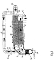
- the heat recovery process is set to status Variant 2 (two-thirds load - ie current plus Partial heat recovery mode) off by the tube bundle partition wall and the connecting space partition wall - closing the combustion gas direct guide opening in the flue pipe connecting space - interconnecting position of the two-position barrier flap, and with the barrier flap of the bypass tube open only the first heat exchanger tube and then only more of the entire flue pipe connection space and arranged there pipe evaporator from flowing out of the combustion furnace hot combustion gases are flowed through or, after which the same with open bypass flap only in and through the bypass pipe and by the gas -Abzugsraum and its exhaust discharge opening are guided or removed.
- status Variant 2 two-thirds load - ie current plus Partial heat recovery mode
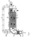
- a process management according to variant 3 (third-load, so only partial heat recovery mode) of advantage, which is characterized in that at - After swinging the two-position blocking flap - open combustion gas direct guide opening and as a result of entering thereby preventing the leadership of the combustion gases through the entire flue pipe connection space and thus on the same arranged in the same tube evaporator and at the same time closed bypass flap the effluent from the combustion furnace, hot combustion gases are guided or discharged only through both the first heat exchanger tube and the second heat exchanger tube and ultimately through the gas exhaust space and the exhaust gas discharge opening.
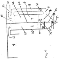
- the Fig. 1 schematically shows a connected to any combustion furnace 1 heat exchange device 6, here with vertical heat exchanger 60 separated by a partition 65 first and second tube bundles 61, 62, wherein in the operating state of the device 6, the first tube bundle 61 always first of the hot combustion gases 50th from the combustion furnace 1 is flowed through.
- the two tube bundles 61, 62 are to flow through each other in opposite directions and are above the flue pipe connecting space 7 with here conical lower part 9 with ash and / or Staubaustrags adopted 91 and arranged in the same, to an outside of the heat exchanger 6 arranged, not shown turbine with power generator connected evaporator coil 90 with each other.
- connection space 7 From the connection space 7 is an approximately C-shaped overall shape having, the second tube bundle 62 bypass bypass 8 bypassing, which opens in the output side of this second tube bundle 82 gas discharge space 85 and in which bypass tube 8 is relatively close to the connection space 7 for a possible barrier of the bypass tube 8 provided blocking flap 71 is located.
- the same dividing connecting space partition wall 75 is arranged, to which a either in a connection position A to Ruhrbündel partition wall 65 towards swiveling and in this case the gas direct guide opening 67 occlusive or in the access of the first tube bundle 61st leaving combustion gases to the evaporator 90 locking position B pivotable and thus the gas direct guide opening 67 opening two-position locking flap 70 is hinged.
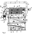
- the from the Fig. 2 resulting heat recovery system 6 comprises a directly applied to the ceiling 10 of a special kiln 1 or even a part thereof forming, horizontally disposed tube heat exchanger 6, which a through the tube bundle partition 65 in two pipe sections 61, 62 longitudinally divided tube bundle body 60 by the outflowing from the combustion furnace 1 hot combustion gases 50 first and second Rohrzug 61, 62, one - here left - directly to the tube bundle body 60 and subsequent the two pipe runs 61, 62 interconnecting the smoke pipe connection space 7 with the same dividing space partition 75, a arranged in the flue pipe connecting space 7, preferably connected to a turbine arranged outside of this smoke pipe connecting space 7 with power generator 95, tube evaporator 90 and a downward, with an ash and / or dust discharge unit 91 provided, cone 9th
- the system further includes the outgoing from the flue pipe connection space 7 and in the second pipe 62 of the heat exchanger 60 subsequent gas-Abzugsraum 85 with exhaust discharge opening 83 opening bypass pipe 8 with in their, starting from the flue connection chamber 7 - here ascending - pipe branch 81 built-in bypass pipe-trap 71st
- a heat exchanger either in - the local gas direct guide opening 67 gastight closing and so the leadership of the combustion gases 50 from the first pipe 61 through the flue pipe connection space 7 and via the same disposed in the same tube evaporator 90 in the second pipe 62th or equal to the bypass pipe 8 ensuring - partition wall connection position A to the tube bundle partition 65 of the heat exchanger 6 out or in the leadership of the combustion gases 50 from the first pipe 61 through the entire flue connection chamber 7 and on the same located in the same tube evaporator 90th preventing and thus their leadership by the open gas direct guide opening 67 directly into and through the bypass pipeline ensuring locking position B pivotable two-position locking flap 70 is articulated.
- the two-position locking flap 70 is in the in Fig. 2 shown full load, ie electricity plus heat recovery mode, variant 1, in which the tube bundle partition wall 65 and the connecting space partition wall 75 and interconnecting in this position the gas direct guide opening 67 closing position A brought.
- the hot combustion gases 50 flow through the first pipe 61, then flow through the entire flue connection chamber 7 and flow around there positioned tube evaporator 90, which has an outboard and not shown in the figure turbine with power generator 95, e.g. with superheated steam, supplied.
- the Fig. 2 further shows the special, essentially box-shaped incinerator 1 with two combustion chambers 4, 5 for as desired according to the invention, most effective combustion also optionally relatively small proportions of combustible substances containing material 10, the presentation of such a furnace explained in more detail, but not is the actual subject of the present invention.
- an obliquely ascending, in the direction tr material transporting staircase 2 is arranged, which the discontinued on him, combustible material 10, e.g. Chicken manure, slowly transported in the combustion chamber 4 in the direction of tr upwards.
- combustible material e.g. Chicken manure
- the liberated from the fuel 10 combustion gases 50 flow into the expanding primary combustion chamber 4 between the inclined upwardly rising transport grate 2 and the obliquely inclined as the transport grate 2 obliquely upward combustion chamber partition wall 45 in the + TR direction upwards and pass through the opening 54 left free from the aforementioned partition wall 45 in the obliquely downwardly expanding secondary combustion chamber 5 with a formed by the combustion chamber partition wall 45, sloping downward type ground with burn stones 450, where the gases in negative Continue direction -TR diagonally downwards.
- the hot combustion gases 50 leave - the chicane 11 on the underside immediately - finally the secondary combustion chamber 5 through the gas discharge opening 101 of the combustion device 1 and enter the inventive, as described above, horizontally arranged heat recovery device. 6
- the Fig. 3 shows - with otherwise constant reference numerals - the procedure when the temperature and the energy content of the combustion gases 50 are in a middle range, ie in the two-thirds, so current and partial heat recovery mode, variant 2.
- the Fig. 4 shows - with otherwise constant reference numerals - the way of coming from the combustion furnace 1 combustion gases 50 in the operating mode 3, ie in the third-party, so only partial heat recovery mode, variant 3.
- the gas direct guide opening 67 is opened in the flue connection tube 7, however, the blocking flap 81 is closed in the bypass tube 8 and the first flowing through the first tube 61 of the heat exchanger 60 combustion gases 50 arrive via the shortest route through the flue connection chamber 7 in and through the second pipe train 62nd and the adjoining gas exhaust space 85 and through the exhaust gas guide opening 83 to the outside.
Landscapes
- Engineering & Computer Science (AREA)
- Mechanical Engineering (AREA)
- General Engineering & Computer Science (AREA)
- Physics & Mathematics (AREA)
- Thermal Sciences (AREA)
- Chemical & Material Sciences (AREA)
- Combustion & Propulsion (AREA)
- Heat-Exchange Devices With Radiators And Conduit Assemblies (AREA)
Applications Claiming Priority (1)
| Application Number | Priority Date | Filing Date | Title |
|---|---|---|---|
| ATA51173/2016A AT519237B1 (de) | 2016-12-21 | 2016-12-21 | Anlage für die Rückgewinnung von Wärme |
Publications (2)
| Publication Number | Publication Date |
|---|---|
| EP3339733A1 true EP3339733A1 (fr) | 2018-06-27 |
| EP3339733B1 EP3339733B1 (fr) | 2019-11-13 |
Family
ID=60812006
Family Applications (1)
| Application Number | Title | Priority Date | Filing Date |
|---|---|---|---|
| EP17455001.2A Not-in-force EP3339733B1 (fr) | 2016-12-21 | 2017-12-21 | Installation de récupération de chaleur |
Country Status (3)
| Country | Link |
|---|---|
| EP (1) | EP3339733B1 (fr) |
| AT (1) | AT519237B1 (fr) |
| ES (1) | ES2767067T3 (fr) |
Cited By (2)
| Publication number | Priority date | Publication date | Assignee | Title |
|---|---|---|---|---|
| RU2709251C1 (ru) * | 2019-07-01 | 2019-12-17 | Вадим Михайлович Волков | Способ подогрева воздуха для обогрева промышленных и производственных объектов |
| RU2720428C1 (ru) * | 2019-07-16 | 2020-04-29 | Общество с ограниченной ответственностью Торговый дом "Кемеровский экспериментальный завод средств безопасности" | Теплоэнергетический комплекс для теплоснабжения горных выработок и помещений большого объема и способ |
Families Citing this family (2)
| Publication number | Priority date | Publication date | Assignee | Title |
|---|---|---|---|---|
| CN106733507B (zh) * | 2017-02-21 | 2022-11-04 | 常州市鼎龙环保设备有限公司 | 环保型涂机房净气系统 |
| CN118274338B (zh) * | 2024-05-09 | 2025-05-02 | 青岛能源设计研究院有限公司 | 一种生物质燃烧锅炉自动送料装置及助燃除渣系统 |
Citations (2)
| Publication number | Priority date | Publication date | Assignee | Title |
|---|---|---|---|---|
| US4031862A (en) * | 1976-03-10 | 1977-06-28 | Smith Frank J | Economizer |
| DE3331545A1 (de) * | 1983-08-13 | 1985-02-28 | Ferdinand Lentjes, Dampfkessel- und Maschinenbau, 4000 Düsseldorf | Verfahren und anlage zum vermindern der schadstoffemission in rauchgasen von feuerungsanlagen |
Family Cites Families (2)
| Publication number | Priority date | Publication date | Assignee | Title |
|---|---|---|---|---|
| DE3218984C2 (de) * | 1982-05-19 | 1994-04-28 | Schatz Oskar | Wärmetauscheranordnung für den Betrieb mit den Abgasen eines Kolbenmotors |
| JP5351840B2 (ja) * | 2010-06-25 | 2013-11-27 | 三菱重工業株式会社 | 排ガスの余熱回収装置 |
-
2016
- 2016-12-21 AT ATA51173/2016A patent/AT519237B1/de not_active IP Right Cessation
-
2017
- 2017-12-21 EP EP17455001.2A patent/EP3339733B1/fr not_active Not-in-force
- 2017-12-21 ES ES17455001T patent/ES2767067T3/es active Active
Patent Citations (2)
| Publication number | Priority date | Publication date | Assignee | Title |
|---|---|---|---|---|
| US4031862A (en) * | 1976-03-10 | 1977-06-28 | Smith Frank J | Economizer |
| DE3331545A1 (de) * | 1983-08-13 | 1985-02-28 | Ferdinand Lentjes, Dampfkessel- und Maschinenbau, 4000 Düsseldorf | Verfahren und anlage zum vermindern der schadstoffemission in rauchgasen von feuerungsanlagen |
Cited By (2)
| Publication number | Priority date | Publication date | Assignee | Title |
|---|---|---|---|---|
| RU2709251C1 (ru) * | 2019-07-01 | 2019-12-17 | Вадим Михайлович Волков | Способ подогрева воздуха для обогрева промышленных и производственных объектов |
| RU2720428C1 (ru) * | 2019-07-16 | 2020-04-29 | Общество с ограниченной ответственностью Торговый дом "Кемеровский экспериментальный завод средств безопасности" | Теплоэнергетический комплекс для теплоснабжения горных выработок и помещений большого объема и способ |
Also Published As
| Publication number | Publication date |
|---|---|
| AT519237A4 (de) | 2018-05-15 |
| AT519237B1 (de) | 2018-05-15 |
| EP3339733B1 (fr) | 2019-11-13 |
| ES2767067T3 (es) | 2020-06-16 |
Similar Documents
| Publication | Publication Date | Title |
|---|---|---|
| EP0636280B1 (fr) | Procede et dispositif permettant de convertir l'energie chimique d'un combustible en energie thermique et simultanement directement en energie electrique | |
| EP3339733B1 (fr) | Installation de récupération de chaleur | |
| DE3517987A1 (de) | Verfahren und vorrichtung zur steuerung der funktion eines wirbelschichtreaktors mit zirkulierender wirbelschicht | |
| DE2836531A1 (de) | Fliessbett-verbrennungsvorrichtung | |
| DE4014415C2 (de) | Vorrichtung zur katalytischen Oxidation der schädlichen Bestandteile in einem abgekühlten Trägergas eines verfahrenstechnischen Prozesses | |
| DE2520447A1 (de) | Thermisches kraftwerk | |
| DE202013001669U1 (de) | Anlage mit Biomassen-Mischverbrennung | |
| DE4344857A1 (de) | Verfahren und Vorrichtung zum Betreiben einer Gasturbine in einem einfachen und einem mit einer Dampfturbine kombinierten Zyklus | |
| DE2036731A1 (de) | Anlage zum Reinigen von Fluiden Mm Ptoctor & Schwartz. Inc , Philadel phia, Pa (VStA) | |
| DD291803A5 (de) | Anlage und verfahren zur regelung der temperatur von zwischenueberhitzungsdampf bei dampfkesseln mit zirkulierender wirbelschicht | |
| EP0098481B1 (fr) | Méthode pour générer de l'énergie électrique dans une centrale combinée à combustion en lit fluidisé | |
| WO2014056576A1 (fr) | Dispositif et procédé pour générer une pluralité de flux de vapeur ou d'eau chaude dans une série de fours à coke | |
| DE202017107929U1 (de) | Anlage zur Verbrennung organischen Materials | |
| DE420072C (de) | Kessel fuer ortsbewegliche Anlagen | |
| EP0035783B1 (fr) | Méthode et dispositif pour produire de l'électricité et de la chaleur à partir de combustible | |
| DE3507962A1 (de) | Feuerstaette fuer waermeerzeuger wie heizkessel, heizoefen o.dgl. | |
| EP0618404B1 (fr) | Procédé et installation pour la génération de vapeur dans une centrale de puissance et de chaleur | |
| DE19521161C1 (de) | Verfahren zur Umhüllung eines in einem Naturzugkühlturm aufsteigenden Rauchgasstromes mit einem Luftstrom sowie zugehöriger Naturzugkühlturm | |
| DE102014105477A1 (de) | Verfahren und Vorrichtung zur Trocknung von feuchtem, kohlenstoffhaltigem und partikelförmigem Brennstoff | |
| DE684018C (de) | Verfahren und Einrichtung zum Regeln der UEberhitzungstemperatur bei einem Wasserrohrkessel mit zwei mit eigener Feuerung ausgeruesteten Brennkammern und zwischen den Brennkammern liegendem UEberhitzer | |
| AT518525B1 (de) | Anlage und Verfahren zur Verbrennung organischen Materials | |
| DD256081A5 (de) | Fliessbettreaktor | |
| DE241413C (fr) | ||
| DE3501990A1 (de) | Anlage mit rostfeuerung fuer ersatzbrennstoffe wie muell | |
| DE1918394C3 (de) | Doppelwandiger Müllverbrennungsofen |
Legal Events
| Date | Code | Title | Description |
|---|---|---|---|
| PUAI | Public reference made under article 153(3) epc to a published international application that has entered the european phase |
Free format text: ORIGINAL CODE: 0009012 |
|
| STAA | Information on the status of an ep patent application or granted ep patent |
Free format text: STATUS: THE APPLICATION HAS BEEN PUBLISHED |
|
| AK | Designated contracting states |
Kind code of ref document: A1 Designated state(s): AL AT BE BG CH CY CZ DE DK EE ES FI FR GB GR HR HU IE IS IT LI LT LU LV MC MK MT NL NO PL PT RO RS SE SI SK SM TR |
|
| AX | Request for extension of the european patent |
Extension state: BA ME |
|
| STAA | Information on the status of an ep patent application or granted ep patent |
Free format text: STATUS: REQUEST FOR EXAMINATION WAS MADE |
|
| 17P | Request for examination filed |
Effective date: 20181220 |
|
| RBV | Designated contracting states (corrected) |
Designated state(s): AL AT BE BG CH CY CZ DE DK EE ES FI FR GB GR HR HU IE IS IT LI LT LU LV MC MK MT NL NO PL PT RO RS SE SI SK SM TR |
|
| STAA | Information on the status of an ep patent application or granted ep patent |
Free format text: STATUS: EXAMINATION IS IN PROGRESS |
|
| 17Q | First examination report despatched |
Effective date: 20190401 |
|
| GRAP | Despatch of communication of intention to grant a patent |
Free format text: ORIGINAL CODE: EPIDOSNIGR1 |
|
| STAA | Information on the status of an ep patent application or granted ep patent |
Free format text: STATUS: GRANT OF PATENT IS INTENDED |
|
| INTG | Intention to grant announced |
Effective date: 20190603 |
|
| GRAS | Grant fee paid |
Free format text: ORIGINAL CODE: EPIDOSNIGR3 |
|
| GRAA | (expected) grant |
Free format text: ORIGINAL CODE: 0009210 |
|
| STAA | Information on the status of an ep patent application or granted ep patent |
Free format text: STATUS: THE PATENT HAS BEEN GRANTED |
|
| AK | Designated contracting states |
Kind code of ref document: B1 Designated state(s): AL AT BE BG CH CY CZ DE DK EE ES FI FR GB GR HR HU IE IS IT LI LT LU LV MC MK MT NL NO PL PT RO RS SE SI SK SM TR |
|
| REG | Reference to a national code |
Ref country code: CH Ref legal event code: EP Ref country code: AT Ref legal event code: REF Ref document number: 1202041 Country of ref document: AT Kind code of ref document: T Effective date: 20191115 |
|
| REG | Reference to a national code |
Ref country code: DE Ref legal event code: R096 Ref document number: 502017002864 Country of ref document: DE |
|
| REG | Reference to a national code |
Ref country code: IE Ref legal event code: FG4D Free format text: LANGUAGE OF EP DOCUMENT: GERMAN |
|
| REG | Reference to a national code |
Ref country code: NL Ref legal event code: MP Effective date: 20191113 |
|
| REG | Reference to a national code |
Ref country code: LT Ref legal event code: MG4D |
|
| PG25 | Lapsed in a contracting state [announced via postgrant information from national office to epo] |
Ref country code: PT Free format text: LAPSE BECAUSE OF FAILURE TO SUBMIT A TRANSLATION OF THE DESCRIPTION OR TO PAY THE FEE WITHIN THE PRESCRIBED TIME-LIMIT Effective date: 20200313 Ref country code: SE Free format text: LAPSE BECAUSE OF FAILURE TO SUBMIT A TRANSLATION OF THE DESCRIPTION OR TO PAY THE FEE WITHIN THE PRESCRIBED TIME-LIMIT Effective date: 20191113 Ref country code: LV Free format text: LAPSE BECAUSE OF FAILURE TO SUBMIT A TRANSLATION OF THE DESCRIPTION OR TO PAY THE FEE WITHIN THE PRESCRIBED TIME-LIMIT Effective date: 20191113 Ref country code: NL Free format text: LAPSE BECAUSE OF FAILURE TO SUBMIT A TRANSLATION OF THE DESCRIPTION OR TO PAY THE FEE WITHIN THE PRESCRIBED TIME-LIMIT Effective date: 20191113 Ref country code: LT Free format text: LAPSE BECAUSE OF FAILURE TO SUBMIT A TRANSLATION OF THE DESCRIPTION OR TO PAY THE FEE WITHIN THE PRESCRIBED TIME-LIMIT Effective date: 20191113 Ref country code: GR Free format text: LAPSE BECAUSE OF FAILURE TO SUBMIT A TRANSLATION OF THE DESCRIPTION OR TO PAY THE FEE WITHIN THE PRESCRIBED TIME-LIMIT Effective date: 20200214 Ref country code: NO Free format text: LAPSE BECAUSE OF FAILURE TO SUBMIT A TRANSLATION OF THE DESCRIPTION OR TO PAY THE FEE WITHIN THE PRESCRIBED TIME-LIMIT Effective date: 20200213 Ref country code: PL Free format text: LAPSE BECAUSE OF FAILURE TO SUBMIT A TRANSLATION OF THE DESCRIPTION OR TO PAY THE FEE WITHIN THE PRESCRIBED TIME-LIMIT Effective date: 20191113 Ref country code: FI Free format text: LAPSE BECAUSE OF FAILURE TO SUBMIT A TRANSLATION OF THE DESCRIPTION OR TO PAY THE FEE WITHIN THE PRESCRIBED TIME-LIMIT Effective date: 20191113 Ref country code: BG Free format text: LAPSE BECAUSE OF FAILURE TO SUBMIT A TRANSLATION OF THE DESCRIPTION OR TO PAY THE FEE WITHIN THE PRESCRIBED TIME-LIMIT Effective date: 20200213 |
|
| PG25 | Lapsed in a contracting state [announced via postgrant information from national office to epo] |
Ref country code: RS Free format text: LAPSE BECAUSE OF FAILURE TO SUBMIT A TRANSLATION OF THE DESCRIPTION OR TO PAY THE FEE WITHIN THE PRESCRIBED TIME-LIMIT Effective date: 20191113 Ref country code: HR Free format text: LAPSE BECAUSE OF FAILURE TO SUBMIT A TRANSLATION OF THE DESCRIPTION OR TO PAY THE FEE WITHIN THE PRESCRIBED TIME-LIMIT Effective date: 20191113 Ref country code: IS Free format text: LAPSE BECAUSE OF FAILURE TO SUBMIT A TRANSLATION OF THE DESCRIPTION OR TO PAY THE FEE WITHIN THE PRESCRIBED TIME-LIMIT Effective date: 20200313 |
|
| REG | Reference to a national code |
Ref country code: ES Ref legal event code: FG2A Ref document number: 2767067 Country of ref document: ES Kind code of ref document: T3 Effective date: 20200616 |
|
| PG25 | Lapsed in a contracting state [announced via postgrant information from national office to epo] |
Ref country code: AL Free format text: LAPSE BECAUSE OF FAILURE TO SUBMIT A TRANSLATION OF THE DESCRIPTION OR TO PAY THE FEE WITHIN THE PRESCRIBED TIME-LIMIT Effective date: 20191113 |
|
| PG25 | Lapsed in a contracting state [announced via postgrant information from national office to epo] |
Ref country code: RO Free format text: LAPSE BECAUSE OF FAILURE TO SUBMIT A TRANSLATION OF THE DESCRIPTION OR TO PAY THE FEE WITHIN THE PRESCRIBED TIME-LIMIT Effective date: 20191113 Ref country code: EE Free format text: LAPSE BECAUSE OF FAILURE TO SUBMIT A TRANSLATION OF THE DESCRIPTION OR TO PAY THE FEE WITHIN THE PRESCRIBED TIME-LIMIT Effective date: 20191113 Ref country code: DK Free format text: LAPSE BECAUSE OF FAILURE TO SUBMIT A TRANSLATION OF THE DESCRIPTION OR TO PAY THE FEE WITHIN THE PRESCRIBED TIME-LIMIT Effective date: 20191113 Ref country code: CZ Free format text: LAPSE BECAUSE OF FAILURE TO SUBMIT A TRANSLATION OF THE DESCRIPTION OR TO PAY THE FEE WITHIN THE PRESCRIBED TIME-LIMIT Effective date: 20191113 |
|
| REG | Reference to a national code |
Ref country code: DE Ref legal event code: R097 Ref document number: 502017002864 Country of ref document: DE |
|
| REG | Reference to a national code |
Ref country code: BE Ref legal event code: MM Effective date: 20191231 |
|
| PG25 | Lapsed in a contracting state [announced via postgrant information from national office to epo] |
Ref country code: SM Free format text: LAPSE BECAUSE OF FAILURE TO SUBMIT A TRANSLATION OF THE DESCRIPTION OR TO PAY THE FEE WITHIN THE PRESCRIBED TIME-LIMIT Effective date: 20191113 Ref country code: SK Free format text: LAPSE BECAUSE OF FAILURE TO SUBMIT A TRANSLATION OF THE DESCRIPTION OR TO PAY THE FEE WITHIN THE PRESCRIBED TIME-LIMIT Effective date: 20191113 Ref country code: MC Free format text: LAPSE BECAUSE OF FAILURE TO SUBMIT A TRANSLATION OF THE DESCRIPTION OR TO PAY THE FEE WITHIN THE PRESCRIBED TIME-LIMIT Effective date: 20191113 |
|
| PLBE | No opposition filed within time limit |
Free format text: ORIGINAL CODE: 0009261 |
|
| STAA | Information on the status of an ep patent application or granted ep patent |
Free format text: STATUS: NO OPPOSITION FILED WITHIN TIME LIMIT |
|
| 26N | No opposition filed |
Effective date: 20200814 |
|
| PG25 | Lapsed in a contracting state [announced via postgrant information from national office to epo] |
Ref country code: IE Free format text: LAPSE BECAUSE OF NON-PAYMENT OF DUE FEES Effective date: 20191221 Ref country code: LU Free format text: LAPSE BECAUSE OF NON-PAYMENT OF DUE FEES Effective date: 20191221 |
|
| PG25 | Lapsed in a contracting state [announced via postgrant information from national office to epo] |
Ref country code: SI Free format text: LAPSE BECAUSE OF FAILURE TO SUBMIT A TRANSLATION OF THE DESCRIPTION OR TO PAY THE FEE WITHIN THE PRESCRIBED TIME-LIMIT Effective date: 20191113 Ref country code: BE Free format text: LAPSE BECAUSE OF NON-PAYMENT OF DUE FEES Effective date: 20191231 |
|
| PGFP | Annual fee paid to national office [announced via postgrant information from national office to epo] |
Ref country code: DE Payment date: 20201211 Year of fee payment: 4 Ref country code: IT Payment date: 20201231 Year of fee payment: 4 Ref country code: FR Payment date: 20201223 Year of fee payment: 4 |
|
| PG25 | Lapsed in a contracting state [announced via postgrant information from national office to epo] |
Ref country code: CY Free format text: LAPSE BECAUSE OF FAILURE TO SUBMIT A TRANSLATION OF THE DESCRIPTION OR TO PAY THE FEE WITHIN THE PRESCRIBED TIME-LIMIT Effective date: 20191113 |
|
| PGFP | Annual fee paid to national office [announced via postgrant information from national office to epo] |
Ref country code: ES Payment date: 20210223 Year of fee payment: 4 |
|
| PG25 | Lapsed in a contracting state [announced via postgrant information from national office to epo] |
Ref country code: HU Free format text: LAPSE BECAUSE OF FAILURE TO SUBMIT A TRANSLATION OF THE DESCRIPTION OR TO PAY THE FEE WITHIN THE PRESCRIBED TIME-LIMIT; INVALID AB INITIO Effective date: 20171221 Ref country code: MT Free format text: LAPSE BECAUSE OF FAILURE TO SUBMIT A TRANSLATION OF THE DESCRIPTION OR TO PAY THE FEE WITHIN THE PRESCRIBED TIME-LIMIT Effective date: 20191113 |
|
| REG | Reference to a national code |
Ref country code: CH Ref legal event code: PL |
|
| PG25 | Lapsed in a contracting state [announced via postgrant information from national office to epo] |
Ref country code: LI Free format text: LAPSE BECAUSE OF NON-PAYMENT OF DUE FEES Effective date: 20201231 Ref country code: CH Free format text: LAPSE BECAUSE OF NON-PAYMENT OF DUE FEES Effective date: 20201231 |
|
| PG25 | Lapsed in a contracting state [announced via postgrant information from national office to epo] |
Ref country code: TR Free format text: LAPSE BECAUSE OF FAILURE TO SUBMIT A TRANSLATION OF THE DESCRIPTION OR TO PAY THE FEE WITHIN THE PRESCRIBED TIME-LIMIT Effective date: 20191113 |
|
| PG25 | Lapsed in a contracting state [announced via postgrant information from national office to epo] |
Ref country code: MK Free format text: LAPSE BECAUSE OF FAILURE TO SUBMIT A TRANSLATION OF THE DESCRIPTION OR TO PAY THE FEE WITHIN THE PRESCRIBED TIME-LIMIT Effective date: 20191113 |
|
| REG | Reference to a national code |
Ref country code: DE Ref legal event code: R119 Ref document number: 502017002864 Country of ref document: DE |
|
| GBPC | Gb: european patent ceased through non-payment of renewal fee |
Effective date: 20211221 |
|
| PG25 | Lapsed in a contracting state [announced via postgrant information from national office to epo] |
Ref country code: GB Free format text: LAPSE BECAUSE OF NON-PAYMENT OF DUE FEES Effective date: 20211221 Ref country code: DE Free format text: LAPSE BECAUSE OF NON-PAYMENT OF DUE FEES Effective date: 20220701 |
|
| PG25 | Lapsed in a contracting state [announced via postgrant information from national office to epo] |
Ref country code: FR Free format text: LAPSE BECAUSE OF NON-PAYMENT OF DUE FEES Effective date: 20211231 |
|
| PG25 | Lapsed in a contracting state [announced via postgrant information from national office to epo] |
Ref country code: IT Free format text: LAPSE BECAUSE OF NON-PAYMENT OF DUE FEES Effective date: 20211221 |
|
| REG | Reference to a national code |
Ref country code: ES Ref legal event code: FD2A Effective date: 20230207 |
|
| PG25 | Lapsed in a contracting state [announced via postgrant information from national office to epo] |
Ref country code: ES Free format text: LAPSE BECAUSE OF NON-PAYMENT OF DUE FEES Effective date: 20211222 |
|
| REG | Reference to a national code |
Ref country code: AT Ref legal event code: MM01 Ref document number: 1202041 Country of ref document: AT Kind code of ref document: T Effective date: 20221221 |
|
| PG25 | Lapsed in a contracting state [announced via postgrant information from national office to epo] |
Ref country code: AT Free format text: LAPSE BECAUSE OF NON-PAYMENT OF DUE FEES Effective date: 20221221 |
|
| PG25 | Lapsed in a contracting state [announced via postgrant information from national office to epo] |
Ref country code: AT Free format text: LAPSE BECAUSE OF NON-PAYMENT OF DUE FEES Effective date: 20221221 |
|
| PGFP | Annual fee paid to national office [announced via postgrant information from national office to epo] |
Ref country code: AT Payment date: 20260410 Year of fee payment: 5 |