EP3339738A1 - Turbine comprenant une chambre de combustion de recirculation de gaz combustible - Google Patents
Turbine comprenant une chambre de combustion de recirculation de gaz combustible Download PDFInfo
- Publication number
- EP3339738A1 EP3339738A1 EP17202951.4A EP17202951A EP3339738A1 EP 3339738 A1 EP3339738 A1 EP 3339738A1 EP 17202951 A EP17202951 A EP 17202951A EP 3339738 A1 EP3339738 A1 EP 3339738A1
- Authority
- EP
- European Patent Office
- Prior art keywords
- nozzle
- combustor
- nozzle casing
- casing
- flow path
- Prior art date
- Legal status (The legal status is an assumption and is not a legal conclusion. Google has not performed a legal analysis and makes no representation as to the accuracy of the status listed.)
- Granted
Links
Images

Classifications
-
- F—MECHANICAL ENGINEERING; LIGHTING; HEATING; WEAPONS; BLASTING
- F02—COMBUSTION ENGINES; HOT-GAS OR COMBUSTION-PRODUCT ENGINE PLANTS
- F02C—GAS-TURBINE PLANTS; AIR INTAKES FOR JET-PROPULSION PLANTS; CONTROLLING FUEL SUPPLY IN AIR-BREATHING JET-PROPULSION PLANTS
- F02C3/00—Gas-turbine plants characterised by the use of combustion products as the working fluid
- F02C3/34—Gas-turbine plants characterised by the use of combustion products as the working fluid with recycling of part of the working fluid, i.e. semi-closed cycles with combustion products in the closed part of the cycle
-
- F—MECHANICAL ENGINEERING; LIGHTING; HEATING; WEAPONS; BLASTING
- F23—COMBUSTION APPARATUS; COMBUSTION PROCESSES
- F23R—GENERATING COMBUSTION PRODUCTS OF HIGH PRESSURE OR HIGH VELOCITY, e.g. GAS-TURBINE COMBUSTION CHAMBERS
- F23R3/00—Continuous combustion chambers using liquid or gaseous fuel
- F23R3/28—Continuous combustion chambers using liquid or gaseous fuel characterised by the fuel supply
- F23R3/286—Continuous combustion chambers using liquid or gaseous fuel characterised by the fuel supply having fuel-air premixing devices
-
- F—MECHANICAL ENGINEERING; LIGHTING; HEATING; WEAPONS; BLASTING
- F02—COMBUSTION ENGINES; HOT-GAS OR COMBUSTION-PRODUCT ENGINE PLANTS
- F02C—GAS-TURBINE PLANTS; AIR INTAKES FOR JET-PROPULSION PLANTS; CONTROLLING FUEL SUPPLY IN AIR-BREATHING JET-PROPULSION PLANTS
- F02C7/00—Features, components parts, details or accessories, not provided for in, or of interest apart form groups F02C1/00 - F02C6/00; Air intakes for jet-propulsion plants
- F02C7/22—Fuel supply systems
-
- F—MECHANICAL ENGINEERING; LIGHTING; HEATING; WEAPONS; BLASTING
- F02—COMBUSTION ENGINES; HOT-GAS OR COMBUSTION-PRODUCT ENGINE PLANTS
- F02C—GAS-TURBINE PLANTS; AIR INTAKES FOR JET-PROPULSION PLANTS; CONTROLLING FUEL SUPPLY IN AIR-BREATHING JET-PROPULSION PLANTS
- F02C9/00—Controlling gas-turbine plants; Controlling fuel supply in air- breathing jet-propulsion plants
- F02C9/26—Control of fuel supply
- F02C9/40—Control of fuel supply specially adapted to the use of a special fuel or a plurality of fuels
-
- F—MECHANICAL ENGINEERING; LIGHTING; HEATING; WEAPONS; BLASTING
- F23—COMBUSTION APPARATUS; COMBUSTION PROCESSES
- F23C—METHODS OR APPARATUS FOR COMBUSTION USING FLUID FUEL OR SOLID FUEL SUSPENDED IN A CARRIER GAS OR AIR
- F23C9/00—Combustion apparatus characterised by arrangements for returning combustion products or flue gases to the combustion chamber
-
- F—MECHANICAL ENGINEERING; LIGHTING; HEATING; WEAPONS; BLASTING
- F23—COMBUSTION APPARATUS; COMBUSTION PROCESSES
- F23R—GENERATING COMBUSTION PRODUCTS OF HIGH PRESSURE OR HIGH VELOCITY, e.g. GAS-TURBINE COMBUSTION CHAMBERS
- F23R3/00—Continuous combustion chambers using liquid or gaseous fuel
- F23R3/42—Continuous combustion chambers using liquid or gaseous fuel characterised by the arrangement or form of the flame tubes or combustion chambers
- F23R3/46—Combustion chambers comprising an annular arrangement of several essentially tubular flame tubes within a common annular casing or within individual casings
-
- F—MECHANICAL ENGINEERING; LIGHTING; HEATING; WEAPONS; BLASTING
- F05—INDEXING SCHEMES RELATING TO ENGINES OR PUMPS IN VARIOUS SUBCLASSES OF CLASSES F01-F04
- F05D—INDEXING SCHEME FOR ASPECTS RELATING TO NON-POSITIVE-DISPLACEMENT MACHINES OR ENGINES, GAS-TURBINES OR JET-PROPULSION PLANTS
- F05D2220/00—Application
- F05D2220/30—Application in turbines
- F05D2220/32—Application in turbines in gas turbines
-
- F—MECHANICAL ENGINEERING; LIGHTING; HEATING; WEAPONS; BLASTING
- F05—INDEXING SCHEMES RELATING TO ENGINES OR PUMPS IN VARIOUS SUBCLASSES OF CLASSES F01-F04
- F05D—INDEXING SCHEME FOR ASPECTS RELATING TO NON-POSITIVE-DISPLACEMENT MACHINES OR ENGINES, GAS-TURBINES OR JET-PROPULSION PLANTS
- F05D2240/00—Components
- F05D2240/35—Combustors or associated equipment
-
- F—MECHANICAL ENGINEERING; LIGHTING; HEATING; WEAPONS; BLASTING
- F05—INDEXING SCHEMES RELATING TO ENGINES OR PUMPS IN VARIOUS SUBCLASSES OF CLASSES F01-F04
- F05D—INDEXING SCHEME FOR ASPECTS RELATING TO NON-POSITIVE-DISPLACEMENT MACHINES OR ENGINES, GAS-TURBINES OR JET-PROPULSION PLANTS
- F05D2260/00—Function
- F05D2260/60—Fluid transfer
- F05D2260/606—Bypassing the fluid
-
- F—MECHANICAL ENGINEERING; LIGHTING; HEATING; WEAPONS; BLASTING
- F23—COMBUSTION APPARATUS; COMBUSTION PROCESSES
- F23C—METHODS OR APPARATUS FOR COMBUSTION USING FLUID FUEL OR SOLID FUEL SUSPENDED IN A CARRIER GAS OR AIR
- F23C2202/00—Fluegas recirculation
- F23C2202/10—Premixing fluegas with fuel and combustion air
-
- F—MECHANICAL ENGINEERING; LIGHTING; HEATING; WEAPONS; BLASTING
- F23—COMBUSTION APPARATUS; COMBUSTION PROCESSES
- F23C—METHODS OR APPARATUS FOR COMBUSTION USING FLUID FUEL OR SOLID FUEL SUSPENDED IN A CARRIER GAS OR AIR
- F23C2202/00—Fluegas recirculation
- F23C2202/50—Control of recirculation rate
Definitions
- the present disclosure relates generally to a gas turbine. More particularly, the present disclosure relates to a turbine including a flue gas recirculation combustor, wherein NOx (nitrogen oxides) is reduced by recirculating the flue gas to lower the oxygen concentration of premixed fuel (mixture of mist fuel and air) in a combustor chamber that combusts the premixed fuel of fuel and air (mixture of mist fuel and air) injected from a nozzle, NOx (nitrogen oxides) can be reduced by recirculating the flue gas to lower the oxygen concentration in the premixed fuel.
- NOx nitrogen oxides
- a gas turbine is a rotary type heat engine that drives a turbine with high temperature and high pressure combustion gas.
- a mixture of fuel and air injected from the combustion nozzle must be combusted in the combustion chamber provided in the combustor. While combustion continues, the gas turbine continues to operate until fuel and air supply (especially, the fuel supply) is stopped.
- the igniter may be of the type that emits electrical energy or uses electrical energy to heat an end portion thereof, or it may be of an ignition torch type that bums the fuel.
- the fuel/air mixture combusted in the combustor chamber emits a large amount of nitrogen oxides (NOx).
- nitrogen oxides as pollutants, must be reduced to avoid environmental pollution.
- a method of suppressing the generation of nitrogen oxides by reducing the oxygen concentration contained in the combusting fuel/air mixture can be used.
- An object of the present disclosure is to provide a gas turbine, which is operated by igniting a mixture of fuel and air injected into a combustion chamber thereof, having a bypass path or an ejector nozzle at a side of the combustor chamber to lower the oxygen concentration of fuel.
- a flue gas recirculation combustor including a combustor chamber configured such that fuel and combustion gas are injected therein to cause combustion, a nozzle-side end with a nozzle can and a plurality of nozzles connected thereto, and a combustor outlet, wherein the nozzle can is connected to the nozzle-side end of the combustor chamber and the plurality of nozzles are inserted into the nozzle can, and configured such that an injection direction thereof is directed to a side of the combustor chamber, wherein a sleeve provided in a premixing space defined between the nozzle can and the nozzle-side end of the combustor chamber is provided with at least one of a bypass path and an ejector nozzle.
- the plurality of nozzles may be arranged to form at least one concentric circle based on a center of the nozzle can having a circular longitudinal section, with the nozzles arranged to be spaced from each other at predetermined intervals in one circular nozzle arrangement.
- the plurality of nozzles may be configured such that combustion air and fuel are premixed therein and injected therefrom.
- bypass path or the ejector nozzle may be provided through the sleeve arranged between the nozzle can and the nozzle-side end of the combustor chamber connected to the nozzle can, with at least one or more thereof provided on an inner surface of the sleeve along a circumferential direction.
- both the bypass path and the ejector nozzle may be provided through the sleeve, with the ejector nozzle provided between one bypass path and neighboring bypass path, the bypass path being configured such that at least one or more thereof are provided at a predetermined interval on the inner surface of the sleeve along the circumferential direction.
- the ejector nozzle may include a nozzle casing provided in the sleeve through the same, an injection control needle assembly provided in the nozzle casing, a combustor flow path connecting at least one point of the nozzle casing and a side of the combustor chamber, and a premix flow path connecting a side of the nozzle casing and the premixing space.
- the nozzle casing may be in a cylindrical shape with an end thereof closed, and the nozzle casing may include a narrowed part provided at an open end of the nozzle casing to inject gases in the combustor chamber to the premixing space, and a partition dividing the cylindrical nozzle casing by longitudinally bisecting the same.
- the injection control needle assembly may include a needle longitudinally provided at a center of the cylindrical nozzle casing with an end thereof closed, a movable member provided at an end of the needle to allow the needle to move horizontally along the center of the nozzle casing, a first elastic member provided between the partition of the nozzle casing and the movable member, and a second elastic member provided between the movable member and the closed end of the nozzle casing.
- the injection control needle assembly may further include an elasticity adjusting member screwed to the closed end of the nozzle casing to be connected to the second elastic member.
- the injection control needle assembly may further include at least one ring stopper limiting horizontal movement of the movable member in the nozzle casing.
- the combustor flow path may be configured such that an inlet end thereof is provided at the nozzle-side end of the combustor chamber and an outlet end thereof is provided at a side of the nozzle casing, and the outlet end includes a combustor pressure path communicating with a space between the partition and the movable member, and a recirculation flow path communicating with an injection path in the nozzle casing.
- the premix flow path may be configured such that an inlet end thereof is provided at a nozzle-side end of the sleeve and an outlet end thereof is provided at a side of the nozzle casing, with the outlet end communicating with a space between the movable member and the closed end of the nozzle casing.
- a turbine including a flue gas recirculation combustor of the present disclosure configured as described above, it is possible to reduce the amount of nitrogen oxides (NOx) contained in the exhaust gas.
- NOx nitrogen oxides
- premixing space provided between a plurality of nozzles and the combustor chamber, and the bypass path or the ejector nozzle provided in the sleeve are configured such that their shapes and installation positions have optimum efficiency and are self-driven.
- ⁇ part means a unit for processing at least one function or operation and may be implemented by a combination of hardware and/or software.
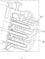
- FIG. 1 is a perspective view showing a gas turbine including a combustor chamber 100, a nozzle can 200, and nozzles 300 according to an exemplary embodiment of the present disclosure.
- the combustion process of the gas turbine is performed in such a manner that the fuel sprayed in the form of mist through the nozzles 300 and the combustion air required for combustion are supplied to the combustor chamber 100, and the ignition proceeds in the combustor chamber 100.
- the fuel and air may be premixed in an annular space between the nozzles 300 and the nozzle can 200 before being supplied to the combustor chamber 100.
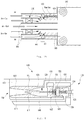
- FIG. 2 is a schematic view showing a gas turbine combustor including a combustor chamber 100 and nozzles 300 according to an embodiment of the conventional art.
- the conventional art is problematic in that there is no internal device capable of controlling the oxygen concentration of the mixture mixed in the premixing space, so the amount of nitrogen oxides in the discharged exhaust gas is considerable. Further, it can also be seen that there is no additional configuration to supply the combustion air in the combustion chamber to the premixing space or to mix the combustion air with premixed air.
- An exemplary embodiment of the present disclosure includes at least one of a bypass path and an ejector nozzle, whereby it is possible to efficiently lower the oxygen concentration in the mixer produced by mixing the fuel sprayed in the form of mist through the nozzles 300 with the combustion air by blowing the combusted air present in the combustor chamber 100 into a premixing space as described in more detail below.
- FIG. 3 is a schematic view showing a gas turbine including a combustor chamber 100 and nozzles 300 according to an exemplary embodiment of the present disclosure. As shown in FIG. 3 , bypass path 500 is provided to lower the oxygen concentration of the mixer.
- a combustor of a gas turbine includes a flue gas recirculation combustor comprising a combustor chamber 100 configured such that fuel and combustion gas are injected therein to cause combustion, a nozzle-side end with a nozzle can 200 and a plurality of nozzles 300 connected thereto, and a combustor outlet.
- the nozzle can 200 is connected to the nozzle-side end of the combustor chamber 100 and the plurality of nozzles 300 are inserted into the nozzle can 200 and configured such that an injection direction thereof is directed to a side of the combustor chamber 100, wherein a sleeve 400 provided in a premixing space 700 defined between the nozzle can 200 and the nozzle-side end of the combustor chamber 100 is provided with at least one of a bypass path 500 and an ejector nozzle 600.
- the plurality of nozzles 300 may be arranged to form at least one concentric circle based on a center of the nozzle can 200 having a circular longitudinal section, with the nozzles 300 arranged to be spaced from each other at predetermined intervals in one circular nozzle arrangement. It is preferable that the combustion air and fuel are premixed and injected. Through this nozzle arrangement, it is possible to smoothly mix fuel, air, and fuel/air mixture in the premixing space 700.
- bypass path 500 or the ejector nozzle 600 may be provided through the sleeve 400 arranged between the nozzle can 200 and the nozzle-side end of the combustor chamber 100 connected to the nozzle can 200, with at least one or more thereof provided on an inner surface of the sleeve 400 along a circumferential direction. Further, both the bypass path 500 and the ejector nozzle 600 may be provided through the sleeve 400, with the ejector nozzle 600 provided between one bypass path 500 and neighboring bypass path 500, the bypass path 500 configured such that at least one or more thereof are provided at a predetermined interval on the inner surface of the sleeve 400 along the circumferential direction.
- bypass path 500 on the inner surface of the sleeve 400 along the circumferential direction, or may be possible to provide only the ejector nozzle 600 in the inner surface of the sleeve 400 along the circumferential direction.
- bypass path 500 and the ejector nozzle 600 may be also possible to alternately install the bypass path 500 and the ejector nozzle 600 on the inner surface of the sleeve 400 along the circumferential direction in order to reduce nitrogen oxides.
- bypass path 500 it is possible to obtain a mixing effect due to natural flow resulting from the pressure difference between the combustor chamber 100 and the premixing space 700.
- the ejector nozzle 600 it is possible to control the injection amount using the pressure difference. Therefore, a gas turbine capable of reducing nitrogen oxides at low cost and high efficiency may be achieved by appropriately disposing the ejector nozzle 600.
- bypass path 500 is configured such that a first end thereof is formed in the combustor chamber 100 in which the combustion air is formed at a high pressure, and a second end thereof is formed in the premixing space 700, it is possible to naturally deliver the high-pressure combustion air (i.e., air with a relatively large amount of nitrogen oxides and carbon dioxide) to the premixing space 700. Accordingly, by having such a configuration, it is possible to naturally deliver the high-pressure combustion air to the premixing space 700 without providing a separate driving force.
- the high-pressure combustion air i.e., air with a relatively large amount of nitrogen oxides and carbon dioxide
- FIG. 4 is a longitudinal sectional view showing the ejector nozzle 600 according to an exemplary embodiment of the present disclosure. Referring to FIG. 4 , an exemplary configuration of an ejector nozzle 600, which is a component of the present disclosure, self-driven, and capable of injection control, is shown.
- ejector nozzle 600 includes a nozzle casing 610 provided in the sleeve 400 shown in FIG. 3 , an injection control needle assembly 620 provided in the nozzle casing 610, a combustor flow path 630 connecting at least one point of the nozzle casing 610 and a side of the combustor chamber 100, and a premix flow path 640 connecting a side of the nozzle casing 610 and the premixing space 700.
- the nozzle casing 610 may be in a cylindrical shape with an end thereof closed, and the nozzle casing may include a narrowed part 611 provided at an open end of the nozzle casing 610 to inject gases in the combustor chamber 100 to the premixing space 700, and a partition 612 dividing the cylindrical nozzle casing 610 by longitudinally bisecting the same.
- the injection control needle assembly 620 may include a needle 621 longitudinally provided at a center of the cylindrical nozzle casing 610 with an end thereof closed, a movable member 622 provided at an end of the needle 621 to allow the needle 621 to move horizontally along the center of the nozzle casing 610, a first elastic member 623 provided between a partition 612 of the nozzle casing 610 and the movable member 622, a second elastic member 624 provided between the movable member 622 and the closed end of the nozzle casing 610, and an elasticity adjusting member 625 screwed to the closed end of the nozzle casing 610 to be connected to the second elastic member 624.
- the injection control needle assembly 620 may further include at least one ring stopper 626 limiting horizontal movement of the movable member 622 in the nozzle casing 610.
- the combustor flow path 630 is configured such that an inlet end thereof is provided at the nozzle-side end of the combustor chamber 100 and an outlet end thereof is provided at a side of the nozzle casing 610.
- the outlet end includes a combustor pressure path 631 communicating with a space between the partition 612 and the movable member 622, and a recirculation flow path 632 communicating with an injection path 613 in the nozzle casing 610.
- premix flow path 640 is configured such that an inlet end thereof is provided at a nozzle-side end of the sleeve 400 and an outlet end thereof is provided at a side of the nozzle casing 610, with the outlet end communicating with a space between the movable member 622 and the closed end of the nozzle casing 610.
- High pressure combustion air in the combustor chamber 100 naturally enters the combustor flow path 630, and the combustion air naturally entering the combustor flow path 630 splits into the combustor pressure path 631 and the recirculation flow path 632 and is introduced into the nozzle casing 610.
- the combustion air introduced into the nozzle casing 610 through the combustor pressure path 631 provides a force to push the movable member 622 in a direction toward the combustor chamber 100, and when the combustion air is supplied at a predetermined pressure or more, backward movement is restricted by the ringshaped ring stopper 626 provided at least one inside the nozzle casing 610.
- the needle 621 connected to the movable member 622 is also moved backward, and the gap between the narrowed part 611 and the needle 621 is increased, thereby increasing the amount of combustion air injected through the injection path 613.
- most of the combustion air delivered from the combustor chamber 100 through the recirculation flow path 632 is transferred to the premixing space 700.
- forward movement may be restricted by another ring stopper, not shown, provided at least one inside the nozzle casing 610.
- the elasticity adjusting member 625 may also be desirable to provide an elasticity adjusting member 625 that is screwed to the closed end of the nozzle casing 610.
- the elasticity adjusting member 625 is connected to the movable member 622 via the second elastic member 624, wherein by rotating the elasticity adjusting member 625 to adjust the preload of the second elastic member 624, it is possible to adjust the operational sensitivity of the movable member 622 in response to the pressure of the combustion air introduced into the nozzle casing 610 and the pressure of the premixed air introduced into the combustor chamber 100.
- a flue gas recirculation combustor comprises a combustor chamber (100) configured to receive fuel and combustion gas to cause combustion, the combustor chamber (100) including a nozzle-side end and a combustor outlet; a nozzle can (200) connected to the nozzle-side end of the combustor chamber (100); a plurality of nozzles (300) disposed in the nozzle can (200) and arranged such that an injection direction thereof is directed to a side of the combustor chamber (100); and a sleeve (400) disposed in a premixing space defined between the nozzle can (200) and the nozzle-side end of the combustor chamber (100), the sleeve (400) including a recirculation pathway to recirculate combustion air from the combustor chamber (100) to the premixing space (700).
- the recirculation pathway may include at least one of a bypass path (500) and an ejector nozzle (600).
- the plurality of nozzles (300) may bw configured to premix and inject combustion air and fuel.
- the recirculation pathway may be provided on an inner surface of the sleeve (400) along a circumferential direction.
- the recirculation pathway may include a bypass path (500) and an ejector nozzle (600), wherein the ejector nozzle (600) is arranged between one bypass path (500) and a neighboring bypass path (500), and the bypass paths (500) are arranged at a predetermined interval on the inner surface of the sleeve (400) along a circumferential direction.
- the ejector nozzle (600) may include a nozzle casing (610), an injection control needle assembly (620) disposed in the nozzle casing (610), a combustor flow path (630) connecting at least one point of the nozzle casing (610) and the nozzle-side end of the combustor chamber (100), and a premix flow path (640) connecting a side of the nozzle casing (610) and the premixing space (700).
- the nozzle casing (610) may have a closed end.
- the nozzle casing (610) may include a narrowed portion (611) provided at an open end of the nozzle casing (610) to inject gases from the combustor chamber (100) to the premixing space (700), and a partition (612) longitudinally dividing the nozzle casing (610).
- the injection control needle assembly (620) may include a needle (621) arranged longitudinally at a center of the nozzle casing (610), a movable member (622) arranged at an end of the needle (621) to move the needle (621) horizontally along the center of the nozzle casing (610), a first elastic member (623) arranged between the partition (612) of the nozzle casing (610) and the movable member (622), and a second elastic member (624) provided between the movable member (622) and the closed end of the nozzle casing (610).
- the injection control needle assembly (620) may include an elasticity adjusting member (625) arranged at the closed end of the nozzle casing (610) to be connected to the second elastic member (624).
- the injection control needle assembly (620) may include at least one ring stopper (626) to limit horizontal movement of the movable member (622) in the nozzle casing (610).
- An inlet end of the combustor flow path (630) may be connected to the nozzle-side end of the combustor chamber (100).
- An outlet end of the combustor flow path (630) may be connected to a side of the nozzle casing (610).
- the outlet end may include a combustor pressure path (631) communicating with a space between the partition (612) and the movable member (622), and a recirculation flow path (632) communicating with an injection path (613) in the nozzle casing (610).
- An inlet end of the premix flow path (640) may be provided at a nozzle-side end of the sleeve (400).
- An outlet end of the premix flow path (640) may be provided at a side of the nozzle casing (610) and in communication with a space between the movable member (622) and the closed end of the nozzle casing (610).
- a flue gas recirculation combustor comprises a combustor chamber (100) configured to receive fuel and combustion gas to cause combustion, the combustor chamber (100) including a nozzle-side end and a combustor outlet; a nozzle can (200) connected to the nozzle-side end of the combustor chamber (100); a plurality of nozzles (300) disposed in the nozzle can (200) and arranged such that an injection direction thereof is directed to a side of the combustor chamber (100): and a sleeve (400) disposed in a premixing space (700) defined between the nozzle can (200) and the nozzle-side end of the combustor chamber (100), the sleeve (400) including one or more ejector nozzles (600), the one or more ejector nozzles (600) including a nozzle casing (610), an injection control needle assembly (620) disposed in the nozzle casing (610
- An inlet end of the combustor flow path (630) may be connected to the nozzle-side end of the combustor chamber (100) and an outlet end of the combustor flow path (630) may be connected to a side of the nozzle casing (610).
- the outlet end may include a combustor pressure path (631) communicating with a space between a partition (612) and a movable member (622), and a recirculation flow path (632) communicating with an injection path (613) in the nozzle casing (610).
- An inlet end of the premix flow path (640) may be provided at a nozzle-side end of the sleeve (400).
- An outlet end of the premix flow path (640) may be provided at a side of the nozzle casing (610) and in communication with a space between the movable member (622) and the closed end of the nozzle casing (610).
- the one or more ejector nozzles (600) may be provided on an inner surface of the sleeve (400) along a circumferential direction.
Landscapes
- Engineering & Computer Science (AREA)
- Chemical & Material Sciences (AREA)
- Combustion & Propulsion (AREA)
- Mechanical Engineering (AREA)
- General Engineering & Computer Science (AREA)
- Life Sciences & Earth Sciences (AREA)
- Sustainable Development (AREA)
Applications Claiming Priority (1)
| Application Number | Priority Date | Filing Date | Title |
|---|---|---|---|
| KR1020160175823A KR101931968B1 (ko) | 2016-12-21 | 2016-12-21 | 연도 가스 재순환 연소기를 포함하는 터빈. |
Publications (2)
| Publication Number | Publication Date |
|---|---|
| EP3339738A1 true EP3339738A1 (fr) | 2018-06-27 |
| EP3339738B1 EP3339738B1 (fr) | 2020-07-08 |
Family
ID=60450455
Family Applications (1)
| Application Number | Title | Priority Date | Filing Date |
|---|---|---|---|
| EP17202951.4A Active EP3339738B1 (fr) | 2016-12-21 | 2017-11-22 | Turbine comprenant une chambre de combustion de recirculation de gaz combustible |
Country Status (4)
| Country | Link |
|---|---|
| US (1) | US10590847B2 (fr) |
| EP (1) | EP3339738B1 (fr) |
| JP (1) | JP6470383B2 (fr) |
| KR (1) | KR101931968B1 (fr) |
Families Citing this family (3)
| Publication number | Priority date | Publication date | Assignee | Title |
|---|---|---|---|---|
| JP7245490B2 (ja) * | 2018-08-08 | 2023-03-24 | 株式会社ヒラカワ | 水蒸気の生成方法および水蒸気の生成装置 |
| JP7635081B2 (ja) * | 2021-06-14 | 2025-02-25 | 東芝エネルギーシステムズ株式会社 | トーチ点火機構付きバーナおよびその運転方法 |
| CN114856827B (zh) * | 2022-05-12 | 2023-06-30 | 中国航发四川燃气涡轮研究院 | 可调节喷嘴位置及喷射方向的可拆卸扇形喷嘴 |
Citations (4)
| Publication number | Priority date | Publication date | Assignee | Title |
|---|---|---|---|---|
| US4130388A (en) * | 1976-09-15 | 1978-12-19 | Flynn Burner Corporation | Non-contaminating fuel burner |
| US4575332A (en) * | 1983-07-30 | 1986-03-11 | Deutsche Babcock Werke Aktiengesellschaft | Method of and burner for burning liquid or gaseous fuels with decreased NOx formation |
| US20020187449A1 (en) * | 2001-06-01 | 2002-12-12 | Klaus Doebbeling | Burner with exhaust gas recirculation |
| US20150369126A1 (en) * | 2014-06-18 | 2015-12-24 | Alstom Technology Ltd | Method for recirculation of exhaust gas from a combustion chamber of a combustor of a gas turbine and gas turbine for doncuting said method |
Family Cites Families (14)
| Publication number | Priority date | Publication date | Assignee | Title |
|---|---|---|---|---|
| JPS51118126A (en) | 1975-04-10 | 1976-10-16 | Kawasaki Heavy Ind Ltd | Combustion apparatus with abgas cycling instrument |
| US4160526A (en) | 1977-03-24 | 1979-07-10 | Flynn Burner Corporation | Liquid fuel atomizing nozzle |
| JPS6193315A (ja) * | 1984-10-15 | 1986-05-12 | Hitachi Ltd | ガスタ−ビン燃料エジエクタ |
| JPS6485861A (en) | 1987-09-28 | 1989-03-30 | Sumitomo Electric Industries | Proportional control valve for antilock device |
| JPH10160163A (ja) | 1996-11-22 | 1998-06-19 | Ishikawajima Harima Heavy Ind Co Ltd | ガスタービン燃焼器の窒素酸化物低減化構造 |
| JPH11132404A (ja) | 1997-10-31 | 1999-05-21 | Miura Co Ltd | 水管ボイラ |
| JP2005061256A (ja) | 2003-08-08 | 2005-03-10 | Komatsu Ltd | 排気ガス再循環装置およびこれを備えたターボコンパウンドエンジン |
| JP5190177B2 (ja) * | 2005-12-01 | 2013-04-24 | 太一 稲田 | 圧力流量比例制御弁 |
| JP2009127951A (ja) | 2007-11-26 | 2009-06-11 | Hitachi Ltd | ガスタービン燃焼器 |
| JP2009198148A (ja) | 2008-02-25 | 2009-09-03 | Mitsubishi Heavy Ind Ltd | 燃焼器 |
| US20110167828A1 (en) * | 2010-01-08 | 2011-07-14 | Arjun Singh | Combustor assembly for a turbine engine that mixes combustion products with purge air |
| JP5156066B2 (ja) | 2010-08-27 | 2013-03-06 | 株式会社日立製作所 | ガスタービン燃焼器 |
| JP6004976B2 (ja) | 2013-03-21 | 2016-10-12 | 三菱重工業株式会社 | 燃焼器及びガスタービン |
| KR101583509B1 (ko) * | 2014-10-23 | 2016-01-13 | 한국생산기술연구원 | 저 질소산화물 연소장치 |
-
2016
- 2016-12-21 KR KR1020160175823A patent/KR101931968B1/ko active Active
-
2017
- 2017-11-14 JP JP2017218750A patent/JP6470383B2/ja active Active
- 2017-11-14 US US15/812,898 patent/US10590847B2/en active Active
- 2017-11-22 EP EP17202951.4A patent/EP3339738B1/fr active Active
Patent Citations (4)
| Publication number | Priority date | Publication date | Assignee | Title |
|---|---|---|---|---|
| US4130388A (en) * | 1976-09-15 | 1978-12-19 | Flynn Burner Corporation | Non-contaminating fuel burner |
| US4575332A (en) * | 1983-07-30 | 1986-03-11 | Deutsche Babcock Werke Aktiengesellschaft | Method of and burner for burning liquid or gaseous fuels with decreased NOx formation |
| US20020187449A1 (en) * | 2001-06-01 | 2002-12-12 | Klaus Doebbeling | Burner with exhaust gas recirculation |
| US20150369126A1 (en) * | 2014-06-18 | 2015-12-24 | Alstom Technology Ltd | Method for recirculation of exhaust gas from a combustion chamber of a combustor of a gas turbine and gas turbine for doncuting said method |
Also Published As
| Publication number | Publication date |
|---|---|
| US20180171869A1 (en) | 2018-06-21 |
| KR101931968B1 (ko) | 2018-12-24 |
| JP2018100824A (ja) | 2018-06-28 |
| KR20180072348A (ko) | 2018-06-29 |
| JP6470383B2 (ja) | 2019-02-13 |
| EP3339738B1 (fr) | 2020-07-08 |
| US10590847B2 (en) | 2020-03-17 |
Similar Documents
| Publication | Publication Date | Title |
|---|---|---|
| EP2481982B2 (fr) | Assemblage de mélangeur pour moteur de turbine à gaz | |
| US9074773B2 (en) | Combustor assembly with trapped vortex cavity | |
| US10718524B2 (en) | Mixer assembly for a gas turbine engine | |
| KR101470774B1 (ko) | 노즐 및 가스 터빈 연소기, 가스 터빈 | |
| EP1985927B1 (fr) | Système de combustion d'une turbine à gaz avec de l'injection direct pauvre pour réduire les émissions de NOx | |
| US10480791B2 (en) | Fuel injector to facilitate reduced NOx emissions in a combustor system | |
| JP6196868B2 (ja) | 燃料ノズルとその組立方法 | |
| KR20150065820A (ko) | 프레임시트 연소기 돔부 | |
| US10352567B2 (en) | Fuel-air premixer for a gas turbine | |
| CN102032576A (zh) | 分级多管式预混合喷射器 | |
| KR102066943B1 (ko) | 연소기의 연료 노즐 | |
| EP2905535A1 (fr) | Chambre à combustion | |
| US10590847B2 (en) | Turbine including flue gas recirculation combustor | |
| JP4861910B2 (ja) | 拡散燃焼式ガスタービン燃焼器 | |
| US10443855B2 (en) | Flexible fuel combustion system for turbine engines | |
| US20160258627A1 (en) | Low net-swirl configurations for gas turbine engine combustors | |
| EP1835231A1 (fr) | Brûleur pour une chambre de combustion de turbine à gaz et procédé d'opération du brûleur | |
| KR102541210B1 (ko) | 질소산화물 저감형 가스터빈용 마이크로 수소화염 연소버너 | |
| EP3043116A1 (fr) | Ensemble formant mélangeur pour moteur à turbine à gaz | |
| EP1793170A2 (fr) | Chambre de combustion à flux opposés | |
| KR20000008417U (ko) | 질소산화물 저감형 버너 |
Legal Events
| Date | Code | Title | Description |
|---|---|---|---|
| PUAI | Public reference made under article 153(3) epc to a published international application that has entered the european phase |
Free format text: ORIGINAL CODE: 0009012 |
|
| STAA | Information on the status of an ep patent application or granted ep patent |
Free format text: STATUS: REQUEST FOR EXAMINATION WAS MADE |
|
| 17P | Request for examination filed |
Effective date: 20171122 |
|
| AK | Designated contracting states |
Kind code of ref document: A1 Designated state(s): AL AT BE BG CH CY CZ DE DK EE ES FI FR GB GR HR HU IE IS IT LI LT LU LV MC MK MT NL NO PL PT RO RS SE SI SK SM TR |
|
| AX | Request for extension of the european patent |
Extension state: BA ME |
|
| RBV | Designated contracting states (corrected) |
Designated state(s): AL AT BE BG CH CY CZ DE DK EE ES FI FR GB GR HR HU IE IS IT LI LT LU LV MC MK MT NL NO PL PT RO RS SE SI SK SM TR |
|
| RAP1 | Party data changed (applicant data changed or rights of an application transferred) |
Owner name: DOOSAN HEAVY INDUSTRIES & CONSTRUCTION CO., LTD. |
|
| GRAP | Despatch of communication of intention to grant a patent |
Free format text: ORIGINAL CODE: EPIDOSNIGR1 |
|
| STAA | Information on the status of an ep patent application or granted ep patent |
Free format text: STATUS: GRANT OF PATENT IS INTENDED |
|
| INTG | Intention to grant announced |
Effective date: 20200210 |
|
| GRAS | Grant fee paid |
Free format text: ORIGINAL CODE: EPIDOSNIGR3 |
|
| GRAA | (expected) grant |
Free format text: ORIGINAL CODE: 0009210 |
|
| STAA | Information on the status of an ep patent application or granted ep patent |
Free format text: STATUS: THE PATENT HAS BEEN GRANTED |
|
| AK | Designated contracting states |
Kind code of ref document: B1 Designated state(s): AL AT BE BG CH CY CZ DE DK EE ES FI FR GB GR HR HU IE IS IT LI LT LU LV MC MK MT NL NO PL PT RO RS SE SI SK SM TR |
|
| REG | Reference to a national code |
Ref country code: CH Ref legal event code: EP Ref country code: AT Ref legal event code: REF Ref document number: 1288866 Country of ref document: AT Kind code of ref document: T Effective date: 20200715 |
|
| REG | Reference to a national code |
Ref country code: DE Ref legal event code: R096 Ref document number: 602017019300 Country of ref document: DE |
|
| REG | Reference to a national code |
Ref country code: IE Ref legal event code: FG4D |
|
| REG | Reference to a national code |
Ref country code: LT Ref legal event code: MG4D |
|
| REG | Reference to a national code |
Ref country code: AT Ref legal event code: MK05 Ref document number: 1288866 Country of ref document: AT Kind code of ref document: T Effective date: 20200708 |
|
| REG | Reference to a national code |
Ref country code: NL Ref legal event code: MP Effective date: 20200708 |
|
| PG25 | Lapsed in a contracting state [announced via postgrant information from national office to epo] |
Ref country code: BG Free format text: LAPSE BECAUSE OF FAILURE TO SUBMIT A TRANSLATION OF THE DESCRIPTION OR TO PAY THE FEE WITHIN THE PRESCRIBED TIME-LIMIT Effective date: 20201008 Ref country code: SE Free format text: LAPSE BECAUSE OF FAILURE TO SUBMIT A TRANSLATION OF THE DESCRIPTION OR TO PAY THE FEE WITHIN THE PRESCRIBED TIME-LIMIT Effective date: 20200708 Ref country code: GR Free format text: LAPSE BECAUSE OF FAILURE TO SUBMIT A TRANSLATION OF THE DESCRIPTION OR TO PAY THE FEE WITHIN THE PRESCRIBED TIME-LIMIT Effective date: 20201009 Ref country code: LT Free format text: LAPSE BECAUSE OF FAILURE TO SUBMIT A TRANSLATION OF THE DESCRIPTION OR TO PAY THE FEE WITHIN THE PRESCRIBED TIME-LIMIT Effective date: 20200708 Ref country code: PT Free format text: LAPSE BECAUSE OF FAILURE TO SUBMIT A TRANSLATION OF THE DESCRIPTION OR TO PAY THE FEE WITHIN THE PRESCRIBED TIME-LIMIT Effective date: 20201109 Ref country code: ES Free format text: LAPSE BECAUSE OF FAILURE TO SUBMIT A TRANSLATION OF THE DESCRIPTION OR TO PAY THE FEE WITHIN THE PRESCRIBED TIME-LIMIT Effective date: 20200708 Ref country code: HR Free format text: LAPSE BECAUSE OF FAILURE TO SUBMIT A TRANSLATION OF THE DESCRIPTION OR TO PAY THE FEE WITHIN THE PRESCRIBED TIME-LIMIT Effective date: 20200708 Ref country code: FI Free format text: LAPSE BECAUSE OF FAILURE TO SUBMIT A TRANSLATION OF THE DESCRIPTION OR TO PAY THE FEE WITHIN THE PRESCRIBED TIME-LIMIT Effective date: 20200708 Ref country code: NO Free format text: LAPSE BECAUSE OF FAILURE TO SUBMIT A TRANSLATION OF THE DESCRIPTION OR TO PAY THE FEE WITHIN THE PRESCRIBED TIME-LIMIT Effective date: 20201008 Ref country code: AT Free format text: LAPSE BECAUSE OF FAILURE TO SUBMIT A TRANSLATION OF THE DESCRIPTION OR TO PAY THE FEE WITHIN THE PRESCRIBED TIME-LIMIT Effective date: 20200708 |
|
| PG25 | Lapsed in a contracting state [announced via postgrant information from national office to epo] |
Ref country code: RS Free format text: LAPSE BECAUSE OF FAILURE TO SUBMIT A TRANSLATION OF THE DESCRIPTION OR TO PAY THE FEE WITHIN THE PRESCRIBED TIME-LIMIT Effective date: 20200708 Ref country code: PL Free format text: LAPSE BECAUSE OF FAILURE TO SUBMIT A TRANSLATION OF THE DESCRIPTION OR TO PAY THE FEE WITHIN THE PRESCRIBED TIME-LIMIT Effective date: 20200708 Ref country code: LV Free format text: LAPSE BECAUSE OF FAILURE TO SUBMIT A TRANSLATION OF THE DESCRIPTION OR TO PAY THE FEE WITHIN THE PRESCRIBED TIME-LIMIT Effective date: 20200708 Ref country code: IS Free format text: LAPSE BECAUSE OF FAILURE TO SUBMIT A TRANSLATION OF THE DESCRIPTION OR TO PAY THE FEE WITHIN THE PRESCRIBED TIME-LIMIT Effective date: 20201108 |
|
| PG25 | Lapsed in a contracting state [announced via postgrant information from national office to epo] |
Ref country code: NL Free format text: LAPSE BECAUSE OF FAILURE TO SUBMIT A TRANSLATION OF THE DESCRIPTION OR TO PAY THE FEE WITHIN THE PRESCRIBED TIME-LIMIT Effective date: 20200708 |
|
| REG | Reference to a national code |
Ref country code: DE Ref legal event code: R097 Ref document number: 602017019300 Country of ref document: DE |
|
| PG25 | Lapsed in a contracting state [announced via postgrant information from national office to epo] |
Ref country code: IT Free format text: LAPSE BECAUSE OF FAILURE TO SUBMIT A TRANSLATION OF THE DESCRIPTION OR TO PAY THE FEE WITHIN THE PRESCRIBED TIME-LIMIT Effective date: 20200708 Ref country code: EE Free format text: LAPSE BECAUSE OF FAILURE TO SUBMIT A TRANSLATION OF THE DESCRIPTION OR TO PAY THE FEE WITHIN THE PRESCRIBED TIME-LIMIT Effective date: 20200708 Ref country code: SM Free format text: LAPSE BECAUSE OF FAILURE TO SUBMIT A TRANSLATION OF THE DESCRIPTION OR TO PAY THE FEE WITHIN THE PRESCRIBED TIME-LIMIT Effective date: 20200708 Ref country code: RO Free format text: LAPSE BECAUSE OF FAILURE TO SUBMIT A TRANSLATION OF THE DESCRIPTION OR TO PAY THE FEE WITHIN THE PRESCRIBED TIME-LIMIT Effective date: 20200708 Ref country code: DK Free format text: LAPSE BECAUSE OF FAILURE TO SUBMIT A TRANSLATION OF THE DESCRIPTION OR TO PAY THE FEE WITHIN THE PRESCRIBED TIME-LIMIT Effective date: 20200708 Ref country code: CZ Free format text: LAPSE BECAUSE OF FAILURE TO SUBMIT A TRANSLATION OF THE DESCRIPTION OR TO PAY THE FEE WITHIN THE PRESCRIBED TIME-LIMIT Effective date: 20200708 |
|
| PLBE | No opposition filed within time limit |
Free format text: ORIGINAL CODE: 0009261 |
|
| STAA | Information on the status of an ep patent application or granted ep patent |
Free format text: STATUS: NO OPPOSITION FILED WITHIN TIME LIMIT |
|
| PG25 | Lapsed in a contracting state [announced via postgrant information from national office to epo] |
Ref country code: AL Free format text: LAPSE BECAUSE OF FAILURE TO SUBMIT A TRANSLATION OF THE DESCRIPTION OR TO PAY THE FEE WITHIN THE PRESCRIBED TIME-LIMIT Effective date: 20200708 |
|
| 26N | No opposition filed |
Effective date: 20210409 |
|
| PG25 | Lapsed in a contracting state [announced via postgrant information from national office to epo] |
Ref country code: SK Free format text: LAPSE BECAUSE OF FAILURE TO SUBMIT A TRANSLATION OF THE DESCRIPTION OR TO PAY THE FEE WITHIN THE PRESCRIBED TIME-LIMIT Effective date: 20200708 Ref country code: MC Free format text: LAPSE BECAUSE OF FAILURE TO SUBMIT A TRANSLATION OF THE DESCRIPTION OR TO PAY THE FEE WITHIN THE PRESCRIBED TIME-LIMIT Effective date: 20200708 |
|
| REG | Reference to a national code |
Ref country code: CH Ref legal event code: PL |
|
| PG25 | Lapsed in a contracting state [announced via postgrant information from national office to epo] |
Ref country code: LU Free format text: LAPSE BECAUSE OF NON-PAYMENT OF DUE FEES Effective date: 20201122 |
|
| REG | Reference to a national code |
Ref country code: BE Ref legal event code: MM Effective date: 20201130 |
|
| PG25 | Lapsed in a contracting state [announced via postgrant information from national office to epo] |
Ref country code: CH Free format text: LAPSE BECAUSE OF NON-PAYMENT OF DUE FEES Effective date: 20201130 Ref country code: SI Free format text: LAPSE BECAUSE OF FAILURE TO SUBMIT A TRANSLATION OF THE DESCRIPTION OR TO PAY THE FEE WITHIN THE PRESCRIBED TIME-LIMIT Effective date: 20200708 Ref country code: LI Free format text: LAPSE BECAUSE OF NON-PAYMENT OF DUE FEES Effective date: 20201130 |
|
| PG25 | Lapsed in a contracting state [announced via postgrant information from national office to epo] |
Ref country code: FR Free format text: LAPSE BECAUSE OF NON-PAYMENT OF DUE FEES Effective date: 20201130 Ref country code: IE Free format text: LAPSE BECAUSE OF NON-PAYMENT OF DUE FEES Effective date: 20201122 |
|
| PG25 | Lapsed in a contracting state [announced via postgrant information from national office to epo] |
Ref country code: TR Free format text: LAPSE BECAUSE OF FAILURE TO SUBMIT A TRANSLATION OF THE DESCRIPTION OR TO PAY THE FEE WITHIN THE PRESCRIBED TIME-LIMIT Effective date: 20200708 Ref country code: MT Free format text: LAPSE BECAUSE OF FAILURE TO SUBMIT A TRANSLATION OF THE DESCRIPTION OR TO PAY THE FEE WITHIN THE PRESCRIBED TIME-LIMIT Effective date: 20200708 Ref country code: CY Free format text: LAPSE BECAUSE OF FAILURE TO SUBMIT A TRANSLATION OF THE DESCRIPTION OR TO PAY THE FEE WITHIN THE PRESCRIBED TIME-LIMIT Effective date: 20200708 |
|
| PG25 | Lapsed in a contracting state [announced via postgrant information from national office to epo] |
Ref country code: MK Free format text: LAPSE BECAUSE OF FAILURE TO SUBMIT A TRANSLATION OF THE DESCRIPTION OR TO PAY THE FEE WITHIN THE PRESCRIBED TIME-LIMIT Effective date: 20200708 |
|
| GBPC | Gb: european patent ceased through non-payment of renewal fee |
Effective date: 20211122 |
|
| PG25 | Lapsed in a contracting state [announced via postgrant information from national office to epo] |
Ref country code: BE Free format text: LAPSE BECAUSE OF NON-PAYMENT OF DUE FEES Effective date: 20201130 |
|
| PG25 | Lapsed in a contracting state [announced via postgrant information from national office to epo] |
Ref country code: GB Free format text: LAPSE BECAUSE OF NON-PAYMENT OF DUE FEES Effective date: 20211122 |
|
| PGFP | Annual fee paid to national office [announced via postgrant information from national office to epo] |
Ref country code: DE Payment date: 20250930 Year of fee payment: 9 |