EP3339740A2 - Entwurfverfahren für strahlungsheizgerät, und entsprechendes heizgerät - Google Patents
Entwurfverfahren für strahlungsheizgerät, und entsprechendes heizgerät Download PDFInfo
- Publication number
- EP3339740A2 EP3339740A2 EP17205288.8A EP17205288A EP3339740A2 EP 3339740 A2 EP3339740 A2 EP 3339740A2 EP 17205288 A EP17205288 A EP 17205288A EP 3339740 A2 EP3339740 A2 EP 3339740A2
- Authority
- EP
- European Patent Office
- Prior art keywords
- facade
- electrical resistance
- determined
- electrical
- front face
- Prior art date
- Legal status (The legal status is an assumption and is not a legal conclusion. Google has not performed a legal analysis and makes no representation as to the accuracy of the status listed.)
- Withdrawn
Links
- 238000000034 method Methods 0.000 title claims abstract description 26
- 239000000463 material Substances 0.000 claims abstract description 47
- 238000010438 heat treatment Methods 0.000 claims abstract description 30
- 230000005855 radiation Effects 0.000 claims abstract description 13
- 238000005485 electric heating Methods 0.000 claims abstract description 12
- 230000000737 periodic effect Effects 0.000 claims abstract description 7
- 230000010349 pulsation Effects 0.000 claims abstract description 7
- 230000000694 effects Effects 0.000 claims description 8
- 239000002985 plastic film Substances 0.000 claims description 6
- 229920006255 plastic film Polymers 0.000 claims description 6
- 238000013016 damping Methods 0.000 description 5
- 238000004513 sizing Methods 0.000 description 3
- 230000002123 temporal effect Effects 0.000 description 3
- 230000006870 function Effects 0.000 description 2
- 239000011521 glass Substances 0.000 description 2
- 230000001105 regulatory effect Effects 0.000 description 2
- 239000000523 sample Substances 0.000 description 2
- 239000004575 stone Substances 0.000 description 2
- 229910000838 Al alloy Inorganic materials 0.000 description 1
- 229910001018 Cast iron Inorganic materials 0.000 description 1
- 229910052782 aluminium Inorganic materials 0.000 description 1
- XAGFODPZIPBFFR-UHFFFAOYSA-N aluminium Chemical compound [Al] XAGFODPZIPBFFR-UHFFFAOYSA-N 0.000 description 1
- 239000000919 ceramic Substances 0.000 description 1
- 238000004891 communication Methods 0.000 description 1
- 238000007796 conventional method Methods 0.000 description 1
- 238000012938 design process Methods 0.000 description 1
- 230000006866 deterioration Effects 0.000 description 1
- 230000005611 electricity Effects 0.000 description 1
- 238000004519 manufacturing process Methods 0.000 description 1
- 238000002844 melting Methods 0.000 description 1
- 230000008018 melting Effects 0.000 description 1
- 229910052751 metal Inorganic materials 0.000 description 1
- 239000002184 metal Substances 0.000 description 1
- 230000000644 propagated effect Effects 0.000 description 1
Images
Classifications
-
- F—MECHANICAL ENGINEERING; LIGHTING; HEATING; WEAPONS; BLASTING
- F24—HEATING; RANGES; VENTILATING
- F24C—DOMESTIC STOVES OR RANGES ; DETAILS OF DOMESTIC STOVES OR RANGES, OF GENERAL APPLICATION
- F24C7/00—Stoves or ranges heated by electric energy
- F24C7/04—Stoves or ranges heated by electric energy with heat radiated directly from the heating element
- F24C7/043—Stoves
Definitions
- the present invention relates to a method for designing a heating apparatus comprising an electric element heated by radiation, said electric heating element comprising: a facade formed of an emissive material, said emitting material being characterized by a thermal capacitance C p , a thermal conduction ⁇ and a density ⁇ , said facade comprising a front face capable of emitting infrared radiation under the effect of an increase in temperature of said emissive material; and an electrical resistance in thermal contact with a rear face of the facade; the heater further comprising a power supply device of the electrical resistance, said power supply of the electrical resistance having a periodic shape.
- the invention particularly relates to home heating appliances, or radiators.
- the electrical resistance of the facade is supplied with voltage in an all or nothing mode, having a crenellated temporal profile.
- the rear face of the facade therefore undergoes significant variations in temperature during operation.
- the front face of the device has a temperature stable over time.
- the object of the present invention is to provide a design method for optimal dimensioning of radiant heaters.
- t is between 45 minutes and 75 minutes and more preferably equal to 1 hour; and ⁇ T is between 50 ° C and 80 ° C and more preferably 70 ° C.
- the invention also relates to a method of designing a heating apparatus comprising an electric heating element by radiation, said electric heating element comprising: a facade formed of an emissive material, said facade comprising a front face capable of emitting infrared radiation under the effect of an increase in temperature of said emissive material; and an electrical resistance in thermal contact with a rear face of the facade; the heater further comprising a power supply device of the electrical resistance, said power supply of the electrical resistance having a periodic shape.
- t is between 45 minutes and 75 minutes and more preferably equal to 1 hour; and ⁇ T is between 50 ° C and 80 ° C and more preferably 70 ° C.
- the invention furthermore relates to a heating apparatus comprising a first electric element heated by radiation, said first electric heating element comprising: a facade formed of an emissive material, said emitting material being characterized by a thermal capacitance C p , a thermal conduction ⁇ and a density p, said facade comprising a front face capable of emitting infrared radiation under the effect of an increase in temperature of said emissive material, said facade being characterized by a thickness between the front face and a rear face ; and an electrical resistance in thermal contact with the rear face of the facade; the heater further comprising a power supply device for the electrical resistance.
- Such a heater may be derived from a design process as described above.
- the figure 1 schematically shows, in section, a heating apparatus 10 according to one embodiment of the invention.
- the apparatus 10 is a domestic heater, or radiator.
- the apparatus 10 comprises a main electric heating element 12 and in particular a front panel 14 of the apparatus 10.
- the apparatus 10 further comprises a rear body 16, which defines an envelope of the apparatus 10 with the frontage 14.
- the apparatus 10 further comprises a secondary electric heating element 18.
- the apparatus 10 also comprises an electronic device 20 for regulating the electrical supply of the heating elements 12, 18.
- the main heating element 12 comprises the facade 14 and an electrical resistance 22.
- the facade 14 is formed of a substantially homogeneous block of material M.
- Said material M is emissive, that is to say capable of emitting infrared radiation under the effect of an increase in temperature.
- Many emitting materials are used for the manufacture of heaters, for example glass, stone or metal type materials.
- the facade 14 has a substantially flat shape. According to variants, the facade 14 has a curved or faceted shape.
- the facade 14 comprises: a front face 24, oriented towards the outside of the apparatus 10 and able to emit infrared radiation; and a rear face 26, oriented towards the inside of the apparatus.
- the front 24 and rear 26 are substantially flat.
- a thickness E of the facade 14, a distance between the front 24 and rear 26 faces, is preferably substantially homogeneous over the entire facade 14.
- the electrical resistance 22 is in thermal contact with the rear face 26 of the facade 14, so as to allow a rise in temperature of said facade.
- the electrical resistance 22 is screen printed on a plastic film 28, said plastic film being bonded to the rear face 26 of the facade.
- the electrical resistance is formed by a heating cable plated on the rear face 26 of the facade.
- the secondary heating element 18 is disposed within the apparatus 10, either between the facade 14 and the rear body 16.
- the secondary heating element 18 is a convective heating element.
- the secondary heating element 18 comprises for example an electrical resistance embedded in a cast iron, ceramic or aluminum heater. Openings (not shown) in the rear bodywork 16 allow a substantially vertical air flow around said heater.
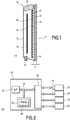
- the electronic control device 20 is shown schematically at the figure 2 .
- the electronic control device 20 comprises in particular a control box 30 situated at the upper part of the apparatus 10.
- the control box 30 comprises, for example, a microprocessor 32, a program memory 34 and at least one communication bus 36.
- the control unit 30 also includes a thermostat 38 for setting a set temperature of the apparatus 10.
- control unit 30 is connected to the electrical resistance 22 of the main heating element 12, as well as to the electrical resistance of the secondary heating element 18.
- the electronic control device 20 also comprises a temperature sensor 42, located in the lower part of the apparatus 10 and connected to the control box 30.
- the probe 42 makes it possible to measure an ambient temperature.
- the electronic control device 20 is able to electrically supply the electrical resistances of the heating elements 12, 18. More specifically, the program memory contains a program 44 for regulating the power supply of said resistors, as a function of the ambient temperature measured by the probe 42 and the set temperature set at the thermostat 36.
- the primary heating element 12 has priority. In other words, as long as the power supply of the resistor 22 is less than a maximum power Pmax, the resistance of the secondary heating element 18 is not supplied with electricity.
- the maximum power Pmax for supplying the resistor 22 is between 20% and 80% of a total power of the apparatus 10.
- the power supply of the resistor 22 is preferably chrono-proportional type.
- the power supply is performed according to a succession of time cycles, of which a duration ⁇ is defined in the program 44.
- Each cycle comprises a first period of duration ⁇ 1 , during which the resistor is supplied with voltage, and a second period of duration ⁇ 2 , during which the resistor 22 is not powered.
- the duration ⁇ 1 , ⁇ 2 of each period depends on the difference between the ambient temperature and the set temperature.
- the supply voltage of the resistor 22 therefore has a crenellated time profile, in all or nothing.
- the electronic control device 20 comprises one or more thyristors 46 connected to said resistor 22.
- the thyristors 46 function as fast switches, whose opening and closing cycles control the power supply of the resistor 22.
- the rear face 26 of the facade 14 undergoes temporal variations in temperature.
- a temperature of said rear face 26 oscillates between a maximum value and a minimum value, according to an amplitude A 1 .
- the heat transferred to the rear face 26 is propagated through the facade 14 to the front face 24, according to an undulatory temporal profile.
- a temperature of said front face 24 oscillates between a maximum value and a minimum value, according to an amplitude A 2 .
- the temperature of the front face 24 is relatively stable, so that the amplitude A 2 is kept at a low value.
- the heat passing through the facade 14 between the rear faces 26 and front 24 can be likened to a thermal wave.
- a damping of said thermal wave at the front face 24 depends in particular on the thermal inertia of the material M forming the facade 14.
- a thermal capacity C p , a thermal conduction ⁇ and a density ⁇ of the material M of the facade 14 are determined, in particular by conventional methods for measuring the thermophysical properties of the materials.
- a pulsation ⁇ of the electrical supply of the electrical resistance is determined.
- ⁇ 2 ⁇ / ⁇
- a minimum value Emin of the thickness E, between the front face 24 and the rear face 26 of the facade is determined.
- the Emin value depends on the minimum damping desired for the thermal wave passing through the facade. In other words, the value Emin depends on the maximum permissible value for the ratio A 2 / A 1 .
- Emin B ⁇ ⁇ . VS p . ⁇
- said maximum value of A 2 / A 1 is 2% (ie 1/50), which corresponds to a minimum damping of 98%.
- B ln 50 . 2
- the thickness E of the facade 14 must be chosen greater than the value Emin thus obtained.
- the sizing method also has a step of determining a maximum value Emax of the thickness of the facade 14, in order to limit the duration of rise in temperature. Said step of determining the Emax value will now be described.
- the maximum electrical power Pmax which can be supplied to the electrical resistance 22, is determined.
- a surface S of the front face 24 of the facade 14 is also determined. It is the surface capable of emitting infrared radiation under the effect of an increase in temperature of the material M.
- a temperature difference ⁇ T is also determined, corresponding to the desired maximum rise in temperature for the facade 14.
- ⁇ T is between 50 ° C. and 80 ° C. and more preferably equal to 70 ° C.
- t is between 45 minutes and 75 minutes and more preferably equal to 1 hour.
- Emax Pmax . t S . ⁇ . VS p . DT
- the thickness E of the facade 14 must be chosen lower than the value Emax thus obtained.
- the calculated value Emin must be less than or equal to the calculated value Emax.
- the respect or not of this inequality depends on one hand on the parameters C p , ⁇ and ⁇ of the material M, on the other hand on the surface S of the facade 14.
- a method of designing the heater 10, relating to the choice of the material M of the facade 14, will now be described.
- This method relating to the choice of the material M is for example implemented as a preliminary step of the sizing method previously described.
- a plurality of emissive materials M i is preselected. For each of said emissive materials M i , the thermal capacity C p , the thermal conduction ⁇ and the density ⁇ are determined as previously described.
- a desired maximum value Smax of the surface S of the facade 14 is determined, in particular according to the desired use and design for the apparatus 10.
- each of the preselected emissive materials M i corresponds to the inequation (3): B ⁇ ⁇ ⁇ Pmax . t Smax . DT . ⁇ ⁇ . Pc B being a constant depending on the maximum permissible value for the ratio A 2 / A 1 previously described.
- the material M of the facade 14 can then be chosen from the materials M i which correspond to the equation (3) above.
- the materials Mi usable are such that Emin ⁇ Emax, equivalent to the inequation (3).
Landscapes
- Engineering & Computer Science (AREA)
- Chemical & Material Sciences (AREA)
- Combustion & Propulsion (AREA)
- Mechanical Engineering (AREA)
- General Engineering & Computer Science (AREA)
- Central Heating Systems (AREA)
- Electric Stoves And Ranges (AREA)
Applications Claiming Priority (1)
| Application Number | Priority Date | Filing Date | Title |
|---|---|---|---|
| FR1661853A FR3059762B1 (fr) | 2016-12-02 | 2016-12-02 | Procede de conception d'un appareil de chauffage rayonnant et appareil de chauffage associe |
Publications (2)
| Publication Number | Publication Date |
|---|---|
| EP3339740A2 true EP3339740A2 (de) | 2018-06-27 |
| EP3339740A3 EP3339740A3 (de) | 2018-11-14 |
Family
ID=59649739
Family Applications (1)
| Application Number | Title | Priority Date | Filing Date |
|---|---|---|---|
| EP17205288.8A Withdrawn EP3339740A3 (de) | 2016-12-02 | 2017-12-04 | Entwurfverfahren für strahlungsheizgerät, und entsprechendes heizgerät |
Country Status (2)
| Country | Link |
|---|---|
| EP (1) | EP3339740A3 (de) |
| FR (1) | FR3059762B1 (de) |
Family Cites Families (4)
| Publication number | Priority date | Publication date | Assignee | Title |
|---|---|---|---|---|
| FR2908261B1 (fr) * | 2006-11-03 | 2014-08-15 | Atlantic Industrie Sas | "panneau chauffant etanche et unidirectionnel pour radiateur electrique et radiateur electrique incluant un tel panneau" |
| EP2549191B1 (de) * | 2011-07-19 | 2013-09-11 | Paul Baltes | Natursteinheizkörper |
| FR3004240B1 (fr) * | 2013-04-03 | 2018-02-02 | Societe Muller & Cie | Appareil de chauffage avec dispositif de securite |
| FR3032262B1 (fr) * | 2015-01-30 | 2017-01-20 | Thermor Pacific | Appareil de chauffage electrique de faible epaisseur thermiquement inertiel et reactif |
-
2016
- 2016-12-02 FR FR1661853A patent/FR3059762B1/fr active Active
-
2017
- 2017-12-04 EP EP17205288.8A patent/EP3339740A3/de not_active Withdrawn
Also Published As
| Publication number | Publication date |
|---|---|
| FR3059762A1 (fr) | 2018-06-08 |
| EP3339740A3 (de) | 2018-11-14 |
| FR3059762B1 (fr) | 2019-05-17 |
Similar Documents
| Publication | Publication Date | Title |
|---|---|---|
| EP0412875B1 (de) | Temperaturmessvorrichtung für Induktionskochgerät und Gerät mit einer solchen Vorrichtung | |
| US20130313245A1 (en) | Wire mesh thermal radiative element and use in a radiative oven | |
| EP3009761B1 (de) | Elektrische heizvorrichtung und heizsystem | |
| US20150334775A1 (en) | High speed oven including wire mesh heating elements | |
| JP2021521498A (ja) | 電熱放射管温度制御装置とその制御方法 | |
| FR2948253A1 (fr) | Dispositif de chauffe par induction | |
| EP3339740A2 (de) | Entwurfverfahren für strahlungsheizgerät, und entsprechendes heizgerät | |
| EP2967249B1 (de) | Flüssigkeitserhitzer mit drahtgitter-erwärmungssegment | |
| FR3045139B1 (fr) | Chauffe eau plat domestique a resistances indirectes immergees | |
| CA2914827C (fr) | Appareil de chauffage comprenant un materiau a changement de phase | |
| GB2360591A (en) | Temperature sensor for use in a cooking appliance | |
| CA3044435A1 (fr) | Appareil de chauffage de type radiateur electrique ayant au moins un corps de chauffe rayonnant integrant deux elements blindes a corps resistifs fonctionnant sous courant alternatif et sous courant continu | |
| FR3015011A1 (fr) | Procede de regulation d'un appareil de chauffage par rayonnement et convection combines | |
| CN106867759A (zh) | 酿酒用温控装置及其温控方法 | |
| FR3032262A1 (fr) | Appareil de chauffage electrique de faible epaisseur thermiquement inertiel et reactif | |
| CN120857297B (zh) | 一种基于ptc电加热器温度均匀控制系统及方法 | |
| CN222166925U (zh) | 铁铬铝合金丝的热效率测试系统及其加热炉 | |
| EP0025756B1 (de) | Regelungsschaltung für die Temperatur eines Backofens, insbesondere zum häuslichen Gebrauch | |
| FR3088702A1 (fr) | Procede de chauffage d'un local par panneau vitre chauffant et systeme associe | |
| FR3027183B1 (fr) | Dispositif pour l’alimentation d’un chauffage electrique | |
| FR2556450A1 (fr) | Appareil de chauffage de locaux | |
| FR2875369A1 (fr) | Dispositif formant corps de chauffe | |
| EP4600561A1 (de) | Flüssigkeitsheizkörper mit externem heizkörper | |
| FR3040092A1 (fr) | Dispositif electronique permettant la commande d'un chauffage electrique utilisant un capteur de temperature influence par les elements chauffants | |
| US20060133446A1 (en) | Method of defining the emission coefficient of a surface to be heated |
Legal Events
| Date | Code | Title | Description |
|---|---|---|---|
| PUAI | Public reference made under article 153(3) epc to a published international application that has entered the european phase |
Free format text: ORIGINAL CODE: 0009012 |
|
| AK | Designated contracting states |
Kind code of ref document: A2 Designated state(s): AL AT BE BG CH CY CZ DE DK EE ES FI FR GB GR HR HU IE IS IT LI LT LU LV MC MK MT NL NO PL PT RO RS SE SI SK SM TR |
|
| AX | Request for extension of the european patent |
Extension state: BA ME |
|
| RIC1 | Information provided on ipc code assigned before grant |
Ipc: F24C 7/04 20060101AFI20180901BHEP |
|
| PUAL | Search report despatched |
Free format text: ORIGINAL CODE: 0009013 |
|
| RIC1 | Information provided on ipc code assigned before grant |
Ipc: F24C 7/04 20060101AFI20181003BHEP |
|
| AK | Designated contracting states |
Kind code of ref document: A3 Designated state(s): AL AT BE BG CH CY CZ DE DK EE ES FI FR GB GR HR HU IE IS IT LI LT LU LV MC MK MT NL NO PL PT RO RS SE SI SK SM TR |
|
| AX | Request for extension of the european patent |
Extension state: BA ME |
|
| RIC1 | Information provided on ipc code assigned before grant |
Ipc: F24C 7/04 20060101AFI20181005BHEP |
|
| 17P | Request for examination filed |
Effective date: 20190417 |
|
| RBV | Designated contracting states (corrected) |
Designated state(s): AL AT BE BG CH CY CZ DE DK EE ES FI FR GB GR HR HU IE IS IT LI LT LU LV MC MK MT NL NO PL PT RO RS SE SI SK SM TR |
|
| GRAP | Despatch of communication of intention to grant a patent |
Free format text: ORIGINAL CODE: EPIDOSNIGR1 |
|
| INTG | Intention to grant announced |
Effective date: 20200109 |
|
| GRAS | Grant fee paid |
Free format text: ORIGINAL CODE: EPIDOSNIGR3 |
|
| STAA | Information on the status of an ep patent application or granted ep patent |
Free format text: STATUS: THE APPLICATION IS DEEMED TO BE WITHDRAWN |
|
| 18D | Application deemed to be withdrawn |
Effective date: 20200701 |