EP3339764A1 - Vorrichtung zur erwärmung eines zimmers, montierbares modulares heizsystem damit, verfahren zu dessen herstellung und bausatz zu dessen herstellung - Google Patents
Vorrichtung zur erwärmung eines zimmers, montierbares modulares heizsystem damit, verfahren zu dessen herstellung und bausatz zu dessen herstellung Download PDFInfo
- Publication number
- EP3339764A1 EP3339764A1 EP17207931.1A EP17207931A EP3339764A1 EP 3339764 A1 EP3339764 A1 EP 3339764A1 EP 17207931 A EP17207931 A EP 17207931A EP 3339764 A1 EP3339764 A1 EP 3339764A1
- Authority
- EP
- European Patent Office
- Prior art keywords
- heating
- modules
- cross members
- upright member
- room according
- Prior art date
- Legal status (The legal status is an assumption and is not a legal conclusion. Google has not performed a legal analysis and makes no representation as to the accuracy of the status listed.)
- Granted
Links
Images


Classifications
-
- F—MECHANICAL ENGINEERING; LIGHTING; HEATING; WEAPONS; BLASTING
- F24—HEATING; RANGES; VENTILATING
- F24H—FLUID HEATERS, e.g. WATER OR AIR HEATERS, HAVING HEAT-GENERATING MEANS, e.g. HEAT PUMPS, IN GENERAL
- F24H3/00—Air heaters
- F24H3/002—Air heaters using electric energy supply
-
- A—HUMAN NECESSITIES
- A47—FURNITURE; DOMESTIC ARTICLES OR APPLIANCES; COFFEE MILLS; SPICE MILLS; SUCTION CLEANERS IN GENERAL
- A47K—SANITARY EQUIPMENT; ACCESSORIES THEREFOR, e.g. TOILET ACCESSORIES
- A47K10/00—Body-drying implements; Toilet paper; Holders therefor
- A47K10/04—Towel racks; Towel rails; Towel rods; Towel rolls, e.g. rotatable
- A47K10/06—Towel racks; Towel rails; Towel rods; Towel rolls, e.g. rotatable combined with means for drying towels
-
- F—MECHANICAL ENGINEERING; LIGHTING; HEATING; WEAPONS; BLASTING
- F24—HEATING; RANGES; VENTILATING
- F24D—DOMESTIC- OR SPACE-HEATING SYSTEMS, e.g. CENTRAL HEATING SYSTEMS; DOMESTIC HOT-WATER SUPPLY SYSTEMS; ELEMENTS OR COMPONENTS THEREFOR
- F24D13/00—Electric heating systems
- F24D13/02—Electric heating systems solely using resistance heating, e.g. underfloor heating
- F24D13/022—Electric heating systems solely using resistance heating, e.g. underfloor heating resistances incorporated in construction elements
-
- F—MECHANICAL ENGINEERING; LIGHTING; HEATING; WEAPONS; BLASTING
- F24—HEATING; RANGES; VENTILATING
- F24H—FLUID HEATERS, e.g. WATER OR AIR HEATERS, HAVING HEAT-GENERATING MEANS, e.g. HEAT PUMPS, IN GENERAL
- F24H3/00—Air heaters
- F24H3/002—Air heaters using electric energy supply
- F24H3/004—Air heaters using electric energy supply with a closed circuit for a heat transfer liquid
-
- F—MECHANICAL ENGINEERING; LIGHTING; HEATING; WEAPONS; BLASTING
- F28—HEAT EXCHANGE IN GENERAL
- F28D—HEAT-EXCHANGE APPARATUS, NOT PROVIDED FOR IN ANOTHER SUBCLASS, IN WHICH THE HEAT-EXCHANGE MEDIA DO NOT COME INTO DIRECT CONTACT
- F28D1/00—Heat-exchange apparatus having stationary conduit assemblies for one heat-exchange medium only, the media being in contact with different sides of the conduit wall, in which the other heat-exchange medium is a large body of fluid, e.g. domestic or motor car radiators
- F28D1/02—Heat-exchange apparatus having stationary conduit assemblies for one heat-exchange medium only, the media being in contact with different sides of the conduit wall, in which the other heat-exchange medium is a large body of fluid, e.g. domestic or motor car radiators with heat-exchange conduits immersed in the body of fluid
- F28D1/04—Heat-exchange apparatus having stationary conduit assemblies for one heat-exchange medium only, the media being in contact with different sides of the conduit wall, in which the other heat-exchange medium is a large body of fluid, e.g. domestic or motor car radiators with heat-exchange conduits immersed in the body of fluid with tubular conduits
- F28D1/047—Heat-exchange apparatus having stationary conduit assemblies for one heat-exchange medium only, the media being in contact with different sides of the conduit wall, in which the other heat-exchange medium is a large body of fluid, e.g. domestic or motor car radiators with heat-exchange conduits immersed in the body of fluid with tubular conduits the conduits being bent, e.g. in a serpentine or zig-zag
- F28D1/0475—Heat-exchange apparatus having stationary conduit assemblies for one heat-exchange medium only, the media being in contact with different sides of the conduit wall, in which the other heat-exchange medium is a large body of fluid, e.g. domestic or motor car radiators with heat-exchange conduits immersed in the body of fluid with tubular conduits the conduits being bent, e.g. in a serpentine or zig-zag the conduits having a single U-bend
- F28D1/0476—Heat-exchange apparatus having stationary conduit assemblies for one heat-exchange medium only, the media being in contact with different sides of the conduit wall, in which the other heat-exchange medium is a large body of fluid, e.g. domestic or motor car radiators with heat-exchange conduits immersed in the body of fluid with tubular conduits the conduits being bent, e.g. in a serpentine or zig-zag the conduits having a single U-bend the conduits having a non-circular cross-section
-
- F—MECHANICAL ENGINEERING; LIGHTING; HEATING; WEAPONS; BLASTING
- F28—HEAT EXCHANGE IN GENERAL
- F28D—HEAT-EXCHANGE APPARATUS, NOT PROVIDED FOR IN ANOTHER SUBCLASS, IN WHICH THE HEAT-EXCHANGE MEDIA DO NOT COME INTO DIRECT CONTACT
- F28D1/00—Heat-exchange apparatus having stationary conduit assemblies for one heat-exchange medium only, the media being in contact with different sides of the conduit wall, in which the other heat-exchange medium is a large body of fluid, e.g. domestic or motor car radiators
- F28D1/02—Heat-exchange apparatus having stationary conduit assemblies for one heat-exchange medium only, the media being in contact with different sides of the conduit wall, in which the other heat-exchange medium is a large body of fluid, e.g. domestic or motor car radiators with heat-exchange conduits immersed in the body of fluid
- F28D1/04—Heat-exchange apparatus having stationary conduit assemblies for one heat-exchange medium only, the media being in contact with different sides of the conduit wall, in which the other heat-exchange medium is a large body of fluid, e.g. domestic or motor car radiators with heat-exchange conduits immersed in the body of fluid with tubular conduits
- F28D1/053—Heat-exchange apparatus having stationary conduit assemblies for one heat-exchange medium only, the media being in contact with different sides of the conduit wall, in which the other heat-exchange medium is a large body of fluid, e.g. domestic or motor car radiators with heat-exchange conduits immersed in the body of fluid with tubular conduits the conduits being straight
- F28D1/05308—Assemblies of conduits connected side by side or with individual headers, e.g. section type radiators
-
- F—MECHANICAL ENGINEERING; LIGHTING; HEATING; WEAPONS; BLASTING
- F28—HEAT EXCHANGE IN GENERAL
- F28D—HEAT-EXCHANGE APPARATUS, NOT PROVIDED FOR IN ANOTHER SUBCLASS, IN WHICH THE HEAT-EXCHANGE MEDIA DO NOT COME INTO DIRECT CONTACT
- F28D1/00—Heat-exchange apparatus having stationary conduit assemblies for one heat-exchange medium only, the media being in contact with different sides of the conduit wall, in which the other heat-exchange medium is a large body of fluid, e.g. domestic or motor car radiators
- F28D1/02—Heat-exchange apparatus having stationary conduit assemblies for one heat-exchange medium only, the media being in contact with different sides of the conduit wall, in which the other heat-exchange medium is a large body of fluid, e.g. domestic or motor car radiators with heat-exchange conduits immersed in the body of fluid
- F28D1/04—Heat-exchange apparatus having stationary conduit assemblies for one heat-exchange medium only, the media being in contact with different sides of the conduit wall, in which the other heat-exchange medium is a large body of fluid, e.g. domestic or motor car radiators with heat-exchange conduits immersed in the body of fluid with tubular conduits
- F28D1/053—Heat-exchange apparatus having stationary conduit assemblies for one heat-exchange medium only, the media being in contact with different sides of the conduit wall, in which the other heat-exchange medium is a large body of fluid, e.g. domestic or motor car radiators with heat-exchange conduits immersed in the body of fluid with tubular conduits the conduits being straight
- F28D1/0535—Heat-exchange apparatus having stationary conduit assemblies for one heat-exchange medium only, the media being in contact with different sides of the conduit wall, in which the other heat-exchange medium is a large body of fluid, e.g. domestic or motor car radiators with heat-exchange conduits immersed in the body of fluid with tubular conduits the conduits being straight the conduits having a non-circular cross-section
- F28D1/05358—Assemblies of conduits connected side by side or with individual headers, e.g. section type radiators
-
- F—MECHANICAL ENGINEERING; LIGHTING; HEATING; WEAPONS; BLASTING
- F28—HEAT EXCHANGE IN GENERAL
- F28D—HEAT-EXCHANGE APPARATUS, NOT PROVIDED FOR IN ANOTHER SUBCLASS, IN WHICH THE HEAT-EXCHANGE MEDIA DO NOT COME INTO DIRECT CONTACT
- F28D1/00—Heat-exchange apparatus having stationary conduit assemblies for one heat-exchange medium only, the media being in contact with different sides of the conduit wall, in which the other heat-exchange medium is a large body of fluid, e.g. domestic or motor car radiators
- F28D1/02—Heat-exchange apparatus having stationary conduit assemblies for one heat-exchange medium only, the media being in contact with different sides of the conduit wall, in which the other heat-exchange medium is a large body of fluid, e.g. domestic or motor car radiators with heat-exchange conduits immersed in the body of fluid
- F28D1/04—Heat-exchange apparatus having stationary conduit assemblies for one heat-exchange medium only, the media being in contact with different sides of the conduit wall, in which the other heat-exchange medium is a large body of fluid, e.g. domestic or motor car radiators with heat-exchange conduits immersed in the body of fluid with tubular conduits
- F28D1/053—Heat-exchange apparatus having stationary conduit assemblies for one heat-exchange medium only, the media being in contact with different sides of the conduit wall, in which the other heat-exchange medium is a large body of fluid, e.g. domestic or motor car radiators with heat-exchange conduits immersed in the body of fluid with tubular conduits the conduits being straight
- F28D1/0535—Heat-exchange apparatus having stationary conduit assemblies for one heat-exchange medium only, the media being in contact with different sides of the conduit wall, in which the other heat-exchange medium is a large body of fluid, e.g. domestic or motor car radiators with heat-exchange conduits immersed in the body of fluid with tubular conduits the conduits being straight the conduits having a non-circular cross-section
- F28D1/05366—Assemblies of conduits connected to common headers, e.g. core type radiators
-
- F—MECHANICAL ENGINEERING; LIGHTING; HEATING; WEAPONS; BLASTING
- F28—HEAT EXCHANGE IN GENERAL
- F28F—DETAILS OF HEAT-EXCHANGE AND HEAT-TRANSFER APPARATUS, OF GENERAL APPLICATION
- F28F9/00—Casings; Header boxes; Auxiliary supports for elements; Auxiliary members within casings
- F28F9/02—Header boxes; End plates
- F28F9/0219—Arrangements for sealing end plates into casing or header box; Header box sub-elements
- F28F9/0221—Header boxes or end plates formed by stacked elements
-
- F—MECHANICAL ENGINEERING; LIGHTING; HEATING; WEAPONS; BLASTING
- F28—HEAT EXCHANGE IN GENERAL
- F28F—DETAILS OF HEAT-EXCHANGE AND HEAT-TRANSFER APPARATUS, OF GENERAL APPLICATION
- F28F9/00—Casings; Header boxes; Auxiliary supports for elements; Auxiliary members within casings
- F28F9/02—Header boxes; End plates
- F28F9/0246—Arrangements for connecting header boxes with flow lines
- F28F9/0256—Arrangements for coupling connectors with flow lines
-
- F—MECHANICAL ENGINEERING; LIGHTING; HEATING; WEAPONS; BLASTING
- F28—HEAT EXCHANGE IN GENERAL
- F28F—DETAILS OF HEAT-EXCHANGE AND HEAT-TRANSFER APPARATUS, OF GENERAL APPLICATION
- F28F9/00—Casings; Header boxes; Auxiliary supports for elements; Auxiliary members within casings
- F28F9/02—Header boxes; End plates
- F28F9/04—Arrangements for sealing elements into header boxes or end plates
- F28F9/16—Arrangements for sealing elements into header boxes or end plates by permanent joints, e.g. by rolling
-
- F—MECHANICAL ENGINEERING; LIGHTING; HEATING; WEAPONS; BLASTING
- F24—HEATING; RANGES; VENTILATING
- F24D—DOMESTIC- OR SPACE-HEATING SYSTEMS, e.g. CENTRAL HEATING SYSTEMS; DOMESTIC HOT-WATER SUPPLY SYSTEMS; ELEMENTS OR COMPONENTS THEREFOR
- F24D2200/00—Heat sources or energy sources
- F24D2200/08—Electric heater
-
- F—MECHANICAL ENGINEERING; LIGHTING; HEATING; WEAPONS; BLASTING
- F24—HEATING; RANGES; VENTILATING
- F24D—DOMESTIC- OR SPACE-HEATING SYSTEMS, e.g. CENTRAL HEATING SYSTEMS; DOMESTIC HOT-WATER SUPPLY SYSTEMS; ELEMENTS OR COMPONENTS THEREFOR
- F24D2220/00—Components of central heating installations excluding heat sources
- F24D2220/20—Heat consumers
- F24D2220/2009—Radiators
- F24D2220/2036—Electric radiators
-
- Y—GENERAL TAGGING OF NEW TECHNOLOGICAL DEVELOPMENTS; GENERAL TAGGING OF CROSS-SECTIONAL TECHNOLOGIES SPANNING OVER SEVERAL SECTIONS OF THE IPC; TECHNICAL SUBJECTS COVERED BY FORMER USPC CROSS-REFERENCE ART COLLECTIONS [XRACs] AND DIGESTS
- Y02—TECHNOLOGIES OR APPLICATIONS FOR MITIGATION OR ADAPTATION AGAINST CLIMATE CHANGE
- Y02B—CLIMATE CHANGE MITIGATION TECHNOLOGIES RELATED TO BUILDINGS, e.g. HOUSING, HOUSE APPLIANCES OR RELATED END-USER APPLICATIONS
- Y02B30/00—Energy efficient heating, ventilation or air conditioning [HVAC]
Definitions
- the present invention relates to a device for heating a room.
- heating devices of various types have been developed, in particular electric or hot water radiators for heating a room and towel warmers for bathrooms.
- the technical task that the present invention sets itself is thus to provide a device for heating a room which enables the aforesaid technical drawbacks of the prior art to be overcome.
- one object of the invention is to provide a device for heating a room which simplifies production, packaging, warehouse storage, handling, transport and installation.
- Another object of the invention is to provide a device for heating a room which has extremely modest production and sale costs.
- Yet another object of the invention is to provide a device for heating a room which can be flexibly customised according to aesthetic tastes and specific technical requirements.
- Another object of the invention is to provide a device for heating a room which lends itself to simplifying maintenance and repairs.
- a device for heating a room characterised in that it has an assemblable modular structure comprising at least one upright member, a plurality of cross members, modules assemblable to one another for the connection of said cross members to said upright member and a heating circuit which extends along said upright member and said cross members and through said modules.
- a single upright member is provided.
- At least two upright members are provided, said plurality of cross members being disposed between them, and said connection modules being provided at each end of said cross members for the connection of said cross members to said two upright members.
- a stack of modules connected to one another in cascade fashion is positioned in a longitudinal cavity of said at least one upright member.
- said module has a shape mating that of said longitudinal cavity, which in turn has sliding guides for said module.
- said at least one upright member has, along the entire length thereof, an opening for the access of said end of said cross member to said longitudinal cavity.
- said module has a quick coupling hole for the end of said cross member.
- the heating circuit is fragmented into a plurality of segments connectible to one another.
- each module incorporates a segment of the heating circuit.
- the segments of the heating circuit are connected to one another in cascade fashion.
- said heating circuit comprises electrical resistance heating elements positioned in said cross members.
- said segments are segments of an electrical line for powering said heating elements.
- said modules are preferably made of an electrically insulating material in which said electrical line segment is encased.
- said heating circuit preferably has a manual switch mounted on said at least one upright member.
- the heating circuit instead comprises a monolithic element.
- said heating circuit preferably comprises a flexible heating cable that extends along said cross members, along said at least one upright member and through said modules.
- the heating circuit comprises a channelization containing a heat carrier fluid.
- said segments are channel segments of said channelization.
- the present invention also discloses a process for producing a device for heating a room made up of at least one upright member and a plurality of cross members containing within them a heating means, characterised in that the cross members are connected to the upright member by applying a connection module at the end of each cross member and introducing the modules in succession along a longitudinal cavity of the upright member, making the end of the cross member slide along a lateral opening of the upright member provided to enable access of the end of the cross members to the longitudinal cavity of the upright member.
- the present invention further discloses a kit for producing a device for heating a room, characterised in that it comprises at least one upright member, a plurality of cross members, a plurality of modules assemblable to one another for the connection of said cross members to said upright member, and a heating means present at least in said cross members.
- the heating device according to the invention is thus the result of the composition of modules, which enable a customisation of the product according to aesthetic tastes and specific technical needs.
- the product can be stored in a warehouse and transported with its components disassembled in order o be assembled later on the installation site.
- the packaging is also extremely compact, orderly and protected through the use of various compartments provided based on the type of components, so that it can be organised based on the installation sequence of each component.
- This boxing configuration especially in the case of manual packing, makes it possible to quickly visually check whether each individual component is present or not.
- Uncouplable quick coupling systems are advantageously provided for assembly of the product. For maintenance or repair, therefore, it is possible to disassemble the product with the same ease with which it was assembled and if necessary replace only the damaged or defective component.
- the modularity also offers the possibility of modifying the shape and size of the product, by adding to it and expanding it after the initial installation, for example in order to increase the installed heating capacity.
- the heating device according to the invention can have a manual adjustment and control system or an electronic one which can also be managed remotely via the Internet.
- the heating device according to the invention can incorporate a blower for the distribution of heat energy.
- the heating device according to the invention can be of the wall-mountable type or can be positioned anywhere and in this case it preferably has a supporting stand, for example a supporting stand having two housings at the top in which the lower ends of the two upright members can be inserted.
- the stand can be fitted with wheels to facilitate moving the device.
- the blower if provided, can in this case also be installed on the same supporting stand.
- the cross members and the upright members are metal profiles, for example made of aluminium alloy, and the connection modules are made of electrically insulating plastic.
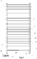
- Figures 1 - 3 , 6 - 8 show three versions of an electric towel warmer configured for fixed wall mounting, but the scope of the invention also comprises heating devices of another type: for example, figures 4 and 5 show a version of a hot water radiator.
- the radiators can be fixed or repositionable and are provided in the latter case with a supporting stand 54.
- the heating device 1 illustrated in figures 1 - 3 , 6 and 7 advantageously comprises an assemblable modular structure made up of two upright members 2, a plurality of cross members 3 disposed between the upright members 2, connection modules 6 for connecting the cross members 3 to the upright members 2, and a heating circuit 5 which extends along the upright members 2 and cross members 3 and through the modules 6.
- the modules 6 are provided at each of the two ends of each cross member 3.
- the longitudinal cavity 9 extends along the whole length of the upright member 2 and is accessible to the modules 6 from the bases 10 of the upright member 2 and to the cross member 3 from a lateral opening 11 of the upright member 2 which extends along the whole length of the upright member 2.
- the longitudinal cavity 9 of the upright member 2 has a shape mating that of the stack of modules 6 so as to permit the guided insertion of the modules 6 along the axis of the upright member 2 without modifying their orientation.
- the modules 6 engage by friction and sliding in the longitudinal cavity 9 of the upright member 2 and are guided along guides 9a, 11a inside the cavity 9 so as to maintain the position assumed at the end of the insertion thereof.
- the module 6 has a quick coupling hole 15 for the end of the cross member 3.
- the hole 15 has a bottom 16 and a side wall 16a provided with a snap tooth 18 with which a slot 19 provided on the end of the cross member 3 engages.
- the heating circuit 5 in the example illustrated in figures 2 - 3 comprises electrical resistance heating elements 8 which extend longitudinally along an axial cavity 4 of the cross members 3.
- Each module 6 moreover incorporates a segment 7 of the heating circuit 5.
- the segments 7 of the heating circuit 5 provided in the modules 6 of each stack of modules 6 are connected to one another in cascade fashion.
- the electrical resistance heating element 8 is configured to receive the electrical power supply from only one end, the segments 7 in the stack of modules 6 positioned in the upright member 2 closest to that end will be active, whilst the segments 7 in the stack of modules 6 positioned in the upright member 2 farthest from that end will be inactive.
- the segments 7 in this embodiment of the invention are segments of an electrical power line supplying the heating elements 8.
- the segments 7 of the electrical power line are made up of conductive wires or conductive tracks.
- the segments 7 can be covered with a sheath of electrically insulating material or can be encased in the body of the module 6, which in this case must be made of electrically insulating material.
- male and female electrical connectors 13, 14 are provided for the electrical connection between the segments 7 of the adjacent modules 6.
- male and female electrical connectors 21, 22 positioned on the end of the electrical resistance heating element 8 and on the bottom 16 of the hole 15 for housing the end of the cross member 3.
- the electrical line which powers the heating means 5 has, finally, a manual switch 20 mounted on an upright member 2.
- a module 6 is mounted on each end of the first cross member 3 by introducing the end of the cross member 3 into the coupling hole 15 until the electrical connectors 21, 22 are engaged and the tooth 18 snaps into the slot 19.
- the two modules 6 are inserted from a base of the cavity 9 of the two upright members 2 and pushed one by one towards the opposite base of the cavity 9 of the two upright members 2.
- the modules 6 are slidingly guided with friction along the cavity 9 of the upright members 2, sliding along the guides 9a, 11a.
- the final position of the two modules 6 is defined by specific stops, for example a closure plate 50 and screws 51 inserted into specific channels 52.
- the modules 6 remain temporarily stationary in the final position as a result solely of the static friction that is created with the wall of the cavity 9 of the upright members 2 of the guides 9a, 11a.
- connection of the electrical line supplying power to the heating elements 8 with an electrical source external to the device 1 can be made via the electrical connectors 13, 14 of the terminal modules 6 of the two stacks of modules 6.
- the heating circuit 5 in this case comprises a flexible heating cable 40 which extends along the cross members 3, along the upright members 2 and through the modules 6.
- the modules 6 are provided with specific channels 41 for the free passage of the flexible heating cable 40.
- the heating cable 40 can be single or double to allow various levels of capacity to be managed.
- the assembly comprising the power cable 42 and heating cable 40 can be provided with a safety system consisting of a protective enclosure containing the plug 43, so as to assure that the assembly is connected to the power socket only when it has been installed inside the device. Assembly of the device 1 takes place in the following manner.
- the modules 6 are connected to the ends of the cross members 3.
- the cross members 3 with the associated modules 6 are fitted onto the cable 40 in succession, leaving a space between one assembly thus produced and the next one.
- the cable 40 in particular, is fitted into the axial cavity of the cross members 3 and the passage channel 41 of the modules 6.
- the cable 40 is shaped with angles of 180 ° in portions of cable 40 external to the cross members 3 and one cross member 3 at a time is connected to the upright members 2 by inserting the respective modules 6 into the cavity of the upright members 2.
- connection modules 6 for connecting to the upright member 2.
- the heating circuit 5 comprises a flexible heating cable 40 which extends along the cross members 3, along the upright member 2 and through specific free passage channels 41 fashioned in the modules 6.
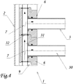
- FIGS. 4 and 5 show a heating device 1 that differs from the ones just described substantially in that there is envisaged a heating circuit 5 comprising a channelization containing a heat carrier fluid, for example water circulating in the internal cavity 30 of the cross members 3.
- a heat carrier fluid for example water circulating in the internal cavity 30 of the cross members 3.
- the device 1 comprises two upright members 2 and a plurality of cross members 3 disposed between the upright members 2 and connected to the upright members 2 by means of modules 6 provided at each of the two ends of each cross member 3.
- the modules 6 are engaged one by one with the next, forming a stack of modules 6 housed along a longitudinal cavity 9 which extends along the whole length of the upright member 2 and is accessible to the modules 6 from the bases of the upright member 2 and to the cross member 3 from a lateral opening of the upright member 2 which extends along the whole length of the upright member 2.
- the longitudinal cavity 9 of the upright member 2 has a shape mating that of the modules 6 so as permit the guided insertion thereof along the axis of the upright member 2 without modifying their orientation.
- segments 7 of the heating circuit 5 are channel segments of said channelization in fluid communication with the internal cavity 30 of the cross members 3.
- the segments 7 provided in the adjacent modules 6 in this case as well are connected to one another in cascade fashion.
- the heating device with an assemblable modular structure thus conceived is susceptible of numerous modifications and variants, all falling within the scope of the inventive concept.
- Special spacers can also be provided in order to manage variable distances and empty spaces between the cross members.
- the lower cross member can be configured for the insertion of an electronic control system and/or a blower.
- the upper or a central cross member can comprise specific systems for connection to accessories such as, for example, clothes racks, also rotatable ones.
- Special guide tracks 57 can be provided on the upright members 2 for the adjustable sliding of blocks 58 having a threaded hole for engaging a pin integral with a wall mounting bracket.
- Special threaded heads 56 can be provided for the connection to the plumbing system; these are screwed onto specific channels fashioned in the upright members 2.
- the heads can also include an extension towards the wall which enables the wall mounting of the device.
- the materials used, as well as the dimensions, may in practice be of any type, according to needs and the state of the art.
Landscapes
- Engineering & Computer Science (AREA)
- Physics & Mathematics (AREA)
- Thermal Sciences (AREA)
- Mechanical Engineering (AREA)
- General Engineering & Computer Science (AREA)
- Chemical & Material Sciences (AREA)
- Combustion & Propulsion (AREA)
- Health & Medical Sciences (AREA)
- Public Health (AREA)
- Central Heating Systems (AREA)
Applications Claiming Priority (1)
| Application Number | Priority Date | Filing Date | Title |
|---|---|---|---|
| IT102016000129225A IT201600129225A1 (it) | 2016-12-21 | 2016-12-21 | Dispositivo per il riscaldamento di un ambiente |
Publications (2)
| Publication Number | Publication Date |
|---|---|
| EP3339764A1 true EP3339764A1 (de) | 2018-06-27 |
| EP3339764B1 EP3339764B1 (de) | 2020-08-12 |
Family
ID=58609813
Family Applications (1)
| Application Number | Title | Priority Date | Filing Date |
|---|---|---|---|
| EP17207931.1A Active EP3339764B1 (de) | 2016-12-21 | 2017-12-18 | Vorrichtung zur erwärmung eines zimmers, montierbares modulares heizsystem damit und verfahren zu dessen herstellung |
Country Status (3)
| Country | Link |
|---|---|
| EP (1) | EP3339764B1 (de) |
| ES (1) | ES2824503T3 (de) |
| IT (1) | IT201600129225A1 (de) |
Cited By (2)
| Publication number | Priority date | Publication date | Assignee | Title |
|---|---|---|---|---|
| EP3985341A1 (de) * | 2020-10-16 | 2022-04-20 | LG Electronics Inc. | Wärmetauscher und wärmetauscherherstellungsverfahren |
| WO2024209337A1 (en) | 2023-04-07 | 2024-10-10 | Emmesteel S.R.L. | Electric heating device with open structure and power regulator |
Citations (8)
| Publication number | Priority date | Publication date | Assignee | Title |
|---|---|---|---|---|
| GB2212037A (en) * | 1987-11-06 | 1989-07-12 | Kelvin Pearce | Electrically heated towel rail |
| US5236095A (en) * | 1992-07-17 | 1993-08-17 | Krizka Allen J | Bumper rack assembly |
| GB2365114A (en) * | 2000-07-25 | 2002-02-13 | Dahll Ltd | A modular towel rail |
| WO2007137305A2 (en) * | 2006-05-24 | 2007-11-29 | Andrew Keith Maclaren-Taylor | A towel rail |
| GB2451109A (en) * | 2007-07-18 | 2009-01-21 | Basic Holdings | Electrically heated towel rack |
| FR2985654A1 (fr) * | 2012-01-16 | 2013-07-19 | Texas De France | Radiateur seche-serviettes dont au moins un barreau porte-serviette integre un dissipateur thermique dans lequel est loge un cordon electrique chauffant |
| EP3009057A1 (de) * | 2014-10-14 | 2016-04-20 | Tonon Forty S.p.a. | Handtucherwärmungskonstruktion mit hoher wärmeeffizienz |
| EP3096094A1 (de) * | 2015-05-21 | 2016-11-23 | Texas De France | Elektrisches heizgerät für den hausgebrauch, das mindestens einen flachen hohlprofilstab umfasst, in dem ein elektrisches heizelement untergebracht ist |
-
2016
- 2016-12-21 IT IT102016000129225A patent/IT201600129225A1/it unknown
-
2017
- 2017-12-18 ES ES17207931T patent/ES2824503T3/es active Active
- 2017-12-18 EP EP17207931.1A patent/EP3339764B1/de active Active
Patent Citations (8)
| Publication number | Priority date | Publication date | Assignee | Title |
|---|---|---|---|---|
| GB2212037A (en) * | 1987-11-06 | 1989-07-12 | Kelvin Pearce | Electrically heated towel rail |
| US5236095A (en) * | 1992-07-17 | 1993-08-17 | Krizka Allen J | Bumper rack assembly |
| GB2365114A (en) * | 2000-07-25 | 2002-02-13 | Dahll Ltd | A modular towel rail |
| WO2007137305A2 (en) * | 2006-05-24 | 2007-11-29 | Andrew Keith Maclaren-Taylor | A towel rail |
| GB2451109A (en) * | 2007-07-18 | 2009-01-21 | Basic Holdings | Electrically heated towel rack |
| FR2985654A1 (fr) * | 2012-01-16 | 2013-07-19 | Texas De France | Radiateur seche-serviettes dont au moins un barreau porte-serviette integre un dissipateur thermique dans lequel est loge un cordon electrique chauffant |
| EP3009057A1 (de) * | 2014-10-14 | 2016-04-20 | Tonon Forty S.p.a. | Handtucherwärmungskonstruktion mit hoher wärmeeffizienz |
| EP3096094A1 (de) * | 2015-05-21 | 2016-11-23 | Texas De France | Elektrisches heizgerät für den hausgebrauch, das mindestens einen flachen hohlprofilstab umfasst, in dem ein elektrisches heizelement untergebracht ist |
Cited By (3)
| Publication number | Priority date | Publication date | Assignee | Title |
|---|---|---|---|---|
| EP3985341A1 (de) * | 2020-10-16 | 2022-04-20 | LG Electronics Inc. | Wärmetauscher und wärmetauscherherstellungsverfahren |
| US11940219B2 (en) | 2020-10-16 | 2024-03-26 | Lg Electronics Inc. | Heat exchanger and heat exchanger manufacturing method |
| WO2024209337A1 (en) | 2023-04-07 | 2024-10-10 | Emmesteel S.R.L. | Electric heating device with open structure and power regulator |
Also Published As
| Publication number | Publication date |
|---|---|
| ES2824503T3 (es) | 2021-05-12 |
| IT201600129225A1 (it) | 2018-06-21 |
| EP3339764B1 (de) | 2020-08-12 |
Similar Documents
| Publication | Publication Date | Title |
|---|---|---|
| US7648379B2 (en) | Modular electrical distribution system for a building | |
| CN201898284U (zh) | 用于电机控制中心的总线支撑系统以及总线支撑固定件 | |
| US6336691B1 (en) | Storage cabinet for electronic devices | |
| US20160286674A1 (en) | Function component upper part for a component construction system | |
| US8172589B2 (en) | Modular electrical distribution system for a building | |
| US6777611B2 (en) | Switch/power drop unit for modular wiring system | |
| US6207895B1 (en) | Device box for wall mounted communications apparatus | |
| ES2637562A1 (es) | Módulo para toma de corriente deslizable | |
| US9057513B2 (en) | Electrical assembly for connecting components of a lighting system for illuminating store shelving | |
| US20110195600A1 (en) | Distribution strip and equipment cabinet | |
| US9997932B2 (en) | Charge cabinet and storage device thereof | |
| ES2533705T3 (es) | Módulo de soporte de fijación para componentes de fabricación y/o de montaje de una instalación de procesamiento así como una unidad de procesamiento equipada con dicho módulo de soporte | |
| EP3339764B1 (de) | Vorrichtung zur erwärmung eines zimmers, montierbares modulares heizsystem damit und verfahren zu dessen herstellung | |
| ES1068230U (es) | Enchufes con escobillas y patillas de deslizamiento por guias electricas para instalaciones del hogar, comercio o industria. | |
| HK1252750B (zh) | 电能存储模块 | |
| US2897410A (en) | Plug-in type circuit breaker panelboard | |
| US10411417B2 (en) | Modular wall system and panel element for use in such a system | |
| ES2882710T3 (es) | Dispositivo de distribución de corriente, en particular en un armario o panel eléctrico | |
| EP1249913A3 (de) | Verteilergehäuse mit Anschlussteilen | |
| JP3113266U (ja) | ユニット式分電盤 | |
| US7927133B2 (en) | Element for coupling a lighting appliance to an electric rail | |
| CN105490052B (zh) | 用于插座的多位置的机构 | |
| US20160372879A1 (en) | Information Technology Racks Having Integrated Bus Plugs and Related Systems and Busways | |
| GB2082395A (en) | Pitch variators for sub-rack connectors | |
| CN207134645U (zh) | 智能模块化低压配电柜 |
Legal Events
| Date | Code | Title | Description |
|---|---|---|---|
| PUAI | Public reference made under article 153(3) epc to a published international application that has entered the european phase |
Free format text: ORIGINAL CODE: 0009012 |
|
| STAA | Information on the status of an ep patent application or granted ep patent |
Free format text: STATUS: THE APPLICATION HAS BEEN PUBLISHED |
|
| AK | Designated contracting states |
Kind code of ref document: A1 Designated state(s): AL AT BE BG CH CY CZ DE DK EE ES FI FR GB GR HR HU IE IS IT LI LT LU LV MC MK MT NL NO PL PT RO RS SE SI SK SM TR |
|
| AX | Request for extension of the european patent |
Extension state: BA ME |
|
| STAA | Information on the status of an ep patent application or granted ep patent |
Free format text: STATUS: REQUEST FOR EXAMINATION WAS MADE |
|
| 17P | Request for examination filed |
Effective date: 20181211 |
|
| RBV | Designated contracting states (corrected) |
Designated state(s): AL AT BE BG CH CY CZ DE DK EE ES FI FR GB GR HR HU IE IS IT LI LT LU LV MC MK MT NL NO PL PT RO RS SE SI SK SM TR |
|
| GRAP | Despatch of communication of intention to grant a patent |
Free format text: ORIGINAL CODE: EPIDOSNIGR1 |
|
| STAA | Information on the status of an ep patent application or granted ep patent |
Free format text: STATUS: GRANT OF PATENT IS INTENDED |
|
| RIC1 | Information provided on ipc code assigned before grant |
Ipc: H05B 3/54 20060101ALI20200214BHEP Ipc: F28D 1/053 20060101ALI20200214BHEP Ipc: F24D 13/02 20060101ALI20200214BHEP Ipc: A47K 10/06 20060101ALI20200214BHEP Ipc: F24H 3/00 20060101AFI20200214BHEP |
|
| INTG | Intention to grant announced |
Effective date: 20200313 |
|
| GRAS | Grant fee paid |
Free format text: ORIGINAL CODE: EPIDOSNIGR3 |
|
| GRAA | (expected) grant |
Free format text: ORIGINAL CODE: 0009210 |
|
| STAA | Information on the status of an ep patent application or granted ep patent |
Free format text: STATUS: THE PATENT HAS BEEN GRANTED |
|
| AK | Designated contracting states |
Kind code of ref document: B1 Designated state(s): AL AT BE BG CH CY CZ DE DK EE ES FI FR GB GR HR HU IE IS IT LI LT LU LV MC MK MT NL NO PL PT RO RS SE SI SK SM TR |
|
| REG | Reference to a national code |
Ref country code: CH Ref legal event code: EP |
|
| REG | Reference to a national code |
Ref country code: IE Ref legal event code: FG4D |
|
| REG | Reference to a national code |
Ref country code: DE Ref legal event code: R096 Ref document number: 602017021480 Country of ref document: DE |
|
| REG | Reference to a national code |
Ref country code: AT Ref legal event code: REF Ref document number: 1301934 Country of ref document: AT Kind code of ref document: T Effective date: 20200915 |
|
| REG | Reference to a national code |
Ref country code: SE Ref legal event code: TRGR |
|
| REG | Reference to a national code |
Ref country code: LT Ref legal event code: MG4D |
|
| REG | Reference to a national code |
Ref country code: NL Ref legal event code: MP Effective date: 20200812 |
|
| PG25 | Lapsed in a contracting state [announced via postgrant information from national office to epo] |
Ref country code: NO Free format text: LAPSE BECAUSE OF FAILURE TO SUBMIT A TRANSLATION OF THE DESCRIPTION OR TO PAY THE FEE WITHIN THE PRESCRIBED TIME-LIMIT Effective date: 20201112 Ref country code: GR Free format text: LAPSE BECAUSE OF FAILURE TO SUBMIT A TRANSLATION OF THE DESCRIPTION OR TO PAY THE FEE WITHIN THE PRESCRIBED TIME-LIMIT Effective date: 20201113 Ref country code: LT Free format text: LAPSE BECAUSE OF FAILURE TO SUBMIT A TRANSLATION OF THE DESCRIPTION OR TO PAY THE FEE WITHIN THE PRESCRIBED TIME-LIMIT Effective date: 20200812 Ref country code: BG Free format text: LAPSE BECAUSE OF FAILURE TO SUBMIT A TRANSLATION OF THE DESCRIPTION OR TO PAY THE FEE WITHIN THE PRESCRIBED TIME-LIMIT Effective date: 20201112 Ref country code: HR Free format text: LAPSE BECAUSE OF FAILURE TO SUBMIT A TRANSLATION OF THE DESCRIPTION OR TO PAY THE FEE WITHIN THE PRESCRIBED TIME-LIMIT Effective date: 20200812 Ref country code: FI Free format text: LAPSE BECAUSE OF FAILURE TO SUBMIT A TRANSLATION OF THE DESCRIPTION OR TO PAY THE FEE WITHIN THE PRESCRIBED TIME-LIMIT Effective date: 20200812 |
|
| REG | Reference to a national code |
Ref country code: AT Ref legal event code: MK05 Ref document number: 1301934 Country of ref document: AT Kind code of ref document: T Effective date: 20200812 |
|
| PG25 | Lapsed in a contracting state [announced via postgrant information from national office to epo] |
Ref country code: IS Free format text: LAPSE BECAUSE OF FAILURE TO SUBMIT A TRANSLATION OF THE DESCRIPTION OR TO PAY THE FEE WITHIN THE PRESCRIBED TIME-LIMIT Effective date: 20201212 Ref country code: LV Free format text: LAPSE BECAUSE OF FAILURE TO SUBMIT A TRANSLATION OF THE DESCRIPTION OR TO PAY THE FEE WITHIN THE PRESCRIBED TIME-LIMIT Effective date: 20200812 Ref country code: PL Free format text: LAPSE BECAUSE OF FAILURE TO SUBMIT A TRANSLATION OF THE DESCRIPTION OR TO PAY THE FEE WITHIN THE PRESCRIBED TIME-LIMIT Effective date: 20200812 Ref country code: RS Free format text: LAPSE BECAUSE OF FAILURE TO SUBMIT A TRANSLATION OF THE DESCRIPTION OR TO PAY THE FEE WITHIN THE PRESCRIBED TIME-LIMIT Effective date: 20200812 Ref country code: NL Free format text: LAPSE BECAUSE OF FAILURE TO SUBMIT A TRANSLATION OF THE DESCRIPTION OR TO PAY THE FEE WITHIN THE PRESCRIBED TIME-LIMIT Effective date: 20200812 |
|
| PG25 | Lapsed in a contracting state [announced via postgrant information from national office to epo] |
Ref country code: CZ Free format text: LAPSE BECAUSE OF FAILURE TO SUBMIT A TRANSLATION OF THE DESCRIPTION OR TO PAY THE FEE WITHIN THE PRESCRIBED TIME-LIMIT Effective date: 20200812 Ref country code: DK Free format text: LAPSE BECAUSE OF FAILURE TO SUBMIT A TRANSLATION OF THE DESCRIPTION OR TO PAY THE FEE WITHIN THE PRESCRIBED TIME-LIMIT Effective date: 20200812 Ref country code: RO Free format text: LAPSE BECAUSE OF FAILURE TO SUBMIT A TRANSLATION OF THE DESCRIPTION OR TO PAY THE FEE WITHIN THE PRESCRIBED TIME-LIMIT Effective date: 20200812 Ref country code: SM Free format text: LAPSE BECAUSE OF FAILURE TO SUBMIT A TRANSLATION OF THE DESCRIPTION OR TO PAY THE FEE WITHIN THE PRESCRIBED TIME-LIMIT Effective date: 20200812 Ref country code: EE Free format text: LAPSE BECAUSE OF FAILURE TO SUBMIT A TRANSLATION OF THE DESCRIPTION OR TO PAY THE FEE WITHIN THE PRESCRIBED TIME-LIMIT Effective date: 20200812 |
|
| REG | Reference to a national code |
Ref country code: ES Ref legal event code: FG2A Ref document number: 2824503 Country of ref document: ES Kind code of ref document: T3 Effective date: 20210512 |
|
| REG | Reference to a national code |
Ref country code: DE Ref legal event code: R097 Ref document number: 602017021480 Country of ref document: DE |
|
| PG25 | Lapsed in a contracting state [announced via postgrant information from national office to epo] |
Ref country code: AT Free format text: LAPSE BECAUSE OF FAILURE TO SUBMIT A TRANSLATION OF THE DESCRIPTION OR TO PAY THE FEE WITHIN THE PRESCRIBED TIME-LIMIT Effective date: 20200812 Ref country code: AL Free format text: LAPSE BECAUSE OF FAILURE TO SUBMIT A TRANSLATION OF THE DESCRIPTION OR TO PAY THE FEE WITHIN THE PRESCRIBED TIME-LIMIT Effective date: 20200812 |
|
| PLBE | No opposition filed within time limit |
Free format text: ORIGINAL CODE: 0009261 |
|
| STAA | Information on the status of an ep patent application or granted ep patent |
Free format text: STATUS: NO OPPOSITION FILED WITHIN TIME LIMIT |
|
| PG25 | Lapsed in a contracting state [announced via postgrant information from national office to epo] |
Ref country code: SK Free format text: LAPSE BECAUSE OF FAILURE TO SUBMIT A TRANSLATION OF THE DESCRIPTION OR TO PAY THE FEE WITHIN THE PRESCRIBED TIME-LIMIT Effective date: 20200812 |
|
| 26N | No opposition filed |
Effective date: 20210514 |
|
| REG | Reference to a national code |
Ref country code: CH Ref legal event code: PL |
|
| PG25 | Lapsed in a contracting state [announced via postgrant information from national office to epo] |
Ref country code: SI Free format text: LAPSE BECAUSE OF FAILURE TO SUBMIT A TRANSLATION OF THE DESCRIPTION OR TO PAY THE FEE WITHIN THE PRESCRIBED TIME-LIMIT Effective date: 20200812 Ref country code: MC Free format text: LAPSE BECAUSE OF FAILURE TO SUBMIT A TRANSLATION OF THE DESCRIPTION OR TO PAY THE FEE WITHIN THE PRESCRIBED TIME-LIMIT Effective date: 20200812 |
|
| REG | Reference to a national code |
Ref country code: BE Ref legal event code: MM Effective date: 20201231 |
|
| PG25 | Lapsed in a contracting state [announced via postgrant information from national office to epo] |
Ref country code: LU Free format text: LAPSE BECAUSE OF NON-PAYMENT OF DUE FEES Effective date: 20201218 Ref country code: IE Free format text: LAPSE BECAUSE OF NON-PAYMENT OF DUE FEES Effective date: 20201218 |
|
| PG25 | Lapsed in a contracting state [announced via postgrant information from national office to epo] |
Ref country code: CH Free format text: LAPSE BECAUSE OF NON-PAYMENT OF DUE FEES Effective date: 20201231 Ref country code: LI Free format text: LAPSE BECAUSE OF NON-PAYMENT OF DUE FEES Effective date: 20201231 |
|
| PG25 | Lapsed in a contracting state [announced via postgrant information from national office to epo] |
Ref country code: TR Free format text: LAPSE BECAUSE OF FAILURE TO SUBMIT A TRANSLATION OF THE DESCRIPTION OR TO PAY THE FEE WITHIN THE PRESCRIBED TIME-LIMIT Effective date: 20200812 Ref country code: MT Free format text: LAPSE BECAUSE OF FAILURE TO SUBMIT A TRANSLATION OF THE DESCRIPTION OR TO PAY THE FEE WITHIN THE PRESCRIBED TIME-LIMIT Effective date: 20200812 Ref country code: CY Free format text: LAPSE BECAUSE OF FAILURE TO SUBMIT A TRANSLATION OF THE DESCRIPTION OR TO PAY THE FEE WITHIN THE PRESCRIBED TIME-LIMIT Effective date: 20200812 |
|
| PG25 | Lapsed in a contracting state [announced via postgrant information from national office to epo] |
Ref country code: MK Free format text: LAPSE BECAUSE OF FAILURE TO SUBMIT A TRANSLATION OF THE DESCRIPTION OR TO PAY THE FEE WITHIN THE PRESCRIBED TIME-LIMIT Effective date: 20200812 |
|
| PG25 | Lapsed in a contracting state [announced via postgrant information from national office to epo] |
Ref country code: PT Free format text: LAPSE BECAUSE OF FAILURE TO SUBMIT A TRANSLATION OF THE DESCRIPTION OR TO PAY THE FEE WITHIN THE PRESCRIBED TIME-LIMIT Effective date: 20200812 Ref country code: BE Free format text: LAPSE BECAUSE OF NON-PAYMENT OF DUE FEES Effective date: 20201231 |
|
| PGFP | Annual fee paid to national office [announced via postgrant information from national office to epo] |
Ref country code: SE Payment date: 20221223 Year of fee payment: 6 |
|
| PGFP | Annual fee paid to national office [announced via postgrant information from national office to epo] |
Ref country code: ES Payment date: 20230118 Year of fee payment: 6 |
|
| P01 | Opt-out of the competence of the unified patent court (upc) registered |
Effective date: 20230830 |
|
| PGFP | Annual fee paid to national office [announced via postgrant information from national office to epo] |
Ref country code: GB Payment date: 20231214 Year of fee payment: 7 |
|
| PGFP | Annual fee paid to national office [announced via postgrant information from national office to epo] |
Ref country code: IT Payment date: 20231221 Year of fee payment: 7 Ref country code: FR Payment date: 20231226 Year of fee payment: 7 |
|
| PGFP | Annual fee paid to national office [announced via postgrant information from national office to epo] |
Ref country code: DE Payment date: 20231227 Year of fee payment: 7 |
|
| REG | Reference to a national code |
Ref country code: SE Ref legal event code: EUG |
|
| REG | Reference to a national code |
Ref country code: ES Ref legal event code: FD2A Effective date: 20250128 |
|
| PG25 | Lapsed in a contracting state [announced via postgrant information from national office to epo] |
Ref country code: ES Free format text: LAPSE BECAUSE OF NON-PAYMENT OF DUE FEES Effective date: 20231219 |
|
| REG | Reference to a national code |
Ref country code: DE Ref legal event code: R119 Ref document number: 602017021480 Country of ref document: DE |
|
| GBPC | Gb: european patent ceased through non-payment of renewal fee |
Effective date: 20241218 |
|
| PG25 | Lapsed in a contracting state [announced via postgrant information from national office to epo] |
Ref country code: DE Free format text: LAPSE BECAUSE OF NON-PAYMENT OF DUE FEES Effective date: 20250701 |
|
| PG25 | Lapsed in a contracting state [announced via postgrant information from national office to epo] |
Ref country code: IT Free format text: LAPSE BECAUSE OF NON-PAYMENT OF DUE FEES Effective date: 20241218 Ref country code: SE Free format text: LAPSE BECAUSE OF NON-PAYMENT OF DUE FEES Effective date: 20231219 |
|
| PG25 | Lapsed in a contracting state [announced via postgrant information from national office to epo] |
Ref country code: GB Free format text: LAPSE BECAUSE OF NON-PAYMENT OF DUE FEES Effective date: 20241218 |
|
| PG25 | Lapsed in a contracting state [announced via postgrant information from national office to epo] |
Ref country code: FR Free format text: LAPSE BECAUSE OF NON-PAYMENT OF DUE FEES Effective date: 20241231 |