EP3339773B1 - Unité de détection de glace à base d'excitation, réfrigérateur ayant une unité de détection de glace et procédé de dégivrage d'un réfrigérateur - Google Patents
Unité de détection de glace à base d'excitation, réfrigérateur ayant une unité de détection de glace et procédé de dégivrage d'un réfrigérateur Download PDFInfo
- Publication number
- EP3339773B1 EP3339773B1 EP16206196.4A EP16206196A EP3339773B1 EP 3339773 B1 EP3339773 B1 EP 3339773B1 EP 16206196 A EP16206196 A EP 16206196A EP 3339773 B1 EP3339773 B1 EP 3339773B1
- Authority
- EP
- European Patent Office
- Prior art keywords
- excitation
- ice
- channeling element
- detection unit
- refrigerator
- Prior art date
- Legal status (The legal status is an assumption and is not a legal conclusion. Google has not performed a legal analysis and makes no representation as to the accuracy of the status listed.)
- Active
Links
Images

Classifications
-
- F—MECHANICAL ENGINEERING; LIGHTING; HEATING; WEAPONS; BLASTING
- F25—REFRIGERATION OR COOLING; COMBINED HEATING AND REFRIGERATION SYSTEMS; HEAT PUMP SYSTEMS; MANUFACTURE OR STORAGE OF ICE; LIQUEFACTION SOLIDIFICATION OF GASES
- F25D—REFRIGERATORS; COLD ROOMS; ICE-BOXES; COOLING OR FREEZING APPARATUS NOT OTHERWISE PROVIDED FOR
- F25D21/00—Defrosting; Preventing frosting; Removing condensed or defrost water
- F25D21/02—Detecting the presence of frost or condensate
Definitions
- the present invention refers to an ice detection unit according to claim 1, a refrigerator according to claim 12 and a method for operating a refrigerator according to claim 13.
- Document US4843830A discloses a differential ice sensing system and method for a cold drink beverage dispenser or the like.
- the beverage dispenser has an ice bath cooling tank containing a supply of water.
- a refrigerated cooling surface is provided within the tank so as to freeze a portion of the water into a body of ice.
- the beverage dispenser has a beverage flow path which is cooled by the liquid in the ice bath.
- the differential ice sensing system comprises a first conductivity (or impedance) probe which is disposed in the water of the ice bath at a position where it will sense the conductivity of the ice when the body of ice formed on the refrigerated surface attains a predetermined size.
- a second conductivity probe is disposed within the liquid so that it is maintained in conductivity sensing relationship with the liquid.
- Each of the probes is responsive to an electric current supplied thereto to measure the electrical conductivity in its vicinity
- a system is provided for detecting conductivity differences between the first and second probes indicative of the presence of ice at the first probe and for generating a signal indicating presence of ice at the first probe This signal may be utilized to block the flow of refrigerant to the refrigerated surface when the body of ice formed has reached a pre-determined size and to initiate the flow of refrigerant when the body of ice is less than a desired size.
- a microprocessor based control circuit includes a circuit for sensing line voltage combined with an ice bank sensing circuit.
- the ice bank sensing circuit is of the conductivity sensing type wherein the electrical conductivity between two probes is sensed.
- the microprocessor continually monitors the probes to determine if refrigeration is needed or not, and continually senses the line voltage to determine if that voltage is within the design limits of the refrigeration compressor.
- the voltage sensing circuit can also sense if power has been interrupted where the voltage drops to zero.
- Document US3782130A discloses a refrigerator, said refrigerator is arranged to cool part of an area for which an indication of the imminence of ice-formation is required.
- a first temperature sensitive circuit and a first conductivity probe are situated in that part of the area while a second temperature sensitive circuit and a second conductivity probe are situated outside it.
- a first differential amplifier compares the conductivities of the conductivity probes and a second differential amplifier compares the outputs of the temperature sensitive circuits. The outputs of one of the differential amplifiers controls the refrigerator while the output of the other differential amplifier provides the said indication.
- Document DE2641600A1 discloses he initiator of a deicing system is used in an evaporator, especially in a heat pump.
- the initiator has electrode scanning the evaporator surface.
- the conductivity increased by ice formation switches the deicing device on by a discriminator circuit.
- the deicing device is started only if the evaporator is actually covered with ice.
- the deicer is not connected when the environment is cold but dry, nor when the electrode gap is subjected to droplets.
- the electrode is arranged in front of the end edge of the air baffle plates connected to the evaporator pipe. The effective length of the electrode is short in relation to the end edge.
- the discriminator circuit switches the deicer on only if the higher conductivity is still present after a delay time.
- the electrode consists of a head held on a rod fixed on an insulating support on the baffle plate.
- ice preferably comprises besides ice also snow or the like, but it is possible to limit the term ice also to ice only.
- Said ice detection unit preferably comprises at least a channeling element for guiding water and/or for holding ice, said channeling element can be a tube ore hose and preferably extends straight in one direction. It is also conceivable that the channeling element has a varying diameter or a constant diameter, in particular the outer surface of the channeling element has a constant diameter.
- the channeling element has preferably a circular shape or a shape differing form a circular shape.
- the diameter of said channeling element is preferably between 0,5mm and 20cm, in particular between 5mm and 10cm or between 10 mm and 5cm or between 1mm and 20mm or between 5mm and 15mm.
- the channeling element preferably has a length of preferably between 0,5mm and 20cm, in particular between 5mm and 10cm or between 10 mm and 5cm or between 1mm and 20mm or between 5mm and 15mm.
- the ice detection unit further comprises an excitation means for exciting said channeling element. Excitations are preferably vibrations, in particular caused by a vibration source like an ultra sonic unit.
- An excitation detection means for detecting excitations of the channeling element is also provided, wherein a mechanical connection between the channeling element and at least the excitation means and/or the excitation detection means establishes due to a solidification of a fluid substance, in particular a liquid substance, in particular water, inside the channeling element.
- the mechanical connection preferably transfers excitations from the excitation means to the excitation detection means.
- the channeling element has at least to axial ends and at least in sections and preferably completely a tube-like shape.
- At least the excitation means has an excitation part reaching on one side of the channeling element into the inside of a tube-like shaped section without contacting said channeling element.
- at least the excitation detection means has an excitation detection part reaching on the other side of the channeling element into the inside of a tube-like shaped section without contacting said channeling element.
- the excitation part or the excitation detection part is rigidly coupled with said channeling element.
- the channeling element comprises according to the present invention at least a grid, in particular for water flow, or a structured inner surface to allow solidificated water (ice particles) to grow respectively to accumulate into radial direction. This is beneficial since an ice and/or snow growth or accumulation in radial direction is supported.
- At least or exactly one holding means for holding said channeling element in a predefined position is provided, wherein said holding means comprises at least one and preferably at least or exactly two spring elements.
- the holding means comprises at least two spring elements, wherein one first spring element is preferably arranged on a topside of a tube-like shaped connection section of the channeling element and wherein one second spring element is preferably arranged on a bottom side of said tube-like shaped connection section, wherein the tube-like shaped connection section is positioned between the axial ends of said channeling element, wherein each of said spring elements has one further end to be coupled with a surrounding, in particular stationary, wall member, in particular of a refrigerator.
- This embodiment is beneficial since said channeling element is arranged movable, in particular in one direction respectively up and down or at least partially in a rotating direction. Thus, also very slight excitations can be detected, this allows or supports a stepwise actuation of further means, in particular a heater of a refrigerator.
- the excitation means for exciting said channeling element comprises a vibration motor, wherein said excitation part is preferably a rotatable pivot, wherein said rotatable pivot is preferably actuated by means of an actuation of said vibration motor.
- the excitation detection means for detecting excitations of the channeling element is preferably a vibration sensor, wherein the excitation detection part is preferably connected to said vibration sensor and transfers vibrations of the channeling element to the vibration sensor.
- Said pivot preferably has a spoon-like or scraper-like or stirrer-like shape and is preferably rotated in one direction. It is also conceivable that said pivot is rotated between a first and a second position and vice versa. Due to this embodiment and in dependency of the length of the time slots between each actuation of said excitation means different level excitation intensity can be determined.
- a control unit is according to a further preferred embodiment also provided respectively also part of said ice detection unit.
- said control unit is a control unit of a refrigerator.
- Said control unit preferably operates the excitation means due to predefined rules, wherein the excitation detection means outputs excitation signals in dependency of detected excitations.
- the control unit preferably provides control signals in dependency of the detected excitation signals for operating of at least one further means.
- the excitation detection means preferably detects value changes in resistance and/or voltage and/or current.
- a first value range represents a low level excitation intensity, wherein preferably no signals or a signal up to a threshold A for operating the further means is provided by the control means if a low level excitation intensity is determined.
- a second value range represents a mid level excitation intensity, in particular between threshold A and B, wherein threshold B represents more respectively stronger excitations than threshold A.
- Signals for operating the further means are preferably provided by the control means if a mid level excitation intensity is determined.
- Highly preferably also a third value range is present and represents a high level excitation intensity, in particular between threshold B and C, wherein threshold C represents more respectively stronger excitations than threshold B wherein signals for operating the further means are provided by the control means if a high level excitation intensity is determined.
- the signals for operating the further means are causing a longer operation of the further means in case a high level excitation intensity is determined in comparison to a case in which a mid level excitation intensity is determined.
- the excitation means and the excitation detection means are according to a preferred embodiment of the present invention electrically isolated from each other. This solution is beneficial since the detection of excitations is a very exact value for the detection of ice and/or snow.
- the fluid in particular water, freezes below 5°, in particular below 1° or below 0°, and ambient pressure of 10.1 N/cm 2 .
- a refrigerator in particular no frost refrigerator.
- Said refrigerator preferably comprises at least a cooling means for cooling down the atmosphere inside the refrigerator, a heater means for melting of accumulated ice or snow inside the refrigerator, an ice detection unit according to any of the before mentioned claims for detecting ice or snow inside the refrigerator and for actuating the heater means in dependency of detected ice or snow.
- This embodiment is beneficial since ice or snow can be detected and reduced respectively removed whenever detected and thus not just in dependency of a predefined time slot.
- the above mentioned object is solved by using properties of solidification of water and good transmission of vibration by solid materials.
- the inventive system includes a solid pipe with grid surface for transmission of vibration (grid surface for liquid form of water flowing and solid form of water as ice standing), a vibration motor for excitation the system, a vibration sensor for sensing the excitation and two or more springs for flexible fixing the solid pipe.
- the above mentioned object is also solved by a method for operating a refrigerator.
- Said method preferably comprises at least the steps: Cooling down a food storage section by means of a cooling means, Detecting ice or snow inside the food storage section by means of operating an ice detection unit according to any of claims 1 to 9, Operating an ice reduction respectively removing means, in particular a heating means, in case the presence of ice or snow is detected.
- This embodiment is beneficial since ice or snow can be detected and reduced respectively removed whenever detected and thus not just in dependency of a predefined time slot.
- This method can be used in all cooler devices that include heat-exchanger part.
- the inventive method and unit, respectively system can be used for all ice detection application.
- the heating means is operated as long as a mechanical coupling between the excitation means and the excitation detection means is present.
- the heating means is operated for a predetermined time, wherein the predetermined time depends on the determined level of excitation intensity.
- the control unit further computes at least on further parameter, in particular an average number of door openings in dependency of daytime and/or calendar day, in particular in dependency of a day planner, and/or a moist sensor, inside and/or outside the refrigerator, and/or a selected temperature or cooling program.
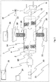
- Fig. 1 shows an ice detection unit 1 according to the present invention.
- Said ice detection unit 1 comprises at least a channeling element 2 for guiding water and for holding ice 4, an excitation means 6 for exciting said channeling element 2 and an excitation detection means 8 for detecting excitations of the channeling element 2, wherein a mechanical connection between the channeling element 2 and at least the excitation means 6 and/or the excitation detection means 8 establishes due to a solidification of fluid, in particular water, inside the channeling element 2, wherein the mechanical connection transfers excitations from the excitation means 2 to the excitation detection means 8.
- Excitation means 6 preferably comprises an excitation part 10, in particular a pivotable longitudinal element.
- the excitation detection means 8 preferably comprises an excitation detection part 12, which is preferably a longitudinal, in particular flat, element that extends into channeling element 2.
- Reference number 16 indicates a holding means.
- Said holding means 16 comprises a first spring 18 and a second spring 20, wherein the first spring 16 is preferably coupled with the top side of channeling element 2 and wherein the second spring 18 is preferably coupled with the bottom side of channeling element 2.
- Both springs 16, 18 are preferably coupled with a wall member 22, in particular of a refrigerator 25 (cf. Fig. 2 ).
- Holding means 16 allows a defined positioning and excitation of channeling element 2.
- Reference number 30 indicates an operation scheme for operating excitation means 6.
- Said operation scheme can be provided as data.
- Said operation scheme is preferably provided and executed respectively processed by control unit 24. Therefore, control unit 24 is preferably connected for signal and/or data exchange with excitation means 6 and/or excitation detection means 8.
- Excitation detection means 8 preferably directly actuates a further means, in particular heater means 26 (cf. fig. 2 ). It is also conceivable that excitation detection means 8 provides data and/or signals representative for detected excitation respectively vibration. Said data and/or signals can be processed or evaluated by control unit 24 and can be used for actuating said further means, in particular heater means 26 (cf. fig. 1 ).
- the working principle is based on excitation and sensing.
- heat-exchanger respectively cooling means 26 starts cooling and icing.
- the vibration motor respectively excitation means 6 is excited by certain time intervals with excitation of ice control signal when heat-exchanger 26 starts cooling.
- the excitations of vibration motor 6 cannot create any vibration on the solid pipe 2 and/or on vibration sensor respectively vibration detection means 8.
- Vibrator leg respectively excitation part 10 of motor 6 cannot hit the solid pipe 2.
- thick layer of ice 4 fills the inside of the solid pipe 2 which preferably has a grid 14 surface.
- ice filled solid pipe 2 starts the vibration transfer from vibration motor 6 side to vibration sensor side respectively excitation detection means 8.
- Vibrator leg 10 of motor 6 hit the ice 4 that occurs inside of pipe 2. So excited vibration reaches the inside surface of pipe 2 with help of good transmission of vibration by solid materials (ice).
- excited vibration reaches perfectly to vibration sensor 8.
- vibration sensor 8 There are different type vibration sensor 8 that returns from vibration to voltage, current or resistance. The resistance, voltage or current of vibration sensor changes with respect to perceived vibration intensity.
- This system can be used both with microcontroller respectively control unit 24 or directly hardware system with no microcontroller. This system is also perfectly isolated. There is highly preferably no electrical conductivity between excitation side and sensor side.
- the invention describes an ice detection unit 1, which at least comprises a channeling element 2 for guiding water and for holding ice 4, an excitation means 6 for exciting said channeling element 2 and an excitation detection means 8 for detecting excitations of the channeling element 2, wherein a mechanical connection between the channeling element 2 and at least the excitation means 6 and/or the excitation detection means 8 establishes due to a solidification of fluid, in particular water, inside the channeling element 2,wherein the mechanical connection transfers excitations from the excitation means 2 to the excitation detection means 8.
Landscapes
- Engineering & Computer Science (AREA)
- Chemical & Material Sciences (AREA)
- Combustion & Propulsion (AREA)
- Physics & Mathematics (AREA)
- Mechanical Engineering (AREA)
- Thermal Sciences (AREA)
- General Engineering & Computer Science (AREA)
- Production, Working, Storing, Or Distribution Of Ice (AREA)
- Defrosting Systems (AREA)
- Investigating Or Analyzing Materials By The Use Of Electric Means (AREA)
Claims (13)
- Unité de détection de glace (1),
comprenant au moins
un élément de canalisation (2) pour guider de l'eau et pour maintenir de la glace (4),
un moyen d'excitation (6) pour exciter ledit élément de canalisation (2) et
un moyen de détection d'excitation (8) pour détecter des excitations de l'élément de canalisation (2),
dans laquelle une connexion mécanique entre l'élément de canalisation (2) et au moins le moyen d'excitation (6) et/ou le moyen de détection d'excitation (8) s'établit en raison d'une solidification du fluide, en particulier de l'eau, à l'intérieur de l'élément de canalisation (2),
dans laquelle la connexion mécanique transfère les excitations du moyen d'excitation (2) au moyen de détection d'excitation (8),
caractérisée par
un moyen de maintien (16) pour le maintien dudit élément de canalisation (2) dans une position prédéfinie,
dans laquelle ledit moyen de maintien (16) comprend au moins un élément à ressort (18) et
dans laquelle l'élément de canalisation (2) comprend au moins une grille (14) ou une surface interne structurée pour permettre à l'eau solidifiée de se développer dans une direction radiale
et
dans laquelle l'élément de canalisation (2) a au moins vers les extrémités axiales et au moins dans des sections une forme tubulaire. - Unité de détection de glace selon la revendication 1,
caractérisée en ce qu'au moins le moyen d'excitation (6) a une partie d'excitation (10) arrivant d'un côté de l'élément de canalisation (2) à l'intérieur d'une section de forme tubulaire sans entrer en contact avec ledit élément de canalisation (2). - Unité de détection de glace selon la revendication 1 ou 2,
caractérisée en ce qu'au moins le moyen de détection d'excitation (8) a une partie de détection d'excitation (12) arrivant de l'autre côté de l'élément de canalisation (2) à l'intérieur d'une section de forme tubulaire sans entrer en contact avec ledit élément de canalisation (2). - Unité de détection de glace selon la revendication 1,
caractérisée en ce que
le moyen de maintien (16) comprend au moins deux éléments à ressort (18, 20), dans laquelle un premier élément à ressort (18) est agencé sur un côté supérieur d'une section de connexion de forme tubulaire de l'élément de canalisation (2) et dans laquelle un second élément à ressort (20) est agencé sur un côté inférieur de ladite section de connexion de forme tubulaire, dans laquelle la section de connexion de forme tubulaire est positionnée entre les extrémités axiales dudit élément de canalisation (2), dans laquelle chacun desdits éléments à ressort (18, 20) a une extrémité supplémentaire devant être couplée à une pièce de paroi (22) environnante, en particulier stationnaire. - Unité de détection de glace selon l'une quelconque des revendications 1 à 4,
caractérisée en ce que
le moyen d'excitation (6) pour exciter ledit élément de canalisation (2) comprend un moteur à vibrations,
dans laquelle ladite partie d'excitation (10) est un pivot rotatif,
dans laquelle ledit pivot rotatif est actionné au moyen d'un actionnement dudit moteur à vibrations,
le moyen de détection d'excitation (12) pour détecter des excitations de l'élément de canalisation (2) est un capteur de vibrations,
dans laquelle la partie de détection d'excitation (12) est connectée audit capteur de vibrations et transfère les vibrations de l'élément de canalisation (2) au capteur de vibrations. - Unité de détection de glace selon l'une quelconque des revendications précédentes,
caractérisée par
une unité de commande (24),
dans laquelle l'unité de commande (24) fait fonctionner le moyen d'excitation (6) en raison de règles prédéfinies,
dans laquelle le moyen de détection d'excitation (8) délivre en sortie des signaux d'excitation en fonction des excitations détectées,
dans laquelle l'unité de commande (24) fournit des signaux de commande en fonction des signaux d'excitation détectés pour le fonctionnement d'au moins un moyen supplémentaire. - Unité de détection de glace selon la revendication 5,
caractérisée en ce que
le moyen de détection d'excitation (8) détecte des changements de valeur de résistance et/ou de tension et/ou de courant,
dans laquelle une première plage de valeurs représente une intensité d'excitation de bas niveau,
dans laquelle aucun signal pour le fonctionnement du moyen supplémentaire n'est fourni par le moyen de commande (24) si une intensité d'excitation de bas niveau est déterminée
dans laquelle une deuxième plage de valeurs représente une intensité d'excitation de niveau moyen,
dans laquelle des signaux pour le fonctionnement du moyen supplémentaire sont fournis par le moyen de commande (24) si une intensité d'excitation de niveau moyen est déterminée,
dans laquelle une troisième plage de valeurs représente une intensité d'excitation de haut niveau,
dans laquelle des signaux pour le fonctionnement du moyen supplémentaire sont fournis par le moyen de commande (24) si une intensité d'excitation de haut niveau est déterminée,
dans laquelle les signaux pour le fonctionnement du moyen supplémentaire entraînent un fonctionnement plus long du moyen supplémentaire dans le cas où une intensité d'excitation de haut niveau est déterminée en comparaison à un cas dans lequel une intensité d'excitation de niveau moyen est déterminée. - Unité de détection de glace selon l'une quelconque des revendications précédentes,
caractérisée en ce que
le moyen d'excitation (6) et le moyen de détection d'excitation (8) sont isolés électriquement l'un de l'autre. - Unité de détection de glace selon l'une quelconque des revendications précédentes,
caractérisée en ce que
le fluide, en particulier l'eau, gèle en dessous de 5°, en particulier en dessous de 1° ou en dessous de 0°, et à une pression ambiante de 10,1 N/cm2. - Réfrigérateur (25), en particulier réfrigérateur sans givre,
comprenant au moins
un moyen de refroidissement (26) pour le refroidissement de l'atmosphère à l'intérieur du réfrigérateur (25),
un moyen de chauffage (28) pour la fusion de la glace ou de la neige accumulée à l'intérieur dudit réfrigérateur (25),
une unité de détection de glace (19) selon l'une quelconque des revendications mentionnées précédemment pour détecter de la glace (4) ou de la neige à l'intérieur du réfrigérateur (25) et pour actionner le moyen de chauffage (28) en fonction de la glace (4) ou de la neige détectée. - Procédé de fonctionnement d'un réfrigérateur (25),
comprenant au moins les étapes :refroidissement d'une section de stockage d'aliments au moyen d'un moyen de refroidissement (26),détection de glace (4) ou de neige à l'intérieur de la section de stockage d'aliments au moyen du fonctionnement d'une unité de détection de glace (1) selon l'une quelconque des revendications 1 à 9,fonctionnement d'un moyen de chauffage (28) dans le cas où la présence de glace (4) ou de neige est détectée. - Procédé selon la revendication 11,
caractérisé en ce que
le moyen de chauffage (28) fonctionne tant qu'un couplage mécanique entre le moyen d'excitation (6) et le moyen de détection d'excitation (8) est présent. - Procédé selon la revendication 11,
caractérisé en ce que
le moyen de chauffage (28) fonctionne pendant une durée prédéterminée,
dans lequel la durée prédéterminée dépend du niveau déterminé de l'intensité d'excitation.
Priority Applications (2)
| Application Number | Priority Date | Filing Date | Title |
|---|---|---|---|
| EP16206196.4A EP3339773B1 (fr) | 2016-12-22 | 2016-12-22 | Unité de détection de glace à base d'excitation, réfrigérateur ayant une unité de détection de glace et procédé de dégivrage d'un réfrigérateur |
| TR2017/02638A TR201702638A2 (tr) | 2016-12-22 | 2017-02-22 | İkaz temelli̇ buz tespi̇t üni̇tesi̇, buz tespi̇t üni̇teli̇ soğutucu ve bi̇r soğutucunun buz çözme yöntemi̇ |
Applications Claiming Priority (1)
| Application Number | Priority Date | Filing Date | Title |
|---|---|---|---|
| EP16206196.4A EP3339773B1 (fr) | 2016-12-22 | 2016-12-22 | Unité de détection de glace à base d'excitation, réfrigérateur ayant une unité de détection de glace et procédé de dégivrage d'un réfrigérateur |
Publications (2)
| Publication Number | Publication Date |
|---|---|
| EP3339773A1 EP3339773A1 (fr) | 2018-06-27 |
| EP3339773B1 true EP3339773B1 (fr) | 2020-02-05 |
Family
ID=57777426
Family Applications (1)
| Application Number | Title | Priority Date | Filing Date |
|---|---|---|---|
| EP16206196.4A Active EP3339773B1 (fr) | 2016-12-22 | 2016-12-22 | Unité de détection de glace à base d'excitation, réfrigérateur ayant une unité de détection de glace et procédé de dégivrage d'un réfrigérateur |
Country Status (2)
| Country | Link |
|---|---|
| EP (1) | EP3339773B1 (fr) |
| TR (1) | TR201702638A2 (fr) |
Family Cites Families (8)
| Publication number | Priority date | Publication date | Assignee | Title |
|---|---|---|---|---|
| US3641781A (en) * | 1970-04-22 | 1972-02-15 | Kiyoichi Nijo | Method of detecting temperature for controlling a refrigerator or a freezer |
| DE2020311A1 (de) * | 1970-04-25 | 1971-11-04 | Kiyoichi Nijo | Verfahren und Vorrichtung zur Temperaturermittlung zwecks Regelung eines Kuehlschranks oder Gefrierers |
| GB1320251A (en) | 1971-05-20 | 1973-06-13 | Findlay Irvine Ltd | Apparatus for providing an indication of the imminence of ice- formation |
| DE2641600A1 (de) | 1976-09-16 | 1978-03-23 | Stiebel Eltron Gmbh & Co Kg | Ausloeseeinrichtung fuer eine abtauvorrichtung |
| CA1090441A (fr) * | 1976-11-10 | 1980-11-25 | Toshibumi Kamiyama | Detecteur de givre |
| US4843830A (en) | 1988-10-11 | 1989-07-04 | Emerson Electric Co. | Differential ice sensor and method |
| AU5398099A (en) | 1998-08-14 | 2000-03-06 | Imi Cornelius Inc. | Ice bank control with voltage protection sensing |
| JP4165792B2 (ja) * | 2000-12-13 | 2008-10-15 | 日世冷機株式会社 | 冷菓製造装置及びその固さ制御方法 |
-
2016
- 2016-12-22 EP EP16206196.4A patent/EP3339773B1/fr active Active
-
2017
- 2017-02-22 TR TR2017/02638A patent/TR201702638A2/tr unknown
Non-Patent Citations (1)
| Title |
|---|
| None * |
Also Published As
| Publication number | Publication date |
|---|---|
| EP3339773A1 (fr) | 2018-06-27 |
| TR201702638A2 (tr) | 2018-07-23 |
Similar Documents
| Publication | Publication Date | Title |
|---|---|---|
| EP2409095B1 (fr) | Arrêt de dégivrage commandé par microprocesseur | |
| US20160370092A1 (en) | Apparatus and method for making ice in refrigeration equipment | |
| JP5078829B2 (ja) | 冷蔵庫 | |
| US20160025403A1 (en) | Temperature regulating system and method of deicing the temperature regulating system | |
| RU2349847C2 (ru) | Холодильный аппарат и способ его эксплуатации | |
| CN208012210U (zh) | 带有自动检测和自动除冰功能的冷凝器系统 | |
| KR102425166B1 (ko) | 액체를 냉각시키기 위한 냉각 배스 | |
| EP3339773B1 (fr) | Unité de détection de glace à base d'excitation, réfrigérateur ayant une unité de détection de glace et procédé de dégivrage d'un réfrigérateur | |
| JP2003314932A (ja) | 冷凍機 | |
| US20160018154A1 (en) | Sensor for coil defrost in a refrigeration system evaporator | |
| CN204085027U (zh) | 冰箱中水管路结构及冰箱 | |
| EP3339774A1 (fr) | Unité de détection de glace à base de lumière, unité de détection de glace pour réfrigérateur et procédé de dégivrage d'un réfrigérateur | |
| JP2004251480A (ja) | 冷凍装置 | |
| JP2000074546A (ja) | 冷凍機の除霜制御装置 | |
| EP3355009A1 (fr) | Unité de détection de glace et réfrigérateur comportant une telle unité de détection de glace utilisant les propriétés hydrodynamiques de liquides et procédé de dégivrage d'un réfrigérateur | |
| JP2016223669A (ja) | 制御装置及びヒートポンプ式給湯装置 | |
| JP6847262B2 (ja) | 冷蔵庫、ヒータ駆動装置、ヒータ駆動方法およびプログラム | |
| EP3977029B1 (fr) | Dispositif pour détecter la formation de glace d'eau | |
| KR20160020101A (ko) | 제빙기 및 이를 포함하는 냉장고 | |
| GB2523686A (en) | Refrigerator having a refrigeration compartment | |
| EP3401624A1 (fr) | Unité de climatisation ayant une fonction de détection de neige et de glace à base de courant et procédé de fonctionnement d'une telle unité de climatisation | |
| KR100288263B1 (ko) | 냉장고의제상장치 | |
| CN103851857A (zh) | 冰箱中水管路结构及冰箱 | |
| JPH1151531A (ja) | 製氷検知器 | |
| TR201908262A2 (tr) | Su buzu oluşumunu tespi̇t etmeye yöneli̇k ci̇haz |
Legal Events
| Date | Code | Title | Description |
|---|---|---|---|
| PUAI | Public reference made under article 153(3) epc to a published international application that has entered the european phase |
Free format text: ORIGINAL CODE: 0009012 |
|
| STAA | Information on the status of an ep patent application or granted ep patent |
Free format text: STATUS: THE APPLICATION HAS BEEN PUBLISHED |
|
| AK | Designated contracting states |
Kind code of ref document: A1 Designated state(s): AL AT BE BG CH CY CZ DE DK EE ES FI FR GB GR HR HU IE IS IT LI LT LU LV MC MK MT NL NO PL PT RO RS SE SI SK SM TR |
|
| AX | Request for extension of the european patent |
Extension state: BA ME |
|
| STAA | Information on the status of an ep patent application or granted ep patent |
Free format text: STATUS: REQUEST FOR EXAMINATION WAS MADE |
|
| 17P | Request for examination filed |
Effective date: 20190102 |
|
| RBV | Designated contracting states (corrected) |
Designated state(s): AL AT BE BG CH CY CZ DE DK EE ES FI FR GB GR HR HU IE IS IT LI LT LU LV MC MK MT NL NO PL PT RO RS SE SI SK SM TR |
|
| GRAP | Despatch of communication of intention to grant a patent |
Free format text: ORIGINAL CODE: EPIDOSNIGR1 |
|
| STAA | Information on the status of an ep patent application or granted ep patent |
Free format text: STATUS: GRANT OF PATENT IS INTENDED |
|
| RIC1 | Information provided on ipc code assigned before grant |
Ipc: F25D 21/02 20060101AFI20190218BHEP |
|
| INTG | Intention to grant announced |
Effective date: 20190313 |
|
| GRAS | Grant fee paid |
Free format text: ORIGINAL CODE: EPIDOSNIGR3 |
|
| GRAJ | Information related to disapproval of communication of intention to grant by the applicant or resumption of examination proceedings by the epo deleted |
Free format text: ORIGINAL CODE: EPIDOSDIGR1 |
|
| GRAL | Information related to payment of fee for publishing/printing deleted |
Free format text: ORIGINAL CODE: EPIDOSDIGR3 |
|
| STAA | Information on the status of an ep patent application or granted ep patent |
Free format text: STATUS: REQUEST FOR EXAMINATION WAS MADE |
|
| GRAP | Despatch of communication of intention to grant a patent |
Free format text: ORIGINAL CODE: EPIDOSNIGR1 |
|
| STAA | Information on the status of an ep patent application or granted ep patent |
Free format text: STATUS: GRANT OF PATENT IS INTENDED |
|
| INTC | Intention to grant announced (deleted) | ||
| INTG | Intention to grant announced |
Effective date: 20190729 |
|
| GRAA | (expected) grant |
Free format text: ORIGINAL CODE: 0009210 |
|
| STAA | Information on the status of an ep patent application or granted ep patent |
Free format text: STATUS: THE PATENT HAS BEEN GRANTED |
|
| AK | Designated contracting states |
Kind code of ref document: B1 Designated state(s): AL AT BE BG CH CY CZ DE DK EE ES FI FR GB GR HR HU IE IS IT LI LT LU LV MC MK MT NL NO PL PT RO RS SE SI SK SM TR |
|
| REG | Reference to a national code |
Ref country code: GB Ref legal event code: FG4D |
|
| REG | Reference to a national code |
Ref country code: AT Ref legal event code: REF Ref document number: 1230204 Country of ref document: AT Kind code of ref document: T Effective date: 20200215 |
|
| REG | Reference to a national code |
Ref country code: DE Ref legal event code: R096 Ref document number: 602016029072 Country of ref document: DE |
|
| REG | Reference to a national code |
Ref country code: IE Ref legal event code: FG4D |
|
| REG | Reference to a national code |
Ref country code: CH Ref legal event code: EP |
|
| REG | Reference to a national code |
Ref country code: NL Ref legal event code: MP Effective date: 20200205 |
|
| PG25 | Lapsed in a contracting state [announced via postgrant information from national office to epo] |
Ref country code: FI Free format text: LAPSE BECAUSE OF FAILURE TO SUBMIT A TRANSLATION OF THE DESCRIPTION OR TO PAY THE FEE WITHIN THE PRESCRIBED TIME-LIMIT Effective date: 20200205 Ref country code: PT Free format text: LAPSE BECAUSE OF FAILURE TO SUBMIT A TRANSLATION OF THE DESCRIPTION OR TO PAY THE FEE WITHIN THE PRESCRIBED TIME-LIMIT Effective date: 20200628 Ref country code: NO Free format text: LAPSE BECAUSE OF FAILURE TO SUBMIT A TRANSLATION OF THE DESCRIPTION OR TO PAY THE FEE WITHIN THE PRESCRIBED TIME-LIMIT Effective date: 20200505 Ref country code: RS Free format text: LAPSE BECAUSE OF FAILURE TO SUBMIT A TRANSLATION OF THE DESCRIPTION OR TO PAY THE FEE WITHIN THE PRESCRIBED TIME-LIMIT Effective date: 20200205 |
|
| REG | Reference to a national code |
Ref country code: LT Ref legal event code: MG4D |
|
| PG25 | Lapsed in a contracting state [announced via postgrant information from national office to epo] |
Ref country code: BG Free format text: LAPSE BECAUSE OF FAILURE TO SUBMIT A TRANSLATION OF THE DESCRIPTION OR TO PAY THE FEE WITHIN THE PRESCRIBED TIME-LIMIT Effective date: 20200505 Ref country code: GR Free format text: LAPSE BECAUSE OF FAILURE TO SUBMIT A TRANSLATION OF THE DESCRIPTION OR TO PAY THE FEE WITHIN THE PRESCRIBED TIME-LIMIT Effective date: 20200506 Ref country code: LV Free format text: LAPSE BECAUSE OF FAILURE TO SUBMIT A TRANSLATION OF THE DESCRIPTION OR TO PAY THE FEE WITHIN THE PRESCRIBED TIME-LIMIT Effective date: 20200205 Ref country code: IS Free format text: LAPSE BECAUSE OF FAILURE TO SUBMIT A TRANSLATION OF THE DESCRIPTION OR TO PAY THE FEE WITHIN THE PRESCRIBED TIME-LIMIT Effective date: 20200605 Ref country code: SE Free format text: LAPSE BECAUSE OF FAILURE TO SUBMIT A TRANSLATION OF THE DESCRIPTION OR TO PAY THE FEE WITHIN THE PRESCRIBED TIME-LIMIT Effective date: 20200205 Ref country code: HR Free format text: LAPSE BECAUSE OF FAILURE TO SUBMIT A TRANSLATION OF THE DESCRIPTION OR TO PAY THE FEE WITHIN THE PRESCRIBED TIME-LIMIT Effective date: 20200205 |
|
| PG25 | Lapsed in a contracting state [announced via postgrant information from national office to epo] |
Ref country code: NL Free format text: LAPSE BECAUSE OF FAILURE TO SUBMIT A TRANSLATION OF THE DESCRIPTION OR TO PAY THE FEE WITHIN THE PRESCRIBED TIME-LIMIT Effective date: 20200205 |
|
| PG25 | Lapsed in a contracting state [announced via postgrant information from national office to epo] |
Ref country code: SM Free format text: LAPSE BECAUSE OF FAILURE TO SUBMIT A TRANSLATION OF THE DESCRIPTION OR TO PAY THE FEE WITHIN THE PRESCRIBED TIME-LIMIT Effective date: 20200205 Ref country code: EE Free format text: LAPSE BECAUSE OF FAILURE TO SUBMIT A TRANSLATION OF THE DESCRIPTION OR TO PAY THE FEE WITHIN THE PRESCRIBED TIME-LIMIT Effective date: 20200205 Ref country code: DK Free format text: LAPSE BECAUSE OF FAILURE TO SUBMIT A TRANSLATION OF THE DESCRIPTION OR TO PAY THE FEE WITHIN THE PRESCRIBED TIME-LIMIT Effective date: 20200205 Ref country code: ES Free format text: LAPSE BECAUSE OF FAILURE TO SUBMIT A TRANSLATION OF THE DESCRIPTION OR TO PAY THE FEE WITHIN THE PRESCRIBED TIME-LIMIT Effective date: 20200205 Ref country code: LT Free format text: LAPSE BECAUSE OF FAILURE TO SUBMIT A TRANSLATION OF THE DESCRIPTION OR TO PAY THE FEE WITHIN THE PRESCRIBED TIME-LIMIT Effective date: 20200205 Ref country code: CZ Free format text: LAPSE BECAUSE OF FAILURE TO SUBMIT A TRANSLATION OF THE DESCRIPTION OR TO PAY THE FEE WITHIN THE PRESCRIBED TIME-LIMIT Effective date: 20200205 Ref country code: RO Free format text: LAPSE BECAUSE OF FAILURE TO SUBMIT A TRANSLATION OF THE DESCRIPTION OR TO PAY THE FEE WITHIN THE PRESCRIBED TIME-LIMIT Effective date: 20200205 Ref country code: SK Free format text: LAPSE BECAUSE OF FAILURE TO SUBMIT A TRANSLATION OF THE DESCRIPTION OR TO PAY THE FEE WITHIN THE PRESCRIBED TIME-LIMIT Effective date: 20200205 |
|
| REG | Reference to a national code |
Ref country code: DE Ref legal event code: R097 Ref document number: 602016029072 Country of ref document: DE |
|
| REG | Reference to a national code |
Ref country code: AT Ref legal event code: MK05 Ref document number: 1230204 Country of ref document: AT Kind code of ref document: T Effective date: 20200205 |
|
| PLBE | No opposition filed within time limit |
Free format text: ORIGINAL CODE: 0009261 |
|
| STAA | Information on the status of an ep patent application or granted ep patent |
Free format text: STATUS: NO OPPOSITION FILED WITHIN TIME LIMIT |
|
| 26N | No opposition filed |
Effective date: 20201106 |
|
| PG25 | Lapsed in a contracting state [announced via postgrant information from national office to epo] |
Ref country code: AT Free format text: LAPSE BECAUSE OF FAILURE TO SUBMIT A TRANSLATION OF THE DESCRIPTION OR TO PAY THE FEE WITHIN THE PRESCRIBED TIME-LIMIT Effective date: 20200205 Ref country code: IT Free format text: LAPSE BECAUSE OF FAILURE TO SUBMIT A TRANSLATION OF THE DESCRIPTION OR TO PAY THE FEE WITHIN THE PRESCRIBED TIME-LIMIT Effective date: 20200205 |
|
| PG25 | Lapsed in a contracting state [announced via postgrant information from national office to epo] |
Ref country code: PL Free format text: LAPSE BECAUSE OF FAILURE TO SUBMIT A TRANSLATION OF THE DESCRIPTION OR TO PAY THE FEE WITHIN THE PRESCRIBED TIME-LIMIT Effective date: 20200205 Ref country code: SI Free format text: LAPSE BECAUSE OF FAILURE TO SUBMIT A TRANSLATION OF THE DESCRIPTION OR TO PAY THE FEE WITHIN THE PRESCRIBED TIME-LIMIT Effective date: 20200205 |
|
| REG | Reference to a national code |
Ref country code: CH Ref legal event code: PL |
|
| PG25 | Lapsed in a contracting state [announced via postgrant information from national office to epo] |
Ref country code: MC Free format text: LAPSE BECAUSE OF FAILURE TO SUBMIT A TRANSLATION OF THE DESCRIPTION OR TO PAY THE FEE WITHIN THE PRESCRIBED TIME-LIMIT Effective date: 20200205 |
|
| REG | Reference to a national code |
Ref country code: BE Ref legal event code: MM Effective date: 20201231 |
|
| PG25 | Lapsed in a contracting state [announced via postgrant information from national office to epo] |
Ref country code: FR Free format text: LAPSE BECAUSE OF NON-PAYMENT OF DUE FEES Effective date: 20201231 Ref country code: LU Free format text: LAPSE BECAUSE OF NON-PAYMENT OF DUE FEES Effective date: 20201222 Ref country code: IE Free format text: LAPSE BECAUSE OF NON-PAYMENT OF DUE FEES Effective date: 20201222 |
|
| PG25 | Lapsed in a contracting state [announced via postgrant information from national office to epo] |
Ref country code: CH Free format text: LAPSE BECAUSE OF NON-PAYMENT OF DUE FEES Effective date: 20201231 Ref country code: LI Free format text: LAPSE BECAUSE OF NON-PAYMENT OF DUE FEES Effective date: 20201231 |
|
| PG25 | Lapsed in a contracting state [announced via postgrant information from national office to epo] |
Ref country code: MT Free format text: LAPSE BECAUSE OF FAILURE TO SUBMIT A TRANSLATION OF THE DESCRIPTION OR TO PAY THE FEE WITHIN THE PRESCRIBED TIME-LIMIT Effective date: 20200205 Ref country code: CY Free format text: LAPSE BECAUSE OF FAILURE TO SUBMIT A TRANSLATION OF THE DESCRIPTION OR TO PAY THE FEE WITHIN THE PRESCRIBED TIME-LIMIT Effective date: 20200205 |
|
| PG25 | Lapsed in a contracting state [announced via postgrant information from national office to epo] |
Ref country code: MK Free format text: LAPSE BECAUSE OF FAILURE TO SUBMIT A TRANSLATION OF THE DESCRIPTION OR TO PAY THE FEE WITHIN THE PRESCRIBED TIME-LIMIT Effective date: 20200205 Ref country code: AL Free format text: LAPSE BECAUSE OF FAILURE TO SUBMIT A TRANSLATION OF THE DESCRIPTION OR TO PAY THE FEE WITHIN THE PRESCRIBED TIME-LIMIT Effective date: 20200205 |
|
| PG25 | Lapsed in a contracting state [announced via postgrant information from national office to epo] |
Ref country code: BE Free format text: LAPSE BECAUSE OF NON-PAYMENT OF DUE FEES Effective date: 20201231 |
|
| PGFP | Annual fee paid to national office [announced via postgrant information from national office to epo] |
Ref country code: GB Payment date: 20231220 Year of fee payment: 8 |
|
| PGFP | Annual fee paid to national office [announced via postgrant information from national office to epo] |
Ref country code: DE Payment date: 20231214 Year of fee payment: 8 |
|
| REG | Reference to a national code |
Ref country code: DE Ref legal event code: R119 Ref document number: 602016029072 Country of ref document: DE |
|
| GBPC | Gb: european patent ceased through non-payment of renewal fee |
Effective date: 20241222 |
|
| PG25 | Lapsed in a contracting state [announced via postgrant information from national office to epo] |
Ref country code: DE Free format text: LAPSE BECAUSE OF NON-PAYMENT OF DUE FEES Effective date: 20250701 |
|
| PG25 | Lapsed in a contracting state [announced via postgrant information from national office to epo] |
Ref country code: GB Free format text: LAPSE BECAUSE OF NON-PAYMENT OF DUE FEES Effective date: 20241222 |
|
| PGFP | Annual fee paid to national office [announced via postgrant information from national office to epo] |
Ref country code: TR Payment date: 20251217 Year of fee payment: 10 |