EP3339794A2 - Évaporateur de milieux poreux - Google Patents
Évaporateur de milieux poreux Download PDFInfo
- Publication number
- EP3339794A2 EP3339794A2 EP17206833.0A EP17206833A EP3339794A2 EP 3339794 A2 EP3339794 A2 EP 3339794A2 EP 17206833 A EP17206833 A EP 17206833A EP 3339794 A2 EP3339794 A2 EP 3339794A2
- Authority
- EP
- European Patent Office
- Prior art keywords
- porous
- evaporator
- vapor
- interface
- outlet interface
- Prior art date
- Legal status (The legal status is an assumption and is not a legal conclusion. Google has not performed a legal analysis and makes no representation as to the accuracy of the status listed.)
- Granted
Links
Images


Classifications
-
- F—MECHANICAL ENGINEERING; LIGHTING; HEATING; WEAPONS; BLASTING
- F28—HEAT EXCHANGE IN GENERAL
- F28F—DETAILS OF HEAT-EXCHANGE AND HEAT-TRANSFER APPARATUS, OF GENERAL APPLICATION
- F28F13/00—Arrangements for modifying heat-transfer, e.g. increasing, decreasing
- F28F13/003—Arrangements for modifying heat-transfer, e.g. increasing, decreasing by using permeable mass, perforated or porous materials
-
- F—MECHANICAL ENGINEERING; LIGHTING; HEATING; WEAPONS; BLASTING
- F25—REFRIGERATION OR COOLING; COMBINED HEATING AND REFRIGERATION SYSTEMS; HEAT PUMP SYSTEMS; MANUFACTURE OR STORAGE OF ICE; LIQUEFACTION SOLIDIFICATION OF GASES
- F25B—REFRIGERATION MACHINES, PLANTS OR SYSTEMS; COMBINED HEATING AND REFRIGERATION SYSTEMS; HEAT PUMP SYSTEMS
- F25B39/00—Evaporators; Condensers
- F25B39/02—Evaporators
-
- F—MECHANICAL ENGINEERING; LIGHTING; HEATING; WEAPONS; BLASTING
- F28—HEAT EXCHANGE IN GENERAL
- F28D—HEAT-EXCHANGE APPARATUS, NOT PROVIDED FOR IN ANOTHER SUBCLASS, IN WHICH THE HEAT-EXCHANGE MEDIA DO NOT COME INTO DIRECT CONTACT
- F28D15/00—Heat-exchange apparatus with the intermediate heat-transfer medium in closed tubes passing into or through the conduit walls ; Heat-exchange apparatus employing intermediate heat-transfer medium or bodies
- F28D15/02—Heat-exchange apparatus with the intermediate heat-transfer medium in closed tubes passing into or through the conduit walls ; Heat-exchange apparatus employing intermediate heat-transfer medium or bodies in which the medium condenses and evaporates, e.g. heat pipes
- F28D15/04—Heat-exchange apparatus with the intermediate heat-transfer medium in closed tubes passing into or through the conduit walls ; Heat-exchange apparatus employing intermediate heat-transfer medium or bodies in which the medium condenses and evaporates, e.g. heat pipes with tubes having a capillary structure
- F28D15/046—Heat-exchange apparatus with the intermediate heat-transfer medium in closed tubes passing into or through the conduit walls ; Heat-exchange apparatus employing intermediate heat-transfer medium or bodies in which the medium condenses and evaporates, e.g. heat pipes with tubes having a capillary structure characterised by the material or the construction of the capillary structure
-
- F—MECHANICAL ENGINEERING; LIGHTING; HEATING; WEAPONS; BLASTING
- F28—HEAT EXCHANGE IN GENERAL
- F28D—HEAT-EXCHANGE APPARATUS, NOT PROVIDED FOR IN ANOTHER SUBCLASS, IN WHICH THE HEAT-EXCHANGE MEDIA DO NOT COME INTO DIRECT CONTACT
- F28D7/00—Heat-exchange apparatus having stationary tubular conduit assemblies for both heat-exchange media, the media being in contact with different sides of a conduit wall
- F28D7/10—Heat-exchange apparatus having stationary tubular conduit assemblies for both heat-exchange media, the media being in contact with different sides of a conduit wall the conduits being arranged one within the other, e.g. concentrically
- F28D7/106—Heat-exchange apparatus having stationary tubular conduit assemblies for both heat-exchange media, the media being in contact with different sides of a conduit wall the conduits being arranged one within the other, e.g. concentrically consisting of two coaxial conduits or modules of two coaxial conduits
-
- F—MECHANICAL ENGINEERING; LIGHTING; HEATING; WEAPONS; BLASTING
- F25—REFRIGERATION OR COOLING; COMBINED HEATING AND REFRIGERATION SYSTEMS; HEAT PUMP SYSTEMS; MANUFACTURE OR STORAGE OF ICE; LIQUEFACTION SOLIDIFICATION OF GASES
- F25B—REFRIGERATION MACHINES, PLANTS OR SYSTEMS; COMBINED HEATING AND REFRIGERATION SYSTEMS; HEAT PUMP SYSTEMS
- F25B23/00—Machines, plants or systems, with a single mode of operation not covered by groups F25B1/00 - F25B21/00, e.g. using selective radiation effect
- F25B23/006—Machines, plants or systems, with a single mode of operation not covered by groups F25B1/00 - F25B21/00, e.g. using selective radiation effect boiling cooling systems
-
- F—MECHANICAL ENGINEERING; LIGHTING; HEATING; WEAPONS; BLASTING
- F25—REFRIGERATION OR COOLING; COMBINED HEATING AND REFRIGERATION SYSTEMS; HEAT PUMP SYSTEMS; MANUFACTURE OR STORAGE OF ICE; LIQUEFACTION SOLIDIFICATION OF GASES
- F25B—REFRIGERATION MACHINES, PLANTS OR SYSTEMS; COMBINED HEATING AND REFRIGERATION SYSTEMS; HEAT PUMP SYSTEMS
- F25B43/00—Arrangements for separating or purifying gases or liquids; Arrangements for vaporising the residuum of liquid refrigerant, e.g. by heat
-
- F—MECHANICAL ENGINEERING; LIGHTING; HEATING; WEAPONS; BLASTING
- F28—HEAT EXCHANGE IN GENERAL
- F28D—HEAT-EXCHANGE APPARATUS, NOT PROVIDED FOR IN ANOTHER SUBCLASS, IN WHICH THE HEAT-EXCHANGE MEDIA DO NOT COME INTO DIRECT CONTACT
- F28D21/00—Heat-exchange apparatus not covered by any of the groups F28D1/00 - F28D20/00
- F28D2021/0019—Other heat exchangers for particular applications; Heat exchange systems not otherwise provided for
- F28D2021/0061—Other heat exchangers for particular applications; Heat exchange systems not otherwise provided for for phase-change applications
- F28D2021/0064—Vaporizers, e.g. evaporators
-
- F—MECHANICAL ENGINEERING; LIGHTING; HEATING; WEAPONS; BLASTING
- F28—HEAT EXCHANGE IN GENERAL
- F28D—HEAT-EXCHANGE APPARATUS, NOT PROVIDED FOR IN ANOTHER SUBCLASS, IN WHICH THE HEAT-EXCHANGE MEDIA DO NOT COME INTO DIRECT CONTACT
- F28D21/00—Heat-exchange apparatus not covered by any of the groups F28D1/00 - F28D20/00
- F28D2021/0019—Other heat exchangers for particular applications; Heat exchange systems not otherwise provided for
- F28D2021/0068—Other heat exchangers for particular applications; Heat exchange systems not otherwise provided for for refrigerant cycles
- F28D2021/0071—Evaporators
-
- F—MECHANICAL ENGINEERING; LIGHTING; HEATING; WEAPONS; BLASTING
- F28—HEAT EXCHANGE IN GENERAL
- F28D—HEAT-EXCHANGE APPARATUS, NOT PROVIDED FOR IN ANOTHER SUBCLASS, IN WHICH THE HEAT-EXCHANGE MEDIA DO NOT COME INTO DIRECT CONTACT
- F28D21/00—Heat-exchange apparatus not covered by any of the groups F28D1/00 - F28D20/00
- F28D2021/0019—Other heat exchangers for particular applications; Heat exchange systems not otherwise provided for
- F28D2021/008—Other heat exchangers for particular applications; Heat exchange systems not otherwise provided for for vehicles
- F28D2021/0085—Evaporators
Definitions
- the present disclosure relates to heat exchangers and, more specifically, to evaporator components of heat exchangers.
- Heat exchangers are used in a variety of applications.
- Single phase liquid heat exchangers for example, are often used to cool and/or heat components of a system.
- a liquid is pumped across a component and sensible heat is transferred between the liquid and the component and thus the liquid changes temperature.
- These heat exchangers rely on the sensible heat capacity of the liquid to transfer heat.
- these single phase heat exchangers often require large volumes of liquid, which can increase the overall operating costs of a heat exchanger system.
- the present disclosure provides an evaporator that includes a housing having a liquid inlet interface, a liquid outlet interface, and a vapor outlet interface.
- the evaporator also includes, according to various embodiments, a porous media disposed in the housing and having a porous wall that defines a conduit.
- the conduit defined in the porous media may be in fluidic communication between the liquid inlet interface and the liquid outlet interface of the housing.
- fluidic communication between the conduit defined in the porous media and the vapor outlet interface of the housing may be through the porous wall of the porous media.
- the porous wall includes pores that have an average pore size diameter of between about 1.0 micrometer and about 5.0 micrometers.
- the porous media may be cylindrical and the porous wall may be a porous tube that has a radially outward surface and a radially inward surface facing and bordering the conduit.
- the porous tube includes a porous ceramic material.
- the conduit may extend along a longitudinal centerline axis of the porous tube and the radially outward surface may be in direct contact with an internal surface of the housing.
- the radially outward surface may also include a longitudinally extending vapor vent channel.
- the longitudinally extending vapor vent channel may be one of a plurality of longitudinally extending vapor vent channels that are circumferentially distributed across the radially outward surface of the porous tube.
- the longitudinally extending the vapor vent channel is configured to direct vapor to the vapor outlet interface.
- the radially outward surface of the porous tube includes a plurality of circumferentially extending vapor grooves.
- the porous tube includes a multi-layer mesh material.
- the radially outward surface of the porous tube may be in direct contact with a plurality of radially extending fins of an internal surface of the housing. Vapor may be configured to flow between adjacent fins of the plurality of radially extending fins to the vapor outlet interface.
- the porous tube includes an inlet end coupled to the liquid inlet interface and an outlet end coupled to the liquid outlet interface. The inlet end of the porous tube may overlap at least a portion of the liquid inlet interface and the outlet end of the porous tube may overlap at least a portion of the liquid outlet interface.
- the vapor outlet interface is a first vapor outlet interface disposed adjacent the inlet end of the porous tube and the evaporator includes a second vapor outlet interface disposed adjacent the outlet end of the porous tube.
- the evaporator further includes a heat source interface coupled to the housing, wherein heat is configured to conduct from the heat source interface through the housing to liquid flowing through the conduit.
- the porous media may include a porous tube having a radially inward surface and a radially outward surface.
- the radially inward surface may face and border a conduit that extends along a longitudinal centerline axis of the porous tube and the radially outward surface may include a longitudinally extending vapor vent channel.
- the radially outward surface includes a plurality of circumferentially extending vapor grooves.
- the longitudinally extending vapor vent channel may be one of a plurality of longitudinally extending vapor vent channels.
- the heat exchanger system may include a pump, a heat source interface, and an evaporator.
- the evaporator may include a liquid inlet interface configured to be in liquid receiving communication with the pump, a liquid outlet interface, a porous media having a porous wall and defining a conduit, wherein the conduit is disposed between the liquid inlet interface and the liquid outlet interface and the porous wall is configured to be in heat receiving communication with the heat source interface.
- the evaporator may also include a vapor outlet interface configured to be in vapor receiving communication with the porous wall and a valve downstream from the liquid outlet interface and configured to control back pressure in the evaporator.
- flow of vapor through the vapor outlet interface is configured to be controlled by the valve.
- the evaporator is one of a plurality of evaporators and the valve is configured to control back pressure in the plurality of evaporators.
- a first component that is "axially outward" of a second component means that a first component is positioned at a greater distance in either longitudinal direction away from the longitudinal center of the composite component along its longitudinal axis than the second component.
- a first component that is "axially inward” of a second component means that the first component is positioned closer to the longitudinal center of the composite component along its longitudinal axis than the second component.
- a first component that is "radially outward" of a second component means that the first component is positioned at a greater distance away from the longitudinal centerline axis of the composite component than the second component.
- a first component that is "radially inward” of a second component means that the first component is positioned closer to the longitudinal centerline axis of the composite component than the second component.
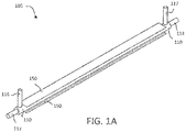
- an evaporator 100 that includes a housing 110 and a porous media 130.
- the housing 110 includes a liquid inlet interface 112, a liquid outlet interface 114, and a vapor outlet interface 116.
- the housing 110 may include multiple vapor outlet interfaces 116, 117.
- the porous media 130 is generally disposed in the housing 110 and includes a porous wall and defines a conduit 134.
- the porous wall as described in greater detail below and according to various embodiments, includes a plurality of pores that extend radially outward from the conduit 134.
- the porous media 130 is generally positioned within the housing 110 so that the conduit 134 is in fluidic communication between the liquid inlet interface 112 and the liquid outlet interface 114.
- fluidic communication between the conduit 134 and the vapor outlet interface 116 is through the porous wall of the porous media 130.
- fluid communication between the conduit 134 and the vapor outlet interface 116 is limited/restricted to the pores of the porous wall.
- liquid is generally pumped into the conduit 134 of the porous media 130 via the liquid inlet interface 112.
- the evaporator 100 may be in heat receiving communication with a heat source.
- the evaporator 100 may include a heat source interface 150 that facilitates the mechanical coupling between and/or promotes the heat transfer between the heat source and the housing 110 of the evaporator 100.
- the porous media 130 is coupled to and/or mounted within the housing 110 so as to also be in heat receiving communication.
- the liquid flowing through conduit 134 may receive latent heat as at least a portion of the liquid undergoes a phase change (e.g., evaporates).
- the resultant vapor flows through the pores of the porous wall and exits the evaporator 100 through the vapor outlet interface 116.
- the liquid inlet interface 112, the liquid outlet interface 114, and the vapor outlet interface 116 are integrally formed and/or are unitary with the housing 110. In various embodiments, the liquid inlet interface 112, the liquid outlet interface 114, and the vapor outlet interface 116 are coupled to or mounted to the housing 110 using various attachment features, such as flange 115.
- the liquid inlet interface 112, the liquid outlet interface 114, and the vapor outlet interface 116 may be portions of tubing that extend between various other components of a heat exchanger system, such as the heat exchanger system 70 described below with reference to FIG. 4 .
- the liquid inlet interface 112, the liquid outlet interface 114, and the vapor outlet interface 116 are connections to which heat exchanger tubing and/or manifolds may be coupled.
- the porous media 130 may have various shapes, geometries, and configurations.
- the porous media 130 is cylindrical and the porous wall is a porous tube 132.
- the conduit 134 may extend along a longitudinal centerline axis of the porous tube 132.
- the porous tube 132 may have an inlet end 136 that is coupled to the liquid inlet interface 112 and the porous tube 132 may have an outlet end 137 that is coupled to the liquid outlet interface 114.
- the vapor outlet interface 116 may be disposed at or adjacent to one of the ends 136, 137 of the porous tube 132. In various embodiments, the vapor outlet interface may be disposed at other locations along the length of the porous tube 132.
- the evaporator 100 may include multiple vapor outlet interfaces 116, 117.
- the evaporator 100 may include a first vapor outlet interface 116 disposed adjacent the inlet end 136 of the porous tube 132 and a second vapor outlet interface 117 disposed adjacent the outlet end 137 of the porous tube 132.
- the housing 110 may be made from various materials, such as metallic materials.
- the housing 110 is constructed from materials that have high heat transfer properties, thereby facilitating the transfer of heat between the heat source (e.g., via the heat source interface 150) and the liquid flowing through the conduit 134.
- the porous media 130 may be made from various materials, such as ceramic materials, metallic materials, composite materials, etc.
- the porous media 130 may be constructed from a monolithic ceramic material that has various radially outward surface features, as described below with reference to FIG. 2 , which facilitate and direct vapor flow.
- the porous media 130 is constructed from a metallic screen mesh or a metallic felt-like material.
- the porous media 130 may include multiple layers.
- the porous media 130 is disposed relative to the housing 110 so that it is in direct physical contact with the housing 110 in order to promote efficient heat transfer (e.g., via conduction) between the housing 110 and the porous media 130.
- the pore size of the porous media 130 is between about 0.1 micrometers and about 20 micrometers. In various embodiments, the pore size of the porous media 130 is between about 0.5 micrometers and about 10 micrometers. In various embodiments, the pore size of the porous media 130 is between about 1 micrometer and about 5 micrometers.
- the size of the pores may be specifically configured for a specific application. For example, the size of the pores, together with the surface tension properties of the liquid, can affect the capillary action of the pores. Additionally, the pressure of the liquid in the conduit 134 and the vapor pressure of the vapor exiting through the vapor outlet interface 116 may affect the steady state operation of the evaporator 100.
- the porous walls of the porous media 230 may have a tube-like geometry.
- the porous media 230 may have a radially inward surface that faces and borders the conduit 234 and a radially outward surface that has various features 231, 233 that facilitate and direct the flow of vapor.
- the radially outward surface of the porous media 230 may be in direct contact with an internal surface of the housing 110.
- the radially outward surface of the porous media 230 may have one or more longitudinally (e.g., axially) extending vapor vent channels 231.
- the longitudinally extending vapor vent channels 231 may be circumferentially distributed (e.g., may be circumferentially spaced apart from each other).
- the radially outward surface of the porous media 230 may include a plurality of circumferentially extending vapor grooves 233 that facilitate flow of the vapor towards the longitudinally extending vapor vent channels 231.
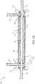
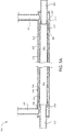
- the evaporator 300 includes an internal surface of the housing 310 that includes a plurality of radially extending fins 319 that contact the radially outward surface of the porous media 330 (described in greater detail below).
- the porous media 330 has a cylindrical shape and thus the porous wall is a porous tube 332 defining a cylindrical conduit 334.
- the inlet end 336 of the porous tube 332 may be coupled to the liquid inlet interface 312 and a first vapor outlet interface 316 may be disposed adjacent the inlet end 336 of the porous tube 332.
- the outlet end 337 of the porous tube 332 may be coupled to the liquid inlet outlet interface 314 and a second vapor outlet interface 317 may be disposed adjacent the outlet end 337 of the porous tube 332.
- the inlet end 336 of the porous tube 332 overlaps at least a portion of the liquid inlet interface 312 and the outlet end 337 of the porous tube 332 overlaps at least a portion of the liquid outlet interface 314.
- FIGS. 3B and 3C illustrate magnified views of the inlet end of the evaporator 300.
- the porous media 330 is not shown in order to provide a clear depiction of the radially extending fins 319 of the internal surface of the housing 310.
- FIG. 3C shows the porous media 330 in its installed/operational position, according to various embodiments. In such embodiments, vapor that passes through the pores of the porous media 330 is directed to flow between adjacent fins of the plurality of radially extending fins 319 towards the one or more vapor outlet interfaces 316, 317.
- a heat exchanger system 70 is provided.
- the heat exchanger system 70 includes a pump 72 that is configured to pump liquid to one or more evaporators 76, 77, which may include the details of the evaporators 100, 300 described above.
- the evaporators 76, 77 may be connected in series or in parallel, and the evaporators 76, 77 may include on or more porous media units 61, 62. 63, which may comprise the details of the porous media 130, 230, 330 described above.
- the vapor that evaporates in the evaporators 76, 77 flows through a condenser heat exchanger, which condenses the vapor back to a liquid and the condensate may be directed to an accumulator for recirculation.
- the liquid that does not evaporate in the evaporators 76, 77 is directed to a heat exchanger where sensible heat is rejected.
- This non-evaporated liquid also flows through a valve 78 that controls the back-pressure of the evaporators 76, 77.
- the valve 78 may be controlled by a controller.
- the non-evaporated liquid may also be directed to an accumulator for recirculation by the pump 72.
- the valve 78 that is downstream of the evaporators 76, 77 in the liquid line may be the exclusive source of control for the back-pressure of the evaporators 76, 77.
- any of the method or process descriptions may be executed in any order and are not necessarily limited to the order presented.
- any reference to singular includes plural embodiments, and any reference to more than one component or step may include a singular embodiment or step.
- Elements and steps in the figures are illustrated for simplicity and clarity and have not necessarily been rendered according to any particular sequence. For example, steps that may be performed concurrently or in different order are illustrated in the figures to help to improve understanding of embodiments of the present disclosure.
- Any reference to attached, fixed, connected or the like may include permanent, removable, temporary, partial, full and/or any other possible attachment option. Additionally, any reference to without contact (or similar phrases) may also include reduced contact or minimal contact. Surface shading lines may be used throughout the figures to denote different parts or areas but not necessarily to denote the same or different materials. In some cases, reference coordinates may be specific to each figure.
- references to "one embodiment”, “an embodiment”, “various embodiments”, etc. indicate that the embodiment described may include a particular feature, structure, or characteristic, but every embodiment may not necessarily include the particular feature, structure, or characteristic. Moreover, such phrases are not necessarily referring to the same embodiment. Further, when a particular feature, structure, or characteristic is described in connection with an embodiment, it is submitted that it is within the knowledge of one skilled in the art to affect such feature, structure, or characteristic in connection with other embodiments whether or not explicitly described. After reading the description, it will be apparent to one skilled in the relevant art(s) how to implement the disclosure in alternative embodiments.
Landscapes
- Engineering & Computer Science (AREA)
- Physics & Mathematics (AREA)
- Thermal Sciences (AREA)
- Mechanical Engineering (AREA)
- General Engineering & Computer Science (AREA)
- Chemical & Material Sciences (AREA)
- Dispersion Chemistry (AREA)
- Life Sciences & Earth Sciences (AREA)
- Sustainable Development (AREA)
- Heat-Exchange Devices With Radiators And Conduit Assemblies (AREA)
- Vaporization, Distillation, Condensation, Sublimation, And Cold Traps (AREA)
Applications Claiming Priority (1)
| Application Number | Priority Date | Filing Date | Title |
|---|---|---|---|
| US15/387,116 US10345052B2 (en) | 2016-12-21 | 2016-12-21 | Porous media evaporator |
Publications (3)
| Publication Number | Publication Date |
|---|---|
| EP3339794A2 true EP3339794A2 (fr) | 2018-06-27 |
| EP3339794A3 EP3339794A3 (fr) | 2018-09-05 |
| EP3339794B1 EP3339794B1 (fr) | 2021-01-27 |
Family
ID=60673308
Family Applications (1)
| Application Number | Title | Priority Date | Filing Date |
|---|---|---|---|
| EP17206833.0A Active EP3339794B1 (fr) | 2016-12-21 | 2017-12-12 | Évaporateur de milieux poreux |
Country Status (2)
| Country | Link |
|---|---|
| US (1) | US10345052B2 (fr) |
| EP (1) | EP3339794B1 (fr) |
Cited By (1)
| Publication number | Priority date | Publication date | Assignee | Title |
|---|---|---|---|---|
| IT201800009390A1 (it) * | 2018-10-12 | 2020-04-12 | Francesco Romanello | Sistema di raffreddamento bifase a convezione forzata |
Families Citing this family (4)
| Publication number | Priority date | Publication date | Assignee | Title |
|---|---|---|---|---|
| CN107278089B (zh) * | 2016-04-07 | 2019-07-19 | 讯凯国际股份有限公司 | 热导结构 |
| US11446585B2 (en) * | 2020-06-08 | 2022-09-20 | Hamilton Sundstrand Corporation | Grooved porous media gas trap for terrestrial and microgravity environment |
| US20230184498A1 (en) * | 2021-12-14 | 2023-06-15 | Amulaire Thermal Technology, Inc. | Immersion-type heat dissipation substrate having microporous structure |
| FR3132932A1 (fr) * | 2022-02-24 | 2023-08-25 | Safran Aircraft Engines | Turbomachine pourvue d’un échangeur thermique hydrogène/air |
Family Cites Families (17)
| Publication number | Priority date | Publication date | Assignee | Title |
|---|---|---|---|---|
| US4470450A (en) * | 1981-10-22 | 1984-09-11 | Lockheed Missiles & Space Co. | Pump-assisted heat pipe |
| DE3526574C1 (de) | 1985-07-25 | 1987-03-26 | Dornier System Gmbh | Kapillarunterstuetzter Verdampfer |
| DE3810128C1 (fr) | 1988-03-25 | 1989-09-07 | Erno Raumfahrttechnik Gmbh, 2800 Bremen, De | |
| US4869313A (en) | 1988-07-15 | 1989-09-26 | General Electric Company | Low pressure drop condenser/evaporator pump heat exchanger |
| JPH0755374A (ja) | 1993-08-18 | 1995-03-03 | Nec Corp | キャピラリポンプループ用蒸発器 |
| FR2723187B1 (fr) | 1994-07-29 | 1996-09-27 | Centre Nat Etd Spatiales | Systeme de transfert d'energie entre une source chaude et une source froide |
| JP2000241089A (ja) * | 1999-02-19 | 2000-09-08 | Mitsubishi Electric Corp | 蒸発器、吸熱器、熱輸送システム及び熱輸送方法 |
| US7931072B1 (en) | 2002-10-02 | 2011-04-26 | Alliant Techsystems Inc. | High heat flux evaporator, heat transfer systems |
| US8136580B2 (en) * | 2000-06-30 | 2012-03-20 | Alliant Techsystems Inc. | Evaporator for a heat transfer system |
| US6672377B2 (en) * | 2002-01-04 | 2004-01-06 | Jui Lung Liu | Oil cooler |
| US7661464B2 (en) | 2005-12-09 | 2010-02-16 | Alliant Techsystems Inc. | Evaporator for use in a heat transfer system |
| US8567486B1 (en) * | 2006-03-22 | 2013-10-29 | Alliant Techsystems Inc. | Reservoir systems including flow directional devices, heat transfer systems including reservoir systems and related methods |
| CN101311662B (zh) | 2007-05-23 | 2011-08-31 | 财团法人工业技术研究院 | 平板式蒸发器散热系统 |
| US8061413B2 (en) * | 2007-09-13 | 2011-11-22 | Battelle Energy Alliance, Llc | Heat exchangers comprising at least one porous member positioned within a casing |
| JP2012132661A (ja) * | 2010-12-01 | 2012-07-12 | Fujitsu Ltd | 冷却装置及び電子装置 |
| DE102011103110B4 (de) | 2011-05-25 | 2014-08-28 | Benteler Automobiltechnik Gmbh | Abgassystem mit Kreislaufwärmerohr |
| US9046288B2 (en) * | 2012-11-21 | 2015-06-02 | Hamilton Sundstrand Space Systems International, Inc. | Pumped two phase fluid routing system and method of routing a working fluid for transferring heat |
-
2016
- 2016-12-21 US US15/387,116 patent/US10345052B2/en active Active
-
2017
- 2017-12-12 EP EP17206833.0A patent/EP3339794B1/fr active Active
Non-Patent Citations (1)
| Title |
|---|
| None |
Cited By (4)
| Publication number | Priority date | Publication date | Assignee | Title |
|---|---|---|---|---|
| IT201800009390A1 (it) * | 2018-10-12 | 2020-04-12 | Francesco Romanello | Sistema di raffreddamento bifase a convezione forzata |
| WO2020075148A1 (fr) * | 2018-10-12 | 2020-04-16 | Francesco Romanello | Système de refroidissement à deux phases à ébullition de flux |
| TWI846739B (zh) * | 2018-10-12 | 2024-07-01 | 法蘭西斯科 羅馬尼洛 | 流動沸騰之兩相冷卻系統 |
| US12117212B2 (en) | 2018-10-12 | 2024-10-15 | Francesco ROMANELLO | Two-phase cooling system with flow boiling |
Also Published As
| Publication number | Publication date |
|---|---|
| US20180172326A1 (en) | 2018-06-21 |
| US10345052B2 (en) | 2019-07-09 |
| EP3339794A3 (fr) | 2018-09-05 |
| EP3339794B1 (fr) | 2021-01-27 |
Similar Documents
| Publication | Publication Date | Title |
|---|---|---|
| EP3339794B1 (fr) | Évaporateur de milieux poreux | |
| US10436521B2 (en) | Dual-mode thermal management loop | |
| US5303768A (en) | Capillary pump evaporator | |
| US10962304B2 (en) | Two-phase thermal loop with rotary separation | |
| CN112179181B (zh) | 螺旋式换热器和换热装置 | |
| EP3392592A1 (fr) | Structure de régulation d'écoulement d'entrée et échangeur de chaleur à plaques | |
| EP3702011B1 (fr) | Boucle thermique biphasée à séparation par membrane | |
| CN112378279B (zh) | 换热器和换热装置 | |
| EP3193127B1 (fr) | Relâchement de la contrainte thermique de echangeurs de chaleur | |
| CN112378280B (zh) | 螺旋型换热器 | |
| EP1971815B1 (fr) | Echangeur thermique a tube multicouche enroule en spirale | |
| US20110209857A1 (en) | Wound Layered Tube Heat Exchanger | |
| CN108253829A (zh) | 微通道阵列辅助驱动的回路热管 | |
| WO2011103574A2 (fr) | Ailettes pour échangeur de chaleur, ensembles et procédés | |
| US20110198063A1 (en) | Tubular heat exchanger, and method of producing a tubular heat exchanger | |
| JP2005147567A (ja) | 2重管式熱交換器 | |
| CN215063907U (zh) | 绕管式换热器及制冷系统 | |
| CN219347468U (zh) | 一种模块化组装的平板环路热管蒸发器 | |
| JP2009068764A (ja) | 2重管式熱交換器 | |
| US20250230995A1 (en) | Fluid distributor for a heat exchanger | |
| EP4479699B1 (fr) | Ensemble évaporateur modulaire pour système de régulation thermique à tube caloporteur en boucle | |
| CN222480641U (zh) | 一种具有单向分流功能的分流器、换热器及空调 | |
| CN103712376A (zh) | 集成有节流装置的换热器和具有它的制冷系统 | |
| CN119245402A (zh) | 一种用空间结构控制流体流动的毛细芯及平板式蒸发器 | |
| JP2005147569A (ja) | 2重管式熱交換器 |
Legal Events
| Date | Code | Title | Description |
|---|---|---|---|
| PUAI | Public reference made under article 153(3) epc to a published international application that has entered the european phase |
Free format text: ORIGINAL CODE: 0009012 |
|
| STAA | Information on the status of an ep patent application or granted ep patent |
Free format text: STATUS: THE APPLICATION HAS BEEN PUBLISHED |
|
| AK | Designated contracting states |
Kind code of ref document: A2 Designated state(s): AL AT BE BG CH CY CZ DE DK EE ES FI FR GB GR HR HU IE IS IT LI LT LU LV MC MK MT NL NO PL PT RO RS SE SI SK SM TR |
|
| AX | Request for extension of the european patent |
Extension state: BA ME |
|
| PUAL | Search report despatched |
Free format text: ORIGINAL CODE: 0009013 |
|
| AK | Designated contracting states |
Kind code of ref document: A3 Designated state(s): AL AT BE BG CH CY CZ DE DK EE ES FI FR GB GR HR HU IE IS IT LI LT LU LV MC MK MT NL NO PL PT RO RS SE SI SK SM TR |
|
| AX | Request for extension of the european patent |
Extension state: BA ME |
|
| RIC1 | Information provided on ipc code assigned before grant |
Ipc: F25B 39/02 20060101ALI20180801BHEP Ipc: F28D 7/10 20060101ALI20180801BHEP Ipc: F28F 13/00 20060101AFI20180801BHEP Ipc: F28D 15/04 20060101ALI20180801BHEP |
|
| STAA | Information on the status of an ep patent application or granted ep patent |
Free format text: STATUS: REQUEST FOR EXAMINATION WAS MADE |
|
| STAA | Information on the status of an ep patent application or granted ep patent |
Free format text: STATUS: EXAMINATION IS IN PROGRESS |
|
| 17P | Request for examination filed |
Effective date: 20190304 |
|
| RBV | Designated contracting states (corrected) |
Designated state(s): AL AT BE BG CH CY CZ DE DK EE ES FI FR GB GR HR HU IE IS IT LI LT LU LV MC MK MT NL NO PL PT RO RS SE SI SK SM TR |
|
| 17Q | First examination report despatched |
Effective date: 20190404 |
|
| GRAP | Despatch of communication of intention to grant a patent |
Free format text: ORIGINAL CODE: EPIDOSNIGR1 |
|
| STAA | Information on the status of an ep patent application or granted ep patent |
Free format text: STATUS: GRANT OF PATENT IS INTENDED |
|
| INTG | Intention to grant announced |
Effective date: 20200713 |
|
| GRAS | Grant fee paid |
Free format text: ORIGINAL CODE: EPIDOSNIGR3 |
|
| GRAA | (expected) grant |
Free format text: ORIGINAL CODE: 0009210 |
|
| STAA | Information on the status of an ep patent application or granted ep patent |
Free format text: STATUS: THE PATENT HAS BEEN GRANTED |
|
| AK | Designated contracting states |
Kind code of ref document: B1 Designated state(s): AL AT BE BG CH CY CZ DE DK EE ES FI FR GB GR HR HU IE IS IT LI LT LU LV MC MK MT NL NO PL PT RO RS SE SI SK SM TR |
|
| REG | Reference to a national code |
Ref country code: GB Ref legal event code: FG4D |
|
| REG | Reference to a national code |
Ref country code: CH Ref legal event code: EP |
|
| REG | Reference to a national code |
Ref country code: AT Ref legal event code: REF Ref document number: 1358747 Country of ref document: AT Kind code of ref document: T Effective date: 20210215 |
|
| REG | Reference to a national code |
Ref country code: IE Ref legal event code: FG4D |
|
| REG | Reference to a national code |
Ref country code: DE Ref legal event code: R096 Ref document number: 602017032001 Country of ref document: DE |
|
| REG | Reference to a national code |
Ref country code: NL Ref legal event code: MP Effective date: 20210127 |
|
| REG | Reference to a national code |
Ref country code: LT Ref legal event code: MG9D |
|
| REG | Reference to a national code |
Ref country code: AT Ref legal event code: MK05 Ref document number: 1358747 Country of ref document: AT Kind code of ref document: T Effective date: 20210127 |
|
| PG25 | Lapsed in a contracting state [announced via postgrant information from national office to epo] |
Ref country code: NO Free format text: LAPSE BECAUSE OF FAILURE TO SUBMIT A TRANSLATION OF THE DESCRIPTION OR TO PAY THE FEE WITHIN THE PRESCRIBED TIME-LIMIT Effective date: 20210427 Ref country code: PT Free format text: LAPSE BECAUSE OF FAILURE TO SUBMIT A TRANSLATION OF THE DESCRIPTION OR TO PAY THE FEE WITHIN THE PRESCRIBED TIME-LIMIT Effective date: 20210527 Ref country code: GR Free format text: LAPSE BECAUSE OF FAILURE TO SUBMIT A TRANSLATION OF THE DESCRIPTION OR TO PAY THE FEE WITHIN THE PRESCRIBED TIME-LIMIT Effective date: 20210428 Ref country code: HR Free format text: LAPSE BECAUSE OF FAILURE TO SUBMIT A TRANSLATION OF THE DESCRIPTION OR TO PAY THE FEE WITHIN THE PRESCRIBED TIME-LIMIT Effective date: 20210127 Ref country code: FI Free format text: LAPSE BECAUSE OF FAILURE TO SUBMIT A TRANSLATION OF THE DESCRIPTION OR TO PAY THE FEE WITHIN THE PRESCRIBED TIME-LIMIT Effective date: 20210127 Ref country code: BG Free format text: LAPSE BECAUSE OF FAILURE TO SUBMIT A TRANSLATION OF THE DESCRIPTION OR TO PAY THE FEE WITHIN THE PRESCRIBED TIME-LIMIT Effective date: 20210427 Ref country code: LT Free format text: LAPSE BECAUSE OF FAILURE TO SUBMIT A TRANSLATION OF THE DESCRIPTION OR TO PAY THE FEE WITHIN THE PRESCRIBED TIME-LIMIT Effective date: 20210127 |
|
| PG25 | Lapsed in a contracting state [announced via postgrant information from national office to epo] |
Ref country code: SE Free format text: LAPSE BECAUSE OF FAILURE TO SUBMIT A TRANSLATION OF THE DESCRIPTION OR TO PAY THE FEE WITHIN THE PRESCRIBED TIME-LIMIT Effective date: 20210127 Ref country code: AT Free format text: LAPSE BECAUSE OF FAILURE TO SUBMIT A TRANSLATION OF THE DESCRIPTION OR TO PAY THE FEE WITHIN THE PRESCRIBED TIME-LIMIT Effective date: 20210127 Ref country code: RS Free format text: LAPSE BECAUSE OF FAILURE TO SUBMIT A TRANSLATION OF THE DESCRIPTION OR TO PAY THE FEE WITHIN THE PRESCRIBED TIME-LIMIT Effective date: 20210127 Ref country code: LV Free format text: LAPSE BECAUSE OF FAILURE TO SUBMIT A TRANSLATION OF THE DESCRIPTION OR TO PAY THE FEE WITHIN THE PRESCRIBED TIME-LIMIT Effective date: 20210127 Ref country code: PL Free format text: LAPSE BECAUSE OF FAILURE TO SUBMIT A TRANSLATION OF THE DESCRIPTION OR TO PAY THE FEE WITHIN THE PRESCRIBED TIME-LIMIT Effective date: 20210127 |
|
| PG25 | Lapsed in a contracting state [announced via postgrant information from national office to epo] |
Ref country code: IS Free format text: LAPSE BECAUSE OF FAILURE TO SUBMIT A TRANSLATION OF THE DESCRIPTION OR TO PAY THE FEE WITHIN THE PRESCRIBED TIME-LIMIT Effective date: 20210527 |
|
| REG | Reference to a national code |
Ref country code: DE Ref legal event code: R097 Ref document number: 602017032001 Country of ref document: DE |
|
| PG25 | Lapsed in a contracting state [announced via postgrant information from national office to epo] |
Ref country code: CZ Free format text: LAPSE BECAUSE OF FAILURE TO SUBMIT A TRANSLATION OF THE DESCRIPTION OR TO PAY THE FEE WITHIN THE PRESCRIBED TIME-LIMIT Effective date: 20210127 Ref country code: EE Free format text: LAPSE BECAUSE OF FAILURE TO SUBMIT A TRANSLATION OF THE DESCRIPTION OR TO PAY THE FEE WITHIN THE PRESCRIBED TIME-LIMIT Effective date: 20210127 Ref country code: SM Free format text: LAPSE BECAUSE OF FAILURE TO SUBMIT A TRANSLATION OF THE DESCRIPTION OR TO PAY THE FEE WITHIN THE PRESCRIBED TIME-LIMIT Effective date: 20210127 |
|
| PG25 | Lapsed in a contracting state [announced via postgrant information from national office to epo] |
Ref country code: RO Free format text: LAPSE BECAUSE OF FAILURE TO SUBMIT A TRANSLATION OF THE DESCRIPTION OR TO PAY THE FEE WITHIN THE PRESCRIBED TIME-LIMIT Effective date: 20210127 Ref country code: SK Free format text: LAPSE BECAUSE OF FAILURE TO SUBMIT A TRANSLATION OF THE DESCRIPTION OR TO PAY THE FEE WITHIN THE PRESCRIBED TIME-LIMIT Effective date: 20210127 Ref country code: DK Free format text: LAPSE BECAUSE OF FAILURE TO SUBMIT A TRANSLATION OF THE DESCRIPTION OR TO PAY THE FEE WITHIN THE PRESCRIBED TIME-LIMIT Effective date: 20210127 |
|
| PLBE | No opposition filed within time limit |
Free format text: ORIGINAL CODE: 0009261 |
|
| STAA | Information on the status of an ep patent application or granted ep patent |
Free format text: STATUS: NO OPPOSITION FILED WITHIN TIME LIMIT |
|
| 26N | No opposition filed |
Effective date: 20211028 |
|
| PG25 | Lapsed in a contracting state [announced via postgrant information from national office to epo] |
Ref country code: ES Free format text: LAPSE BECAUSE OF FAILURE TO SUBMIT A TRANSLATION OF THE DESCRIPTION OR TO PAY THE FEE WITHIN THE PRESCRIBED TIME-LIMIT Effective date: 20210127 Ref country code: AL Free format text: LAPSE BECAUSE OF FAILURE TO SUBMIT A TRANSLATION OF THE DESCRIPTION OR TO PAY THE FEE WITHIN THE PRESCRIBED TIME-LIMIT Effective date: 20210127 |
|
| PG25 | Lapsed in a contracting state [announced via postgrant information from national office to epo] |
Ref country code: SI Free format text: LAPSE BECAUSE OF FAILURE TO SUBMIT A TRANSLATION OF THE DESCRIPTION OR TO PAY THE FEE WITHIN THE PRESCRIBED TIME-LIMIT Effective date: 20210127 |
|
| PG25 | Lapsed in a contracting state [announced via postgrant information from national office to epo] |
Ref country code: IT Free format text: LAPSE BECAUSE OF FAILURE TO SUBMIT A TRANSLATION OF THE DESCRIPTION OR TO PAY THE FEE WITHIN THE PRESCRIBED TIME-LIMIT Effective date: 20210127 |
|
| PG25 | Lapsed in a contracting state [announced via postgrant information from national office to epo] |
Ref country code: IS Free format text: LAPSE BECAUSE OF FAILURE TO SUBMIT A TRANSLATION OF THE DESCRIPTION OR TO PAY THE FEE WITHIN THE PRESCRIBED TIME-LIMIT Effective date: 20210527 |
|
| PG25 | Lapsed in a contracting state [announced via postgrant information from national office to epo] |
Ref country code: MC Free format text: LAPSE BECAUSE OF FAILURE TO SUBMIT A TRANSLATION OF THE DESCRIPTION OR TO PAY THE FEE WITHIN THE PRESCRIBED TIME-LIMIT Effective date: 20210127 |
|
| REG | Reference to a national code |
Ref country code: CH Ref legal event code: PL |
|
| REG | Reference to a national code |
Ref country code: BE Ref legal event code: MM Effective date: 20211231 |
|
| PG25 | Lapsed in a contracting state [announced via postgrant information from national office to epo] |
Ref country code: LU Free format text: LAPSE BECAUSE OF NON-PAYMENT OF DUE FEES Effective date: 20211212 Ref country code: IE Free format text: LAPSE BECAUSE OF NON-PAYMENT OF DUE FEES Effective date: 20211212 |
|
| PG25 | Lapsed in a contracting state [announced via postgrant information from national office to epo] |
Ref country code: BE Free format text: LAPSE BECAUSE OF NON-PAYMENT OF DUE FEES Effective date: 20211231 |
|
| PG25 | Lapsed in a contracting state [announced via postgrant information from national office to epo] |
Ref country code: LI Free format text: LAPSE BECAUSE OF NON-PAYMENT OF DUE FEES Effective date: 20211231 Ref country code: CH Free format text: LAPSE BECAUSE OF NON-PAYMENT OF DUE FEES Effective date: 20211231 |
|
| PG25 | Lapsed in a contracting state [announced via postgrant information from national office to epo] |
Ref country code: HU Free format text: LAPSE BECAUSE OF FAILURE TO SUBMIT A TRANSLATION OF THE DESCRIPTION OR TO PAY THE FEE WITHIN THE PRESCRIBED TIME-LIMIT; INVALID AB INITIO Effective date: 20171212 |
|
| P01 | Opt-out of the competence of the unified patent court (upc) registered |
Effective date: 20230522 |
|
| PG25 | Lapsed in a contracting state [announced via postgrant information from national office to epo] |
Ref country code: NL Free format text: LAPSE BECAUSE OF NON-PAYMENT OF DUE FEES Effective date: 20210127 Ref country code: CY Free format text: LAPSE BECAUSE OF FAILURE TO SUBMIT A TRANSLATION OF THE DESCRIPTION OR TO PAY THE FEE WITHIN THE PRESCRIBED TIME-LIMIT Effective date: 20210127 |
|
| PG25 | Lapsed in a contracting state [announced via postgrant information from national office to epo] |
Ref country code: MK Free format text: LAPSE BECAUSE OF FAILURE TO SUBMIT A TRANSLATION OF THE DESCRIPTION OR TO PAY THE FEE WITHIN THE PRESCRIBED TIME-LIMIT Effective date: 20210127 |
|
| PG25 | Lapsed in a contracting state [announced via postgrant information from national office to epo] |
Ref country code: TR Free format text: LAPSE BECAUSE OF FAILURE TO SUBMIT A TRANSLATION OF THE DESCRIPTION OR TO PAY THE FEE WITHIN THE PRESCRIBED TIME-LIMIT Effective date: 20210127 |
|
| PG25 | Lapsed in a contracting state [announced via postgrant information from national office to epo] |
Ref country code: MT Free format text: LAPSE BECAUSE OF FAILURE TO SUBMIT A TRANSLATION OF THE DESCRIPTION OR TO PAY THE FEE WITHIN THE PRESCRIBED TIME-LIMIT Effective date: 20210127 |
|
| PGFP | Annual fee paid to national office [announced via postgrant information from national office to epo] |
Ref country code: DE Payment date: 20251126 Year of fee payment: 9 |
|
| PGFP | Annual fee paid to national office [announced via postgrant information from national office to epo] |
Ref country code: GB Payment date: 20251119 Year of fee payment: 9 |
|
| PGFP | Annual fee paid to national office [announced via postgrant information from national office to epo] |
Ref country code: FR Payment date: 20251120 Year of fee payment: 9 |