EP3339802A2 - Appareil de mesure géodésique doté d'une caméra thermographique - Google Patents
Appareil de mesure géodésique doté d'une caméra thermographique Download PDFInfo
- Publication number
- EP3339802A2 EP3339802A2 EP17169805.3A EP17169805A EP3339802A2 EP 3339802 A2 EP3339802 A2 EP 3339802A2 EP 17169805 A EP17169805 A EP 17169805A EP 3339802 A2 EP3339802 A2 EP 3339802A2
- Authority
- EP
- European Patent Office
- Prior art keywords
- target
- temperature
- thermal
- image
- point
- Prior art date
- Legal status (The legal status is an assumption and is not a legal conclusion. Google has not performed a legal analysis and makes no representation as to the accuracy of the status listed.)
- Granted
Links
Images


Classifications
-
- G—PHYSICS
- G01—MEASURING; TESTING
- G01C—MEASURING DISTANCES, LEVELS OR BEARINGS; SURVEYING; NAVIGATION; GYROSCOPIC INSTRUMENTS; PHOTOGRAMMETRY OR VIDEOGRAMMETRY
- G01C15/00—Surveying instruments or accessories not provided for in groups G01C1/00 - G01C13/00
-
- G—PHYSICS
- G01—MEASURING; TESTING
- G01C—MEASURING DISTANCES, LEVELS OR BEARINGS; SURVEYING; NAVIGATION; GYROSCOPIC INSTRUMENTS; PHOTOGRAMMETRY OR VIDEOGRAMMETRY
- G01C1/00—Measuring angles
- G01C1/02—Theodolites
- G01C1/04—Theodolites combined with cameras
-
- G—PHYSICS
- G01—MEASURING; TESTING
- G01C—MEASURING DISTANCES, LEVELS OR BEARINGS; SURVEYING; NAVIGATION; GYROSCOPIC INSTRUMENTS; PHOTOGRAMMETRY OR VIDEOGRAMMETRY
- G01C15/00—Surveying instruments or accessories not provided for in groups G01C1/00 - G01C13/00
- G01C15/02—Means for marking measuring points
- G01C15/06—Surveyors' staffs; Movable markers
-
- G—PHYSICS
- G01—MEASURING; TESTING
- G01C—MEASURING DISTANCES, LEVELS OR BEARINGS; SURVEYING; NAVIGATION; GYROSCOPIC INSTRUMENTS; PHOTOGRAMMETRY OR VIDEOGRAMMETRY
- G01C7/00—Tracing profiles
Definitions
- the invention relates to a geodetic surveying apparatus for measuring distances and angles to points on an object according to the preamble of claim 9 and a method for measuring distances and angles to points on an object according to the preamble of claim 1.
- Geodetic surveying equipment is used to determine distances and to simultaneously detect corresponding angles to target points. Especially in the field of landscape surveying or for positioning tasks in industry, such systems are widely used. In both applications, the exact determination of the sizes distance and angle over partially large distances is required, for. To be able to plan and implement a subsequent development of a surveyed site, or to control a machine integrated in a production process.
- a well-known extension of these surveying devices is the combination with an image acquisition unit, which is usually integrated in the device.
- an image acquisition unit By eg a camera, images of an environment in which the target points lie can be detected in addition to the specific sizes.
- this combination opens up the possibility of performing a survey, for example by means of image-based target search.
- an optical image by the inclusion of an optical image, a target identification or target tracking and thus further relief and Automation of the surveying process can be effected.
- An automatic target tracking is for example from the EP 2 141 450 in which a targeting direction of a surveying station based on a processed image is automatically aligned with a target.
- an image of a recorded environment to be measured can be displayed on a display attached to the surveying device.
- a user is thus enabled to select on the image certain points of interest and to determine the exact positions of the points with the aid of the distance and angle measuring devices installed in the surveying device.
- the disadvantage is that at an appropriate point only angle and distance data can be detected and moreover no further information about e.g. the object on which the point lies can be detected. Furthermore, there is no assignment or linking of position information with further image-based object or target point-related data.
- a problem in the course of using a hand-held thermal imager arises when an exact position a detected with the camera conspicuousness or eg the dimension of this abnormality should be determined. Alone from a manually recorded thermal image, which can then usually be displayed on the camera side on a display, such positioning or determination of the extent can not be made. However, an exact position determination of such abnormalities would be desirable, inter alia, for example, to be carried out construction measures for the purpose of insulation improvement or repair work.
- a specific object of the invention is to provide a device or a method with which information can be derived from thermal energy properties and this information can be locally correlated with position information of points.
- a thermal image measurement mode by triggering a measurement process, certain position data of the targeted target point are obtained with temperature information that can be obtained from the thermal image for the target the target axis targeted target is read, paired in such a way that they are associated with each other callable in particular with a correlated with the temperature information storing the position data of the target point.
- the respective determined position data of the targeted target point are linked to the respective temperature information for the target point.
- the temperature or its change or its temporal course can be detected and observed on a spatially defined point
- a defined temperature can be predetermined and the position of a point or area can be determined continuously with this temperature.
- objects can be observed over a long period of time and changes in their structure or in their thermal properties are detected.
- An extended period of observation can be used in particular for the monitoring of large structures, such as a dam, and contribute to the fulfillment of safety requirements.
- the temperature information and a corresponding daylight image can be displayed independently of one another and / or at least partially superimposed, in particular wherein the temperature and / or position information can be transmitted to points to a controller. Furthermore, the distances and angles can be referenced to points and linked to a local coordinate system.
- the coordinates to a target point on the target object can be determined and extracted and transferred to a computer unit, in particular into a CAD system, wherein measurements of distances and angles in the detected thermal image can be carried out on the basis of the coordinates.
- the coordinates can represent positions by latitude and longitude, where additional height information about the positions may be present.
- the position data generated in the surveying process can be linked to the heat or daylight image information and further processed both directly on the surveying device and on another Computer system to be transferred. The created linkage makes it possible to carry out a determination of, for example, distances, areas, temperatures on objects or temperature profiles, without having to carry out further surveying processes.
- the position data of the targeted target point with a Temperature information of the thermal image, whose position on the thermal image corresponds to a defined by the orientation of the optical target axis position of the target point, linked in pairs such that they are callable associated with each other, in particular wherein by means for storing a correlated with the temperature information storage of the position data ,
- a geodetic surveying device in particular with image processing means, can be embodied such that the surveying device has a control functionality, wherein within the scope of the control functionality an above-mentioned method according to the invention for determining the position of a target point on a target object with geodetic precision, in particular automatically, is performed.
- the surveying device may further comprise means for image processing and / or a source of electromagnetic radiation, in particular a laser beam source for generating a reference beam and guide means for guiding the reference beam along a reference path, and the control functionality may be such that when performing the control functionality one of the above inventive method is carried out.
- a georeferencing measurement controlled by the control unit can take place on the target object recorded in the thermal image on the basis of a predefined temperature measurement criterion, in particular automatically, with an alignment of the optical target axis of the surveying apparatus the Destination point.
- the measurement can take place on the basis of a processed by image processing thermal image.
- the measurement can take place along a path representing a predetermined temperature information or a defined temperature profile, in particular along an isotherm, and / or continuously to a point of the predetermined temperature information, in particular to a center of a temperature range.
- control unit can be designed such that the measurement takes place automatically in a predetermined point-to-point resolution and / or in a predetermined temporal spacing of individual measurements.
- the inventive geodetic surveying device may comprise a source of electromagnetic radiation, in particular a laser beam source, for generating a reference beam and guide means for guiding the reference beam along a reference path, wherein at least a portion of the reference path as a reference line is visually and / or by means of a detector in guiding the reference beam is perceptible on the object and the leadership of the reference beam on the basis of the temperature measurement criterion, in particular along an isotherm, takes place.
- a temperature-specific Point in particular the center of the temperature range, be marked.
- a camera is arranged, with which images of an environment can be detected, wherein the captured images are each set in relation to a measuring direction of the total station.
- a point to be measured on an image can be selected and then measured with distance and angle measuring means its exact position.
- a captured image can be processed by means of image processing.
- alignment measuring device such as servo or stepper motors can be provided with appropriate surveying, with which the alignment of the measuring direction adjusted and the control of which a measurement based on a captured image can be automatically performed.
- thermographic camera or a thermal imaging camera having a spectral detection range, which is wider or shifted in the spectrum and thus makes the human eye inaccessible optical areas mediated and For example, temperature information in the infrared range (and thus indirectly energetic properties of objects) can capture.
- a camera can be designed so that it can capture both a daylight image and a thermographic image and the image information in each case - represented by electronic signals - both individually and in a combined or in a superimposed manner available.
- an object With such a surveying device, it is thus initially possible for an object to be detected by the camera in such a way that an image resulting therefrom corresponds to the visually perceptible region of the human eye.
- another image can be created by taking a picture in the infrared range.
- Both images can be displayed to a user individually on a display provided on the surveying device or on the total station, together next to one another or at least partially overlaid.
- data or shapes extracted from a thermal image can also be overlaid with the daylight image.
- the representation of one or both images can also be carried out on a remote control or a controller with display, which is connected to the surveying device, in particular wirelessly via radio.
- This display can also be designed as a touch-sensitive "touch display" and, in addition to possibly existing other input means, such as a keyboard, the user thus simultaneously serve as input means.
- the user can, based on a displayed image, select a point in an environment captured on the image and determine the position data for that point by measuring. Based on a thermographic image, the user can be offered further possibilities in object measurement.
- temperature information usually represented by a colored gradation, can be made graphically visible.
- a temperature profile can be represented on it so that a wavelength detected in the spectral range, e.g. corresponds to a relatively low temperature of an object, is displayed in a blue-violet color and corresponding areas on objects with a high temperature are reddish. Between these limits of the detectable spectral range, object temperatures are displayed according to a previously defined color gradient.
- such a temperature distribution of an object are displayed in color graded to give information about which parts of the object are more heated and may give off more heat to the environment than other colder parts. With such information, for example, it becomes the user allows to identify a heat leak or to investigate the quality of an insulation.
- the position of the leak can then be approached and measured exactly using the angle and distance measuring unit of the total station.
- this combination of visual detection and geodetic surveying process of temperature zones offers a very good possibility for detecting and determining the position of temperature abnormalities and the measures taken based on them. For example, locations or positions can be determined in which an insulation of a building does not meet generally required standards. The lack of insulation can then be corrected accurately and effectively.
- the spectral detection range of a thermal imager can be considered in terms of the reflection property of radiation on objects, e.g. differ from the detection range of the human eye.
- different object properties can be detected by the detection of reflections, in particular reflections of electromagnetic radiation having a wavelength, which lies in the detection range of the camera, wherein the temperature of the object can be largely constant over its extent. Based on such reflection properties, a measurement can again take place at a target point thus identified.
- a surveying device can also be used effectively in an environment which appears dark to the human eye.
- the temperature radiation emanating from objects can also be detected in the dark, with points based on the thus recorded Pictures can be selected and measured.
- Such an application is particularly advantageous in difficult lighting conditions, eg underground or in the construction of road or rail tunnels.
- An artificially strong illumination of the measurement environment can thus be partly dispensed with.
- a total station according to the invention with an infrared or thermographic camera can be used in an absolutely lightless environment.
- the detector of a geodetic surveying device can detect a thermally encoded target mark, wherein a detection direction of the surveying device can be aligned continuously to the target mark by means of alignment means for aligning the surveying device.
- a targeting and tracking of one or more thermally coded, eg, defined, heated targets can thus be carried out.
- thermally coded eg, defined, heated targets
- a plurality of targets can be recognized and distinguished from each other.
- Such targets can further be assigned to certain machines or objects before and these objects then controlled by tracking the respective goals eg exact position or their positions, in particular also continuously determined.
- the surveying device can be aligned continuously, for example by means of actuating, stepping or servomotors, in particular continuously, to the target so that the detection direction of the device points directly towards the target.
- the position of the target mark on the thermal image of the direction of the optical sighting axis of the surveying device can be assigned by means of the system according to the invention in the context of a target tracking and the control unit for controlling the alignment of the targeting unit be designed such that a continuous alignment of the optical target axis takes place on the target ,
- This alignment can be used to track a target with a target.
- the position of a construction machine in the field can be determined continuously.
- a further aspect of the invention is a method for position determination of a target point with a target using a geodetic surveying device with a thermal imaging camera, wherein the target is defined thermally encoded and the position of the target on the detected thermal image is determined.
- the position of the target mark on the thermal image can be assigned to the direction of the optical target axis of the surveying device and the target axis can be aligned continuously with the target mark.
- the target may have at least partial thermal coding
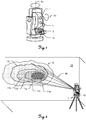
- FIG. 1 shows a surveying device 1 according to the invention with an integrated detector 2, which can be designed in particular as a thermal imaging camera, wherein the detector 2 has a detection direction as far as possible parallel to a targeting direction of a likewise arranged in the surveying device targeting device 4. Furthermore, the surveying device is provided with an output unit 3, in particular with a display, on which images 10 captured by the camera 2 can be displayed.
- the device for alignment with an object has two mutually perpendicular axes of rotation 5a, 5b. The surveying device, for example a total station, can thus be aligned by rotation of the aiming device 4 about the two axes 5a, 5b on an object and first of this object an image 10, in particular with temperature information detect.
- a measurement along the straight lines 14a, 14b can be carried out and points with the smallest and at the same time points with the highest recorded temperatures can be located thereon.
- statements about the temperature profile or the extent of one of the several temperature ranges 11a-e can be made, wherein not the entire spatially detected temperature range 11a-e must be measured, but the measurement of, for example, two straight lines 14a, 14b which are perpendicular to each other Center 13 cut, is sufficient.
- a temperature conspicuity 24 can be made visible in the thermal imaging 20b. This temperature conspicuousness 24 can indicate that, for example, a heat leak, caused, for example, by faulty building insulation, is present at the building.
- the heat leak 24 can be measured on the basis of the image information by means of the surveying device 1 and the position with respect to the building can be determined exactly. For this purpose, a measuring beam 30 along previously derived isotherms can be performed and measured these in a specified resolution.
- FIG. 6 shows a surveying device 1 according to the invention and a construction machine 25 in the area 28.
- the construction machine 25 has a target 26, which can be targeted by the surveying device 1 by means of a measuring beam 30.
- the target mark 26 can furthermore be thermally coded, ie the target mark 26 can be heated at least partially to a predefined temperature, for example to a defined value between 50 ° C. and 100 ° C. or, for example, to a defined value between 5 ° C. and 20 ° ° C are cooled so that a defined thereby temperature radiation emanates from the target 26.
- the choice of the temperature can be made such that a clear distinction of tempered objects from the environment is possible.
- a temperature or temperature range suitable for the respective requirements for the target mark 26 can be selected or specified. For example, at a prevailing air temperature of 40 ° C and sunshine, a temperature range of 100 ° C to 110 ° C for the target 26, at -20 ° C tempered to 30 ° C target 26 be suitable.
- the surveying device 1 has a thermal imaging camera with which the construction machine 25 and thus at the same time the defined and known tempered target 26 can be detected.
- the temperature of the target mark 26 can be determined in the surveying device 1 and its position can be derived with respect to the detection direction of the camera or with respect to the targeting direction of the targeting unit. Due to the predefined temperature of the target 26, the in the Thermal image detected target mark 26 identified on the inventive surveying device 1 and the assignment of the target 26 to a construction machine 25, the position of the construction machine 25 are determined uniquely.
- the marks 26 a and 26 b Due to the different thermal coding of the marks 26 a and 26 b they can be quickly distinguished from each other and thus the Targeting of the surveying device 1 quickly and accurately aligned to the respective target mark 26a, 26b and an accurate determination of the position of the construction machine 25a, 25b are performed.
- further target marks 26c-e are positioned in the terrain 28.
- the two marks 26c and 26e are arranged at a respective measuring point in the area 28 or on the building shown. Because these two target marks 26c and 26e again appear different on a detected thermal image, the corresponding targets can be quickly distinguished from the others, the surveying station can be aligned with them and their position determined exactly.
- Another shown aiming mark 26d is disposed on a surveying bar 41 guided by a user.
- the defined temperature-controlled target mark 26d can in turn be identified on the part of the surveying station 1 uniquely via the processing of a detected thermal image on which the target mark 26d is also included, and the temperature characteristic recorded therein.
- the reflector 41 can be aimed directly at the targeting unit of the surveying station 1 and thus the exact position of the surveying rod can be determined.
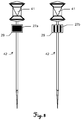
- FIG. 8 shows two surveying rods 42, each with a reflector 41, which may be configured for example as a prism.
- a coding element 29 is further arranged, which extends over a part of the surveying rod 42.
- Two different forms of coding 27a and 27b applied thereto are shown by way of example on the coding elements 29.
- the coding forms 27a and 27b respectively show dark areas on the coding elements 29, which can be tempered in a defined manner and thus can have a defined thermal coding partially or flatly in certain shapes 27a and 27b.
- three heat stiffeners 27b or a rectangular surface 27a or other geometric figures may be provided on the coding elements 29.
- Such a target tracking based on a daylight image is eg in the EP 2 141 450 described.
- the surveying station is automatically aligned with a target and pursues this, wherein the target recognition is done by means of image processing of a previously acquired environmental image.
- This system supports target tracking and target detection by means of a laser beam directed at a reflector and detected at the surveying device, in particular when the laser beam is outside a detection range and target tracking based solely on the detection of laser reflection is not feasible.
- a manual or automatic target search based on the temperature detection of the target can take place by means of image processing on a detected thermal image.
- a high-precision targeting of a target can take place automatically via the position of the target detected in the thermal image.
- the position of a thermal Kodierelements 29 exactly determined.
- the distance of the thermal coding to the reflector 41 can be known. With this additional information, it is possible to align the target unit of the surveying station directly or automatically on the reflector 41 and to determine its position exactly.
Landscapes
- Engineering & Computer Science (AREA)
- Physics & Mathematics (AREA)
- General Physics & Mathematics (AREA)
- Radar, Positioning & Navigation (AREA)
- Remote Sensing (AREA)
- Multimedia (AREA)
- Radiation Pyrometers (AREA)
- Length Measuring Devices By Optical Means (AREA)
- Image Processing (AREA)
- Geophysics And Detection Of Objects (AREA)
Applications Claiming Priority (3)
| Application Number | Priority Date | Filing Date | Title |
|---|---|---|---|
| EP11150516A EP2474808A1 (fr) | 2011-01-10 | 2011-01-10 | Appareil de mesure géodésique doté d'une caméra thermographique |
| PCT/EP2012/050302 WO2012095417A1 (fr) | 2011-01-10 | 2012-01-10 | Appareil de mesure géodésique à caméra thermographique |
| EP12702994.0A EP2663834B1 (fr) | 2011-01-10 | 2012-01-10 | Appareil de mesure géodésique à caméra thermographique |
Related Parent Applications (2)
| Application Number | Title | Priority Date | Filing Date |
|---|---|---|---|
| EP12702994.0A Division EP2663834B1 (fr) | 2011-01-10 | 2012-01-10 | Appareil de mesure géodésique à caméra thermographique |
| EP12702994.0A Division-Into EP2663834B1 (fr) | 2011-01-10 | 2012-01-10 | Appareil de mesure géodésique à caméra thermographique |
Publications (3)
| Publication Number | Publication Date |
|---|---|
| EP3339802A2 true EP3339802A2 (fr) | 2018-06-27 |
| EP3339802A3 EP3339802A3 (fr) | 2018-09-12 |
| EP3339802B1 EP3339802B1 (fr) | 2019-10-30 |
Family
ID=44021895
Family Applications (3)
| Application Number | Title | Priority Date | Filing Date |
|---|---|---|---|
| EP11150516A Withdrawn EP2474808A1 (fr) | 2011-01-10 | 2011-01-10 | Appareil de mesure géodésique doté d'une caméra thermographique |
| EP17169805.3A Active EP3339802B1 (fr) | 2011-01-10 | 2012-01-10 | Appareil de mesure géodésique doté d'une caméra thermographique |
| EP12702994.0A Active EP2663834B1 (fr) | 2011-01-10 | 2012-01-10 | Appareil de mesure géodésique à caméra thermographique |
Family Applications Before (1)
| Application Number | Title | Priority Date | Filing Date |
|---|---|---|---|
| EP11150516A Withdrawn EP2474808A1 (fr) | 2011-01-10 | 2011-01-10 | Appareil de mesure géodésique doté d'une caméra thermographique |
Family Applications After (1)
| Application Number | Title | Priority Date | Filing Date |
|---|---|---|---|
| EP12702994.0A Active EP2663834B1 (fr) | 2011-01-10 | 2012-01-10 | Appareil de mesure géodésique à caméra thermographique |
Country Status (8)
| Country | Link |
|---|---|
| US (1) | US9733081B2 (fr) |
| EP (3) | EP2474808A1 (fr) |
| KR (1) | KR101542074B1 (fr) |
| CN (1) | CN103314271B (fr) |
| AU (1) | AU2012206599B2 (fr) |
| BR (1) | BR112013017112A2 (fr) |
| CA (1) | CA2822387C (fr) |
| WO (1) | WO2012095417A1 (fr) |
Cited By (1)
| Publication number | Priority date | Publication date | Assignee | Title |
|---|---|---|---|---|
| EP4411658A4 (fr) * | 2021-09-27 | 2025-05-07 | Sony Semiconductor Solutions Corporation | Dispositif de traitement d'informations et procédé de traitement d'informations |
Families Citing this family (21)
| Publication number | Priority date | Publication date | Assignee | Title |
|---|---|---|---|---|
| DE112013004369T5 (de) | 2012-09-06 | 2015-06-11 | Faro Technologies, Inc. | Laserscanner mit zusätzlicher Erfassungsvorrichtung |
| DE112013004489T5 (de) | 2012-09-14 | 2015-05-28 | Faro Technologies, Inc. | Laserscanner mit Dynamischer Einstellung der Winkel-Abtastgeschwindigkeit |
| DE102012217282B4 (de) * | 2012-09-25 | 2023-03-02 | Trimble Jena Gmbh | Verfahren und Vorrichtung zur Zuordnung von Messpunkten zu einem Satz von Festpunkten |
| US9367962B2 (en) * | 2013-10-22 | 2016-06-14 | Topcon Positioning Systems, Inc. | Augmented image display using a camera and a position and orientation sensor |
| US9633246B2 (en) * | 2014-09-26 | 2017-04-25 | Trimble Inc. | Integrated auto-level and electronic rod reader |
| US9354057B2 (en) | 2014-09-26 | 2016-05-31 | Trimble Navigation Limited | Electronic rod reader and field notebook |
| KR101635000B1 (ko) | 2015-06-26 | 2016-07-08 | (주) 비엑스 솔루션 | 복수의 카메라를 이용한 화재감지장치 및 그 시스템 |
| KR101904282B1 (ko) | 2016-12-20 | 2018-10-30 | 주식회사 해강에이피 | 화재 징후 예방 및 냄새 감지기 시스템 |
| US11288834B2 (en) * | 2017-05-23 | 2022-03-29 | Brainlab Ag | Determining the relative position between a point cloud generating camera and another camera |
| KR101953626B1 (ko) * | 2017-06-29 | 2019-03-06 | 서강대학교산학협력단 | 다중 히스토그램을 이용한 객체 추적 방법 및 이를 이용한 객체 추적 시스템 |
| US11887449B2 (en) * | 2017-07-13 | 2024-01-30 | Elvis Maksuti | Programmable infrared security system |
| JP7084705B2 (ja) | 2017-09-13 | 2022-06-15 | 株式会社トプコン | 測量装置 |
| WO2019104583A1 (fr) * | 2017-11-30 | 2019-06-06 | 深圳市大疆创新科技有限公司 | Procédé, dispositif et drone de suivi de point de température maximale |
| EP3935358A1 (fr) * | 2019-03-06 | 2022-01-12 | Electric Pocket Limited | Mappages de qualité thermique |
| US11917287B2 (en) * | 2019-07-31 | 2024-02-27 | Virtualine Pty Ltd | System for aligning an item along a path in an area |
| JP7285174B2 (ja) * | 2019-09-04 | 2023-06-01 | 株式会社トプコン | 壁面のひび割れ測定機および測定方法 |
| DE102020122546B4 (de) | 2020-08-28 | 2022-12-01 | BTA GmbH | System zur Überwachung des Vortriebs von Vortriebsmaschinen, insbesondere von Tunnelbohrmaschinen |
| CN114235058B (zh) * | 2022-02-23 | 2022-05-06 | 山东省地质矿产勘查开发局第四地质大队(山东省第四地质矿产勘查院) | 一种用于矿产地质的矿坑数据测量设备 |
| TWI806448B (zh) * | 2022-02-24 | 2023-06-21 | 群光電子股份有限公司 | 溫度量測系統、溫度量測方法及非暫態電腦可讀取儲存媒體 |
| US12247825B2 (en) * | 2022-04-13 | 2025-03-11 | Keller North America, Inc. | Flush-mount deformation monitoring system |
| CN119164516B (zh) * | 2024-11-14 | 2025-03-04 | 南昌轨道交通集团有限公司 | 一种井内冻结法施工用温度监测管理系统 |
Citations (3)
| Publication number | Priority date | Publication date | Assignee | Title |
|---|---|---|---|---|
| EP1314959A1 (fr) | 2001-11-22 | 2003-05-28 | Leica Geosystems AG | Dispositif électronique visualiseur et contrôleur pour appareil de mesure |
| WO2004036145A1 (fr) | 2002-10-12 | 2004-04-29 | Leica Geosystems Ag | Dispositif d'affichage et de commande electronique destine a un appareil de mesure |
| EP2141450A1 (fr) | 2008-07-05 | 2010-01-06 | Kabushiki Kaisha TOPCON | Dispositif d'arpentage et procédé de suivi automatique |
Family Cites Families (25)
| Publication number | Priority date | Publication date | Assignee | Title |
|---|---|---|---|---|
| US3471234A (en) * | 1966-06-08 | 1969-10-07 | Process Equipment Co Of Tipp C | Laser beam projector for surveying operations |
| US4086841A (en) * | 1971-09-03 | 1978-05-02 | Macdonald Gilmour C | Helical path munitions delivery |
| US4347739A (en) * | 1980-05-27 | 1982-09-07 | Jenoptik Jena Gmbh | Measuring equipment for the determination of terrestrial refraction |
| AT375153B (de) | 1982-09-23 | 1984-07-10 | Voest Alpine Ag | Einrichtung zur erfassung der position des schraemkopfes einer vortriebs- oder gewinnungsmaschine |
| US4910593A (en) * | 1989-04-14 | 1990-03-20 | Entech Engineering, Inc. | System for geological defect detection utilizing composite video-infrared thermography |
| JP2826753B2 (ja) * | 1989-12-14 | 1998-11-18 | 株式会社オプテック | 路面測定装置 |
| US5386117B1 (en) * | 1993-06-07 | 1997-06-10 | Computational Systems Inc | Infrared thermography system including mobile unit |
| CH687653A5 (de) * | 1994-03-17 | 1997-01-15 | Von Roll Umwelttechnik Ag | Brandueberwachungssystem. |
| DE59901809D1 (de) * | 1999-08-31 | 2002-07-25 | Leica Geosystems Ag | Tachymeter-Fernrohr |
| EP1460377A3 (fr) * | 2003-03-21 | 2004-09-29 | Leica Geosystems AG | Procédé et dispositif pour traitement d'image dans un appareil de mesure géodésique |
| US7277053B2 (en) * | 2004-09-08 | 2007-10-02 | Lucid Dimensions, Llc | Apparatus and methods for detecting and locating signals |
| US7804981B2 (en) * | 2005-01-13 | 2010-09-28 | Sensis Corporation | Method and system for tracking position of an object using imaging and non-imaging surveillance devices |
| EP1734336A1 (fr) * | 2005-06-13 | 2006-12-20 | Leica Geosystems AG | Cible d'arpentage et système d'arpentage |
| US7541581B2 (en) * | 2005-10-18 | 2009-06-02 | Insight Technology Incorporated | Clip-on infrared imager |
| US8026842B2 (en) * | 2006-06-08 | 2011-09-27 | Vista Research, Inc. | Method for surveillance to detect a land target |
| US20080123903A1 (en) * | 2006-07-03 | 2008-05-29 | Pentax Industrial Instruments Co., Ltd. | Surveying apparatus |
| US20100265329A1 (en) * | 2006-10-06 | 2010-10-21 | Doneker Robert L | Lightweight platform for remote sensing of point source mixing and system for mixing model validation and calibration |
| ES2438976T3 (es) * | 2007-05-11 | 2014-01-21 | Saab Ab | Dispositivo y procedimiento para un aparato de visión |
| EP2053353A1 (fr) * | 2007-10-26 | 2009-04-29 | Leica Geosystems AG | Procédé de mesure de la distance et appareil similaire |
| US8643716B1 (en) * | 2008-02-13 | 2014-02-04 | Power Survey Llc | Method and system for mobile steam leak detection |
| DE102008002241A1 (de) * | 2008-06-05 | 2009-12-10 | Robert Bosch Gmbh | Verfahren und Messsystem zur bildbasierten Vermessung eines Raumes |
| IL192601A (en) * | 2008-07-03 | 2014-07-31 | Elta Systems Ltd | Discovery / Transmission Device, System and Method |
| US8400619B1 (en) * | 2008-08-22 | 2013-03-19 | Intelligent Automation, Inc. | Systems and methods for automatic target tracking and beam steering |
| DE102009039016B4 (de) * | 2009-08-28 | 2012-05-03 | Deutsches Zentrum für Luft- und Raumfahrt e.V. | Strömungsermittlungsverfahren |
| KR101221663B1 (ko) | 2012-05-30 | 2013-01-14 | 대한항업(주) | 토탈스테이션의 데이터를 처리하는 측지측량 데이터 수집전용 통합관리시스템 |
-
2011
- 2011-01-10 EP EP11150516A patent/EP2474808A1/fr not_active Withdrawn
-
2012
- 2012-01-10 US US13/978,737 patent/US9733081B2/en active Active
- 2012-01-10 KR KR1020137020906A patent/KR101542074B1/ko not_active Expired - Fee Related
- 2012-01-10 CA CA2822387A patent/CA2822387C/fr not_active Expired - Fee Related
- 2012-01-10 CN CN201280004223.4A patent/CN103314271B/zh active Active
- 2012-01-10 BR BR112013017112-0A patent/BR112013017112A2/pt not_active Application Discontinuation
- 2012-01-10 EP EP17169805.3A patent/EP3339802B1/fr active Active
- 2012-01-10 EP EP12702994.0A patent/EP2663834B1/fr active Active
- 2012-01-10 WO PCT/EP2012/050302 patent/WO2012095417A1/fr not_active Ceased
- 2012-01-10 AU AU2012206599A patent/AU2012206599B2/en not_active Ceased
Patent Citations (3)
| Publication number | Priority date | Publication date | Assignee | Title |
|---|---|---|---|---|
| EP1314959A1 (fr) | 2001-11-22 | 2003-05-28 | Leica Geosystems AG | Dispositif électronique visualiseur et contrôleur pour appareil de mesure |
| WO2004036145A1 (fr) | 2002-10-12 | 2004-04-29 | Leica Geosystems Ag | Dispositif d'affichage et de commande electronique destine a un appareil de mesure |
| EP2141450A1 (fr) | 2008-07-05 | 2010-01-06 | Kabushiki Kaisha TOPCON | Dispositif d'arpentage et procédé de suivi automatique |
Cited By (1)
| Publication number | Priority date | Publication date | Assignee | Title |
|---|---|---|---|---|
| EP4411658A4 (fr) * | 2021-09-27 | 2025-05-07 | Sony Semiconductor Solutions Corporation | Dispositif de traitement d'informations et procédé de traitement d'informations |
Also Published As
| Publication number | Publication date |
|---|---|
| US20130278759A1 (en) | 2013-10-24 |
| CA2822387A1 (fr) | 2012-07-19 |
| CN103314271A (zh) | 2013-09-18 |
| EP2663834A1 (fr) | 2013-11-20 |
| AU2012206599B2 (en) | 2014-07-24 |
| EP3339802B1 (fr) | 2019-10-30 |
| WO2012095417A1 (fr) | 2012-07-19 |
| BR112013017112A2 (pt) | 2020-10-27 |
| EP3339802A3 (fr) | 2018-09-12 |
| EP2663834B1 (fr) | 2018-06-27 |
| AU2012206599A1 (en) | 2013-06-20 |
| EP2474808A1 (fr) | 2012-07-11 |
| CN103314271B (zh) | 2016-10-26 |
| KR20130114715A (ko) | 2013-10-17 |
| KR101542074B1 (ko) | 2015-08-12 |
| US9733081B2 (en) | 2017-08-15 |
| CA2822387C (fr) | 2016-03-29 |
Similar Documents
| Publication | Publication Date | Title |
|---|---|---|
| EP3339802B1 (fr) | Appareil de mesure géodésique doté d'une caméra thermographique | |
| EP2787322B1 (fr) | Référencement géodésique de nuages de points | |
| EP1606581B1 (fr) | Procede et dispositif de traitement d'image d'un appareil de mesure geodesique | |
| EP2787321B1 (fr) | Détermination de surface d'objets à l'aide de la détermination d'un seul point précis géodésique et du balayage | |
| EP2646771B1 (fr) | Instrument d'arpentage robotique et procédé pour l'autocollimation automatisée d'un télescope d'un instrument d'arpentage avec une cible d'autocollimation | |
| DE69411831T2 (de) | Verfahren und Vorrichtung zur Temperaturmessung mittels Infrarottechnik | |
| DE112012005524B4 (de) | Verfahren zur mechanischen Übermittlung eines Befehls zur Steuerung des Betriebs eines Lasertrackers | |
| EP2761251B1 (fr) | Système de mesure et procédé de jalonnement d'un point cible connu dans un système de coordonnées | |
| EP2591311B1 (fr) | Appareil de mesure géodésique doté d'une fonction de ciblage de point cible haute précision et automatique | |
| EP2663835B1 (fr) | Appareil de mesure à fonctionnalité de changement de représentation automatique | |
| EP2737278B1 (fr) | Dispositif de mesure commandable sans contact et son procédé de commande | |
| EP1517117A1 (fr) | Méthode et système pour la détermination de la position actuelle d'un appareil de postionement | |
| EP2620746A1 (fr) | Dispositif d'arpentage doté d'une fonctionnalité de balayage et d'un mode de mesure à point unique | |
| WO2014161882A1 (fr) | Appareil d'arpentage doté d'une fonction d'étalonnage d'une position d'image visualisée sur un réticule électronique | |
| EP2194399A1 (fr) | Procédé de détermination de position et système de mesure géodésique | |
| EP2171556B1 (fr) | Dispositif et procédé de détermination de position et d'orientation | |
| EP4254020A2 (fr) | Système et procédé de surveillance d'un espace d'air pour un site étendu | |
| DE102010005042B3 (de) | IR-Temperaturmesseinrichtung und Verfahren zur Bestimmung der tatsächlichen Lage eines Messflecks einer IR-Temperaturmesseinrichtung | |
| DE102016200877A1 (de) | System zum Messen einer dreidimensionalen Position | |
| EP2756261B1 (fr) | Appareil de mesure et procédé de représentation filtrée d'informations d'objets | |
| DE102016200967A1 (de) | System zum Messen einer dreidimensionalen Position | |
| DE102005043070A1 (de) | Verfahren zur hochgenauen dreidimensionalen Vermessung und/oder Rekonstruktion von Objekten mit Hilfe digitaler Bildaufnahmen, beispielsweise zur Bildauswertung von Verkehrsstrecken | |
| DE102004051513A1 (de) | Verfahren und Vorrichtung zur Bestimmung einer abweichenden Temperaturverteilung mittels eines Pyrometers | |
| DE102006014546A1 (de) | Verfahren und Vorrichtung zum sensorbasierten Überwachen einer Umgebung |
Legal Events
| Date | Code | Title | Description |
|---|---|---|---|
| PUAI | Public reference made under article 153(3) epc to a published international application that has entered the european phase |
Free format text: ORIGINAL CODE: 0009012 |
|
| STAA | Information on the status of an ep patent application or granted ep patent |
Free format text: STATUS: THE APPLICATION HAS BEEN PUBLISHED |
|
| AC | Divisional application: reference to earlier application |
Ref document number: 2663834 Country of ref document: EP Kind code of ref document: P |
|
| AK | Designated contracting states |
Kind code of ref document: A2 Designated state(s): AL AT BE BG CH CY CZ DE DK EE ES FI FR GB GR HR HU IE IS IT LI LT LU LV MC MK MT NL NO PL PT RO RS SE SI SK SM TR |
|
| PUAL | Search report despatched |
Free format text: ORIGINAL CODE: 0009013 |
|
| AK | Designated contracting states |
Kind code of ref document: A3 Designated state(s): AL AT BE BG CH CY CZ DE DK EE ES FI FR GB GR HR HU IE IS IT LI LT LU LV MC MK MT NL NO PL PT RO RS SE SI SK SM TR |
|
| RIC1 | Information provided on ipc code assigned before grant |
Ipc: G01C 1/04 20060101AFI20180807BHEP Ipc: G01C 15/00 20060101ALI20180807BHEP Ipc: G01C 7/00 20060101ALI20180807BHEP Ipc: G01C 15/06 20060101ALI20180807BHEP |
|
| STAA | Information on the status of an ep patent application or granted ep patent |
Free format text: STATUS: REQUEST FOR EXAMINATION WAS MADE |
|
| 17P | Request for examination filed |
Effective date: 20190312 |
|
| RBV | Designated contracting states (corrected) |
Designated state(s): AL AT BE BG CH CY CZ DE DK EE ES FI FR GB GR HR HU IE IS IT LI LT LU LV MC MK MT NL NO PL PT RO RS SE SI SK SM TR |
|
| GRAP | Despatch of communication of intention to grant a patent |
Free format text: ORIGINAL CODE: EPIDOSNIGR1 |
|
| STAA | Information on the status of an ep patent application or granted ep patent |
Free format text: STATUS: GRANT OF PATENT IS INTENDED |
|
| INTG | Intention to grant announced |
Effective date: 20190628 |
|
| RIN1 | Information on inventor provided before grant (corrected) |
Inventor name: SIEBER, STEFAN Inventor name: LEGRAND, VINCENT Inventor name: MOELLER, BERND Inventor name: ZIMMERMANN, JAN Inventor name: KOTZUR, NORBERT |
|
| GRAS | Grant fee paid |
Free format text: ORIGINAL CODE: EPIDOSNIGR3 |
|
| GRAA | (expected) grant |
Free format text: ORIGINAL CODE: 0009210 |
|
| STAA | Information on the status of an ep patent application or granted ep patent |
Free format text: STATUS: THE PATENT HAS BEEN GRANTED |
|
| AC | Divisional application: reference to earlier application |
Ref document number: 2663834 Country of ref document: EP Kind code of ref document: P |
|
| AK | Designated contracting states |
Kind code of ref document: B1 Designated state(s): AL AT BE BG CH CY CZ DE DK EE ES FI FR GB GR HR HU IE IS IT LI LT LU LV MC MK MT NL NO PL PT RO RS SE SI SK SM TR |
|
| REG | Reference to a national code |
Ref country code: GB Ref legal event code: FG4D Free format text: NOT ENGLISH |
|
| REG | Reference to a national code |
Ref country code: CH Ref legal event code: EP |
|
| REG | Reference to a national code |
Ref country code: CH Ref legal event code: NV Representative=s name: KAMINSKI HARMANN PATENTANWAELTE AG, LI Ref country code: AT Ref legal event code: REF Ref document number: 1196630 Country of ref document: AT Kind code of ref document: T Effective date: 20191115 |
|
| REG | Reference to a national code |
Ref country code: DE Ref legal event code: R096 Ref document number: 502012015472 Country of ref document: DE |
|
| REG | Reference to a national code |
Ref country code: IE Ref legal event code: FG4D Free format text: LANGUAGE OF EP DOCUMENT: GERMAN |
|
| REG | Reference to a national code |
Ref country code: NL Ref legal event code: FP |
|
| REG | Reference to a national code |
Ref country code: SE Ref legal event code: TRGR |
|
| REG | Reference to a national code |
Ref country code: LT Ref legal event code: MG4D |
|
| PG25 | Lapsed in a contracting state [announced via postgrant information from national office to epo] |
Ref country code: PT Free format text: LAPSE BECAUSE OF FAILURE TO SUBMIT A TRANSLATION OF THE DESCRIPTION OR TO PAY THE FEE WITHIN THE PRESCRIBED TIME-LIMIT Effective date: 20200302 Ref country code: LV Free format text: LAPSE BECAUSE OF FAILURE TO SUBMIT A TRANSLATION OF THE DESCRIPTION OR TO PAY THE FEE WITHIN THE PRESCRIBED TIME-LIMIT Effective date: 20191030 Ref country code: NO Free format text: LAPSE BECAUSE OF FAILURE TO SUBMIT A TRANSLATION OF THE DESCRIPTION OR TO PAY THE FEE WITHIN THE PRESCRIBED TIME-LIMIT Effective date: 20200130 Ref country code: GR Free format text: LAPSE BECAUSE OF FAILURE TO SUBMIT A TRANSLATION OF THE DESCRIPTION OR TO PAY THE FEE WITHIN THE PRESCRIBED TIME-LIMIT Effective date: 20200131 Ref country code: PL Free format text: LAPSE BECAUSE OF FAILURE TO SUBMIT A TRANSLATION OF THE DESCRIPTION OR TO PAY THE FEE WITHIN THE PRESCRIBED TIME-LIMIT Effective date: 20191030 Ref country code: BG Free format text: LAPSE BECAUSE OF FAILURE TO SUBMIT A TRANSLATION OF THE DESCRIPTION OR TO PAY THE FEE WITHIN THE PRESCRIBED TIME-LIMIT Effective date: 20200130 Ref country code: FI Free format text: LAPSE BECAUSE OF FAILURE TO SUBMIT A TRANSLATION OF THE DESCRIPTION OR TO PAY THE FEE WITHIN THE PRESCRIBED TIME-LIMIT Effective date: 20191030 Ref country code: LT Free format text: LAPSE BECAUSE OF FAILURE TO SUBMIT A TRANSLATION OF THE DESCRIPTION OR TO PAY THE FEE WITHIN THE PRESCRIBED TIME-LIMIT Effective date: 20191030 |
|
| PGFP | Annual fee paid to national office [announced via postgrant information from national office to epo] |
Ref country code: NL Payment date: 20200121 Year of fee payment: 9 Ref country code: SE Payment date: 20200121 Year of fee payment: 9 |
|
| PG25 | Lapsed in a contracting state [announced via postgrant information from national office to epo] |
Ref country code: IS Free format text: LAPSE BECAUSE OF FAILURE TO SUBMIT A TRANSLATION OF THE DESCRIPTION OR TO PAY THE FEE WITHIN THE PRESCRIBED TIME-LIMIT Effective date: 20200229 Ref country code: RS Free format text: LAPSE BECAUSE OF FAILURE TO SUBMIT A TRANSLATION OF THE DESCRIPTION OR TO PAY THE FEE WITHIN THE PRESCRIBED TIME-LIMIT Effective date: 20191030 Ref country code: HR Free format text: LAPSE BECAUSE OF FAILURE TO SUBMIT A TRANSLATION OF THE DESCRIPTION OR TO PAY THE FEE WITHIN THE PRESCRIBED TIME-LIMIT Effective date: 20191030 |
|
| PG25 | Lapsed in a contracting state [announced via postgrant information from national office to epo] |
Ref country code: AL Free format text: LAPSE BECAUSE OF FAILURE TO SUBMIT A TRANSLATION OF THE DESCRIPTION OR TO PAY THE FEE WITHIN THE PRESCRIBED TIME-LIMIT Effective date: 20191030 |
|
| PG25 | Lapsed in a contracting state [announced via postgrant information from national office to epo] |
Ref country code: RO Free format text: LAPSE BECAUSE OF FAILURE TO SUBMIT A TRANSLATION OF THE DESCRIPTION OR TO PAY THE FEE WITHIN THE PRESCRIBED TIME-LIMIT Effective date: 20191030 Ref country code: DK Free format text: LAPSE BECAUSE OF FAILURE TO SUBMIT A TRANSLATION OF THE DESCRIPTION OR TO PAY THE FEE WITHIN THE PRESCRIBED TIME-LIMIT Effective date: 20191030 Ref country code: EE Free format text: LAPSE BECAUSE OF FAILURE TO SUBMIT A TRANSLATION OF THE DESCRIPTION OR TO PAY THE FEE WITHIN THE PRESCRIBED TIME-LIMIT Effective date: 20191030 Ref country code: ES Free format text: LAPSE BECAUSE OF FAILURE TO SUBMIT A TRANSLATION OF THE DESCRIPTION OR TO PAY THE FEE WITHIN THE PRESCRIBED TIME-LIMIT Effective date: 20191030 Ref country code: CZ Free format text: LAPSE BECAUSE OF FAILURE TO SUBMIT A TRANSLATION OF THE DESCRIPTION OR TO PAY THE FEE WITHIN THE PRESCRIBED TIME-LIMIT Effective date: 20191030 |
|
| REG | Reference to a national code |
Ref country code: DE Ref legal event code: R097 Ref document number: 502012015472 Country of ref document: DE |
|
| PG25 | Lapsed in a contracting state [announced via postgrant information from national office to epo] |
Ref country code: SM Free format text: LAPSE BECAUSE OF FAILURE TO SUBMIT A TRANSLATION OF THE DESCRIPTION OR TO PAY THE FEE WITHIN THE PRESCRIBED TIME-LIMIT Effective date: 20191030 Ref country code: SK Free format text: LAPSE BECAUSE OF FAILURE TO SUBMIT A TRANSLATION OF THE DESCRIPTION OR TO PAY THE FEE WITHIN THE PRESCRIBED TIME-LIMIT Effective date: 20191030 Ref country code: MC Free format text: LAPSE BECAUSE OF FAILURE TO SUBMIT A TRANSLATION OF THE DESCRIPTION OR TO PAY THE FEE WITHIN THE PRESCRIBED TIME-LIMIT Effective date: 20191030 |
|
| PLBE | No opposition filed within time limit |
Free format text: ORIGINAL CODE: 0009261 |
|
| STAA | Information on the status of an ep patent application or granted ep patent |
Free format text: STATUS: NO OPPOSITION FILED WITHIN TIME LIMIT |
|
| 26N | No opposition filed |
Effective date: 20200731 |
|
| REG | Reference to a national code |
Ref country code: BE Ref legal event code: MM Effective date: 20200131 |
|
| PG25 | Lapsed in a contracting state [announced via postgrant information from national office to epo] |
Ref country code: LU Free format text: LAPSE BECAUSE OF NON-PAYMENT OF DUE FEES Effective date: 20200110 |
|
| PG25 | Lapsed in a contracting state [announced via postgrant information from national office to epo] |
Ref country code: BE Free format text: LAPSE BECAUSE OF NON-PAYMENT OF DUE FEES Effective date: 20200131 Ref country code: SI Free format text: LAPSE BECAUSE OF FAILURE TO SUBMIT A TRANSLATION OF THE DESCRIPTION OR TO PAY THE FEE WITHIN THE PRESCRIBED TIME-LIMIT Effective date: 20191030 |
|
| PG25 | Lapsed in a contracting state [announced via postgrant information from national office to epo] |
Ref country code: IE Free format text: LAPSE BECAUSE OF NON-PAYMENT OF DUE FEES Effective date: 20200110 |
|
| REG | Reference to a national code |
Ref country code: AT Ref legal event code: MM01 Ref document number: 1196630 Country of ref document: AT Kind code of ref document: T Effective date: 20200110 |
|
| PG25 | Lapsed in a contracting state [announced via postgrant information from national office to epo] |
Ref country code: AT Free format text: LAPSE BECAUSE OF NON-PAYMENT OF DUE FEES Effective date: 20200110 |
|
| REG | Reference to a national code |
Ref country code: SE Ref legal event code: EUG |
|
| REG | Reference to a national code |
Ref country code: NL Ref legal event code: MM Effective date: 20210201 |
|
| PG25 | Lapsed in a contracting state [announced via postgrant information from national office to epo] |
Ref country code: NL Free format text: LAPSE BECAUSE OF NON-PAYMENT OF DUE FEES Effective date: 20210201 |
|
| PG25 | Lapsed in a contracting state [announced via postgrant information from national office to epo] |
Ref country code: SE Free format text: LAPSE BECAUSE OF NON-PAYMENT OF DUE FEES Effective date: 20210111 |
|
| PG25 | Lapsed in a contracting state [announced via postgrant information from national office to epo] |
Ref country code: TR Free format text: LAPSE BECAUSE OF FAILURE TO SUBMIT A TRANSLATION OF THE DESCRIPTION OR TO PAY THE FEE WITHIN THE PRESCRIBED TIME-LIMIT Effective date: 20191030 Ref country code: MT Free format text: LAPSE BECAUSE OF FAILURE TO SUBMIT A TRANSLATION OF THE DESCRIPTION OR TO PAY THE FEE WITHIN THE PRESCRIBED TIME-LIMIT Effective date: 20191030 Ref country code: CY Free format text: LAPSE BECAUSE OF FAILURE TO SUBMIT A TRANSLATION OF THE DESCRIPTION OR TO PAY THE FEE WITHIN THE PRESCRIBED TIME-LIMIT Effective date: 20191030 |
|
| PG25 | Lapsed in a contracting state [announced via postgrant information from national office to epo] |
Ref country code: MK Free format text: LAPSE BECAUSE OF FAILURE TO SUBMIT A TRANSLATION OF THE DESCRIPTION OR TO PAY THE FEE WITHIN THE PRESCRIBED TIME-LIMIT Effective date: 20191030 |
|
| REG | Reference to a national code |
Ref country code: CH Ref legal event code: U11 Free format text: ST27 STATUS EVENT CODE: U-0-0-U10-U11 (AS PROVIDED BY THE NATIONAL OFFICE) Effective date: 20260201 |
|
| PGFP | Annual fee paid to national office [announced via postgrant information from national office to epo] |
Ref country code: GB Payment date: 20260123 Year of fee payment: 15 |
|
| PGFP | Annual fee paid to national office [announced via postgrant information from national office to epo] |
Ref country code: DE Payment date: 20260121 Year of fee payment: 15 |
|
| PGFP | Annual fee paid to national office [announced via postgrant information from national office to epo] |
Ref country code: IT Payment date: 20260126 Year of fee payment: 15 |
|
| PGFP | Annual fee paid to national office [announced via postgrant information from national office to epo] |
Ref country code: FR Payment date: 20260123 Year of fee payment: 15 |
|
| PGFP | Annual fee paid to national office [announced via postgrant information from national office to epo] |
Ref country code: CH Payment date: 20260201 Year of fee payment: 15 |