EP3339841B1 - Dispositif de détection de lumière - Google Patents
Dispositif de détection de lumière Download PDFInfo
- Publication number
- EP3339841B1 EP3339841B1 EP15902196.3A EP15902196A EP3339841B1 EP 3339841 B1 EP3339841 B1 EP 3339841B1 EP 15902196 A EP15902196 A EP 15902196A EP 3339841 B1 EP3339841 B1 EP 3339841B1
- Authority
- EP
- European Patent Office
- Prior art keywords
- laser beam
- channels
- droplets
- light detection
- oil
- Prior art date
- Legal status (The legal status is an assumption and is not a legal conclusion. Google has not performed a legal analysis and makes no representation as to the accuracy of the status listed.)
- Active
Links
Images












Classifications
-
- G—PHYSICS
- G01—MEASURING; TESTING
- G01N—INVESTIGATING OR ANALYSING MATERIALS BY DETERMINING THEIR CHEMICAL OR PHYSICAL PROPERTIES
- G01N21/00—Investigating or analysing materials by the use of optical means, i.e. using sub-millimetre waves, infrared, visible or ultraviolet light
- G01N21/62—Systems in which the material investigated is excited whereby it emits light or causes a change in wavelength of the incident light
- G01N21/63—Systems in which the material investigated is excited whereby it emits light or causes a change in wavelength of the incident light optically excited
- G01N21/64—Fluorescence; Phosphorescence
- G01N21/6428—Measuring fluorescence of fluorescent products of reactions or of fluorochrome labelled reactive substances, e.g. measuring quenching effects, using measuring "optrodes"
-
- G—PHYSICS
- G01—MEASURING; TESTING
- G01N—INVESTIGATING OR ANALYSING MATERIALS BY DETERMINING THEIR CHEMICAL OR PHYSICAL PROPERTIES
- G01N21/00—Investigating or analysing materials by the use of optical means, i.e. using sub-millimetre waves, infrared, visible or ultraviolet light
- G01N21/62—Systems in which the material investigated is excited whereby it emits light or causes a change in wavelength of the incident light
- G01N21/63—Systems in which the material investigated is excited whereby it emits light or causes a change in wavelength of the incident light optically excited
- G01N21/64—Fluorescence; Phosphorescence
- G01N21/645—Specially adapted constructive features of fluorimeters
-
- B—PERFORMING OPERATIONS; TRANSPORTING
- B01—PHYSICAL OR CHEMICAL PROCESSES OR APPARATUS IN GENERAL
- B01L—CHEMICAL OR PHYSICAL LABORATORY APPARATUS FOR GENERAL USE
- B01L3/00—Containers or dishes for laboratory use, e.g. laboratory glassware; Droppers
- B01L3/50—Containers for the purpose of retaining a material to be analysed, e.g. test tubes
- B01L3/502—Containers for the purpose of retaining a material to be analysed, e.g. test tubes with fluid transport, e.g. in multi-compartment structures
- B01L3/5027—Containers for the purpose of retaining a material to be analysed, e.g. test tubes with fluid transport, e.g. in multi-compartment structures by integrated microfluidic structures, i.e. dimensions of channels and chambers are such that surface tension forces are important, e.g. lab-on-a-chip
- B01L3/502715—Containers for the purpose of retaining a material to be analysed, e.g. test tubes with fluid transport, e.g. in multi-compartment structures by integrated microfluidic structures, i.e. dimensions of channels and chambers are such that surface tension forces are important, e.g. lab-on-a-chip characterised by interfacing components, e.g. fluidic, electrical, optical or mechanical interfaces
-
- B—PERFORMING OPERATIONS; TRANSPORTING
- B01—PHYSICAL OR CHEMICAL PROCESSES OR APPARATUS IN GENERAL
- B01L—CHEMICAL OR PHYSICAL LABORATORY APPARATUS FOR GENERAL USE
- B01L3/00—Containers or dishes for laboratory use, e.g. laboratory glassware; Droppers
- B01L3/50—Containers for the purpose of retaining a material to be analysed, e.g. test tubes
- B01L3/502—Containers for the purpose of retaining a material to be analysed, e.g. test tubes with fluid transport, e.g. in multi-compartment structures
- B01L3/5027—Containers for the purpose of retaining a material to be analysed, e.g. test tubes with fluid transport, e.g. in multi-compartment structures by integrated microfluidic structures, i.e. dimensions of channels and chambers are such that surface tension forces are important, e.g. lab-on-a-chip
- B01L3/502769—Containers for the purpose of retaining a material to be analysed, e.g. test tubes with fluid transport, e.g. in multi-compartment structures by integrated microfluidic structures, i.e. dimensions of channels and chambers are such that surface tension forces are important, e.g. lab-on-a-chip characterised by multiphase flow arrangements
- B01L3/502784—Containers for the purpose of retaining a material to be analysed, e.g. test tubes with fluid transport, e.g. in multi-compartment structures by integrated microfluidic structures, i.e. dimensions of channels and chambers are such that surface tension forces are important, e.g. lab-on-a-chip characterised by multiphase flow arrangements specially adapted for droplet or plug flow, e.g. digital microfluidics
-
- B—PERFORMING OPERATIONS; TRANSPORTING
- B01—PHYSICAL OR CHEMICAL PROCESSES OR APPARATUS IN GENERAL
- B01L—CHEMICAL OR PHYSICAL LABORATORY APPARATUS FOR GENERAL USE
- B01L7/00—Heating or cooling apparatus; Heat insulating devices
- B01L7/52—Heating or cooling apparatus; Heat insulating devices with provision for submitting samples to a predetermined sequence of different temperatures, e.g. for treating nucleic acid samples
-
- G—PHYSICS
- G01—MEASURING; TESTING
- G01N—INVESTIGATING OR ANALYSING MATERIALS BY DETERMINING THEIR CHEMICAL OR PHYSICAL PROPERTIES
- G01N21/00—Investigating or analysing materials by the use of optical means, i.e. using sub-millimetre waves, infrared, visible or ultraviolet light
- G01N21/62—Systems in which the material investigated is excited whereby it emits light or causes a change in wavelength of the incident light
- G01N21/63—Systems in which the material investigated is excited whereby it emits light or causes a change in wavelength of the incident light optically excited
- G01N21/64—Fluorescence; Phosphorescence
- G01N21/6486—Measuring fluorescence of biological material, e.g. DNA, RNA, cells
-
- B—PERFORMING OPERATIONS; TRANSPORTING
- B01—PHYSICAL OR CHEMICAL PROCESSES OR APPARATUS IN GENERAL
- B01L—CHEMICAL OR PHYSICAL LABORATORY APPARATUS FOR GENERAL USE
- B01L2300/00—Additional constructional details
- B01L2300/06—Auxiliary integrated devices, integrated components
- B01L2300/0627—Sensor or part of a sensor is integrated
-
- B—PERFORMING OPERATIONS; TRANSPORTING
- B01—PHYSICAL OR CHEMICAL PROCESSES OR APPARATUS IN GENERAL
- B01L—CHEMICAL OR PHYSICAL LABORATORY APPARATUS FOR GENERAL USE
- B01L2300/00—Additional constructional details
- B01L2300/08—Geometry, shape and general structure
- B01L2300/0809—Geometry, shape and general structure rectangular shaped
- B01L2300/0816—Cards, e.g. flat sample carriers usually with flow in two horizontal directions
-
- B—PERFORMING OPERATIONS; TRANSPORTING
- B01—PHYSICAL OR CHEMICAL PROCESSES OR APPARATUS IN GENERAL
- B01L—CHEMICAL OR PHYSICAL LABORATORY APPARATUS FOR GENERAL USE
- B01L2400/00—Moving or stopping fluids
- B01L2400/04—Moving fluids with specific forces or mechanical means
- B01L2400/0475—Moving fluids with specific forces or mechanical means specific mechanical means and fluid pressure
- B01L2400/0487—Moving fluids with specific forces or mechanical means specific mechanical means and fluid pressure fluid pressure, pneumatics
- B01L2400/049—Moving fluids with specific forces or mechanical means specific mechanical means and fluid pressure fluid pressure, pneumatics vacuum
-
- B—PERFORMING OPERATIONS; TRANSPORTING
- B01—PHYSICAL OR CHEMICAL PROCESSES OR APPARATUS IN GENERAL
- B01L—CHEMICAL OR PHYSICAL LABORATORY APPARATUS FOR GENERAL USE
- B01L3/00—Containers or dishes for laboratory use, e.g. laboratory glassware; Droppers
- B01L3/50—Containers for the purpose of retaining a material to be analysed, e.g. test tubes
- B01L3/502—Containers for the purpose of retaining a material to be analysed, e.g. test tubes with fluid transport, e.g. in multi-compartment structures
- B01L3/5025—Containers for the purpose of retaining a material to be analysed, e.g. test tubes with fluid transport, e.g. in multi-compartment structures for parallel transport of multiple samples
-
- G—PHYSICS
- G01—MEASURING; TESTING
- G01N—INVESTIGATING OR ANALYSING MATERIALS BY DETERMINING THEIR CHEMICAL OR PHYSICAL PROPERTIES
- G01N21/00—Investigating or analysing materials by the use of optical means, i.e. using sub-millimetre waves, infrared, visible or ultraviolet light
- G01N21/62—Systems in which the material investigated is excited whereby it emits light or causes a change in wavelength of the incident light
- G01N21/63—Systems in which the material investigated is excited whereby it emits light or causes a change in wavelength of the incident light optically excited
- G01N21/64—Fluorescence; Phosphorescence
- G01N21/6428—Measuring fluorescence of fluorescent products of reactions or of fluorochrome labelled reactive substances, e.g. measuring quenching effects, using measuring "optrodes"
- G01N2021/6439—Measuring fluorescence of fluorescent products of reactions or of fluorochrome labelled reactive substances, e.g. measuring quenching effects, using measuring "optrodes" with indicators, stains, dyes, tags, labels, marks
Definitions
- the present invention relates to a light detection device for analyzing a sample divided into a number of droplets in oil.
- a droplet digital analysis method has gained much attention which involves dividing a sample solution into 10 thousand to 10 million droplets with a volume of picoliter to nanoliter levels in oil, causing a reaction inside the droplets based on the components of the sample, and detecting a reaction result with respect to each droplet to thereby perform sample analysis with high accuracy and high sensitivity.
- the analysis method which may be used for various analytes including nucleic acids and proteins, has the advantage that, by implementing a control such that zero or one analyte is included in most of the droplets, a reaction result derived from a single analyte can be obtained, or the absolute number of analytes contained in a sample can be quantitatively determined.
- ddPCR droplet digital PCR
- a real-time PCR which is a major technique for conventional quantitative PCR, successively measures the degree of progression of amplification reaction for each thermal cycle, thereby determining the quantity of an analyte gene that is originally present in the sample.
- it is necessary to measure the degree of progression of amplification reaction of each dilution series of the analyte gene with respect to the number of times of thermal cycles in advance, and to use the progression degree as a standard curve. Accordingly, if the amplification efficiency for an analyte gene in the sample differs from that when the standard curve is acquired, the quantitation result may differ from the reality.
- ddPCR performs quantitation through digital counting of the analyte gene that is originally present in the sample. Accordingly, ddPCR does not require a standard curve, and is not susceptible to the influence of a change in the analyte gene amplification efficiency. Thus, ddPCR is a simple and highly accurate quantitative PCR. For example, after genome is extracted from a specimen, the genome-extracted solution is mixed with PCR reagent and divided into a number of droplets, and then a digitalized PCR amplification reaction is performed.
- TaqMan probe By utilizing a TaqMan probe, for example, that emits fluorescence in accordance with amount of the presence or absence of mutation, fluorescence intensity of individual droplets is measured, and number of droplets with fluorescence intensity of a threshold value or more is digitally counted.
- the adoption of a number of droplets provides the advantage of being able to detect low-frequency genetic mutation at relatively low cost.
- ddPCR devices include QX200 from Bio-Rad Laboratories and RainDrop from RainDance Technologies. These ddPCR devices are based on similar mechanisms.
- the mechanism of the Bio-Rad ddPCR device is illustrated in Fig. 1 of Non Patent Literature 1.
- a resin-made droplet generator cartridge installed on the ddPCR device 20 microliters of sample including PCR reagent and oil are loaded, and, by means of vacuum aspiration and a flow focusing nozzle mechanism, approximately 20,000 1 nL-volume droplets are formed in the oil.
- the droplets are stabilized in the oil by the addition of surfactant.
- a number of droplets in the oil are then pipette-transferred to a well on a conventional microtiter plate, and end-point PCR is performed using a conventional thermal cycler. Then, again in the ddPCR device, a number of droplets in the oil are vacuum-aspirated and caused to flow single-file in a channel formed in a resin microchip, and, by further adding oil to the channel, the droplets are caused to flow with an increased interval.
- the channel is irradiated with a laser beam to thereby irradiate the individual droplets in sequence, and emitted fluorescence from the individual droplets is measured in sequence.
- the droplets that included an analyte gene prior to PCR are amplified and emit strong fluorescence after PCR
- the droplets that did not include the analyte gene prior to PCR are not amplified and only emit weak fluorescence after PCR. That is, the absolute amount of an analyte gene included in the sample is highly accurately determined by setting an appropriate threshold value with respect to fluorescence intensity, and digitally counting the number of droplets having a fluorescence intensity of more than the threshold value, and the number of droplets having a fluorescence intensity of less than the threshold value.
- Patent Literature 1 proposes matching or approximating the refractive indexes of the oil and droplets. In this way, it is made possible to detect the scattered light derived from cells present in the droplets with high sensitivity.
- Patent Literature 1 WO 2015/015199 A2
- Non Patent Literature 1 Anal. Chem. 2011, 83, 8604-8610
- the document US 2011/0036992 A1 discloses a light detection device with a plurality of channels and a laser irradiated in the direction in which the channels are arrayed.
- the documents US 5,833,827 A , WO 98/10122 , WO 03/027028 A1 , WO 2004/038363 A2 and US 2008/314761 A1 disclose further related devices.
- the step of detecting the fluorescence from droplets after PCR is performed in sequence with respect to each sample, thus requiring a longer time.
- droplet formation for eight samples ends in about 30 minutes, whereas fluorescence detection for each sample takes about 30 minutes each, thus requiring about four hours for fluorescence detection for the eight samples.
- a greater number of droplets may be formed for each sample.
- the difference in time required for the droplet formation step and the fluorescence detection step would become greater.
- the number of samples to be analyzed becomes more than eight, such as when 96 samples are to be analyzed, it may be relatively easy to increase the parallelism of the droplet forming step by 12 times and end the step in the same 30 minutes.
- the fluorescence detection step is difficult to parallelize, 12 times more time, or about 48 hours, would be required, which is unrealistic.
- the step of detecting the fluorescence from droplets is an overall rate-determining step in the ddPCR device. Accordingly, if the throughput of the step can be increased, it would become possible not only to greatly reduce the current analysis time but also to complete a higher sensitivity, higher accuracy, and wider dynamic range analysis within a realistic time.
- the step may be parallelized.
- the fluorescence detection system is large and expensive, and simply parallelizing the fluorescence detection system would be equivalent to parallelizing the ddPCR device per se, and is unrealistic.
- a plurality of channels are arrayed so as to enable fluorescence detection from droplets flowing in the respective channels in parallel without greatly increasing the size or cost of the fluorescence detection system, and without a decrease in speed or sensitivity.
- a plurality of channels are arrayed in parallel on the same plane in the same microchip, and the respective channels are irradiated by "side-entry laser-beam irradiation" whereby a laser beam is irradiated perpendicularly to the long axes of the respective channels and along the array plane, so as to detect fluorescence emitted from the respective droplets flowing in the respective channels from a vertical direction with respect to the array plane.
- Patent Literature 1 it is proposed to avoid or reduce the scattering of the laser beam at the droplet interface by matching or approximating the refractive indexes of droplets and oil.
- the purpose is to detect with high sensitivity the scattering derived from cells included in the droplets flowing in a single channel, and no consideration is given to the purpose of fluorescence detection of droplets flowing in each of a plurality of channels by side-entry laser-beam irradiation, as according to the present invention.
- no attempts are made to quantitatively analyze the relationship between the difference in droplet and oil refractive indexes and the laser beam behavior due to the lens effect of the droplets.
- both side surfaces of the respective channels formed in the microchip are not vertical with respect to the array plane of the respective channels but are tapered and inclined.
- the refractive index of the droplets or oil and the refractive index of the material of the microchip are different, causing the laser beam to be diffracted in one direction and to deviate from the array plane as it passes through the side surfaces of a plurality of channels.
- the present invention proposes a technique for overcoming the two causes and thereby achieving side-entry laser-beam irradiation with respect to a plurality of channels in which droplets and oil flow.
- a light detection device includes oil including droplets dispersed therein; a flow path section in which, in use, a plurality of lines of flow of a plurality of said droplets dispersed in said oil along a linear flow is retained on an array plane; a laser beam irradiation section for introducing a laser beam in a direction in which the plurality of lines of flow in the flow path section are arrayed to irradiate the plurality of lines of flow; and a light detection section for detecting emitted light generated from the plurality of lines of flow by the irradiation of the laser beam, from a vertical direction with respect to the array plane.
- the lines of flow are formed in a plurality of channels arrayed on an array plane in a microchip; in a plurality of capillaries arrayed in the air on an array plane; or in a single channel formed by merging the plurality of channels arrayed on an array plane in the microchip.
- side-entry laser-beam irradiation of a plurality of lines of flow is caused to function satisfactorily by making a refractive index difference between the refractive index of the droplet nd and the refractive index of oil no, regardless of their respective values, such that -0.02 ⁇ nd - no ⁇ 0.05, and preferably -0.01 ⁇ nd - no ⁇ 0.03.
- the laser beam with a sufficient intensity can reach the subsequent channels.
- the refractive index of oil no is preferably in a range of 1.30 ⁇ no ⁇ 1.34, and is more preferably the same refractive index of 1.33 as the droplets.
- the first solution is to make both side surfaces of the respective channels, provided in the microchip to form the lines of flow, closer to being vertical with respect to the array plane. Specifically, the angle formed by the side faces and the array plane is made to stay at 90 ⁇ 1.5 degrees. In this way, it becomes possible to suppress the deviation of the laser beam from the array plane. While such microchip may be difficult to fabricate by mass production methods, such as injection molding, cutting processing and the like may be used for its fabrication.
- the second solution is to configure the plurality of lines of flow in the inner space of a plurality of capillaries (capillary tubes made of glass) arrayed on the same plane, instead of forming them from a plurality of channels arrayed in the microchip.
- multiple-laser-beam-focusing technique is known in which, by appropriately adjusting the refractive index of the medium (air or liquid) around the capillaries, the refractive index of the capillary material (glass), the refractive index of the capillary medium, the outer diameter of the capillaries, and the inner diameter of the capillaries, the capillaries are controlled to function as convex lenses, and in which the laser beam entering perpendicularly to the long axes of the respective capillaries and along the array plane is repeatedly focused by the respective capillaries array so as to enable side-entry laser-beam irradiation of the capillaries .
- the technique is being applied in the capillary DNA sequencer Applied Biosystems 3500xL Genetic Analyzer, which is commercially available from Life Technologies Corporation.
- 24 capillaries are arrayed on the same plane, and laser beam irradiation of the 24 capillaries and fluorescence detection from the 24 capillaries by side-entry laser-beam irradiation are performed using the multiple-laser-beam-focusing technique.
- the capillaries are internally filled with an aqueous solution including 8M urea and an electrophoresis separating polymer. It is known that an aqueous solution including 8M urea has a refractive index on the order of 1.41, which is greater than the refractive index of 1.33 of water.
- one of the preferable conditions is that the refractive index of the droplets is 1.33 and the refractive index of oil is made close to 1.33.
- the multiple-laser-beam-focusing technique fails to function, and the irradiation and fluorescence detection of the 24 capillaries by side-entry laser-beam irradiation becomes impossible.
- the outer diameter of the capillaries is made not more than 227 ⁇ m, or the inner diameter is made not less than 25 ⁇ m, or ratio of the outer diameter/inner diameter is made not more than 4.5, so that, even when the capillaries are internally filled with a solution with a refractive index of 1.33, it is made possible for the multiple-laser-beam-focusing technique to function, thus enabling the irradiation and fluorescence detection for the 24 capillaries or a greater number of capillaries by side-entry laser-beam irradiation.
- the third solution involves causing the droplets and oil to flow in the plurality of channels formed in the microchip, removing the separating walls between the adjacent channels downstream, merging the plurality of channels into a wider single channel, and making the laser beam laterally enter the plurality of lines of flow formed on the array plane in the merged channel, thereby avoiding the refraction of the laser beam at the side surfaces of the respective channels and the deviation from the array plane, and enabling side-entry laser-beam irradiation and fluorescence detection with respect to the plurality of lines of flow.
- the plurality of channels that are merged into the single channel may comprise a plurality of capillaries.
- the throughput of a detection section that is a rate-determining step of a droplet digital analysis method, such as ddPCR, can be increased, whereby the analysis speed and throughput can be increased.
- a laser-beam ray-tracing simulation was performed to quantitatively examine what influence a flow of droplets and oil in a channel has with respect to side-entry laser-beam irradiation of a channel array.
- a plurality of channels 2 is arrayed on the same plane in a microchip 1.
- the plane will be referred to as an array plane.
- Fig. 1(a) is a schematic cross sectional view of the microchip 1 perpendicular to the long axes of the respective channels 2.
- Fig. 1(b) is a schematic frontal view of the microchip 1 as viewed from a vertical direction with respect to the array plane.
- the figures each only illustrate a vicinity of the portion irradiated with a laser beam.
- the material of the microchip 1 is preferably a transparent resin or glass.
- the material is a cycloolefin polymer (COP) with a refractive index of 1.53.
- Fifteen channels 2 are arrayed in parallel at intervals of 200 ⁇ m.
- the respective channels 2 have the cross sectional shape of a square with sides of 50 ⁇ m.
- the respective channels are designated with channel numbers No.1 to No. 15 in sequence from the left side.
- the inside of the respective channels is filled with a mineral oil with a refractive index of 1.48.
- a droplet comprising an aqueous solution with a diameter of 40 ⁇ m and a refractive index of 1.33 was disposed at a predetermined position of channel 2 No. 1.
- the periphery of the droplet was filled with oil, regardless of the position of the droplet.
- Fig. 2 to Fig. 8 illustrate the results of the ray-tracing simulation of the laser beam 3 in a case where, under the respective conditions, the channel array of Fig. 1 was irradiated with the laser beam 3, in a state of being narrowed to a diameter of 40 ⁇ m, from the left side perpendicularly to the long axes of the respective channels 2 and along the array plane.
- (a) and (b), as in Fig. 1(a) and (b) are a schematic cross sectional view and a schematic frontal view of the microchip 1.
- (c) is an enlarged view of (b) at the position irradiated with the laser beam 3 in channel 2 No. 1, where the droplet 4 is disposed at a predetermined position in the channel 2.
- the droplet 4 is drawn with an outline so as to make it easier to see the droplet 4.
- the laser beam 3 comprises 300 beam elements with an infinitesimal width, the beam elements being uniformly and randomly disposed within the diameter of 40 ⁇ m.
- the laser beam 3 prior to entry into the microchip 1 has a total intensity of 1.00 (100%), with the respective beam elements equally having a 1/300 (0.33%) intensity.
- the traveling direction and intensity of refracted light were tracked for each beam element by applying Snell's law and Frenel's law at the positions where the refractive index is varied and each time it is varied, such as the incident plane into the microchip 1; the incident plane into the respective channels 2 filled with oil; the exit plane from the respective channels 2; the incident plane into the droplet 4 comprising aqueous solution; and the exit plane from the droplet 4.
- the beam element when the beam element totally reflects at the position where the refractive index is varied, the traveling direction and intensity of reflected light were tracked.
- the Figures indicate the optical paths of the 300 beam elements thus computed. While the ray-tracing simulation was performed on a 3-dimensional model, the Figures show two-dimensional images obtained by projection onto a plane perpendicular to the long axes of the respective channels 2 for sake of clarity.
- the laser beam irradiation efficiency for a channel is 1.0 when all of the 300 beam elements irradiate the inside of the channel with zero intensity attenuation.
- Fig. 9 illustrates the results of computation of the laser beam irradiation efficiency versus the channel number under the conditions of Fig. 2 to Fig. 6 .
- the laser beam irradiation efficiency is indicated by the results of computation on a 3-dimensional model.
- the respective channels in order to obtain the fluorescence detection sensitivity greater than or equal to that of commercially available capillary DNA sequencers, the respective channels only need to have the laser beam irradiation efficiency of not less than 0.4. It is known empirically that practical fluorescence detection sensitivity can be obtained when the respective channels have a laser beam irradiation efficiency of not less than 0.2.
- the laser beam 3 does not contact the droplet 4, so that the laser beam 3 is not influenced by the droplet 4 and exhibits the same behavior as when there was no droplet.
- the respective channels 2 have a square cross section, the beam elements have a zero incidence angle at all times to the side surface of the respective channels 2, and no refraction is caused.
- the laser beam 3 proceeds in the channel array without varying the diameter and central axis thereof, and efficiently irradiate all of the channels 2 in a skewering manner.
- the solid-dot plot indicates the laser beam irradiation efficiency in the respective channels 2 in this case. Because a laser beam reflection loss is caused at each point where the refractive index is varied, the laser beam irradiation efficiency is slightly decreased as the channel number increases. However, substantially equal laser beam irradiation efficiency is obtained among the respective channels 2.
- the laser beam 3 contacts the droplet 4, and only the beam elements that made the contact are subjected to refraction.
- the refractive index of 1.33 for the droplet 4 is low compared with the refractive index of 1.48 for the oil in the periphery. Accordingly, the droplet 4 functions as a concave lens with respect to the laser beam 3.
- the solid-triangle plot indicates the laser beam irradiation efficiency in the respective channels 2 in this case. Because the degree of contact between the laser beam 3 and the droplet 4 is small, the influence on the laser beam irradiation efficiency is also small. The influence of the droplet 4 on the refraction of the laser beam 3 is indicated by the amount of decrease in the laser beam irradiation efficiency from channels 2 No. 1 to No. 3, and none of the influence is observed in channel 2 No. 3 and thereafter.
- X 20 ⁇ m, 10 ⁇ m, and 0 ⁇ m.
- the degree of contact between the laser beam 3 and the droplet 4 increases, and the concave lens effect of the droplet 4 increases, causing greater refraction of the laser beam 3.
- the traveling directions of the laser beam 3 due to refraction are vertically symmetric with respect to the incident central axis of the laser beam 3.
- the solid-square, blank-dot, and blank-triangle plots respectively indicate the laser beam irradiation efficiency in the respective channels 2 in Fig. 4 , Fig. 5, and Fig. 6 .
- the degree of attenuation in laser beam irradiation efficiency with respect to the channel number increases.
- the degree of refraction of the laser beam 3 becomes maximum, and the laser beam irradiation efficiency is substantially zero for channel 2 No. 6 and thereafter. That is, it became clear that, even when the refractive indexes of the droplet 4 and oil are respectively constant, the laser beam irradiation efficiency of the respective channels 2 is greatly varied depending on the relative positions of the droplet 4 and the laser beam 3.
- the refractive index of the droplet was increased from 1.33 to 1.48. It was learned that, as a result of the refractive index 1.48 of the droplet 4 becoming matched with the refractive index of oil 1.48, the concave lens effect of the droplet 4 disappears; the refraction of the laser beam 3 is eliminated; and, similarly to when the droplet 4 is absent as in the case of Fig. 2 , the laser beam 3 proceeds in the channel array without varying the diameter and central axis thereof, and is able to efficiently irradiate all of the channels 2 in a skewering manner.
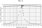
- the black-dot plot indicates the laser beam irradiation efficiency of the channel No. 1, and the blank-dot plot indicates that of the channel No. 6.
- the channel No. 6 is at a position spaced apart from the channel No. 1 by 1 mm, and was selected as an index for determining the availability of the side-entry laser-beam irradiation.
- the difference between the refractive index of the droplet nd and the refractive index of oil no, or nd - no may be such that -0.02 ⁇ nd - no ⁇ 0.05. It was also learned that, in order to obtain the laser beam irradiation efficiency of 0.4 or more for enabling higher-sensitivity fluorescence detection, the refractive index of the droplet nd may be such that 1.47 ⁇ nd ⁇ 1.51. That is, it was learned that the difference between the refractive index of the droplet nd and the refractive index of oil no, or nd - no, may be such that -0.01 ⁇ nd - no ⁇ 0.03.
- the solid-dot plot indicates the laser beam irradiation efficiency of channel No. 1.
- the blank-dot plot indicates the laser beam irradiation efficiency of channel No. 6. It was learned that the laser beam irradiation efficiency of channel No.
- the refractive index of oil no may be such that 1.28 ⁇ no ⁇ 1.35.
- the difference between the refractive index of the droplet nd and the refractive index of oil no, or nd - no may be such that -0.02 ⁇ nd - no ⁇ 0.05. It was also learned that, in order to obtain the laser beam irradiation efficiency of 0.4 or more for enabling higher-sensitivity fluorescence detection, the refractive index of oil no may be such that 1.30 ⁇ no ⁇ 1.34. That is, it was learned that the difference between the refractive index of the droplet nd and the refractive index of oil no, or nd - no, may be such that -0.01 ⁇ nd - no ⁇ 0.03.
- Fig. 12 illustrates configuration examples of the microchip 1 using cross sectional views perpendicular to the long axes of the respective channels 2.
- the material of the microchip 1 is a transparent resin, glass and the like.
- the microchip 1 is generally fabricated by joining an upper substrate 17 having a flat surface to a lower substrate 18 having a plurality of grooves in a surface thereof at a bonding surface 19, and transforming the grooves into the channels 2.
- the cross sectional shape of the channels 2 becomes trapezoidal as illustrated in Fig. 12(b) , rather than square or rectangle as illustrated in Fig. 12(a) .
- the problem has been newly discovered that the laser beam 3 entering the side surface of the microchip 1 along the array plane is subjected to refraction in the same direction by the both right and left side surfaces of the respective channels 2, and deviates from the array plane as the laser beam 3 passes through the plurality of channels 2. More specifically, when the refractive index of the interior of the respective channels 2 (droplets or oil) is smaller than the refractive index of the microchip 1, the laser beam deviates on the lower side of the array plane, as illustrated in Fig. 12(b) . Conversely, when the refractive index of the interior of the respective channels 2 (droplets or oil) is greater than the refractive index of the microchip 1, the laser beam deviates on the upper side of the array plane. In either case, even if the refractive indexes of droplets and oil are matched, simultaneous irradiation of the plurality of channels 2 becomes difficult.
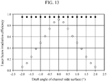
- Fig. 13 illustrates the results of an investigation of laser beam irradiation efficiency when the draft angle was increased from the condition of Fig. 12(a) (draft angle zero degree). It should be noted that while the refractive index of the material of the microchip remained 1.53, the refractive indexes of the droplets and oil in the channels were each 1.33 instead of 1.48.
- the draft angle was defined as the angle obtained by subtracting 90 degrees from the angle formed by the array plane of the plurality of channels and the side surfaces of the respective channels, or the angle obtained by subtracting 90 degrees from the angle formed by the bottom side and lateral sides of the quadrangle of the channel cross section (base angle of the trapezoid).
- the solid-dot plot indicates the laser beam irradiation efficiency for channel No.
- the blank-dot plot indicates the laser beam irradiation efficiency for channel No. 6.
- the laser beam irradiation efficiency is the same as the laser beam irradiation efficiency when the refractive index of oil is 1.33 in Fig. 11 .
- the laser beam irradiation efficiency is right-left symmetric with respect to the draft angle of zero degree, and decreases as the draft angle is increased or decreased. It was learned that in order to obtain the laser beam irradiation efficiency of 0.2 or more necessary for obtaining a practical level of fluorescence detection sensitivity, the draft angle may be not more than ⁇ 1.5 degrees. It was also learned that in order to obtain the laser beam irradiation efficiency of 0.4 or more for enabling higher-sensitivity fluorescence detection, the draft angle may be not more than ⁇ 1.0 degree.
- the microchip 1 As a means for fabricating the microchip 1 illustrated in Fig. 12(a) , it may be contemplated to process the grooves in the lower substrate by cutting. However, such processing method is not suitable for mass production, and has the disadvantage of high manufacturing cost. Accordingly, as illustrated in Fig. 12(c) , a method has been devised by which the microchip 1 is configured from a plurality of intermediate substrates 20 in addition to the upper substrate 17 and the lower substrate 18, and joined at bonding surfaces 19, 21.
- the plurality of intermediate substrates 20 are respectively separate substrates that constitute the walls between adjacent two channels 2, and the walls between the channels 2 at both ends and both side surfaces of the microchip 1. Accordingly, before the joining by the bonding, it becomes relatively easy to bring the side surfaces of the respective intermediate substrates 20 closer to 90 degrees with respect to the array plane of the channels, and to polish the side surfaces of the respective intermediate substrates 20 to a mirror finish.
- the microchip 1 of glass material was fabricated according to the configuration of Fig. 12(c) .
- Fifteen channels 2 were arrayed on the same plane at the intervals of 200 ⁇ m in the laser beam irradiation position.
- the cross section of the respective channels 2 was a square with sides of 50 ⁇ m, and the angle of both side surfaces with respect to the array plane was kept at 90 ⁇ 0.5 degrees.
- PCR was performed, and, with the droplets being lined up single file, the droplets and oil for each sample were introduced into each of the 15 channels 2 and caused to flow by vacuum aspiration.
- the droplet size was 40 ⁇ m in diameter assuming that the droplet was spherical.
- sucrose in the droplets, 25% of sucrose was included together with a PCR reagent to adjust the refractive index to be matched with the refractive index of oil at 1.375.
- a PCR reagent to adjust the refractive index to be matched with the refractive index of oil at 1.375.
- mixing of sucrose in PCR solution is often done, and is believed to not hinder PCR.
- the amount of genetic mutation at one location or three locations in genomes included in each sample is absolutely quantitated.
- amplification by PCR was caused when a genetic mutation of interest existed in each droplet, and fluorescence with a main wavelength band of from 560 to 580 nm was emitted by laser beam irradiation.
- PCR was performed with respect to the three locations in parallel, amplification was caused independently when the respective genetic mutation existed, and different fluorescence was emitted. That is, the amplification at the three locations can be identified with three colors of fluorescence.
- the three colors of fluorescence had main wavelength bands of from 520 to 540 nm, from 560 to 580 nm, and from 600 to 620 nm.
- the droplets that do not include any genetic mutations produce relatively weak fluorescence or scattered light. Accordingly, it is possible to count the number of the droplets by detecting and discriminating them from the droplets that emit relatively strong fluorescence by the amplification. In order to detect the droplets with higher sensitivity, a difference in Raman scattered light due to laser beam irradiation of the oil and droplets in the three colors of wavelength bands may be utilized. Because the intensity ratios of Raman scattered light in the three colors of wavelength bands differ from those of the respective fluorescence, it is possible to accurately discriminate Raman scattered light from fluorescence.
- Fig. 14(a) is a schematic frontal view illustrating an example of the microchip 1 having a multi-channel array. For sake of simplicity, only four channels 2 are drawn. At both ends of the respective channels 2, entries 13 and exits 14 are provided, and the flow of droplets and oil was in the direction from the entries 13 to the exits 14.
- the microchip 1 constitutes a flow path section of a light detection device, and a line of flow is formed in each of the channels 2.
- the laser beam 3 emitted from the laser light source 5 is introduced via a side surface of the microchip 1 along the array plane of the channels 2 vertically to the longitudinal direction of the respective channels.
- the channels 2 have an array interval that is smaller around the laser-beam irradiation position and that is greater around the entries 13 and exits 14 at the ends.
- the laser light source 5 and the area of the microchip 1 that is irradiated with the laser beam 3 constitute a laser beam irradiation section.
- Fig. 14(b) is a schematic diagram of a configuration example in which, in order to improve detection accuracy by increasing the intervals of droplets flowing in the respective channels 2 around the laser beam irradiation position, the respective channels 2 are provided with a mechanism for adding oil between the entries 13 and the laser beam irradiation position. For each channel 2, oil is introduced from oil entries 15 at two locations into the respective channels 2 from two directions. The added oil is discharged via the exits 14 together with the droplets and oil introduced via the entries 13.
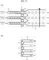
- Fig. 15 schematically illustrates the overall configuration of the light detection device, and illustrates a configuration example of the laser beam irradiation section and a light detection section of the microchip 1.
- the light detection section the light emitted separately from the droplets in each line of flow due to the irradiation of the laser beam 3 is detected from the vertical direction with respect to the array plane.
- Fig. 15(a) is a view from a direction parallel with the long axes of the respective channels 2.
- Fig. 15(b) is a view from a direction perpendicular to the long axes of the respective channels 2.
- the droplets flowing in the respective channels 2 cross the laser beam 3, they are excited by the laser beam 3 and emit fluorescence according to PCR. That is, if the droplets include target genetic mutations, the droplets emit strong fluorescence; if not, the droplets only emit weak fluorescence.
- the fluorescence emitted from the respective channels 2 is detected by a fluorescence detection optical system.
- the fluorescence emitted from the respective channels 2 is turned into a parallel light bundle by a common collection lens 6, passes through a filter and diffraction grating 7, and imaged by an imaging lens 8 on a sensor plane of a sensor 9.
- the filter is provided to block the wavelengths of the laser beam 3 that would provide background light in fluorescence detection, and the diffraction grating as a wavelength dispersion element is provided to disperse the wavelengths of the fluorescence for multicolor detection.
- the diffraction grating in the filter and diffraction grating 7 may be omitted.
- Fig. 15(a) because the fluorescence emitted from different channels 2 is imaged at different positions on the sensor plane of the sensor 9, the fluorescence from different channels 2 can be independently detected.
- Fig. 15(b) the fluorescence emitted from a light emitting point 11 of each channel 2 is imaged after being wavelength-dispersed in the longitudinal direction of the respective channel 2, i.e., in a direction perpendicular to the optical axis of the laser beam 3, thus allowing the independent detection of the fluorescence of each wavelength.
- the collection lens 6 and the imaging lens 8 each may comprise a combination lens in order to reduce the influence of aberration and increase imaging performance. It may be effective to use commercially available camera lenses for single-lens reflex cameras, or objective lenses for microscopes.
- the collection lens 6 and the imaging lens 8 may be lenses of the same or different specifications.
- the fluorescence emitted from a plurality of capillaries is detected by similar fluorescence detection optical systems where a two-dimensional CCD sensor or CMOS sensor may be used as the sensor 9.
- a two-dimensional CCD sensor or CMOS sensor may be used as the sensor 9.
- a similar two-dimensional sensor may be used in the present example; however, as the flow speed of droplets increases, the imaging speed may fail to catch up, resulting in an increase in the number of droplets that cannot be detected. Accordingly, in the present example, instead of a two-dimensional sensor, a plurality of 1-dimensional line sensors 12 are disposed.
- sensor elements are arrayed two-dimensionally in a row direction and a column direction, where data acquisition including AD conversion is performed with respect to the sensor elements arrayed 1-dimensionally in the row direction at once. This step is successively shifted in the column direction to perform data acquisition for all of the sensor elements. Accordingly, compared with the data acquisition time for a 1-dimensional sensor, the data acquisition time for a two-dimensional sensor may be multiplied by the number of columns, i.e., by a factor of several thousands, independently from the exposure time. In the present example, as illustrated in Fig.
- three line sensors 12 are disposed for respectively detecting the three wavelength bands of 520 to 540 nm, 560 to 580 nm, and 600 to 620 nm.
- the example is arranged so that it is possible not only to perform data acquisition including AD conversion with respect to the respective sensor elements in each line sensor at once, but also to perform the data acquisition with respect to the respective line sensors in parallel.
- the configuration enables high speed data acquisition at 100 kHz with respect to all of the sensor elements constituting each of the line sensors 12. In this way, it becomes possible to perform multicolor detection for all of the droplets that flow in the respective channels 2 at 1 kHz, that is, the droplets passing through the laser beam 3 at the rate of as many as one thousand per second.
- the senor 9 in Fig. 15 it may also be effective to use a photomultiplier array 32 illustrated in Fig. 17 . In this way, the fluorescence emitted from the plurality of channels 2 can be subjected to multicolor detection simultaneously and at higher speed and sensitivity.
- Fig. 16(a) is a schematic diagram of a modification of the configuration of the laser irradiation and fluorescence detection sections of the microchip 1 illustrated in Fig. 15 .
- a laser beam laterally enters multiple channels arrayed in the microchip, and the light emitted from the multiple channels is detected using respectively different optical fibers and different photomultipliers.
- the photomultipliers 30 as light detectors instead of the line sensors 12, fluorescence detection can be performed at higher speed and higher sensitivity than is possible with the light detection device illustrated in Fig. 15 . Because the size of the photomultipliers 30 is generally greater than the line sensors 12, adopting an optical system similar to that of Fig. 15(b) is difficult.
- the light emitting points and the light detectors are connected by optical fibers 28.
- the light emitted from the respective channels 2 by the irradiation of the laser beam 3 is collected by individual collection lenses 27, and caused to enter one end of the optical fibers 28.
- the emitted light exiting the other end of the optical fibers 28 is again respectively collected by the individual collection lenses 29, caused to enter the photomultipliers 30 via a filter, and detected at high speed and with high sensitivity.
- the present configuration does not include a spectroscopic means and is therefore effective when performing single color detection, as in the case of genetic mutation quantitation at one location.
- each microchip 1 may be provided with a guide so as to facilitate the adjustment of the relative positions of the individual collection lenses 27 and the respective channels 2.
- Fig. 16(b) is a schematic diagram of a light detection device which is a further modification of Fig. 16(a) configured to enable multicolor detection of exit light from the respective optical fibers.
- the individual collection lenses 27 are integrated not with the optical fibers 28 but with the microchip 1, and the relative positions of the respective channels 2 and the individual collection lenses 27 are adjusted in advance.
- the structure can be easily obtained by injection molding and the like in the process of fabricating the microchip 1.
- the relative positions between the respective channels 2 and the individual collection lenses 27 with higher accuracy are required than the relative positions between the individual collection lenses 27 and the one end of the optical fibers 28. Accordingly, the configuration of Fig. 16(b) facilitates the overall position adjustment.
- Fig. 16(b) facilitates the overall position adjustment.
- the emitted light exiting the other end of each of the optical fibers 28 is collected by the individual collection lenses 29, divided by dichroic mirrors 31, and then respectively detected by the different photomultipliers 30.
- the emitted light exiting the other end of each of the optical fibers 28 is collected by the individual collection lenses 29, divided by dichroic mirrors 31, and then respectively detected by the different photomultipliers 30.
- two color detection is performed with respect to each emitted light. It goes without saying, however, that multicolor detection for three or more colors can be handled by similar configurations.
- Fig. 17 is a schematic diagram of an example of a light detection device in which the exit light from the plurality of optical fibers 28 is respectively detected not by the different photomultipliers 30 as in Fig. 16 , but by a single photomultiplier array 32 comprising a plurality of photomultipliers integrated together.
- the 8-channel linear array PMT H9530
- eight detection areas measuring 2.0 ⁇ 2.5 mm are arrayed at intervals of 2.8 mm.
- the sensor is capable of detecting light entering each detection area respectively independently at the sensitivity and speed comparable to those of the 1-channel photomultipliers 30.
- the light exit ends of the respective optical fibers 28 are arrayed at intervals of 2.8 mm.
- the exit light from the respective optical fibers 28 is collected by the individual collection lenses 29, caused to enter the different detection areas, and subjected to high sensitivity detection at 1 MHz.
- the 1 MHz detected data are subjected to integrating processing by the data processing unit 10 for further sensitivity improvement.
- the present configuration does not include a spectroscopic means and is therefore effective for performing single color detection, as in the case of genetic mutation quantitation at one location.
- Fig. 18 is a schematic diagram of an exemplary development of the configuration of Fig. 17 for multicolor detection.
- the configuration from the laser light source 5 to the individual collection lenses 29 is the same as that of Fig. 17.
- Fig. 18 is a view from the right side of Fig. 17 , and only shows the light exit end of the optical fiber 28 arrayed at the right-most side of Fig. 17 .
- the exit light from each of the optical fibers 28 is turned into a parallel light bundle by the individual collection lenses 29, and then divided by four types of dichroic mirrors 31 into four parallel light bundles of four colors proceeding in the same direction.
- each of the dichroic mirrors 31 may comprise a single common member for each of the optical fibers 28.
- the photomultiplier array 32 may be the 64-channel, two-dimensional array PMT (H7546) available from Hamamatsu Photonics K.K. In this sensor, a total of 64 detection areas each measuring 2.0 ⁇ 2.0 mm are disposed in an 8 ⁇ 8 array at intervals of 2.3 mm. Of the two-dimensional array, one dimension is set for the direction in which the plurality of optical fibers 28 are arrayed, and the other dimension is set for the direction in which the parallel light bundles are divided by the dichroic mirrors 31, whereby the fluorescence emitted from the plurality of channels 2 can be independently subjected to four color, high sensitivity detection at 1 MHz.
- PMT Hamamatsu Photonics K.K
- each divided parallel light bundle derived from the light emitted from the plurality of channels 2 is not necessarily required to enter one detection area, and may instead straddle a plurality of detection areas. In that case, it is effective to perform integrating processing in the data processing unit 10 on the detection signals from the plurality of detection areas into which the parallel light bundle has entered.
- Fig. 19 is a schematic diagram of a modification of Fig. 18 , illustrating a configuration example of a light detection device in which the order of the optical fibers 28 and the dichroic mirrors 31 in Fig. 18 is reversed.
- Fig. 19 similarly to Fig. 18 , is a view from the direction of the axis of laser beam irradiation, and includes the microchip 1.
- the fluorescence emitted from the light emitting point 11 that is the laser beam irradiation position of each of the respective channels 2 is collected by the individual collection lenses 27, divided by the four types of dichroic mirrors 31 into four parallel light bundles of four colors proceeding in the same direction, and each caused to enter a different one end of the optical fibers 28.
- each of the optical fibers 28 is again collected by the individual collection lenses 29, caused to enter the respective detection areas of the photomultiplier array 32, and detected at high speed and with high sensitivity.
- the number of necessary optical fibers 28 is increased by a factor of four compared with Fig. 18 .
- the configuration provides the advantage in that the alignment of the light exit end of the optical fibers 28 and the detection areas of the photomultiplier array 32 is facilitated.
- Fig. 20 is a schematic diagram of a configuration example of a light detection device in which, in order to reduce device cost compared with Fig. 16 , the light emitted from the plurality of channels 2 is independently detected by a single photomultiplier 30.
- the plurality of optical fibers 28 are consolidated into a single consolidated optical fiber 34 via an optical fiber switch 33, and the exit light from the consolidated optical fiber 34 is collected by an individual collection lens 29, and then detected by a photomultiplier 30.
- the optical fiber switch 33 has the function of optically connecting only one of the plurality of optical fibers 28 to the consolidated optical fiber 34, and allowing the transmission light in the optical fiber 28 to be transmitted to the consolidated optical fiber 34.
- the plurality of optical fibers 28 are connected in sequence repeatedly at intervals of 0.1 millisecond (10 kHz), thereby allowing the emitted light from the plurality of channels 2 to be detected by the single photomultipliers 30 by time division.
- Examples of the mechanism of the optical fiber switch 33 include a scheme in which the relative positions of the plurality of optical fibers 28 and the single consolidated optical fiber 34 are mechanically slid to switch their mutual optical connections, and a scheme in which the optical fiber 28 that connects the consolidated optical fiber 34 is switched by mechanically controlling the angle of micromirrors that respectively reflect the exit light from the plurality of optical fibers 28.
- a liquid crystal shutter array is used which is capable of performing stable switching at higher speed.
- the exit light from the respective optical fibers 28 is turned into parallel light bundles by individual collection lens, and the parallel light bundles are respectively caused to enter different optical fibers via individual liquid crystal shutters.
- the optical fibers are consolidated into the consolidated optical fiber 34 in a subsequent stage.
- the liquid crystal shutters are able to control their opening and closing by electrical control at high speed, so that the optical connection between the respective optical fibers 28 and the consolidated optical fiber 34 can be easily switched at high speed.
- the optical fiber switch does not require a mechanical operation, and therefore provides high stability.
- the switching of the optical fibers 28 by the optical fiber switch 33 and signals detected by the photomultipliers 30 are associated with each other in the data processing unit 10. Accordingly, the light emitted from the respective channels 2 can be independently detected at high speed and with high sensitivity.
- the object of interest has been the light emitted by laser irradiation of the plurality of channels 2 configured in the microchip 1.
- the light detection device is not limited to such object of interest, and may provide similar effects with respect to an arbitrary object in which a plurality of light emitting points are arrayed.
- the light detection device is specifically concerned with the case in which droplets and oil are flowed in respective channels, where fluorescence is emitted from the droplets by laser irradiation.
- the uses of the light detection device are not limited to such cases. Similar effects can be obtained when the light emitted from a plurality of light emitting points is detected at high speed and with high sensitivity, particularly in the case of multicolor detection.
- a plurality of lines of flow are configured not inside a microchip but in the inner spaces of a plurality of capillaries. That is, in the present example, a flow path section of the light detection device is configured by a plurality of capillaries aligned and arrayed on an array plane.
- Fig. 21 is a schematic diagram of the light detection device according to the present example.
- Fig. 21 illustrates a configuration example of the laser beam irradiation section and the fluorescence detection section for a plurality of capillaries 16, and corresponds to Fig. 15(a) of Example 1. Unless specifically noted, the configuration and method are similar to those of Example 1.
- Twenty-four capillaries 16 with a refractive index of 1.46 and made of quartz glass are arrayed in the air on the array plane.
- lines of flow are formed in which a plurality of droplets dispersed in oil are moved along a linear flow.
- the capillaries 16 are denoted by capillary numbers No. 1 to No. 24 from the left side in sequence.
- the capillaries had an outer diameter of 100 to 323 ⁇ m, an inner diameter of 10 to 50 ⁇ m, and an array interval in the laser beam irradiation position of 150 ⁇ m or 370 ⁇ m. In the above ranges, effective conditions for side-entry laser-beam irradiation were considered.
- the laser beam irradiation section is configured from the laser light source 5 and an area in which the plurality of capillaries 16 are irradiated with the laser beam 3.
- the light detection section is disposed in a vertical direction with respect to the array plane of the capillaries.
- a total volume of 20 microliter was divided into about 600 thousand droplets with a volume of 34 picoliters in oil, and then PCR was performed.
- the droplets and oil for each sample were introduced into each of the 24 capillaries 16 with the droplets being lined up single file by vacuum aspiration, and caused to flow.
- the droplet size was 40 ⁇ m in diameter assuming that the droplet was spherical.
- the device was simplified by adopting a configuration in which one ends of the 24 capillaries were directly and respectively inserted into the 24 kinds of sample solutions after PCR, where suctioning was performed from the other ends.
- the difference between the refractive index of the droplet nd and the refractive index of oil no, or nd - no needs to be - 0.02 ⁇ nd - no ⁇ 0.05 and preferably -0.01 ⁇ nd - no ⁇ 0.03.
- the oil used was Fluorinert FC-43 from 3M with a refractive index of 1.29 into which trace amounts of high refractive index substance was mixed to adjust the refractive index to 1.33.
- a standard PCR solution with a refractive index of 1.33 was used to match the refractive index of oil.
- 1% EA-surfactant from RainDance Technologies was mixed in the oil.
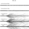
- Fig. 22 , Fig. 25 , and Fig. 28 illustrate the results of the laser-beam ray-tracing simulations, where the capillaries are drawn with outlines indicating the outer diameter of each capillary for sake of clarity.
- Fig. 22(a) illustrates the result in the case of an outer diameter of 323 ⁇ m, an inner diameter of 50 ⁇ m, and an array interval of 370 ⁇ m, where the capillaries were internally filled with a solution with a refractive index of 1.41.
- the side-entry laser beam had a diameter of 50 ⁇ m.
- the conditions are equivalent to those of commercially available capillary DNA sequencers, and the multiple-laser-beam-focusing technique is functioning to enable the laterally entering laser beam to irradiate and penetrate through all of the capillaries in a skewering manner.
- the result shown is that in the case of the side-entry laser beam entered from the left side of the capillary array.
- the result can extrapolate a result in a case where the laser beam is divided into two beams each with 50% laser beam intensity, and the two beams entered from both the right and the left sides of the capillary array. Therefore, the laser beam irradiation efficiency of each capillary, when the side-entry laser-beam irradiation entered from both sides of the capillary array, is indicated by a blank-triangle plot in Fig. 23 .
- the laser beam irradiation efficiency of the 24 capillaries has an average value of 47% and a CV value of 11%, indicating extremely high efficiency and uniformity.
- the laser beam irradiation efficiency becomes minimum at 42% for the capillary with capillary number 12 or 13 arrayed at the center.
- the capillaries have the laser beam irradiation efficiency of not less than 0.4, it is possible to perform fluorescence detection with high sensitivity higher than or equal to that of commercially available capillary DNA sequencers. It is also empirically known that a practical level of fluorescence detection sensitivity can be obtained when the laser beam irradiation efficiency of the capillaries is not less than 0.2.
- Fig. 22(b) illustrates the result in the case where, from the conditions of Fig. 22(a) , the refractive index of the solution in the capillaries was reduced from 1.41 to 1.33 according to the conditions of the present example. Because the internal concave lens action of each capillary became stronger than the convex lens action of the glass portion of each capillary, the multiple-laser-beam-focusing technique failed to function, resulting in a significant divergence of the laser beam from the capillary array plane.
- the solid-triangle plot determined by a method similar to that for the blank-triangle plot, indicates the laser beam irradiation efficiency in case of Fig. 22(b) .
- the laser beam irradiation efficiency is sharply decreased with an average value of 17% and a CV value of 78%, and both efficiency and uniformity are greatly degraded, indicating that the conditions are not suitable for the simultaneous irradiation of the 24 capillaries.
- the outer diameter of the capillaries was decreased to 300 ⁇ m, 250 ⁇ m, 200 ⁇ m, and 150 ⁇ m as illustrated in Fig. 22(c) to (f) , in an attempt to increase the convex lens action of the glass portion of each capillary.
- the other conditions were the same as those of Fig. 22(b) .
- the multiple-laser-beam-focusing technique began to function as the outer diameter was decreased.
- the blank-square plot, the solid-square plot, the blank-dot plot, and the solid-dot plot respectively indicate the results of similar determination of laser beam irradiation efficiency with respect to the outer diameter of 300 ⁇ m, 250 ⁇ m, 200 ⁇ m, and 150 ⁇ m. From Fig. 23 , it became clear that when the outer diameter of the capillaries is less than 250 ⁇ m, functionality of the multiple-laser-beam-focusing technique is enhanced sharply. That is, the emitted fluorescence from a number of droplets flowing in the 24 capillaries can be simultaneously subjected to multicolor detection at high speed and with high sensitivity.
- Fig. 24 illustrates the results of a more detailed analysis of the foregoing, and indicates the relationship between the outer diameter of the capillaries and the laser beam irradiation efficiency with respect to the capillary with capillary number 12. It became clear that as the outer diameter of the capillary is decreased from 250 ⁇ m to 200 ⁇ m, multiple-laser-beam-focusing technique begins to function, and the laser beam irradiation efficiency is sharply improved. It was learned that in order to obtain the laser beam irradiation efficiency of 0.2 or more necessary for obtaining a practical level of fluorescence detection sensitivity, the outer diameter of the capillary may be not more than 227 ⁇ m.
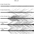
- Fig. 25 illustrates the results of similar laser-beam ray-tracing simulations of side-entry laser-beam irradiation with respect to the aerial array of 24 capillaries with an outer diameter 150 ⁇ m, an inner diameter of 10 ⁇ m to 50 ⁇ m, and an array interval of 150 ⁇ m, where the capillaries were internally filled with a solution with a refractive index of 1.33.
- Fig. 25(a) indicates the result in the case of the inner diameter of 50 ⁇ m, where the only difference from Fig. 22(f) was that the array interval was reduced from 370 ⁇ m to 150 ⁇ m.
- the solid-dot plot indicates the result of similar computation of the laser beam irradiation efficiency in this case. The average value was 46% and the CV value was 12%, which are equivalent to those of the solid-dot plot of Fig. 23 , indicating that both efficiency and uniformity were extremely high.
- Fig. 25(b), (c), (d), and (e) respectively illustrates the results in the case where, from the conditions of Fig. 25(a) , the inner diameter was reduced to 40 ⁇ m, 30 ⁇ m, 20 ⁇ m, and 10 ⁇ m. As the inner diameter was decreased, this time the internal concave lens action of each capillary became strong, the multiple-laser-beam-focusing technique again failed to function, and the divergence of the laser beam from the capillary array plane became significant.
- Fig. 25(b), (c), (d), and (e) respectively illustrates the results in the case where, from the conditions of Fig. 25(a) , the inner diameter was reduced to 40 ⁇ m, 30 ⁇ m, 20 ⁇ m, and 10 ⁇ m. As the inner diameter was decreased, this time the internal concave lens action of each capillary became strong, the multiple-laser-beam-focusing technique again failed to function, and the divergence of the laser beam from the capillary array plane became
- the blank-dot plot, the solid-square plot, the blank-square plot, and the solid-triangle plot respectively indicate the results of similar determination of the laser beam irradiation efficiency with respect to the inner diameters of 40 ⁇ m, 30 ⁇ m, 20 ⁇ m, and 10 ⁇ m. From Fig. 26 , it became clear that by making the inner diameter of the respective capillaries greater than 30 ⁇ m, the multiple-laser-beam-focusing technique can be caused to function. That is, the fluorescence emitted from a number of droplets flowing in the 24 capillaries can be simultaneously subjected to multicolor detection at high speed and with high sensitivity.
- Fig. 27 illustrates the results of a more detailed analysis of the foregoing, and indicates the relationship between the inner diameter of the capillary and the laser beam irradiation efficiency with respect to the capillary with capillary number 12. It became clear that as the inner diameter of the capillary is increased from 30 ⁇ m to 40 ⁇ m, multiple-laser-beam focusing began to function, and the laser beam irradiation efficiency is sharply improved. It was learned that in order to obtain the laser beam irradiation efficiency of 0.2 or more necessary for obtaining a practical level of fluorescence detection sensitivity, the inner diameter of the capillary may be not less than 34 ⁇ m.
- Fig. 28 illustrates the results of similar laser-beam ray-tracing simulations of side-entry laser-beam irradiation with respect to the aerial array of 24 capillaries with an outer diameter of 100 ⁇ m, an inner diameter of 10 ⁇ m to 50 ⁇ m, an array interval of 150 ⁇ m, where the capillaries were internally filled with a solution with a refractive index of 1.33.
- the outer diameter of the capillaries was further reduced from the case of Fig. 25 in an attempt to again enhance the convex lens action of the glass portion of each capillary.
- Fig. 28(a) illustrates the result in the case of the inner diameter of 50 ⁇ m, the only difference from Fig.
- the solid-dot plot indicates the result of similar computation of the laser beam irradiation efficiency in this case.
- the average value was 46% and the CV value was 12%, which are equivalent to those of the solid-dot plot of Fig. 26 , indicating that both efficiency and uniformity were extremely high.
- Fig. 28(b), (c), (d), and (e) respectively illustrates the results in the case where, from the conditions of Fig. 28(a) , the inner diameter was reduced to 40 ⁇ m, 30 ⁇ m, 20 ⁇ m, and 10 ⁇ m. As the inner diameter is reduced, the internal concave lens action of each capillary is enhanced, the multiple-laser-beam-focusing technique again fails to function, and the divergence of the laser beam from the capillary array plane became significant.
- Fig. 28(b), (c), (d), and (e) respectively illustrates the results in the case where, from the conditions of Fig. 28(a) , the inner diameter was reduced to 40 ⁇ m, 30 ⁇ m, 20 ⁇ m, and 10 ⁇ m. As the inner diameter is reduced, the internal concave lens action of each capillary is enhanced, the multiple-laser-beam-focusing technique again fails to function, and the divergence of the laser beam from the capillary array plane became significant.
- the blank-dot plot, the solid-square plot, the blank-square plot, and the solid-triangle plot respectively indicate the results of similar determination of the laser beam irradiation efficiency with respect to the inner diameters of 40 ⁇ m, 30 ⁇ m, 20 ⁇ m, and 10 ⁇ m. From Fig. 29 , it became clear that by making the inner diameter of the respective capillaries greater than 20 ⁇ m, the multiple-laser-beam-focusing technique can be caused to function. That is, the fluorescence emitted from a number of droplets flowing in the 24 capillaries can be simultaneously subjected to multicolor detection at high speed and with high sensitivity.
- Fig. 30 illustrates the result of a more detailed analysis of the foregoing, and indicates the relationship between the inner diameter of the capillary and the laser beam irradiation efficiency of capillary number 12. It became clear that as the inner diameter of the capillary is increased from 20 ⁇ m to 30 ⁇ m, the multiple-laser-beam focusing begins to function, and the laser beam irradiation efficiency is sharply improved. It was learned that in order to obtain the laser beam irradiation efficiency of 0.2 or more necessary for obtaining a practical level of fluorescence detection sensitivity, the inner diameter of the capillary may be not less than 25 ⁇ m. Thus, the threshold value of the inner diameter for causing the multiple-laser-beam-focusing technique to function is reduced from the case of Fig. 27 . This is because the convex lens action has been enhanced by the reduction in outer diameter.
- the results of Fig. 22 to Fig. 30 indicate that the multiple-laser-beam-focusing technique functions when the convex lens action of the glass portion of each capillary is stronger than the internal concave lens action of each capillary.
- the convex lens action becomes more enhanced as the outer diameter becomes smaller, while the concave lens action becomes more enhanced as the inner diameter becomes smaller.
- the multiple-laser-beam-focusing technique can be caused to function by making the ratio of outer diameter/inner diameter smaller than a constant value.
- the diameter of the droplets handled in the present example is 40 ⁇ m assuming that the droplet is spherical.
- channel short-axis width (capillary inner diameter) > droplet diameter.
- the above condition would be satisfied by using a capillary with an inner diameter of 50 ⁇ m, for example, and it would become possible to perform satisfactory fluorescence detection from the droplets. Meanwhile, a new effect may be obtained when channel short-axis width (capillary inner diameter) ⁇ droplet diameter.
- the droplets are placed in a state of being crushed in the capillary, whereby the curvature of the interface of the droplets becomes smaller than the curvature when the droplets are spheres.
- the lens action of the droplets with respect to the laser beam becomes smaller, which is advantageous in detecting the droplets flowing in a plurality of channels or capillaries.
- a plurality of channels are configured in the same microchip.
- the microchip comprised a cycloolefin polymer (COP) with a refractive index of 1.53.
- COP cycloolefin polymer
- PCR was performed.
- the droplets and oil of each sample were introduced into each of 24 channels by vacuum aspiration with the droplets being lined up single file, and then caused to flow.
- the droplet size was 20 ⁇ m in diameter assuming that the droplet was spherical.
- the difference between the refractive index of the droplet nd and the refractive index of oil no, or nd - no needs to be -0.02 ⁇ nd - no ⁇ 0.05 and preferably -0.01 ⁇ nd - no ⁇ 0.03.
- the oil used was Perfluoro-phenanthrene Aqsia from Bausch & Lomb with a refractive index of 1.33.
- a standard PCR solution with a refractive index of 1.33 was used to match the refractive index of oil.
- 1% Pico-Surf 1 surfactant from Dolomite Microfluidics was mixed in oil.
- a number of droplets 4 are lined up single file in a channel 22 and caused to flow therein.
- oil is added into the channel so as to increase the intervals of the droplets as they flow into a wider channel 2.
- the channel 2 is irradiated with a laser beam 3 so as to irradiate the individual droplets 4 in sequence, and the fluorescence emitted from the individual droplets is measured in sequence.
- a number of droplets are lined up single file at smaller intervals.
- a number of droplets in the channel 2 are arrayed at greater intervals while being lined up single file.
- a channel 24 is present at the intermediate position between the channels 22 and 23 and the channel 2.
- the short-axis width of the channel 2 is greater than the short-axis width of the channel 22.
- the short-axis width of the channel 24 is equal to or smaller than the short-axis width of the channel 22.
- Fig. 32 and Fig. 33 each illustrate only three channels 22, this is for sake of simplicity, and the number of the channels is obviously not limited to three.
- Fig. 32(a) the configuration of Fig. 31 was parallelized in the same microchip, and side-entry laser-beam irradiation was applied to a plurality of channels 2.
- Fig. 32(b) is a cross sectional view perpendicular to the long axes of the respective channels 2 at the position irradiated with the laser beam 3 in Fig. 32(a) .
- the respective channels 2 similarly to Fig. 12(b) , the respective channels 2 have a trapezoidal cross section. Accordingly, the laser beam 3 as it passes through the side surfaces of the respective channels 2 is subjected to refraction in one direction, and deviates from the array plane of the channels 2. That is, it became clear that with the configuration of Fig. 32 , it is difficult to detect the droplets flowing in the plurality of channels 2 at once.
- the separating walls between the respective channels 2 at the laser beam irradiated position were removed, and the plurality of channels 2 were merged into a single merged channel 25.
- the width of the merged channel 25 in the central axis direction of the laser beam 3 is greater than the sum of the widths of the plurality of channels 22.
- Such configuration can be fabricated in the same microchip by means of injection molding and the like capable of mass production.
- the flow path section of the light detection device is configured of a microchip provided with the single merged channel 25.
- the merged channel 25 has retained therein a plurality of lines of flow in which a plurality of droplets dispersed in oil are moved along linear flows.
- the plurality of channels 22 By forming the plurality of channels 22 on the same plane, it becomes possible to arrange the plurality of lines of flow, which flow out of the respective channels 22 and which are formed in the merged channel 25, on the array plane.
- the plurality of lines of flow also include the laser beam irradiated portion in the merged channel 25.
- the problem of refraction of the laser beam 3 at the side surfaces of the respective channels 2 as discussed with reference to Fig. 32 can be avoided. Accordingly, it becomes possible for the laser beam 3 to travel in the merged channel 25 in the direction in which the plurality of lines of flow are arrayed, and to irradiate the droplets in the lines of flow flowing out of the respective channels 22 and 24 for fluorescence detection. However, the laser beam 3 may be refracted at the entry side surface of the merged channel 25. Thus, it is effective to cause the laser beam 3 to enter the merged channel 25 of the flow path section at an angle from being parallel to the array plane of the channels 22 so that the laser beam 3 is adjusted to be parallel to the array plane of the lines of flow in the merged channel 25.
- Fig. 34 is a schematic diagram of another configuration example of the microchip including the flow path section that is the merged channel.
- the width of the merged channel 25 in the central axis direction of the laser beam 3 is greater than the total of the widths of the respective channels 2 of Fig. 32 in the central axis direction of the laser beam 3.
- the channels 23 are connected from two directions perpendicular to the array plane of the respective channels 22, and oil is additionally supplied from the two directions.
- Fig. 34(a) is a view from the vertical direction with respect to the array plane of the channels 22.
- Fig. 34(b) is a view from the parallel direction with respect to the array plane.
- the configuration makes it possible to decrease the interval of the respective channels 22 compared with the case of Fig. 32 or Fig. 33 , and, as a result, to decrease the width of the merged channel 25 in the central axis direction of the laser beam 3 compared with the case of Fig. 33 .
- the respective channels 23 may not necessarily be perpendicular to the array plane of the respective channels 22, and may be inclined with respect to the array plane.
- the configuration only needs to be able to decrease the array interval of the respective channels 22.
- the width of the merged channel 25 in the central axis direction of the laser beam 3 is equal to the total of the widths of the respective channels 2 in the central axis direction of the laser beam 3 in Fig. 32 . That is, the amount of oil supplied from the channels 23 in Fig. 34 may be the same as in the case of Fig. 32 , and the laminar flow can be controlled as in Fig. 31 or Fig. 32 .
- Fig. 35 is a schematic diagram of another configuration example of the microchip including the merged channel, illustrating a modification of Fig. 34 .
- a plurality of lines of flow in which a plurality of droplets dispersed in oil are moved along linear flows are retained on the array plane in the merged channel 25.
- the channels 23 for additionally supplying oil approach the array plane of the respective channels 22 from one direction perpendicular thereto, and are bent at right angles at the array plane before being connected to the respective channels 22.
- Fig. 35(a) is a view from the vertical direction with respect to the array plane of the respective channels 22.
- Fig. 35(b) is a cross sectional view of the connected portions of the channels 23 and the channels 22 of Fig. 35(a) .
- oil can be added from a vertical direction with respect to the flows of the droplet 4 and oil in the respective channels 22, and at the same time, as in Fig. 34 , the array interval of the respective channels 22 can be decreased.
- Fig. 36 is a schematic diagram of a configuration example in which the array interval of the channel 2 is decreased by making the configuration of the channels 23 in Fig. 32 similar to Fig. 34 . That is, in the respective channels 22, oil is supplied from a vertical direction with respect to the array plane of the channels 22. As in Fig. 32 , the respective channels 2 are not merged and remain separated. In this configuration, the influence of refraction of the laser beam 3 by the side surfaces of the respective channels 2, as illustrated in Fig. 32(b) , cannot be avoided. However, because the array interval of the channel 2 is decreased, the number of the channels 2 that can be irradiated before the laser beam 3 deviates from the array plane can be increased.
- Fig. 37 is a schematic diagram of another configuration example of the microchip including the merged channel, illustrating a modification of Fig. 34 .
- the respective channels 22 comprise capillaries, and a plurality of lines of flow of the droplets 4 flowing out of the capillaries into the merged channel 25 are moved on the array plane.
- Fig. 37(a) is a view from a vertical direction with respect to the array plane of the channels 22.
- Fig. 37(b) is a view from a parallel direction with respect to the array plane.
- the droplets 4 and oil that flow in the respective channels 22 are discharged into the merged channel 25 from the ends of the respective channels 22, and form the lines of flow.
- oil supplied from a channel 26 encloses the peripheries of the respective channels 22 and flows in the same direction as the lines of flow.
- the droplets 4 being discharged from the respective channels 22 respectively form the lines of flow without becoming mixed, and move on the array plane while being lined up single file. That is, the droplets and oil are adjusted to form a laminar flow in the merged channel 25.
- a step of mixing one droplet of the specimen flowing in channel ⁇ and one droplet of the reagent flowing in channel ⁇ in channel ⁇ consolidating the channel ⁇ and channel ⁇ is continuously repeated for a number of droplets.
- the mixed droplet size is 50 ⁇ m in diameter.
- the reagent includes an enzyme that facilitate lysis of Escherichia coli, and a DNAzime sensor which emits fluorescence upon bonding of a decomposed product of Escherichia coli.
- a constant concentration of a fluorophore having an emission wavelength different from the above was mixed in the reagent. In this way, all of the droplets included the same kind and the same concentration of fluorophore, making it possible to digitally count all of the droplets.
- the fabricated group of droplets was transferred to a sample container and left to stand at room temperature for two hours for lysis of Escherichia coli and cause a reaction of the dissolved product and the DNAzime sensor. Thereafter, in a microchip which had the structure of the flow path section and the laser beam irradiation section illustrated in Fig. 34 and in which 100 channels 22 were parallelized, the group of droplets was divided into 100 parts and each introduced into each of the channels 22 and caused to flow.
- the laser beam 3 was entered from the side of the merged channel 25 to irradiate in parallel a plurality of droplets being discharged from the respective channels 22 and respectively forming lines of flow, and the emitted fluorescence was simultaneously detected from a vertical direction with respect to the array plane of the lines of flow.
- the droplets were detected at 1 kHz with respect to each of the channels 22, i.e., at the rate of 1000 droplets per second. If the detection is performed using only one channel, it would take eight hours or longer to detect all of the 30 million droplets. In the present example, 100 channels were used to perform parallel detection at the same detection speed, it was possible to detect the 30 million droplets in only five minutes.
Landscapes
- Chemical & Material Sciences (AREA)
- Health & Medical Sciences (AREA)
- General Health & Medical Sciences (AREA)
- Analytical Chemistry (AREA)
- Life Sciences & Earth Sciences (AREA)
- Chemical Kinetics & Catalysis (AREA)
- Biochemistry (AREA)
- Clinical Laboratory Science (AREA)
- Dispersion Chemistry (AREA)
- Immunology (AREA)
- Physics & Mathematics (AREA)
- General Physics & Mathematics (AREA)
- Pathology (AREA)
- Nuclear Medicine, Radiotherapy & Molecular Imaging (AREA)
- Hematology (AREA)
- Molecular Biology (AREA)
- Engineering & Computer Science (AREA)
- Biomedical Technology (AREA)
- Optics & Photonics (AREA)
- Investigating, Analyzing Materials By Fluorescence Or Luminescence (AREA)
- Investigating Or Analysing Materials By The Use Of Chemical Reactions (AREA)
- Apparatus Associated With Microorganisms And Enzymes (AREA)
- Measuring Or Testing Involving Enzymes Or Micro-Organisms (AREA)
- Investigating Or Analysing Materials By Optical Means (AREA)
Claims (19)
- Dispositif de détection de lumière comprenant :une huile incluant des gouttelettes (4) dispersées dans celle-ci ;une section (1) de chemin d'écoulement dans laquelle, lors de l'utilisation, une pluralité de lignes d'écoulement d'une pluralité desdites gouttelettes dispersées dans ladite huile le long d'un écoulement linéaire est maintenue sur un plan de réseau ;une section (5) d'irradiation de faisceau laser pour introduire un faisceau laser (3) dans une direction dans laquelle la pluralité de lignes d'écoulement dans la section de chemin d'écoulement sont mises en réseau pour irradier la pluralité de lignes d'écoulement ; etune section (6, 7, 8, 9) de détection de lumière pour détecter une lumière émise générée depuis la pluralité de lignes d'écoulement par l'irradiation du faisceau laser, depuis une direction verticale par rapport au plan de réseau,dans lequel l'huile a un indice de réfraction no et les gouttelettes ont un indice de réfraction nd, dans lequel la différence entre no et nd est telle que -0,02 ≤ nd - no ≤ 0,05.
- Dispositif de détection de lumière selon la revendication 1, dans lequel la différence entre l'indice de réfraction de l'huile no et l'indice de réfraction de la gouttelette nd est telle que -0,01 ≤ nd - no ≤ 0,03.
- Dispositif de détection de lumière selon la revendication 1, dans lequel :l'indice de réfraction de la gouttelette nd est nd = 1,33 ; etl'indice de réfraction de l'huile no est tel que 1,30 ≤ no ≤ 1,34.
- Dispositif de détection de lumière selon l'une quelconque des revendications 1 à 3, dans lequel :le dispositif comprend une micropuce (1) ayant un plan de réseau avec une pluralité de canaux (2) réunis en réseau sur celle-ci, la pluralité de lignes d'écoulement étant formées dans lesdits canaux ; etla pluralité de canaux ont une forme quadrangulaire en coupe transversale, et un angle formé par une surface latérale à travers laquelle le faisceau laser est fait passer et le plan de réseau est dans une plage de 90 ± 1,5 degrés.
- Dispositif de détection de lumière selon la revendication 4, dans lequel la pluralité de canaux (2) ont une largeur dans un sens d'axe optique du faisceau laser (3) d'irradiation qui est plus petite qu'un diamètre des gouttelettes lorsque les gouttelettes sont en une forme sphérique.
- Dispositif de détection de lumière selon l'une quelconque des revendications 1 à 3, dans lequel :le dispositif comprend une pluralité de capillaires (16) réunis en réseau dans l'air sur le plan de réseau, la pluralité de lignes d'écoulement étant respectivement formées dans lesdits capillaires ; etla pluralité de capillaires ont un diamètre extérieur de pas plus de 227 µm.
- Dispositif de détection de lumière selon l'une quelconque des revendications 1 à 3, dans lequel :le dispositif comprend une pluralité de capillaires (16) réunis en réseau dans l'air sur le plan de réseau, la pluralité de lignes d'écoulement étant respectivement formées dans lesdits capillaires ; etla pluralité de capillaires ont un diamètre intérieur de pas moins de 25 µm.
- Dispositif de détection de lumière selon l'une quelconque des revendications 1 à 3, dans lequel :le dispositif comprend une pluralité de capillaires (16) réunis en réseau dans l'air sur le plan de réseau, la pluralité de lignes d'écoulement étant respectivement formées dans lesdits capillaires ; etla pluralité de capillaires ont un rapport d'un diamètre extérieur sur un diamètre intérieur de ceux-ci de pas plus de 4,5.
- Dispositif de détection de lumière selon l'une quelconque des revendications 6 à 8, dans lequel la pluralité de capillaires (16) ont un diamètre intérieur qui est plus petit qu'un diamètre des gouttelettes (4) lorsque les gouttelettes sont en une forme sphérique.
- Dispositif de détection de lumière selon l'une quelconque des revendications 1 à 3, dans lequel :le dispositif comprend une micropuce avec un canal unique (25) prévu dans celle-ci, le canal unique étant configuré pour retenir la pluralité de lignes d'écoulement, la section d'irradiation de faisceau laser étant agencée pour irradier une partie de la pluralité de lignes d'écoulement dans ledit canal unique avec le faisceau laser (3) ;la micropuce comprend une première pluralité de canaux (22) réunis en réseau sur le plan de réseau en amont de la partie dans le canal unique irradiée avec le faisceau laser, la pluralité de lignes d'écoulement ayant une partie dans ladite première pluralité de canaux ; etle canal unique a une largeur dans un sens d'axe central du faisceau laser qui est plus grande qu'un total de largeurs de la première pluralité de canaux dans le même sens.
- Dispositif de détection de lumière selon la revendication 10, dans lequel le dispositif comprend en outre une deuxième pluralité de canaux (23) pour fournir de façon additionnelle de l'huile et dans lequel chaque canal de ladite première pluralité de canaux (22) a un canal de ladite deuxième pluralité de canaux (23) pour fournir de façon additionnelle de l'huile connecté à celui-ci
- Dispositif de détection de lumière selon la revendication 11, dans lequel les canaux (23) pour fournir de façon additionnelle de l'huile sont agencés pour fournir l'huile dans un sens incliné par rapport au plan de réseau.
- Dispositif de détection de lumière selon la revendication 11, dans lequel les canaux (23) pour fournir de façon additionnelle de l'huile sont agencés pour fournir l'huile dans un sens perpendiculaire au plan de réseau.
- Dispositif de détection de lumière selon la revendication 10, dans lequel le faisceau laser (3) introduit dans la section de chemin d'écoulement a un axe central qui est incliné par rapport au plan de réseau.
- Dispositif de détection de lumière selon l'une quelconque des revendications 1 à 3, dans lequel la section de détection de lumière inclut un ou une pluralité de capteurs (12) de lignes.
- Dispositif de détection de lumière selon l'une quelconque des revendications 1 à 3, dans lequel la section de détection de lumière inclut un élément (7) de dispersion de longueurs d'ondes et une pluralité de capteurs (12) de lignes, dans lequel différentes longueurs d'ondes de lumière émise sont respectivement détectées par différents capteurs de lignes.
- Dispositif de détection de lumière selon l'une quelconque des revendications 1 à 3, dans lequel la section de détection de lumière inclut une pluralité de photomultiplicateurs (30) ou un réseau unique (32) de photomultiplicateurs.
- Dispositif de détection de lumière selon la revendication 17, dans lequel le dispositif comprend des fibres optiques (28) et une lumière émise depuis les lignes d'écoulement respectives est détectée par la pluralité de photomultiplicateurs (30) ou le réseau unique (32) de photomultiplicateurs par l'intermédiaire de fibres optiques respectivement différentes parmi les fibres optiques.
- Dispositif de détection de lumière selon l'une quelconque des revendications 1 à 3, dans lequel les gouttelettes (4) respectives incluent un fluorophore du même type et d'une égale concentration
Applications Claiming Priority (1)
| Application Number | Priority Date | Filing Date | Title |
|---|---|---|---|
| PCT/JP2015/073507 WO2017033224A1 (fr) | 2015-08-21 | 2015-08-21 | Dispositif de détection de lumière |
Publications (3)
| Publication Number | Publication Date |
|---|---|
| EP3339841A1 EP3339841A1 (fr) | 2018-06-27 |
| EP3339841A4 EP3339841A4 (fr) | 2019-04-10 |
| EP3339841B1 true EP3339841B1 (fr) | 2021-11-10 |
Family
ID=58100042
Family Applications (1)
| Application Number | Title | Priority Date | Filing Date |
|---|---|---|---|
| EP15902196.3A Active EP3339841B1 (fr) | 2015-08-21 | 2015-08-21 | Dispositif de détection de lumière |
Country Status (5)
| Country | Link |
|---|---|
| US (1) | US10955342B2 (fr) |
| EP (1) | EP3339841B1 (fr) |
| JP (1) | JP6490817B2 (fr) |
| CN (1) | CN107850542B (fr) |
| WO (1) | WO2017033224A1 (fr) |
Families Citing this family (10)
| Publication number | Priority date | Publication date | Assignee | Title |
|---|---|---|---|---|
| EP3586104A4 (fr) * | 2017-02-27 | 2020-12-16 | Becton, Dickinson and Company | Systèmes de détection de lumière et leurs procédés d'utilisation |
| CN108865650B (zh) * | 2018-05-09 | 2023-02-14 | 中国科学院深圳先进技术研究院 | 微流控液滴散射光和荧光计数芯片 |
| CN114279970A (zh) * | 2020-04-23 | 2022-04-05 | 深圳市液芯科技有限公司 | 一种用于分析一种或多种待分析物的检测系统及其方法 |
| CN113984722B (zh) * | 2020-05-26 | 2025-09-26 | 深圳市液芯科技有限公司 | 液相芯片检测系统、分析一种或多种待分析物的方法 |
| CN112305154B (zh) * | 2020-10-16 | 2022-09-23 | 中石化石油工程技术服务有限公司 | 一种膨润土吸蓝量的自动分析检测仪及其检测方法 |
| JP7495999B2 (ja) * | 2020-12-18 | 2024-06-05 | 株式会社日立ハイテク | キャピラリアレイ |
| AU2022322756A1 (en) | 2021-08-04 | 2024-02-08 | Becton, Dickinson And Company | Light detection systems having first and second light receivers, and methods of use thereof |
| CN114100713B (zh) * | 2021-11-22 | 2022-11-15 | 深圳市人工智能与机器人研究院 | 一种基于微流控光学相控阵的二维激光扫描芯片及装置 |
| KR102719550B1 (ko) * | 2021-12-07 | 2024-10-21 | 한국광기술원 | 1차원 광센서를 이용한 다중 웰 pcr 형광 측정 장치 |
| KR102859138B1 (ko) * | 2022-08-19 | 2025-09-16 | 한국과학기술원 | 유전자 분석용 디바이스 및 이를 이용한 유전자 분석 방법 |
Family Cites Families (17)
| Publication number | Priority date | Publication date | Assignee | Title |
|---|---|---|---|---|
| JP3230890B2 (ja) * | 1993-04-07 | 2001-11-19 | 株式会社日立製作所 | 電気泳動分離分析装置 |
| US5833827A (en) * | 1995-09-29 | 1998-11-10 | Hitachi, Ltd. | Capillary array electrophoresis system |
| WO1998010122A1 (fr) * | 1996-09-03 | 1998-03-12 | Northeastern University | Reseau capillaire hybride a microstructure et ensemble de detection a canaux multiples |
| WO2003027028A1 (fr) | 2001-09-28 | 2003-04-03 | Applera Corporation | Dispositif d'electrophorese a reseau multi-capillaire |
| JP3735289B2 (ja) * | 2001-10-31 | 2006-01-18 | 株式会社サタケ | 無洗米の品質評価方法及びその装置 |
| EP2302389B1 (fr) * | 2002-05-09 | 2018-01-24 | The University of Chicago | Dispositif et procédé de transport et de réaction par bouchons entrainés par pression |
| US7901939B2 (en) | 2002-05-09 | 2011-03-08 | University Of Chicago | Method for performing crystallization and reactions in pressure-driven fluid plugs |
| US7108775B2 (en) * | 2002-11-08 | 2006-09-19 | Applera Corporation | Apparatus and method for confining eluted samples in electrophoresis systems |
| US7367505B2 (en) * | 2003-06-12 | 2008-05-06 | California Institute Of Technology | Method and a system to dispense and detect fluorescent quantum dots |
| US7532326B2 (en) * | 2004-07-07 | 2009-05-12 | Corcoran Timothy C | Multiple-label fluorescence imaging using excitation-emission matrices |
| DE102005037401B4 (de) * | 2005-08-08 | 2007-09-27 | MAX-PLANCK-Gesellschaft zur Förderung der Wissenschaften e.V. | Bildung einer Emulsion in einem fluidischen Mikrosystem |
| WO2009021215A1 (fr) | 2007-08-09 | 2009-02-12 | Celula, Inc. | Procédés et dispositifs permettant des mesures corrélées et multiparamètres portant sur une seule cellule, ainsi que le recueil de résidus de matériaux biologiques |
| JP2009192398A (ja) * | 2008-02-15 | 2009-08-27 | Seiko Epson Corp | 生体物質検出装置および生体物質検出方法 |
| JP2011059095A (ja) * | 2009-08-12 | 2011-03-24 | Sony Corp | 光検出装置 |
| JP6154593B2 (ja) * | 2012-09-27 | 2017-06-28 | 株式会社カプコン | ゲームプログラムおよびゲームシステム |
| GB2516684A (en) * | 2013-07-30 | 2015-02-04 | Sphere Fluidics Ltd | Microfluidic devices and systems |
| WO2016009467A1 (fr) * | 2014-07-14 | 2016-01-21 | 株式会社日立ハイテクノロジーズ | Dispositif d'analyse à canaux multiples |
-
2015
- 2015-08-21 EP EP15902196.3A patent/EP3339841B1/fr active Active
- 2015-08-21 CN CN201580081903.XA patent/CN107850542B/zh active Active
- 2015-08-21 WO PCT/JP2015/073507 patent/WO2017033224A1/fr not_active Ceased
- 2015-08-21 US US15/741,693 patent/US10955342B2/en active Active
- 2015-08-21 JP JP2017536068A patent/JP6490817B2/ja active Active
Also Published As
| Publication number | Publication date |
|---|---|
| US10955342B2 (en) | 2021-03-23 |
| WO2017033224A1 (fr) | 2017-03-02 |
| JPWO2017033224A1 (ja) | 2018-03-08 |
| EP3339841A1 (fr) | 2018-06-27 |
| US20180195959A1 (en) | 2018-07-12 |
| CN107850542B (zh) | 2023-10-24 |
| JP6490817B2 (ja) | 2019-03-27 |
| CN107850542A (zh) | 2018-03-27 |
| EP3339841A4 (fr) | 2019-04-10 |
Similar Documents
| Publication | Publication Date | Title |
|---|---|---|
| EP3339841B1 (fr) | Dispositif de détection de lumière | |
| EP2056090B1 (fr) | Procédé de mesure de particules fines, substrat de mesure et appareil de mesure | |
| US11543355B2 (en) | Light-emitting detection device | |
| JP5059882B2 (ja) | 光学流体顕微鏡装置 | |
| US11022785B2 (en) | Detection system with one-piece optical element to concentrate and homogenize light | |
| JP5243790B2 (ja) | 光学流体顕微鏡装置 | |
| US20230280274A1 (en) | Systems and methods for multicolor imaging | |
| CN116438438A (zh) | 用于基于流动的单颗粒和/或单分子分析的方法和设备 | |
| CN115053118B (zh) | 使用特殊化细胞识别进行循环流式细胞术的装置和方法 | |
| KR20050088782A (ko) | 광검출 장치 | |
| US20170350806A1 (en) | Multichannel Excitation and Emission for Miniaturized, Planar Fluorescence Activated Cell Sorting | |
| WO2016009467A1 (fr) | Dispositif d'analyse à canaux multiples | |
| US20070163882A1 (en) | Capillary electrophoresis apparatus and electrophoresis method | |
| US20150185152A1 (en) | Illumination Systems | |
| CN115605577B (zh) | 一种随检进样的实时定量聚合酶链式反应(qPCR)反应器系统 | |
| CN111190009B (zh) | 基于cmos图像传感的光栅波导多微流道检测系统 | |
| JP6533603B2 (ja) | レーザビーム照射方法 | |
| JP6324998B2 (ja) | マイクロチップとその製造方法、及びマルチチャンネル蛍光検出装置 | |
| WO2026034014A1 (fr) | Système et dispositif d'analyse de particules |
Legal Events
| Date | Code | Title | Description |
|---|---|---|---|
| STAA | Information on the status of an ep patent application or granted ep patent |
Free format text: STATUS: THE INTERNATIONAL PUBLICATION HAS BEEN MADE |
|
| PUAI | Public reference made under article 153(3) epc to a published international application that has entered the european phase |
Free format text: ORIGINAL CODE: 0009012 |
|
| STAA | Information on the status of an ep patent application or granted ep patent |
Free format text: STATUS: REQUEST FOR EXAMINATION WAS MADE |
|
| 17P | Request for examination filed |
Effective date: 20180129 |
|
| AK | Designated contracting states |
Kind code of ref document: A1 Designated state(s): AL AT BE BG CH CY CZ DE DK EE ES FI FR GB GR HR HU IE IS IT LI LT LU LV MC MK MT NL NO PL PT RO RS SE SI SK SM TR |
|
| AX | Request for extension of the european patent |
Extension state: BA ME |
|
| DAV | Request for validation of the european patent (deleted) | ||
| DAX | Request for extension of the european patent (deleted) | ||
| RIC1 | Information provided on ipc code assigned before grant |
Ipc: G01N 21/64 20060101AFI20181217BHEP |
|
| A4 | Supplementary search report drawn up and despatched |
Effective date: 20190307 |
|
| RIC1 | Information provided on ipc code assigned before grant |
Ipc: B01L 3/00 20060101ALI20190301BHEP Ipc: G01N 21/64 20060101AFI20190301BHEP |
|
| GRAP | Despatch of communication of intention to grant a patent |
Free format text: ORIGINAL CODE: EPIDOSNIGR1 |
|
| STAA | Information on the status of an ep patent application or granted ep patent |
Free format text: STATUS: GRANT OF PATENT IS INTENDED |
|
| RIC1 | Information provided on ipc code assigned before grant |
Ipc: G01N 21/64 20060101AFI20210624BHEP Ipc: B01L 3/00 20060101ALI20210624BHEP Ipc: B01L 7/00 20060101ALI20210624BHEP |
|
| INTG | Intention to grant announced |
Effective date: 20210707 |
|
| GRAS | Grant fee paid |
Free format text: ORIGINAL CODE: EPIDOSNIGR3 |
|
| GRAA | (expected) grant |
Free format text: ORIGINAL CODE: 0009210 |
|
| STAA | Information on the status of an ep patent application or granted ep patent |
Free format text: STATUS: THE PATENT HAS BEEN GRANTED |
|
| AK | Designated contracting states |
Kind code of ref document: B1 Designated state(s): AL AT BE BG CH CY CZ DE DK EE ES FI FR GB GR HR HU IE IS IT LI LT LU LV MC MK MT NL NO PL PT RO RS SE SI SK SM TR |
|
| REG | Reference to a national code |
Ref country code: GB Ref legal event code: FG4D |
|
| REG | Reference to a national code |
Ref country code: AT Ref legal event code: REF Ref document number: 1446531 Country of ref document: AT Kind code of ref document: T Effective date: 20211115 Ref country code: CH Ref legal event code: EP |
|
| REG | Reference to a national code |
Ref country code: DE Ref legal event code: R096 Ref document number: 602015074986 Country of ref document: DE |
|
| REG | Reference to a national code |
Ref country code: IE Ref legal event code: FG4D |
|
| REG | Reference to a national code |
Ref country code: LT Ref legal event code: MG9D |
|
| REG | Reference to a national code |
Ref country code: NL Ref legal event code: MP Effective date: 20211110 |
|
| REG | Reference to a national code |
Ref country code: AT Ref legal event code: MK05 Ref document number: 1446531 Country of ref document: AT Kind code of ref document: T Effective date: 20211110 |
|
| PG25 | Lapsed in a contracting state [announced via postgrant information from national office to epo] |
Ref country code: RS Free format text: LAPSE BECAUSE OF FAILURE TO SUBMIT A TRANSLATION OF THE DESCRIPTION OR TO PAY THE FEE WITHIN THE PRESCRIBED TIME-LIMIT Effective date: 20211110 Ref country code: LT Free format text: LAPSE BECAUSE OF FAILURE TO SUBMIT A TRANSLATION OF THE DESCRIPTION OR TO PAY THE FEE WITHIN THE PRESCRIBED TIME-LIMIT Effective date: 20211110 Ref country code: FI Free format text: LAPSE BECAUSE OF FAILURE TO SUBMIT A TRANSLATION OF THE DESCRIPTION OR TO PAY THE FEE WITHIN THE PRESCRIBED TIME-LIMIT Effective date: 20211110 Ref country code: BG Free format text: LAPSE BECAUSE OF FAILURE TO SUBMIT A TRANSLATION OF THE DESCRIPTION OR TO PAY THE FEE WITHIN THE PRESCRIBED TIME-LIMIT Effective date: 20220210 Ref country code: AT Free format text: LAPSE BECAUSE OF FAILURE TO SUBMIT A TRANSLATION OF THE DESCRIPTION OR TO PAY THE FEE WITHIN THE PRESCRIBED TIME-LIMIT Effective date: 20211110 |
|
| PG25 | Lapsed in a contracting state [announced via postgrant information from national office to epo] |
Ref country code: IS Free format text: LAPSE BECAUSE OF FAILURE TO SUBMIT A TRANSLATION OF THE DESCRIPTION OR TO PAY THE FEE WITHIN THE PRESCRIBED TIME-LIMIT Effective date: 20220310 Ref country code: SE Free format text: LAPSE BECAUSE OF FAILURE TO SUBMIT A TRANSLATION OF THE DESCRIPTION OR TO PAY THE FEE WITHIN THE PRESCRIBED TIME-LIMIT Effective date: 20211110 Ref country code: PT Free format text: LAPSE BECAUSE OF FAILURE TO SUBMIT A TRANSLATION OF THE DESCRIPTION OR TO PAY THE FEE WITHIN THE PRESCRIBED TIME-LIMIT Effective date: 20220310 Ref country code: PL Free format text: LAPSE BECAUSE OF FAILURE TO SUBMIT A TRANSLATION OF THE DESCRIPTION OR TO PAY THE FEE WITHIN THE PRESCRIBED TIME-LIMIT Effective date: 20211110 Ref country code: NO Free format text: LAPSE BECAUSE OF FAILURE TO SUBMIT A TRANSLATION OF THE DESCRIPTION OR TO PAY THE FEE WITHIN THE PRESCRIBED TIME-LIMIT Effective date: 20220210 Ref country code: NL Free format text: LAPSE BECAUSE OF FAILURE TO SUBMIT A TRANSLATION OF THE DESCRIPTION OR TO PAY THE FEE WITHIN THE PRESCRIBED TIME-LIMIT Effective date: 20211110 Ref country code: LV Free format text: LAPSE BECAUSE OF FAILURE TO SUBMIT A TRANSLATION OF THE DESCRIPTION OR TO PAY THE FEE WITHIN THE PRESCRIBED TIME-LIMIT Effective date: 20211110 Ref country code: HR Free format text: LAPSE BECAUSE OF FAILURE TO SUBMIT A TRANSLATION OF THE DESCRIPTION OR TO PAY THE FEE WITHIN THE PRESCRIBED TIME-LIMIT Effective date: 20211110 Ref country code: GR Free format text: LAPSE BECAUSE OF FAILURE TO SUBMIT A TRANSLATION OF THE DESCRIPTION OR TO PAY THE FEE WITHIN THE PRESCRIBED TIME-LIMIT Effective date: 20220211 Ref country code: ES Free format text: LAPSE BECAUSE OF FAILURE TO SUBMIT A TRANSLATION OF THE DESCRIPTION OR TO PAY THE FEE WITHIN THE PRESCRIBED TIME-LIMIT Effective date: 20211110 |
|
| PG25 | Lapsed in a contracting state [announced via postgrant information from national office to epo] |
Ref country code: SM Free format text: LAPSE BECAUSE OF FAILURE TO SUBMIT A TRANSLATION OF THE DESCRIPTION OR TO PAY THE FEE WITHIN THE PRESCRIBED TIME-LIMIT Effective date: 20211110 Ref country code: SK Free format text: LAPSE BECAUSE OF FAILURE TO SUBMIT A TRANSLATION OF THE DESCRIPTION OR TO PAY THE FEE WITHIN THE PRESCRIBED TIME-LIMIT Effective date: 20211110 Ref country code: RO Free format text: LAPSE BECAUSE OF FAILURE TO SUBMIT A TRANSLATION OF THE DESCRIPTION OR TO PAY THE FEE WITHIN THE PRESCRIBED TIME-LIMIT Effective date: 20211110 Ref country code: EE Free format text: LAPSE BECAUSE OF FAILURE TO SUBMIT A TRANSLATION OF THE DESCRIPTION OR TO PAY THE FEE WITHIN THE PRESCRIBED TIME-LIMIT Effective date: 20211110 Ref country code: DK Free format text: LAPSE BECAUSE OF FAILURE TO SUBMIT A TRANSLATION OF THE DESCRIPTION OR TO PAY THE FEE WITHIN THE PRESCRIBED TIME-LIMIT Effective date: 20211110 Ref country code: CZ Free format text: LAPSE BECAUSE OF FAILURE TO SUBMIT A TRANSLATION OF THE DESCRIPTION OR TO PAY THE FEE WITHIN THE PRESCRIBED TIME-LIMIT Effective date: 20211110 |
|
| REG | Reference to a national code |
Ref country code: DE Ref legal event code: R097 Ref document number: 602015074986 Country of ref document: DE |
|
| PLBE | No opposition filed within time limit |
Free format text: ORIGINAL CODE: 0009261 |
|
| STAA | Information on the status of an ep patent application or granted ep patent |
Free format text: STATUS: NO OPPOSITION FILED WITHIN TIME LIMIT |
|
| 26N | No opposition filed |
Effective date: 20220811 |
|
| PG25 | Lapsed in a contracting state [announced via postgrant information from national office to epo] |
Ref country code: AL Free format text: LAPSE BECAUSE OF FAILURE TO SUBMIT A TRANSLATION OF THE DESCRIPTION OR TO PAY THE FEE WITHIN THE PRESCRIBED TIME-LIMIT Effective date: 20211110 |
|
| PG25 | Lapsed in a contracting state [announced via postgrant information from national office to epo] |
Ref country code: SI Free format text: LAPSE BECAUSE OF FAILURE TO SUBMIT A TRANSLATION OF THE DESCRIPTION OR TO PAY THE FEE WITHIN THE PRESCRIBED TIME-LIMIT Effective date: 20211110 |
|
| PG25 | Lapsed in a contracting state [announced via postgrant information from national office to epo] |
Ref country code: MC Free format text: LAPSE BECAUSE OF FAILURE TO SUBMIT A TRANSLATION OF THE DESCRIPTION OR TO PAY THE FEE WITHIN THE PRESCRIBED TIME-LIMIT Effective date: 20211110 |
|
| REG | Reference to a national code |
Ref country code: CH Ref legal event code: PL |
|
| PG25 | Lapsed in a contracting state [announced via postgrant information from national office to epo] |
Ref country code: LU Free format text: LAPSE BECAUSE OF NON-PAYMENT OF DUE FEES Effective date: 20220821 Ref country code: LI Free format text: LAPSE BECAUSE OF NON-PAYMENT OF DUE FEES Effective date: 20220831 Ref country code: CH Free format text: LAPSE BECAUSE OF NON-PAYMENT OF DUE FEES Effective date: 20220831 |
|
| REG | Reference to a national code |
Ref country code: BE Ref legal event code: MM Effective date: 20220831 |
|
| PG25 | Lapsed in a contracting state [announced via postgrant information from national office to epo] |
Ref country code: IT Free format text: LAPSE BECAUSE OF FAILURE TO SUBMIT A TRANSLATION OF THE DESCRIPTION OR TO PAY THE FEE WITHIN THE PRESCRIBED TIME-LIMIT Effective date: 20211110 |
|
| PG25 | Lapsed in a contracting state [announced via postgrant information from national office to epo] |
Ref country code: IE Free format text: LAPSE BECAUSE OF NON-PAYMENT OF DUE FEES Effective date: 20220821 Ref country code: FR Free format text: LAPSE BECAUSE OF NON-PAYMENT OF DUE FEES Effective date: 20220831 |
|
| PG25 | Lapsed in a contracting state [announced via postgrant information from national office to epo] |
Ref country code: BE Free format text: LAPSE BECAUSE OF NON-PAYMENT OF DUE FEES Effective date: 20220831 |
|
| PG25 | Lapsed in a contracting state [announced via postgrant information from national office to epo] |
Ref country code: HU Free format text: LAPSE BECAUSE OF FAILURE TO SUBMIT A TRANSLATION OF THE DESCRIPTION OR TO PAY THE FEE WITHIN THE PRESCRIBED TIME-LIMIT; INVALID AB INITIO Effective date: 20150821 |
|
| PG25 | Lapsed in a contracting state [announced via postgrant information from national office to epo] |
Ref country code: CY Free format text: LAPSE BECAUSE OF FAILURE TO SUBMIT A TRANSLATION OF THE DESCRIPTION OR TO PAY THE FEE WITHIN THE PRESCRIBED TIME-LIMIT Effective date: 20211110 |
|
| PG25 | Lapsed in a contracting state [announced via postgrant information from national office to epo] |
Ref country code: MK Free format text: LAPSE BECAUSE OF FAILURE TO SUBMIT A TRANSLATION OF THE DESCRIPTION OR TO PAY THE FEE WITHIN THE PRESCRIBED TIME-LIMIT Effective date: 20211110 |
|
| PG25 | Lapsed in a contracting state [announced via postgrant information from national office to epo] |
Ref country code: MT Free format text: LAPSE BECAUSE OF FAILURE TO SUBMIT A TRANSLATION OF THE DESCRIPTION OR TO PAY THE FEE WITHIN THE PRESCRIBED TIME-LIMIT Effective date: 20211110 |
|
| PGFP | Annual fee paid to national office [announced via postgrant information from national office to epo] |
Ref country code: DE Payment date: 20250702 Year of fee payment: 11 |
|
| PGFP | Annual fee paid to national office [announced via postgrant information from national office to epo] |
Ref country code: GB Payment date: 20250703 Year of fee payment: 11 |
|
| PG25 | Lapsed in a contracting state [announced via postgrant information from national office to epo] |
Ref country code: TR Free format text: LAPSE BECAUSE OF FAILURE TO SUBMIT A TRANSLATION OF THE DESCRIPTION OR TO PAY THE FEE WITHIN THE PRESCRIBED TIME-LIMIT Effective date: 20211110 |