EP3339906B1 - Procédé, système, dispositif et produit-programme informatique de signalisation d'une capacité de fonctionnement défaillante imminente d'un dispositif de détermination de position, et système de péage - Google Patents
Procédé, système, dispositif et produit-programme informatique de signalisation d'une capacité de fonctionnement défaillante imminente d'un dispositif de détermination de position, et système de péage Download PDFInfo
- Publication number
- EP3339906B1 EP3339906B1 EP16206148.5A EP16206148A EP3339906B1 EP 3339906 B1 EP3339906 B1 EP 3339906B1 EP 16206148 A EP16206148 A EP 16206148A EP 3339906 B1 EP3339906 B1 EP 3339906B1
- Authority
- EP
- European Patent Office
- Prior art keywords
- signal strength
- receive signal
- gnss
- signaling
- reception
- Prior art date
- Legal status (The legal status is an assumption and is not a legal conclusion. Google has not performed a legal analysis and makes no representation as to the accuracy of the status listed.)
- Active
Links
Images




Classifications
-
- G—PHYSICS
- G01—MEASURING; TESTING
- G01S—RADIO DIRECTION-FINDING; RADIO NAVIGATION; DETERMINING DISTANCE OR VELOCITY BY USE OF RADIO WAVES; LOCATING OR PRESENCE-DETECTING BY USE OF THE REFLECTION OR RERADIATION OF RADIO WAVES; ANALOGOUS ARRANGEMENTS USING OTHER WAVES
- G01S19/00—Satellite radio beacon positioning systems; Determining position, velocity or attitude using signals transmitted by such systems
- G01S19/38—Determining a navigation solution using signals transmitted by a satellite radio beacon positioning system
- G01S19/39—Determining a navigation solution using signals transmitted by a satellite radio beacon positioning system the satellite radio beacon positioning system transmitting time-stamped messages, e.g. GPS [Global Positioning System], GLONASS [Global Orbiting Navigation Satellite System] or GALILEO
-
- G—PHYSICS
- G01—MEASURING; TESTING
- G01S—RADIO DIRECTION-FINDING; RADIO NAVIGATION; DETERMINING DISTANCE OR VELOCITY BY USE OF RADIO WAVES; LOCATING OR PRESENCE-DETECTING BY USE OF THE REFLECTION OR RERADIATION OF RADIO WAVES; ANALOGOUS ARRANGEMENTS USING OTHER WAVES
- G01S19/00—Satellite radio beacon positioning systems; Determining position, velocity or attitude using signals transmitted by such systems
- G01S19/38—Determining a navigation solution using signals transmitted by a satellite radio beacon positioning system
- G01S19/39—Determining a navigation solution using signals transmitted by a satellite radio beacon positioning system the satellite radio beacon positioning system transmitting time-stamped messages, e.g. GPS [Global Positioning System], GLONASS [Global Orbiting Navigation Satellite System] or GALILEO
- G01S19/396—Determining accuracy or reliability of position or pseudorange measurements
-
- G—PHYSICS
- G07—CHECKING-DEVICES
- G07B—TICKET-ISSUING APPARATUS; FARE-REGISTERING APPARATUS; FRANKING APPARATUS
- G07B15/00—Arrangements or apparatus for collecting fares, tolls or entrance fees at one or more control points
- G07B15/06—Arrangements for road pricing or congestion charging of vehicles or vehicle users, e.g. automatic toll systems
- G07B15/063—Arrangements for road pricing or congestion charging of vehicles or vehicle users, e.g. automatic toll systems using wireless information transmission between the vehicle and a fixed station
Definitions
- the invention relates to a method for signaling an impending inoperability of a position determination device and an associated signaling system, a fee collection system, a position determination device and a computer program product.
- a positioning device forms the central component of both a navigation system and an electronic toll collection system.
- the latter is a toll collection system that determines the roads used by a vehicle or other traffic structures such as bridges and tunnels or the distances covered by the vehicle on these structures and, based on this, sends the vehicle owner a corresponding toll bill.
- a satellite-supported position determination device determines positions of a vehicle using a global navigation satellite system (GNSS), which is formed by a large number of navigation satellites, each of which continuously emits a signal.
- GNSS global navigation satellite system
- signals from several of the navigation satellites are received and evaluated in order to calculate the exact position.
- Signals from three satellites are sufficient to determine a position from a known height above or on the earth's surface.
- Signals from 4 satellites are necessary if, in addition to the longitude and latitude coordinates of a position, the height of the position above the earth's surface is also to be determined.
- the GPS system for example, around 6-10 navigation satellites are usually "visible" from any position on earth at any time.
- a position determination device installed in a vehicle is also referred to as an on-board unit (OBU) or as a vehicle device (FzG). Due to material fatigue, aging, incorrect installation, external influences and the like, the quality of the position determination can decrease over time. In extreme cases, this is shown by the fact that the position determination suddenly can no longer be carried out at some point. It is then spoken of a so-called "non-recognition". Depending on the configuration of the vehicle, the vehicle owner is notified of a single non-recognition or the accumulation of such events. If the position determination device is part of a fee collection system, then the vehicle owner is usually asked to have the vehicle checked in a timely manner.
- OBU on-board unit
- FzG vehicle device
- EP 1 048 959 A2 further describes a GPS receiver with a detector having an oscillator and a plurality of reception channels, a navigation message receiving device for analyzing a message from a signal transmitted by a GPS satellite, a position determination device for determining a position of the receiver, a satellite selection device for selecting a GPS satellite, a stationary satellite receiving device for receiving a stationary satellite signal and measuring an offset frequency of the oscillator. This allows the receiver to monitor and predict the offset frequency.
- JP 3 775033 B2 discloses a GPS receiver configured to receive signals from a GPS satellite and to receive reference correction data of a GPS signal transmitted by a reference station and to correct a position using the reference correction data. This allows a failure of a GPS sensor or FM receiver to be detected.
- CN 103 777 215 A describes a method in which it is first detected whether GPS positioning is possible or not, and if GPS positioning is not possible, whether the GPS antenna or the GPS signal is protected. A special algorithm is used for this.
- CN 103 116 168 B further describes a method for detecting inoperability of a positioning device, in which communication log information output from the positioning device is detected, it is determined that the positioning device is abnormal when the communication log information is abnormal, and inoperability of the positioning device according to a state of the abnormality and a Appearance time of communication log information is edited.
- WO 2013/152378 A1 describes a method in which a satellite receiver receives navigation signals from a navigation satellite system and monitors a field strength of the signals in order to detect security attacks on the satellite signal.
- the object is achieved according to the invention by a method for signaling an imminent lack of operability of a position determination device with the features of claim 1, by a signaling system with the features of claim 4, by a fee collection system with the features of claim 8, by a position determination device with the features of claim 9 and solved by a computer program product having the features of claim 10.
- the invention is based on the finding that an imminent lack of operability of a position determination device announces itself a certain time in advance. This means that it can be recognized from the behavior of the components of the position determination device that there is a risk of future inoperability. At the point in time at which the impending lack of operability is detected, the lack of operability does not yet exist, so that the position determination device can work properly at that point in time and for a certain period of time thereafter. In this way, an impending lack of operability can be announced days, weeks or even months in advance.
- the inventors have recognized in particular that an imminent lack of operability of the position determination device can be identified from the fluctuations in the received signal strength of a GNSS signal received by the GNSS receiver.
- a GNSS receiver serves to receive GNSS signals from navigation satellites. The received signals are then analyzed in order to determine the position of the GNSS receiver and thus the position of the position determining device or the vehicle in which or on which the position determining device is located.
- the GNSS signals, or signals for short, from the different navigation satellites are received with different received signal strengths at the GNSS receiver. These received signal strengths depend heavily on the type, arrangement and orientation of the antenna(s) used for GNSS reception, but also on the distance between the GNSS receiver and the navigation satellite transmitting the signal. However, if the GNSS system has enough navigation satellites distributed around the globe, then it can be assumed that the segment of sky visible to the GNSS receiver usually contains enough navigation satellites. Received signal strengths of the GNSS signal received by the GNSS receiver can then be determined, which lie within a relatively narrow signal strength range over longer periods of time when the GNSS receiver is functioning properly.
- Such a received signal strength can be, for example, the received signal strength of the satellite signal that can best be received by the GNSS receiver at any point in time. If, for example, signals from 8 satellites can be received so well at one point in time that they can be used to determine the position, then the received signal strength at that point in time can be assumed to be the received signal strength of the strongest of the 8 satellite signals received. Alternatively, the received signal strength of a satellite signal which lies within a predetermined signal strength range can be assumed as the decisive received signal strength. It is also conceivable that the received signal strengths of several or all receivable satellite signals are averaged in order to determine a received signal strength. The received signal strength can in particular be an electric or magnetic field strength of the satellite signal arriving at the GNSS receiver or at the antenna.
- a first reception signal strength of a GNSS signal received by the GNSS receiver is determined. Furthermore, a second received signal strength becomes one received by the GNSS receiver GNSS signal detected. Determining the first and the second received signal strength can consist in selecting two received signal strengths from a plurality of received signal strengths stored in a memory. These must then have been measured in one or more previous steps using the GNSS receiver or have been derived or have been derived from received signal strengths measured using the GNSS receiver.
- the received signal strengths determined are then evaluated. A simple comparison of the two received signal strengths with a suspicion threshold value and/or with each other can take place here. However, more complicated algorithms for evaluating the two received signal strengths are also conceivable. Other received signal strengths determined can also be included in the evaluation. A result of the evaluation is generated. The result of the evaluation is then used to make a decision to the effect that a signaling is triggered that there is a risk that the position determination device will be inoperable.
- the method has the advantage that no further sensors are required in order to verify or test the functionality and operability of the position determination device. In addition, it is sufficient to use the satellite signals of just one GNSS system. So multiple GNSS receivers are not necessarily needed.
- the solution according to the invention can be applied to all common GNSS systems.
- the systems Global Positioning System (GPS, also known as NAVSTAR GPS), GLONASS, Galileo and Beidou are already established or are currently being set up.
- the first reception signal strength of the GNSS signal received by the GNSS receiver is determined at a first reception time.
- the first reception signal strength is the signal strength of the GNSS signal at the first time of reception at the GNSS receiver.
- the first received signal strength is determined by linking a plurality of received signal strengths with one another. For example, an average value can be calculated from two or more received signal strengths that were determined at a number of first reception times, for example averaged over the received signal strengths of a predetermined time segment, in particular one day. This mean value is then used as the determined first received signal strength.
- a mean value can also be determined over several or over all received signal strengths measured at the GNSS receiver within a reception time range, which is then further processed as the first received signal strength.
- the second reception signal strength of the GNSS signal received by the GNSS receiver is preferably determined at a second reception time.
- the second received signal strength can be averaged over a plurality of second reception times or over a second reception time range.
- the evaluation of the first received signal strength and the second received signal strength therefore includes a comparison of the first received signal strength and/or the second received signal strength with a comparison value.
- a suspicion threshold value absolute threshold value
- the suspicion threshold value can depend on the respective position determination device, is preferably determined empirically and stored in a memory or as part of the evaluation algorithm.
- the suspicion threshold can also be calculated from several received signal strengths.
- the suspicion threshold can be based on one or more determined first received signal strengths.
- the evaluation of the two received signal strengths can include the following two steps: determining the suspicion threshold based on at least one first received signal strength, preferably several first received signal strengths, and comparing the second received signal strength with the suspicion threshold.
- the comparison value is a deviation threshold value (relative threshold value), wherein when the first received signal strength and the second received signal strength are evaluated, the first received signal strength is compared with the second received signal strength, the signaling being triggered when the second received signal strength differs from the first received signal strength by one predetermined deviation threshold deviates.
- the comparison can be made in particular in such a way that a difference is formed between the two received signal strengths and the signaling is triggered if the absolute value of this difference is above the deviation threshold value.
- it can also be taken into account whether the second received signal strength is above or below the first received signal strength lies, for example, in which the difference is evaluated as a function of the sign.
- the signaling preferably takes place independently of this, since a sudden deviation upwards can also indicate an imminent lack of operability.
- the deviation threshold can be predetermined or determined based on measurements of a plurality of received signal strengths in advance or during operation of the position determination device, for example in the form of a multiple (e.g. double) of the fluctuation range of the plurality of measured received signal strengths.
- the deviation threshold or the suspicion threshold can be stored as an absolute value.
- the deviation threshold can be in a range between 5 dBm and 20 dBm. If a suspicion threshold is used, then this can be in a range between 5 dBm and 40 dBm, preferably between 10 dBm and 30 dBm.
- the deviation threshold or the suspicion threshold can be stored as a partial factor (percentage), which depends on the received signal strengths measured.
- the deviation threshold value is preferably in a range between 10% and 50% of the mean value of the received signal strengths over a number of measurements.
- the received satellite signals usually generate field strengths in the receiver antenna of the GNSS receiver with a power in a range between 30 and 50 dBm (decibel milliwatts).
- the mean value over several measurements is between 40 and 45 dBm. This is the case in particular when GPS signals are received.
- a cumulative comparison of one, two or more received signal strengths with the suspicion threshold value and a comparison of one or two received signal strength(s) with one another can take place before, at the same time or afterwards.
- the signaling preferably takes place when both comparisons indicate an imminent lack of operability.
- a drop in the received signal strength may depend on environmental factors that have nothing to do with the actual functionality of the position determination device.
- the vehicle and thus the position determination device are located in a ravine or in a road tunnel. In this case, there should be no signaling in order to reduce the number of false alarms.
- the method according to the invention is supplemented by determining at least a third received signal strength of the GNSS signal received by the GNSS receiver, evaluating the third received signal strength as well and deciding that a signaling is triggered depending on the result of the evaluation of the third received signal strength.
- the determination of the third received signal strength takes place after the determination of the second received signal strength, which takes place after the determination of the first received signal strength.
- a signaling is triggered when the second received signal strength falls below a certain first multiple of the first received signal strength of less than one (e.g. 0.25) and the third received signal strength corresponds to the first received signal strength within the framework of a predetermined maximum deviation (e.g. to +/ - 25%).
- a position of the position determination device by means of the dated GNSS receiver received GNSS signal determined and compared with a stored in a memory set of weak reception areas in which interference and / or a lack of GNSS reception are known.
- a first position is determined using GNSS signals that have the first received signal strength and a second position is determined using GNSS signals that have the third received signal strength.
- a decision is then made on triggering a signal depending on the result of the position comparison.
- both the first and the second determined position correlate with the same weak reception area (e.g. because the first and the second position are in the same weak reception area or within a predetermined distance from the same weak reception area outside the same weak reception area), so no signaling is triggered.
- a signaling is triggered if only the first or only the second position, or none of the first and second positions, correlates with a weak reception area, or if the first and second positions correlate with different weak reception areas.
- the set of weak reception areas can be updated regularly or event-dependent, for example by sending such a set in the form of a software update from a control center via the cellular network to the positioning device, which is equipped with a cellular module to receive the software update.
- the stored weak reception areas can be stored in the form of geodata which represent the outline of the weak reception area.
- the position of the position determination device can be a current or present position. However, it can also be a position of the position determination device at the point in time which corresponds to the first or second determined received signal strength, ie approximately the position of the position determination device at the first or second determination point in time.
- the determined first received signal strength and the determined second received signal strength belong to a sequence of received signal strengths of the GNSS signal received by means of the GNSS receiver, which are continuously determined.
- the individual received signal strengths thus form measuring points or measured values in sequence.
- Several measuring points per day can be included in the sequence. If an averaging is to take place, then this can relate to the last measuring points in the sequence, for example the last 3 to 10 measuring points or all measuring points that were determined within a period of time, for example within 24 hours or on one day.
- the received signal strengths or measurement points of the sequence can be triggered by an internal or external timer. This means that the received signal strengths of the sequence are determined at predetermined time intervals and/or at predetermined times. However, the determination of the received signal strengths is preferably triggered by a determination signal which is received by the position determination device.
- DSRC dedicated short-range communication
- the roadside signaling device can, for example, be attached to a control point, in particular a control bridge extending over the road.
- the roadside signaling device can be further developed into a receiving device in order to receive the received signal strengths determined from the position determination device, whose vehicle-side receiving device is further developed into a transmitting device.
- the control bridge or control point can have radio means or other communication means in order to establish a communication link with the position determination device.
- the received signal strengths determined can be read out from the position determination device by the signal device via such a communication connection.
- a signaling is triggered if the position determination device can carry out a position determination using the GNSS signal received from the GNSS receiver at the first received signal strength and at the second received signal strength.
- the signaling that there is a risk of the position determination device becoming inoperable can also take place if the position determination device appears to continue to function correctly, in that the GNSS signal received with the first received signal strength can lead to a valid position determination just as with the second Received signal strength received GNSS signal.
- an estimate can also be made as to the point in time at which the lack of operability is likely to occur.
- the estimation can be based on empirical values and parameters that are stored in a memory of the position determination device or in a central memory are. For example, it is conceivable that the strength of the deviation between the two received signal strengths determined from one another is used as the basis for an estimate.
- further parameters can play a role, for example a statistical code of the received signal strengths determined if a sequence of such received signal strengths is determined.
- the evaluation means or the decision means is arranged in the position determination device. Both the evaluation means and the decision means can also be arranged in the position determination device. In this case, the two received signal strengths are evaluated and/or the decision is made on the basis of the evaluation result in the position determination device. This makes sense in particular if the monitoring of the position determination devices in road traffic is to be as decentralized as possible.
- one or both of the received signal strengths determined can be transmitted by radio to a central device of the signaling system or the fee collection system.
- the position determination device has the determination means and radio means or a radio device (for example a mobile radio module).
- the evaluation means and the decision means are then part of the central facility.
- the central device can be designed as an arrangement of one or more computers, which is geographically distributed.
- a central device can preferably be connected to a number of position determination devices by radio.
- Such a central evaluation of the received signal strengths and decision-making based thereon has the advantage that the evaluation algorithm can also be revised, optimized and maintained centrally.
- the radio device can use a mobile radio protocol such as the widespread GSM standard (GSM—Global System for Mobile Communications) for the communication between the position determination device and the central facility.
- GSM Global System for Mobile Communications
- the position determination device preferably has a signaling device and is designed to trigger the signaling if the decision-making means makes a positive decision about the triggering of the signaling.
- the signaling device can in particular Light-emitting diodes (LEDs), a display and/or other optical or acoustic signal generators that are able to transmit the signaling to the vehicle driver.
- the signaling device can have radio means, via which a radio signal is transmitted to an external device as signaling. There, the signaling can lead to a message being sent to the vehicle owner and other necessary steps to rectify the problem of the imminent lack of operability of the position determination device being initiated.
- the method described above can be implemented in whole or in part as or in a computer program product that is stored in a memory and/or a processor of the position determination device.
- the computer program product can also be stored at least partially on the central device, if one is provided.
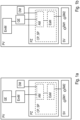
- the position determination device PV has a GNSS receiver GE. This is in particular a GPS receiver.
- the GNSS receiver GE has a receiving antenna and is designed to receive satellite signals from GNSS navigation satellites, to determine a current position of the position determination device PV from the satellite signals.
- the position determination device PV has a determination means EmM, which in the present variant is connected downstream of the GNSS receiver GE.
- the determination means is designed to determine received signal strengths of GNSS signals which are received by the GNSS receiver GE.
- the determination means EmM can also be part of the GNSS receiver GE, but is shown here and in the figure below as an independent module for better illustration.
- the position determination device PV has a processor PZ with a memory SP in which a computer program product CP is stored.
- the Computer program product CP is in the memory SP and is temporarily executed in and by the processor PZ. Therefore, both the computer program product CP and the memory SP are shown as a block in the processor PZ with broken lines.
- the following are stored in the memory SP or run on the processor PZ as part of the computer program product CP: an evaluation means AM and a decision means EsM.
- the processor PZ is designed to receive the received signal strengths determined by the determination means EmM and also the positions determined by the GNSS receiver GE—either indirectly via the determination means EmM or directly from the GNSS receiver GE (pointed communication link).
- the evaluation means AM and the decision means EsM are designed to evaluate the received signal strengths determined and to decide on the basis of a result of the evaluation whether signaling is to be triggered or not. The signaling occurs when it has been established or determined on the basis of the evaluation that there is an imminent lack of operability of the position determination device PV.
- the position determination device PV also has a DSRC module DM, which is coupled to the processor PZ and is designed to receive a trigger signal from a roadside DRSC device and to forward this (possibly in a modified form) to the processor PZ.
- the evaluation means AM is designed to request one or more received signal strengths from the determination module EmM in response to the receipt of the trigger signal.
- the evaluation means AM can alternatively or cumulatively be designed to request one or more received signal strengths from the determination module EmM at predetermined time intervals, randomly or due to other events (e.g. driving in a specific area or crossing a specific border).
- the position determining device PV does not need to include a DSRC module DM.
- Fig. 1b shows a first alternative position determination device PV, in which the determination means EmM is connected upstream of the GNSS receiver GE in the reception path.
- the received signal strengths determined can either be made available to the processor PZ either indirectly via the GNSS receiver GE or directly (point communication link).
- FIG. 1c shows a second alternative position determination device PV, in which the determination means EmM and the GNSS receiver GE each have their own receiving antenna and provide their data to the processor PZ independently of one another.
- the processor PZ can request data on the received signal strength from the determination module EmM and data on the position from the GNSS receiver GE at the same time or within a predetermined time frame of, for example, 0.5 s.
- the position determination device PV is shown schematically together with a central device ZE without receiving and transmitting antennas. While the in 2 The position determination device PV shown also has the GNSS receiver GE and the determination means EmM in order to receive the GNSS signals and determine their received signal strengths, as well as a processor for controlling the components of the position determination device PV, the evaluation means AM and the decision means EsM are in the form of a Computer program product CP stored in the memory SP of the central facility ZE and run or act there.
- the received signal strengths determined are transmitted by the position determination device PV using a radio dFM to the mobile radio network MFN and using a further communication medium zFM (which can be a radio medium, a router or a gateway) to the central facility ZE, at least indirectly (e.g. via the Internet). or the wired telephone network) received from the mobile network MFN.
- a radio dFM to the mobile radio network MFN
- a further communication medium zFM which can be a radio medium, a router or a gateway
- the communication means zFM, dFM are also used to transmit the result of the evaluation of the received signal strengths in the Central device ZE back to the position determination device PV.
- this also has a signaling device SV with signaling means SM1, SM2. While the first signaling device SM1 is an optical signaling device such as an LED, the second signaling device SM2 can be an acoustic signaling device. If the result of the evaluation of the received signal strengths is that a signaling has to be triggered, then this is communicated by the radio means FM from the central facility ZE to the position determination device PV and then signaled to the user of the position determination device PV by means of the signal means SM1, SM2.
- the user of the position determination device PV is in particular a vehicle driver or vehicle owner of a vehicle in which the position determination device PV is installed as an on-board unit (OBU) or vehicle device (FzG) or as part of such a device.
- the position determination device PV is also part of a fee collection system. It is designed to receive the satellite signals received by means of the GNSS receiver and to continuously calculate the position of the vehicle. Based on the calculated positions, it can be determined which toll roads, road sections, traffic structures, etc. the vehicle has traveled on, in order to be able to bill the vehicle owner for this.
- the signaling device SV is used to signal to the vehicle driver or vehicle owner that the position determination device PV is imminent to be inoperable, in particular to fail.
- the position determination device PV according to 1 is thus part of a signaling system according to the invention.
- the 2 Central device ZE shown can at least temporarily as part of the signaling system with a plurality of position determination devices PV1, PV2, PV3 are in communication contact with the mobile radio network, with the position determination devices PV1, PV2, PV3 each being arranged in a vehicle (not shown in the figures). This will be in the 3 illustrated.
- the method according to the invention for signaling the impending lack of operability of the position determination device PV according to a preferred embodiment is 4 explained below using a flowchart.
- the method described here can be carried out by means of the position determination devices PV in the integrated embodiment 1 or by means of the signaling system designed as a distributed system with the position determination device PV and the central device ZE according to FIG 2 be performed.
- a signal strength of a satellite signal received by the GNSS receiver is first determined at a point in time t1. This can be, for example, the reception signal strength of the satellite signal with the strongest signal arriving at the GNSS receiver or at its antenna.
- the received signal strength determined at time t1 serves as the first data point or measurement point in a sequence of measurement points. These measurement points are determined by continuously determining further received signal strengths at a specific point in time and including them in the sequence, with each time a further received signal strength is determined, this received signal strength is compared with the previous received signal strength.
- a signal strength of the satellite signal received by the GNSS receiver is determined at a point in time later than t1.
- this can be the received signal strength of the satellite signal with the strongest signal at this later point in time, arriving at the GNSS receiver or at its antenna.
- the difference between the last two received signal strengths determined calculated. If this difference is less than a predetermined deviation threshold value, then nothing further is done and a subsequent received signal strength can be determined at the next available opportunity.
- the chronologically preceding received signal strength is then fed back as the first received signal strength and the following received signal strength as the second received signal strength for difference formation and comparison with the threshold value.
- the difference can be the absolute difference in the form of a relative distance between the two received signal strengths, which is compared with the deviation threshold value (always positive in this case).
- the position determination device PV is impaired and is about to lose its operability.
- the position determination device PV is or was at a location with limited reception when determining the first received signal strength or the second received signal strength, for example in a tunnel or in a narrow valley where the satellite signals do not penetrate well .
- a position of the position determination device is determined.
- This map information-related geodata describes areas in which weak or no GNSS signal reception must be expected due to topographical features in the course of the road (tunnel, ravine) that can be derived from a digital map.
- a corresponding set of such weak reception areas can be stored in a memory inside or outside the position determination device, in particular in the central facility.
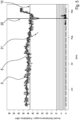
- the Figures 5 to 7 show in a diagram an example of the result of a sequence of received signal strengths determined a few months before and up to a lack of operability for three different position determination devices PV.
- the received signal strengths were recorded continuously.
- the last received signal strength recorded or an average value from a number of several received signal strengths recorded last can be regarded as the second determined received signal strength.
- any received signal strength detected prior to the most recently detected received signal strength or an average of a plurality of received signal strengths detected prior to the plurality of most recently detected received signal strengths may be regarded as the determined first received signal strength.
- the time course is plotted along the abscissa, with the order broken down into days.
- the position determination device PV was not used, and in particular the vehicle was not operated. Based on figure 5 it can be seen that the vehicle was used regularly for 6 days in a row and was rested for one day in between. On each day, a determination of a received signal strength took place at least once, but usually between two and five times. This process was triggered by driving past a control point or control bridge at which a short-distance radio device, in particular a DSRC transmission device, was arranged.
- the determination of the received signal strength was triggered by a radio signal from the control point to the position determination device PV, while the measurement result was radioed back from the position determination device PV to the control point.
- Each measurement result corresponds to an open circle in the diagrams, which indicates a received signal strength along the ordinate in the upper section between the field strength values 10 dBm and 60 dBm. This is the field strength of the satellite signal received by the GNSS receiver GE at the receiving antenna.
- a thin line 6 connects the maximum values 6 of one day of the received signal strengths, while a thicker line 8 traces the course of the average values 8 of the received signal strengths of each day.
- a line 10 parallel to the abscissa indicates a suspicion threshold value 10 .
- This suspicion threshold value 10 can be determined separately for each position determination device PV or each type of position determination device PV.
- the received signal strengths determined by means of these position determination devices PV are usually above this value if the components are faultless.
- the suspicion threshold value 10 was determined in a threshold value determination phase of the duration of a predetermined time frame in the time before the year 2010 by the repeated determination of first received signal strengths in such a way that the position determination device PV at a predetermined distance (in the cases of this exemplary embodiment from 10 dBm) below the mean value of the determined first received signal strengths.
- the position determination device PV can be designed to only determine a suspicion threshold value if no or no more than a predetermined number of first received signal strengths determined in the threshold value determination phase are more than the predetermined distance below the mean value.
- signaling will take place.
- the signaling can take place when no received signal strength determined has yet fallen below the suspected threshold value 10, but a comparison of two or more of the received signal strengths determined indicates an imminent lack of operability of the position determination device PV.
- a signal is only given when both the suspected threshold value 10 has been undershot and a comparison of two or more of the received signal strengths determined indicates an imminent lack of operability of the position determination device PV. Examples of situations in which a comparison of received signal strength indicates an impending lack of Operability of the position determination device PV indicates are explained below.
- the point in time at which the position determination device PV was classified as a defect according to previous warning methods not according to the invention is identified by a line 20 parallel to the ordinate and is referred to below as the defect point in time 20 .
- the defect point in time 20 is therefore a point in time at which, according to the manufacturer's specifications, the position determination device PV would have to be serviced.
- conventional position-determining devices have acoustic and optical warning or error displays that inform the user of a defect.
- the decision that a defect point in time 20 has been reached can be based on the evaluation of the number of non-detections within a certain period of time and/or the number of consecutive non-detections. How to get into the Figures 5 to 7 can see, the number of non-detections accumulates in the vicinity of the defect time 20.
- an outlier value 31 of a received signal strength is visible.
- the distances between the outlier value 31 and a preceding and a following received signal strength are approximately 10 dBm.
- the outlier value 31 is already determined more than two weeks before the defect time 20, so that a signaling could have taken place even then. Will he If the outlier value 31 is treated as the second received signal strength in the continuous determination of received signal strengths, then it has a distance of 10 dBm from a previously determined first received signal strength. If the evaluation of the two received signal strengths includes a difference formation and a comparison with a deviation threshold value, and if the deviation threshold value is set to 5 dBm or 8 dBm, then the evaluation result will lead to a signaling.
- Another outlier value 32 is in the chart in FIG 7 recognizable, which occurs in the second half of June.
- This outlier value 32 is significantly more than 10 dBm apart from another received signal strength determined on the same day.
- a received signal strength determined successively by difference formation with a predetermined deviation threshold value of 5 dBm or 8 dBm would lead to a signaling.
- the outlier value 32 was determined about 2 months before the defect time 20. This means that the signaling based on the method according to the invention would take place about 2 months before the actual failure of the position determination device PV.
- the situation would be over 7 the signaling can also take place at the time when the outlier value 32 occurs, i.e. in the second half of June.
- the signaling when the suspected threshold value 10 is undershot for the first time does not only take place at the beginning of August, but already at the end of June.
- the received signal strength values of the position determination device PV in 6 do not have single outlier values 31, 32 as in the other two cases. However, at least two jumps 34, 35 can be clearly seen, which occurred a few weeks before the point in time 20 of the defect.
- a first jump 34 the mean value calculated over a day falls Received signal strengths from one day on which the received signal strength was determined to the next by about 5 to 6 dBm.
- a second jump 35 a difference between a first received signal strength and a second received signal strength is also more than 5 dBm.
- Each of the two jumps 34, 35 can in itself trigger a signaling.
- Signaling preferably takes place when the evaluation shows that the difference between a second received signal strength or an average value from a plurality of second received signal strengths and a first received signal strength exceeds a deviation threshold value of 5 dBm.
- the signaling can only be carried out when the second jump 35 has also been registered after the first jump 34 .
- Such a signaling generally takes place when the evaluation shows that said difference exceeds the deviation threshold value several times.
- the vertical dashed line 40 drawn in indicates a repair time 40 at which the position determination device PV was repaired or readjusted or calibrated. The received signal strengths determined after this point in time are again well above the suspicion threshold value 10 of 38 dBm.
- the decision as to whether signaling takes place and, if so, when the signaling takes place depends on the rule that is used in the evaluation and decision.
- the point in time at which signaling takes place can be determined from the Figures 5 to 7
- the easiest way to read off the rule is that the first received signal strength falls below the selected or calculated suspicion threshold value 10 of 38 dBm. In this case, all three situations (according to figure 5 , 6 and 7 ) the signaling will be done in the second half of June) - in the situation after 7 a few days earlier than in the situations after figure 5 or 6 .
Landscapes
- Engineering & Computer Science (AREA)
- Radar, Positioning & Navigation (AREA)
- Remote Sensing (AREA)
- Computer Networks & Wireless Communication (AREA)
- Physics & Mathematics (AREA)
- General Physics & Mathematics (AREA)
- Business, Economics & Management (AREA)
- Finance (AREA)
- Position Fixing By Use Of Radio Waves (AREA)
Claims (10)
- Un procédé de signalisation d'un défaut imminent d'opérabilité d'un dispositif de détermination de position (PV) équipé d'un récepteur GNSS (GE), le procédé comprenant les étapes suivantes :- déterminer une première intensité du signal de réception d'un signal GNSS reçu par le récepteur GNSS (GE),- déterminer au moins une seconde intensité du signal de réception du signal GNSS reçu par le récepteur GNSS (GE),- évaluer la première intensité du signal de réception et au moins la seconde intensité du signal de réception et générer un résultat de l'évaluation,- déterminer la position du dispositif de détermination de position (PV) au moyen du signal GNSS reçu du récepteur GNSS (GE),- comparer la position déterminée avec un ensemble de zones de faible réception stockées dans une mémoire où des interférences et/ou une absence de réception GNSS sont connues, et- décider du déclenchement d'une signalisation en fonction du résultat de l'évaluation et de la comparaison de position,dans lequel la première intensité du signal de réception du signal GNSS reçu par le récepteur GNSS (GE) est déterminée à un premier temps de réception ou moyennée sur une pluralité de premiers temps de réception ou sur une première plage de temps de réception, et dans lequel la seconde intensité du signal de réception du signal GNSS reçu par le récepteur GNSS (GE) est déterminée à un second temps de réception ou moyennée sur une pluralité de seconds temps de réception ou sur une seconde plage de temps de réception,dans lequel l'évaluation de la première intensité du signal de réception et de la seconde intensité du signal de réception comprend une comparaison de la première intensité du signal de réception avec la seconde intensité du signal de réception, dans lequel le déclenchement de la signalisation a lieu lorsque la seconde intensité du signal de réception dévie de la première intensité du signal de réception par une valeur de seuil de déviation prédéterminée et la position déterminée n'est pas corrélée à une zone de faible réception.
- Le procédé selon la revendication 1, dans lequel la première intensité déterminée du signal de réception et la seconde intensité déterminée du signal de réception appartiennent à une séquence des intensités du signal de réception du signal GNSS reçu par le récepteur GNSS (GE), qui sont déterminées en continu.
- Le procédé selon l'une quelconque des revendications précédentes, dans lequel en fonction du résultat de l'évaluation, il est décidé également qu'une signalisation est déclenchée si le dispositif de détermination de position (PV) peut effectuer au moyen du signal GNSS reçu du récepteur GNSS (GE) une détermination de position auprès la première intensité du signal de réception et à la seconde intensité du signal de réception respectivement.
- Un système de signalisation pour signalisation d'un défaut imminent d'opérabilité d'un dispositif de détermination de position (PV) équipé d'un récepteur GNSS (GE), comprenant:- le dispositif de détermination de position (PV) avec le récepteur GNSS (GE),- un moyen de détermination (EmM), qui est conçu pour déterminer une première intensité de signal de réception d'un signal GNSS reçu du récepteur GNSS (GE) à un premier temps de réception ou moyennée sur une pluralité de premiers temps de réception ou sur une première plage de temps de réception et au moins une seconde intensité de signal de réception du signal GNSS reçu du récepteur GNSS (GE) à un second temps de réception ou moyennée sur une pluralité de seconds temps de réception ou sur une seconde plage de temps de réception,- un moyen d'évaluation (AM), qui est conçu pour évaluer la première intensité du signal de réception et au moins la seconde intensité du signal de réception et pour générer un résultat d'évaluation, dans lequel l'évaluation comprend une comparaison de la première intensité du signal de réception avec la seconde intensité du signal de réception,- un moyen qui est conçu pour déterminer la position du dispositif de détermination de position (PV) au moyen du signal GNSS reçu du récepteur GNSS (GE),- un moyen qui est conçu pour comparer la position déterminée avec un ensemble de zones de faible réception déposées dans une mémoire où une interférence et/ou une absence de réception GNSS sont connues, et- un moyen de décision (EsM), qui est conçu pour décider en fonction du résultat de l'évaluation et du résultat de la comparaison de position sur le déclenchement d'une signalisation de sorte que le déclenchement de la signalisation ait lieu lorsque la seconde intensité du signal de réception dévie de la première intensité du signal de réception par une valeur de seuil prédéterminée et la position déterminée n'est pas corrélée avec une zone de faible réception.
- Un système de signalisation selon la revendication 4, dans lequel les moyens d'évaluation (AM) et/ou les moyens de décision (EsM) sont/est disposés dans le dispositif de détermination de position (PV).
- Le système de signalisation selon la revendication 4, dans lequel le dispositif de détermination de position (PV) comprend les moyens de détermination (EmM) et un dispositif radio (dFV), qui est conçu pour transmettre la première intensité du signal de réception et/ou la seconde intensité du signal de réception par radio à un dispositif central (ZE), dans lequel le dispositif central (ZE) a les moyens d'évaluation (AM) et les moyens de décision (EsM).
- Le système de signalisation selon l'une quelconque des revendications 4 à 6, dans lequel le dispositif de détermination de position (PV) a un dispositif de signalisation (SV) et est conçu, en cas de décision positive des moyens de décision (EsM) sur le déclenchement de la signalisation, pour déclencher la signalisation.
- Un système de tarification avec un système de signalisation selon l'une quelconque des revendications 4 à 7 et un dispositif de calcul de redevances qui est conçu pour calculer une redevance à payer pour la conduite sur les voies de circulation en fonction des positions déterminées au moyen du dispositif de détermination de position (PV) sur la base des signaux reçus par le récepteur GNSS (GE) et pour facturer à un propriétaire du véhicule associé au dispositif de détermination de position (PV).
- Un dispositif de détermination de position (PV) avec un récepteur GNSS (GE), un moyen de détection (EmM), qui est conçu pour déterminer une première intensité d'un signal de réception d'un signal GNSS reçu par le récepteur GNSS (GE) à un premier temps de réception ou moyenner sur une pluralité de premiers temps de réception ou sur une première plage de temps de réception et déterminer au moins une seconde intensité du signal de réception du signal GNSS reçu par le récepteur GNSS (GE) à un second temps de réception ou moyenner sur une pluralité de seconds temps de réception ou sur une seconde plage de temps de réception, un moyen d'évaluation (AM), qui est conçu pour évaluer la première intensité du signal de réception et la seconde intensité du signal de réception et pour générer un résultat d'évaluation, dans lequel l'évaluation comprend une comparaison de la première intensité du signal de réception avec la seconde intensité du signal de réception, un moyen, qui est conçu pour déterminer une position du dispositif de détermination de position (PV) au moyen du signal GNSS reçu par le récepteur GNSS (GE), un moyen, qui est conçu pour comparer la position déterminée avec un ensemble de zones de faible réception déposées dans une mémoire où des interférences et / ou une absence de réception GNSS sont connues, et un moyen de décision (EsM), qui est conçu pour déclencher une signalisation en fonction du résultat de l'évaluation et du résultat de la comparaison de position, lorsque la seconde intensité du signal dévie de la première intensité du signal par une valeur de seuil de déviation prédéterminée et la position déterminée n'est pas corrélée à une zone de faible réception.
- Un produit de programme d'ordinateur (CP) pour signaler un défaut imminent d'opérabilité d'un dispositif de détermination de position (PV) équipé d'un récepteur GNSS (GE), qui contient des commandes qui provoquent lors de l'exécution du programme par un ordinateur celui-ci à performer au moins les étapes suivantes :- évaluer une première intensité du signal de réception d'un signal GNSS reçu par le récepteur GNSS (GE) déterminée à un premier temps de réception ou moyennée sur une pluralité de premiers temps de réception ou sur une première plage de temps de réception et une seconde intensité du signal de réception d'un signal GNSS reçu par le récepteur GNSS (GE) déterminée à un second temps de réception ou moyennée sur une pluralité de seconds temps de réception ou sur une seconde plage de temps de réception;- comparer une position du dispositif de détermination de position (PV) déterminée au moyen du signal GNSS reçu par le récepteur GNSS (GE) avec un ensemble de zones de faible réception stockées dans une mémoire où des interférences et/ou une absence de réception GNSS sont connues, et- décider que la signalisation est déclenchée, en fonction du résultat de l'évaluation et de la comparaison de position, dans lequel l'évaluation de la première intensité du signal de réception et de la seconde intensité du signal de réception comprend une comparaison de la première intensité du signal de réception avec la seconde intensité du signal de réception, dans lequel le déclenchement de la signalisation est effectué si la seconde intensité du signal de réception dévie de la première intensité du signal de réception par une valeur de seuil de déviation prédéterminée et la position déterminée n'est pas corrélée avec une zone de faible réception.
Priority Applications (1)
| Application Number | Priority Date | Filing Date | Title |
|---|---|---|---|
| EP16206148.5A EP3339906B1 (fr) | 2016-12-22 | 2016-12-22 | Procédé, système, dispositif et produit-programme informatique de signalisation d'une capacité de fonctionnement défaillante imminente d'un dispositif de détermination de position, et système de péage |
Applications Claiming Priority (1)
| Application Number | Priority Date | Filing Date | Title |
|---|---|---|---|
| EP16206148.5A EP3339906B1 (fr) | 2016-12-22 | 2016-12-22 | Procédé, système, dispositif et produit-programme informatique de signalisation d'une capacité de fonctionnement défaillante imminente d'un dispositif de détermination de position, et système de péage |
Publications (2)
| Publication Number | Publication Date |
|---|---|
| EP3339906A1 EP3339906A1 (fr) | 2018-06-27 |
| EP3339906B1 true EP3339906B1 (fr) | 2023-03-29 |
Family
ID=57588899
Family Applications (1)
| Application Number | Title | Priority Date | Filing Date |
|---|---|---|---|
| EP16206148.5A Active EP3339906B1 (fr) | 2016-12-22 | 2016-12-22 | Procédé, système, dispositif et produit-programme informatique de signalisation d'une capacité de fonctionnement défaillante imminente d'un dispositif de détermination de position, et système de péage |
Country Status (1)
| Country | Link |
|---|---|
| EP (1) | EP3339906B1 (fr) |
Family Cites Families (9)
| Publication number | Priority date | Publication date | Assignee | Title |
|---|---|---|---|---|
| JP3775033B2 (ja) * | 1997-12-17 | 2006-05-17 | マツダ株式会社 | 移動体用ディファレンシャルgps装置 |
| JP2000310673A (ja) * | 1999-04-26 | 2000-11-07 | Matsushita Electric Ind Co Ltd | Gps受信機 |
| JP4258225B2 (ja) * | 2003-02-14 | 2009-04-30 | トヨタ自動車株式会社 | 車両の位置検出装置及び方法 |
| DK2487506T3 (da) | 2011-02-10 | 2014-08-18 | Toll Collect Gmbh | Positionsbestemmelsesapparat samt fremgangsmåde og computerprogram-produkt til signalering af et positionsbestemmelsesapparats manglende driftsevne |
| AT512743A1 (de) * | 2012-04-11 | 2013-10-15 | Fts Computertechnik Gmbh | Verfahren und Masterclock zur Erstellung von fail-silent Synchronisationsnachrichten |
| CN103116168B (zh) * | 2013-02-01 | 2015-02-04 | 珠海德百祺科技有限公司 | 一种导航定位装置的异常检测及处理方法和装置 |
| CN103777215B (zh) * | 2014-02-12 | 2018-05-22 | 厦门雅迅网络股份有限公司 | 一种恶意屏蔽gps天线的检测方法 |
| PL2924662T3 (pl) * | 2014-03-27 | 2017-01-31 | Kapsch Trafficcom Ag | Jednostka pokładowa i sposób nadzorowania działania w systemie poboru opłat drogowych |
| EP3002734B1 (fr) * | 2014-10-02 | 2021-12-01 | Toll Collect GmbH | Dispositifs de véhicule et système de péage |
-
2016
- 2016-12-22 EP EP16206148.5A patent/EP3339906B1/fr active Active
Also Published As
| Publication number | Publication date |
|---|---|
| EP3339906A1 (fr) | 2018-06-27 |
Similar Documents
| Publication | Publication Date | Title |
|---|---|---|
| DE102009034214B4 (de) | System für die Kenntnis und Diagnose von Kommunikationsmerkmalen zwischen Fahrzeugen | |
| EP2535731B1 (fr) | Dispositif de localisation et de suivi d'un véhicule | |
| EP2924662B1 (fr) | Unité embarquée et procédé de surveillance du fonctionnement dans un système de péage routier | |
| DE3613226A1 (de) | Funkmess-, navigations- und ortungssystem mit korrektur systematischer fehler | |
| DE102006045404A1 (de) | Telematikverfahren und -system | |
| EP2128639B1 (fr) | Procédé d'amélioration de la continuité dans un système de navigation satellite à double fréquence | |
| DE102020213315A1 (de) | Verfahren zur GNSS-basierten Lokalisierung eines Fahrzeugs mit einer GNSS-Lokalisierungseinrichtung, unter Berücksichtigung von Integritätsinformationen, die zu GNSS-Korrekturdaten bereitgestellt werden | |
| EP2078965B1 (fr) | Dispositif de surveillance pour un système augmenté de détermination de position par satellite et système augmenté de détermination de position par satellite | |
| DE102013107962B4 (de) | Verfahren zur Überwachung von Komponenten eines Systems, kooperatives Fahrzeugfahrerassistenzsystem, Infrastruktureinrichtung sowie Computerprogramm | |
| EP1430328B1 (fr) | Procede et dispositif de determination de l'emplacement d'une station de base | |
| EP3687879B1 (fr) | Localisation de véhicule ferroviaire | |
| EP3279870A1 (fr) | Dispositif de traitement de donnees, systeme et procede de controle de realisation de la fonction conforme d'un dispositif de determination de position | |
| EP3339906B1 (fr) | Procédé, système, dispositif et produit-programme informatique de signalisation d'une capacité de fonctionnement défaillante imminente d'un dispositif de détermination de position, et système de péage | |
| EP3339903B1 (fr) | Procédé, système, dispositif et produit-programme informatique de signalisation d'un dysfonctionnement ou d'un dysfonctionnement imminent d'un dispositif de détermination de position, et système de péage | |
| DE102018220793A1 (de) | Erkennung von fehlerhaften Positionsbestimmungen | |
| EP3495847B1 (fr) | Agencement de tachygraphe et procédé de fonctionnement d'un agencement de tachygraphe | |
| WO2018210487A1 (fr) | Procédé, dispositif et système permettant de déterminer une zone météorologique | |
| EP3279692B1 (fr) | Dispositif de traitement de donnees, systeme et procede de controle de realisation de la fonction conforme d'un dispositif de determination de position | |
| EP3339905A1 (fr) | Procédé, système, dispositif et produit-programme informatique de signalisation d'un dysfonctionnement ou d'un dysfonctionnement imminent d'un dispositif de détermination de position, et système de péage | |
| EP3339907B1 (fr) | Procédé de signalisation d'un dysfonctionnement d'un dispositif de détermination de position, système de signalisation, système de péage, dispositif de détermination de position et produit-programme informatique | |
| EP3800811B1 (fr) | Détection d'un signal de brouillage radio et / ou d'un émetteur de brouillage | |
| DE102017204535A1 (de) | Verfahren und System zum Ergänzen einer auf einem Zentralrechner gespeicherten digitalen Karte eines Verkehrswegenetzes | |
| DE102008011824A1 (de) | Verwendung von Phasor Measurement Units für differentielle Globale Satellitennavigationssysteme (GNSS) | |
| EP3188389B1 (fr) | Dispositif, systeme et procede d'enregistrement d'un signal parasite | |
| EP4079007A1 (fr) | Test de fiabilité automatisé d'un système de capteur de surveillance monté sur une infrastructure |
Legal Events
| Date | Code | Title | Description |
|---|---|---|---|
| PUAI | Public reference made under article 153(3) epc to a published international application that has entered the european phase |
Free format text: ORIGINAL CODE: 0009012 |
|
| STAA | Information on the status of an ep patent application or granted ep patent |
Free format text: STATUS: THE APPLICATION HAS BEEN PUBLISHED |
|
| AK | Designated contracting states |
Kind code of ref document: A1 Designated state(s): AL AT BE BG CH CY CZ DE DK EE ES FI FR GB GR HR HU IE IS IT LI LT LU LV MC MK MT NL NO PL PT RO RS SE SI SK SM TR |
|
| AX | Request for extension of the european patent |
Extension state: BA ME |
|
| STAA | Information on the status of an ep patent application or granted ep patent |
Free format text: STATUS: REQUEST FOR EXAMINATION WAS MADE |
|
| 17P | Request for examination filed |
Effective date: 20181220 |
|
| RBV | Designated contracting states (corrected) |
Designated state(s): AL AT BE BG CH CY CZ DE DK EE ES FI FR GB GR HR HU IE IS IT LI LT LU LV MC MK MT NL NO PL PT RO RS SE SI SK SM TR |
|
| STAA | Information on the status of an ep patent application or granted ep patent |
Free format text: STATUS: EXAMINATION IS IN PROGRESS |
|
| 17Q | First examination report despatched |
Effective date: 20200921 |
|
| GRAP | Despatch of communication of intention to grant a patent |
Free format text: ORIGINAL CODE: EPIDOSNIGR1 |
|
| STAA | Information on the status of an ep patent application or granted ep patent |
Free format text: STATUS: GRANT OF PATENT IS INTENDED |
|
| INTG | Intention to grant announced |
Effective date: 20221018 |
|
| GRAS | Grant fee paid |
Free format text: ORIGINAL CODE: EPIDOSNIGR3 |
|
| GRAA | (expected) grant |
Free format text: ORIGINAL CODE: 0009210 |
|
| STAA | Information on the status of an ep patent application or granted ep patent |
Free format text: STATUS: THE PATENT HAS BEEN GRANTED |
|
| AK | Designated contracting states |
Kind code of ref document: B1 Designated state(s): AL AT BE BG CH CY CZ DE DK EE ES FI FR GB GR HR HU IE IS IT LI LT LU LV MC MK MT NL NO PL PT RO RS SE SI SK SM TR |
|
| REG | Reference to a national code |
Ref country code: GB Ref legal event code: FG4D Free format text: NOT ENGLISH |
|
| REG | Reference to a national code |
Ref country code: CH Ref legal event code: EP |
|
| REG | Reference to a national code |
Ref country code: DE Ref legal event code: R096 Ref document number: 502016015656 Country of ref document: DE |
|
| REG | Reference to a national code |
Ref country code: AT Ref legal event code: REF Ref document number: 1557084 Country of ref document: AT Kind code of ref document: T Effective date: 20230415 |
|
| REG | Reference to a national code |
Ref country code: IE Ref legal event code: FG4D Free format text: LANGUAGE OF EP DOCUMENT: GERMAN |
|
| REG | Reference to a national code |
Ref country code: LT Ref legal event code: MG9D |
|
| PG25 | Lapsed in a contracting state [announced via postgrant information from national office to epo] |
Ref country code: RS Free format text: LAPSE BECAUSE OF FAILURE TO SUBMIT A TRANSLATION OF THE DESCRIPTION OR TO PAY THE FEE WITHIN THE PRESCRIBED TIME-LIMIT Effective date: 20230329 Ref country code: NO Free format text: LAPSE BECAUSE OF FAILURE TO SUBMIT A TRANSLATION OF THE DESCRIPTION OR TO PAY THE FEE WITHIN THE PRESCRIBED TIME-LIMIT Effective date: 20230629 Ref country code: LV Free format text: LAPSE BECAUSE OF FAILURE TO SUBMIT A TRANSLATION OF THE DESCRIPTION OR TO PAY THE FEE WITHIN THE PRESCRIBED TIME-LIMIT Effective date: 20230329 Ref country code: LT Free format text: LAPSE BECAUSE OF FAILURE TO SUBMIT A TRANSLATION OF THE DESCRIPTION OR TO PAY THE FEE WITHIN THE PRESCRIBED TIME-LIMIT Effective date: 20230329 Ref country code: HR Free format text: LAPSE BECAUSE OF FAILURE TO SUBMIT A TRANSLATION OF THE DESCRIPTION OR TO PAY THE FEE WITHIN THE PRESCRIBED TIME-LIMIT Effective date: 20230329 |
|
| REG | Reference to a national code |
Ref country code: NL Ref legal event code: MP Effective date: 20230329 |
|
| PG25 | Lapsed in a contracting state [announced via postgrant information from national office to epo] |
Ref country code: SE Free format text: LAPSE BECAUSE OF FAILURE TO SUBMIT A TRANSLATION OF THE DESCRIPTION OR TO PAY THE FEE WITHIN THE PRESCRIBED TIME-LIMIT Effective date: 20230329 Ref country code: NL Free format text: LAPSE BECAUSE OF FAILURE TO SUBMIT A TRANSLATION OF THE DESCRIPTION OR TO PAY THE FEE WITHIN THE PRESCRIBED TIME-LIMIT Effective date: 20230329 Ref country code: GR Free format text: LAPSE BECAUSE OF FAILURE TO SUBMIT A TRANSLATION OF THE DESCRIPTION OR TO PAY THE FEE WITHIN THE PRESCRIBED TIME-LIMIT Effective date: 20230630 Ref country code: FI Free format text: LAPSE BECAUSE OF FAILURE TO SUBMIT A TRANSLATION OF THE DESCRIPTION OR TO PAY THE FEE WITHIN THE PRESCRIBED TIME-LIMIT Effective date: 20230329 |
|
| PG25 | Lapsed in a contracting state [announced via postgrant information from national office to epo] |
Ref country code: SM Free format text: LAPSE BECAUSE OF FAILURE TO SUBMIT A TRANSLATION OF THE DESCRIPTION OR TO PAY THE FEE WITHIN THE PRESCRIBED TIME-LIMIT Effective date: 20230329 Ref country code: RO Free format text: LAPSE BECAUSE OF FAILURE TO SUBMIT A TRANSLATION OF THE DESCRIPTION OR TO PAY THE FEE WITHIN THE PRESCRIBED TIME-LIMIT Effective date: 20230329 Ref country code: PT Free format text: LAPSE BECAUSE OF FAILURE TO SUBMIT A TRANSLATION OF THE DESCRIPTION OR TO PAY THE FEE WITHIN THE PRESCRIBED TIME-LIMIT Effective date: 20230731 Ref country code: ES Free format text: LAPSE BECAUSE OF FAILURE TO SUBMIT A TRANSLATION OF THE DESCRIPTION OR TO PAY THE FEE WITHIN THE PRESCRIBED TIME-LIMIT Effective date: 20230329 Ref country code: EE Free format text: LAPSE BECAUSE OF FAILURE TO SUBMIT A TRANSLATION OF THE DESCRIPTION OR TO PAY THE FEE WITHIN THE PRESCRIBED TIME-LIMIT Effective date: 20230329 |
|
| PG25 | Lapsed in a contracting state [announced via postgrant information from national office to epo] |
Ref country code: SK Free format text: LAPSE BECAUSE OF FAILURE TO SUBMIT A TRANSLATION OF THE DESCRIPTION OR TO PAY THE FEE WITHIN THE PRESCRIBED TIME-LIMIT Effective date: 20230329 Ref country code: PL Free format text: LAPSE BECAUSE OF FAILURE TO SUBMIT A TRANSLATION OF THE DESCRIPTION OR TO PAY THE FEE WITHIN THE PRESCRIBED TIME-LIMIT Effective date: 20230329 Ref country code: IS Free format text: LAPSE BECAUSE OF FAILURE TO SUBMIT A TRANSLATION OF THE DESCRIPTION OR TO PAY THE FEE WITHIN THE PRESCRIBED TIME-LIMIT Effective date: 20230729 |
|
| REG | Reference to a national code |
Ref country code: DE Ref legal event code: R097 Ref document number: 502016015656 Country of ref document: DE |
|
| P01 | Opt-out of the competence of the unified patent court (upc) registered |
Effective date: 20231207 |
|
| PG25 | Lapsed in a contracting state [announced via postgrant information from national office to epo] |
Ref country code: DK Free format text: LAPSE BECAUSE OF FAILURE TO SUBMIT A TRANSLATION OF THE DESCRIPTION OR TO PAY THE FEE WITHIN THE PRESCRIBED TIME-LIMIT Effective date: 20230329 Ref country code: CZ Free format text: LAPSE BECAUSE OF FAILURE TO SUBMIT A TRANSLATION OF THE DESCRIPTION OR TO PAY THE FEE WITHIN THE PRESCRIBED TIME-LIMIT Effective date: 20230329 |
|
| PLBE | No opposition filed within time limit |
Free format text: ORIGINAL CODE: 0009261 |
|
| STAA | Information on the status of an ep patent application or granted ep patent |
Free format text: STATUS: NO OPPOSITION FILED WITHIN TIME LIMIT |
|
| 26N | No opposition filed |
Effective date: 20240103 |
|
| PG25 | Lapsed in a contracting state [announced via postgrant information from national office to epo] |
Ref country code: SI Free format text: LAPSE BECAUSE OF FAILURE TO SUBMIT A TRANSLATION OF THE DESCRIPTION OR TO PAY THE FEE WITHIN THE PRESCRIBED TIME-LIMIT Effective date: 20230329 |
|
| PG25 | Lapsed in a contracting state [announced via postgrant information from national office to epo] |
Ref country code: SI Free format text: LAPSE BECAUSE OF FAILURE TO SUBMIT A TRANSLATION OF THE DESCRIPTION OR TO PAY THE FEE WITHIN THE PRESCRIBED TIME-LIMIT Effective date: 20230329 Ref country code: IT Free format text: LAPSE BECAUSE OF FAILURE TO SUBMIT A TRANSLATION OF THE DESCRIPTION OR TO PAY THE FEE WITHIN THE PRESCRIBED TIME-LIMIT Effective date: 20230329 |
|
| REG | Reference to a national code |
Ref country code: CH Ref legal event code: PL |
|
| PG25 | Lapsed in a contracting state [announced via postgrant information from national office to epo] |
Ref country code: LU Free format text: LAPSE BECAUSE OF NON-PAYMENT OF DUE FEES Effective date: 20231222 |
|
| PG25 | Lapsed in a contracting state [announced via postgrant information from national office to epo] |
Ref country code: MC Free format text: LAPSE BECAUSE OF FAILURE TO SUBMIT A TRANSLATION OF THE DESCRIPTION OR TO PAY THE FEE WITHIN THE PRESCRIBED TIME-LIMIT Effective date: 20230329 |
|
| GBPC | Gb: european patent ceased through non-payment of renewal fee |
Effective date: 20231222 |
|
| REG | Reference to a national code |
Ref country code: BE Ref legal event code: MM Effective date: 20231231 |
|
| PG25 | Lapsed in a contracting state [announced via postgrant information from national office to epo] |
Ref country code: MC Free format text: LAPSE BECAUSE OF FAILURE TO SUBMIT A TRANSLATION OF THE DESCRIPTION OR TO PAY THE FEE WITHIN THE PRESCRIBED TIME-LIMIT Effective date: 20230329 Ref country code: LU Free format text: LAPSE BECAUSE OF NON-PAYMENT OF DUE FEES Effective date: 20231222 |
|
| REG | Reference to a national code |
Ref country code: IE Ref legal event code: MM4A |
|
| PG25 | Lapsed in a contracting state [announced via postgrant information from national office to epo] |
Ref country code: IE Free format text: LAPSE BECAUSE OF NON-PAYMENT OF DUE FEES Effective date: 20231222 |
|
| PG25 | Lapsed in a contracting state [announced via postgrant information from national office to epo] |
Ref country code: GB Free format text: LAPSE BECAUSE OF NON-PAYMENT OF DUE FEES Effective date: 20231222 |
|
| PG25 | Lapsed in a contracting state [announced via postgrant information from national office to epo] |
Ref country code: BE Free format text: LAPSE BECAUSE OF NON-PAYMENT OF DUE FEES Effective date: 20231231 |
|
| PG25 | Lapsed in a contracting state [announced via postgrant information from national office to epo] |
Ref country code: FR Free format text: LAPSE BECAUSE OF NON-PAYMENT OF DUE FEES Effective date: 20231231 |
|
| PG25 | Lapsed in a contracting state [announced via postgrant information from national office to epo] |
Ref country code: CH Free format text: LAPSE BECAUSE OF NON-PAYMENT OF DUE FEES Effective date: 20231231 |
|
| PG25 | Lapsed in a contracting state [announced via postgrant information from national office to epo] |
Ref country code: IE Free format text: LAPSE BECAUSE OF NON-PAYMENT OF DUE FEES Effective date: 20231222 Ref country code: GB Free format text: LAPSE BECAUSE OF NON-PAYMENT OF DUE FEES Effective date: 20231222 Ref country code: FR Free format text: LAPSE BECAUSE OF NON-PAYMENT OF DUE FEES Effective date: 20231231 Ref country code: CH Free format text: LAPSE BECAUSE OF NON-PAYMENT OF DUE FEES Effective date: 20231231 Ref country code: BE Free format text: LAPSE BECAUSE OF NON-PAYMENT OF DUE FEES Effective date: 20231231 |
|
| PG25 | Lapsed in a contracting state [announced via postgrant information from national office to epo] |
Ref country code: BG Free format text: LAPSE BECAUSE OF FAILURE TO SUBMIT A TRANSLATION OF THE DESCRIPTION OR TO PAY THE FEE WITHIN THE PRESCRIBED TIME-LIMIT Effective date: 20230329 |
|
| PG25 | Lapsed in a contracting state [announced via postgrant information from national office to epo] |
Ref country code: BG Free format text: LAPSE BECAUSE OF FAILURE TO SUBMIT A TRANSLATION OF THE DESCRIPTION OR TO PAY THE FEE WITHIN THE PRESCRIBED TIME-LIMIT Effective date: 20230329 |
|
| REG | Reference to a national code |
Ref country code: AT Ref legal event code: MM01 Ref document number: 1557084 Country of ref document: AT Kind code of ref document: T Effective date: 20231222 |
|
| PG25 | Lapsed in a contracting state [announced via postgrant information from national office to epo] |
Ref country code: AT Free format text: LAPSE BECAUSE OF NON-PAYMENT OF DUE FEES Effective date: 20231222 |
|
| PG25 | Lapsed in a contracting state [announced via postgrant information from national office to epo] |
Ref country code: CY Free format text: LAPSE BECAUSE OF FAILURE TO SUBMIT A TRANSLATION OF THE DESCRIPTION OR TO PAY THE FEE WITHIN THE PRESCRIBED TIME-LIMIT; INVALID AB INITIO Effective date: 20161222 |
|
| PG25 | Lapsed in a contracting state [announced via postgrant information from national office to epo] |
Ref country code: HU Free format text: LAPSE BECAUSE OF FAILURE TO SUBMIT A TRANSLATION OF THE DESCRIPTION OR TO PAY THE FEE WITHIN THE PRESCRIBED TIME-LIMIT; INVALID AB INITIO Effective date: 20161222 |
|
| PG25 | Lapsed in a contracting state [announced via postgrant information from national office to epo] |
Ref country code: TR Free format text: LAPSE BECAUSE OF FAILURE TO SUBMIT A TRANSLATION OF THE DESCRIPTION OR TO PAY THE FEE WITHIN THE PRESCRIBED TIME-LIMIT Effective date: 20230329 |
|
| PGFP | Annual fee paid to national office [announced via postgrant information from national office to epo] |
Ref country code: DE Payment date: 20251222 Year of fee payment: 10 |